EP1625918A2 - Programmiervorrichtung zum Zurückfahren eines Roboters in seiner Wartestellung - Google Patents
Programmiervorrichtung zum Zurückfahren eines Roboters in seiner Wartestellung Download PDFInfo
- Publication number
- EP1625918A2 EP1625918A2 EP05013686A EP05013686A EP1625918A2 EP 1625918 A2 EP1625918 A2 EP 1625918A2 EP 05013686 A EP05013686 A EP 05013686A EP 05013686 A EP05013686 A EP 05013686A EP 1625918 A2 EP1625918 A2 EP 1625918A2
- Authority
- EP
- European Patent Office
- Prior art keywords
- robot
- program
- teaching
- returning
- programming device
- Prior art date
- Legal status (The legal status is an assumption and is not a legal conclusion. Google has not performed a legal analysis and makes no representation as to the accuracy of the status listed.)
- Granted
Links
Images


Classifications
-
- B—PERFORMING OPERATIONS; TRANSPORTING
- B25—HAND TOOLS; PORTABLE POWER-DRIVEN TOOLS; MANIPULATORS
- B25J—MANIPULATORS; CHAMBERS PROVIDED WITH MANIPULATION DEVICES
- B25J9/00—Program-controlled manipulators
- B25J9/16—Program controls
- B25J9/1674—Program controls characterised by safety, monitoring, diagnostic
-
- B—PERFORMING OPERATIONS; TRANSPORTING
- B25—HAND TOOLS; PORTABLE POWER-DRIVEN TOOLS; MANIPULATORS
- B25J—MANIPULATORS; CHAMBERS PROVIDED WITH MANIPULATION DEVICES
- B25J9/00—Program-controlled manipulators
- B25J9/16—Program controls
- B25J9/1656—Program controls characterised by programming, planning systems for manipulators
- B25J9/1671—Program controls characterised by programming, planning systems for manipulators characterised by simulation, either to verify existing program or to create and verify new program, CAD/CAM oriented, graphic oriented programming systems
-
- G—PHYSICS
- G05—CONTROLLING; REGULATING
- G05B—CONTROL OR REGULATING SYSTEMS IN GENERAL; FUNCTIONAL ELEMENTS OF SUCH SYSTEMS; MONITORING OR TESTING ARRANGEMENTS FOR SUCH SYSTEMS OR ELEMENTS
- G05B19/00—Program-control systems
- G05B19/02—Program-control systems electric
- G05B19/18—Numerical control [NC], i.e. automatically operating machines, in particular machine tools, e.g. in a manufacturing environment, so as to execute positioning, movement or co-ordinated operations by means of program data in numerical form
- G05B19/406—Numerical control [NC], i.e. automatically operating machines, in particular machine tools, e.g. in a manufacturing environment, so as to execute positioning, movement or co-ordinated operations by means of program data in numerical form characterised by monitoring or safety
- G05B19/4067—Restoring data or position after power failure or other interruption
-
- G—PHYSICS
- G05—CONTROLLING; REGULATING
- G05B—CONTROL OR REGULATING SYSTEMS IN GENERAL; FUNCTIONAL ELEMENTS OF SUCH SYSTEMS; MONITORING OR TESTING ARRANGEMENTS FOR SUCH SYSTEMS OR ELEMENTS
- G05B2219/00—Program-control systems
- G05B2219/30—Nc systems
- G05B2219/40—Robotics, robotics mapping to robotics vision
- G05B2219/40314—Simulation of program locally before remote operation
-
- G—PHYSICS
- G05—CONTROLLING; REGULATING
- G05B—CONTROL OR REGULATING SYSTEMS IN GENERAL; FUNCTIONAL ELEMENTS OF SUCH SYSTEMS; MONITORING OR TESTING ARRANGEMENTS FOR SUCH SYSTEMS OR ELEMENTS
- G05B2219/00—Program-control systems
- G05B2219/30—Nc systems
- G05B2219/40—Robotics, robotics mapping to robotics vision
- G05B2219/40317—For collision avoidance and detection
-
- G—PHYSICS
- G05—CONTROLLING; REGULATING
- G05B—CONTROL OR REGULATING SYSTEMS IN GENERAL; FUNCTIONAL ELEMENTS OF SUCH SYSTEMS; MONITORING OR TESTING ARRANGEMENTS FOR SUCH SYSTEMS OR ELEMENTS
- G05B2219/00—Program-control systems
- G05B2219/30—Nc systems
- G05B2219/50—Machine tool, machine tool null till machine tool work handling
- G05B2219/50118—Select as function of position of tool during cycle, optimum path
Definitions
- the present invention relates to a technique for returning a robot, to a waiting position thereof, when the robot during operation is stopped by an accidental factor. More specifically, the present invention relates to a programming device for making a program to return the robot to the waiting position.
- an emergency stop When stoppage of the robot due to such an accidental factor (hereinafter also called “an emergency stop”) occurs, it is usually necessary for the robot to be returned to a waiting position thereof and the whole operation of a robot system is repeated from the beginning.
- a manual operation or a jog-feed operation is generally used for moving the robot.
- an object of the present invention is to provide a programming device, for making a program for returning a robot to a waiting position (hereinafter also called “a returning program”), by which the robot may be returned to the waiting position when the robot, during operation, is stopped by an accidental factor, without requiring the skill for an operator and a waste of time.
- an offline programming device is used as the programming device for making the returning program.
- the programming device is connected to a communication means (for example, a communication network).
- a communication means for example, a communication network.
- the programming device makes a program for safely returning the robot to a waiting position and executes a simulation on an offline system.
- the program may be downloaded to the robot and executed. In this way, an operator, even if not skilled, may safely return the robot to the waiting position in a short time.
- a programming device connected to a robot operated based on a teaching program, for making a returning program for returning the robot from a stop position where the robot during operation is stopped at a waiting position
- the programming device comprising: an attribute data providing part for providing attribute data to each teaching position included in the teaching program, the attribute data representing whether each teaching position may be used for a teaching point of the returning program or not; a storing part for storing at least one teaching program capable of being executed by the robot and layout-information of the robot and an object existing around the robot; a receiving part for receiving data of the stop position, information for discriminating a teaching program stopped by the emergency stop and information of a block of the program executed when the program is stopped by an emergency stop; a selecting part reading a teaching program from the storing part corresponding to the information for discriminating, sequentially searching the teaching positions, from the block of the of the teaching program, in an executing direction of the program or a backward direction thereof, and selecting the teaching points used for the returning program based on
- the waiting position may be one of a first teaching position and a last teaching position of the teaching program stopped by the emergency stop.
- the waiting position may be determined as one of the teaching positions included in the teaching program stopped by the emergency stop, based on the attribute data provided to each teaching position. Otherwise, the waiting position may be determined as another position except for the teaching positions included in the teaching program stopped by the emergency stop.
- the storing part may store a cycle time of the teaching program, and the selecting part may select the teaching positions by sequentially searching the teaching positions in a backward direction of the executing direction of the program when an elapsed time, from the start of the program to the emergency stop, is shorter than a half of the cycle time, or, selects the teaching positions by sequentially searching the teaching positions in the executing direction of the program when the elapsed time is equal to or longer than the half of the cycle time.
- the selecting part may select the teaching positions by sequentially searching the teaching positions in a backward direction of the executing direction of the program when the block of the program received by the receiving part at the time of the emergency stop is before an intermediate block where a half of the cycle time elapses, or, selects the teaching positions by sequentially searching the teaching positions in the executing direction of the program when the block of the program received by the receiving part is after the intermediate block.
- the programming part may compare a program, made by searching the teaching positions in the executing direction of the teaching program, to a program, made by searching the teaching positions in the backward direction of the executing direction of the teaching program, and selects one of the programs, as the returning program, which has shorter time for returning the robot to the waiting position.
- the attribute data include first discrimination data representing whether each teaching position is a welding position where welding is carried out or not, and the selecting part selects the teaching positions other than the welding position, as the teaching points of the returning program.
- the programming part may make the returning program including a command for opening the welding gun before returning the robot to the waiting position, when the welding gun is closed at the stop position where the robot is stopped.
- the attribute data include second discrimination data representing whether the robot grips an object at each teaching position or not
- the robot has a detecting device for detecting whether the robot in fact grips the object in real-time
- the selecting part selects the teaching position, where the robot grips the object based on the second discrimination data, as the teaching points of the returning program, when the robot in fact grips the object at the stop position where the robot is stopped.
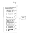
- Fig. 7 shows a schematic configuration of a programming device 10 according to the present invention, for returning a robot 1 to a waiting position.
- the programming device 10 includes: an attribute data providing part 10a for providing attribute data to each teaching position included in the teaching program, the attribute data representing whether each teaching position may be used for a teaching point of the returning program or not; a storing part 10b for storing at least one teaching program capable of being executed by the robot 1 and layout-information of the robot 1 and an object existing around the robot 1; a receiving part 10c for receiving data of the stop position, information for discriminating a teaching program stopped by the emergency stop and information of a block of the program executed when the program is stopped by the emergency stop; a selecting part 10d reading a teaching program from the storing part 10b corresponding to the information for discriminating, sequentially searching the teaching positions, from the block of the of the teaching program, in an executing direction of the program or a backward direction thereof, and selecting the teaching points used for the returning program based on the attribute data of the teaching positions;
- Fig. 1 shows a total configuration of one embodiment according to the invention.
- a numeral 1 denotes a robot (or a mechanism) having a work tool 2 attached to one end of an arm of the robot.
- the robot 1 is connected to a robot control device 3.
- the work tool 2 may be any kind of tool, the working tool 2 is considered to be a spot welding gun in this case.
- the robot control device 3 may be a normal type including a CPU, a memory, a servo controller, a communication interface for a network line, an input/output device for an external signal (an I/O board) and an interface for a teaching operation panel, etc., and, controls the robot 1 and the work tool 2 based on a teaching program for the robot.
- the teaching operation panel and other devices required for the motion of the work tool 2 (for example, a power supply for the spot welding gun) are not shown.
- a numeral 4 denotes a communication network line to which the control device 3 and the programming device 10 are connected.
- a personal computer may be used as the programming device.
- the personal computer may be a conventional offline programming/simulating device except that the computer has software for processing such as preparing a retuning program described below.
- the programming device 10 has a CPU, a memory, an interface for the network line and an input/output device for an external signal (an I/O board). Further, the programming device 10 has a keyboard 11 and a display 12 (for example, a LCD).
- the programming device 10 has the basic functions of an offline programming/simulating device: a function for determining and storing a work cell using a three-dimensional data and a layout data of the robot 1, the work tool 2, a workpiece, a jig for the workpiece and an object (not shown) around the robot; a function for making a robot program for operating the robot and the work tool by providing teaching data to the work cell; a function for simulating, in offline mode, the robot program or a external program transferred to the programming device; a function for judging the possibility of interference during operating the simulated program, by using the three-dimensional data and the layout data.
- these functions themselves are known, a detailed description of each of the functions is omitted.
- one or more robot programs capable of being executed by the system including the robot 1 are prepared in the programming device 10 and the necessary attribute data are added to each teaching position included in the program.
- the attribute data in this case are available data for forming a proper returning path when programming a returning program.
- a concrete example of the attribute data is described below.
- the robot program prepared in the programming device 10 may be made by using a programming function of the programming device 10. However, the robot program may be made by another offline programming device. Alternatively, the program used in the robot control device 3 as the teaching program may be transferred to the programming device 10 as the robot program.
- the above attribute data is usually not yet added to the teaching positions. Therefore, it is necessary to check characteristics of the teaching positions of the program, add necessary attribute data available for determining the returning path of the robot and store the attribute data.
- a character "g” is a parameter representing the propriety of the teaching position as the waiting position in the return program.
- a character "h” is a parameter indicating whether the work tool contacts the object or not.
- Fig. 2 shows an example of the attribute data (the 3-digit binary code) stored in the memory of the programming device 10 when the robot program for the spot welding includes thirteen teaching positions P1 - P13.
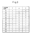
- Fig. 3 shows an example of the attribute data (the 3-digit binary code), similar to Fig. 2, when the robot program for the handling using a robot hand includes thirteen teaching positions Q1 - Q13.
- positions P1 and P13 may be the same, and/or positions Q1 and Q13 may be the same.
- the operator may read out the data of the teaching positions for indicating them on the display 12 and input a suitable code by using the keyboard 11, in order to add the above attribute data to the teaching positions.
- the teaching position may be corrected at need.
- the robot program is made by the programming device 10 offline, there often exist a difference of position between the predetermined layout data and the actual layout data of the operation system. Therefore, in order to correct the difference, the teaching position of the downloaded program is corrected.
- the robot program is executed to activate the actual system.
- a cycle time of the program and a history of the operation are recorded. If the system does not normally operate, the robot program is corrected such that the system normally operates.
- the robot program, the cycle time and the history are uploaded to the programming device 10.
- a plurality of cycle times and histories are recorded and uploaded to the offline programming system.
- the preparation for safely returning the robot 1 stopped by an error or the like to the waiting position, is thus completed.
- the operator directs, for example by operating the keyboard 11, the programming device 10 to return the robot to its waiting position. Then, the programming device 10 gets necessary data from the robot control device 3 to automatically make the returning program and transfers the returning program to the control device 3 after checking the safety of the program. After received the returning program, the robot control device 3 executes the returning program in order to safely and rapidly return the robot 1 to the waiting position.
- Fig. 4 shows a flowchart indicating steps carried out in a series of processes. A main point of each step of the flowchart will be described below.
- the teaching positions P1 - P13 added the attribute data shown in Fig. 2 are appropriately referred.
- the teaching positions Q1 - Q13 added the attribute data shown in Fig. 3 are referred using parentheses.
- the programming device 10 transfers a signal, for demanding information of the stop of the robot, to the robot control device 3.
- the robot control device 3 After receiving the demanding signal, the robot control device 3 sends information described below, as a reply to the signal, to the programming device 10.
- this data is for discriminating the robot program when the robot is stopped.
- One example of the data is a code name of the robot program.
- this data is for discriminating teaching positions before and after a point where the robot is stopped, in case that the point does not coincide with any of the teaching positions.
- the data is for discriminating the one teaching position where the robot is stopped.
- the data represents the elapsed time from the activation of the robot program to the stop of the robot by an error or the like.
- the programming device 10 reads out a corresponding robot program from the memory, based on the received "stopped program discriminating data", as well as the attribute data of the teaching positions and the data of the cycle time and the history.
- step S5 When the elapsed time is equal to or less than a half of the cycle time, the process progresses to step S5, otherwise, to step S6.
- the selecting part 10d described above sequentially searches the teaching positions before the point where the robot is stopped, from the stopped block of the robot program, in a backward direction of an executing direction of the robot program and lists all of the searched teaching positions as "teaching points capable of being used in the returning program".
- the teaching positions as shown in Fig. 2 (or Fig. 3), when the point where the robot is stopped is between points P6 and P7 (or Q6 and Q7), points P6, P5, P4, P3, P2 and P1 (Q6, Q5, Q4, Q3, Q2 and Q1) are listed.
- the selecting part 10d described above also sequentially searches the teaching positions after the point where the robot is stopped, from the stopped block of the robot program, in the executing direction or a forward direction of the robot program and, lists all of the searched teaching positions as "teaching points capable of being used in the returning program".
- the teaching positions as shown in Fig. 2 (or Fig. 3), when the point where the robot is stopped is between points P6 and P7 (or Q6 and Q7), points P7, P8, P9, P10, P11, P12 and P13 (Q7, Q8, Q9, Q10, Q11, Q12 and Q13) are listed.
- a primary check is carried out.
- the teaching point having the parameter "f" of the attribute data of the point equal to "0" is excluded.
- points P5 and P3 or Q6 are excluded and points P6, P4, P2 and P1 (or Q5 - Q1) are remained.
- points P7, P9 and P11 or no point are excluded and points P8, P10, P12 and P13 (or Q7 - Q13) are remained.
- One of the remained teaching points having, the parameter "g" of the attribute data of the point equal to "1”, is determined as a waiting position (a return position).
- point P1 or P13 or Q1 or Q13
- the waiting position is determined as the waiting position.
- two or more teaching points have the parameter "g" equal to "1”
- only one of them has to be determined as the waiting position by a suitable predetermined rule.
- a secondary check is carried out.
- the secondary check is based on the parameter "h" of the attribute data.
- the parameter "h” relates to the contact between the robot and the workpiece.
- the propriety of the teaching position in the robot program as the teaching point in the returning program may be judged by the parameter "h”, it is preferable that each teaching point is excluded, depending on whether the parameter "h" of the teaching point is equal to "0" or "1".
- the secondary check depends on whether the robot grips the workpiece or not.
- the robot gripping the workpiece occasionally cannot pass through a narrow path from point Q3 to point Q5, as the path is designed such that only the robot gripping nothing can pass the path.
- a detecting device or a sensor 5 is provided which is capable of detecting in real-time whether the robot 1 actually grips the workpiece.
- both teaching points having the parameter "h” equal to “1” and “0” may be selected as the teaching points of the returning program. Therefore, even on or after point Q6, if the robot does not grip the workpiece by some reasons, the teaching point having the parameter "h” equal to "0" may be selected.
- the teaching points used in the returning program stopped during operation may be determined.
- the returning program including a returning path for the robot is made by using the determined teaching points.
- the returning path of each of the above cases is determined as below:
- a straight line As for a form (a straight line or an arc, etc.) of the movement of the robot, "a straight line” is preferable, for example.
- another rule for selecting the form may be previously determined, based on the history of the execution of the stopped robot program. Further, it is preferable that constants regarding a velocity and an acceleration of the movement of the robot are automatically set to relatively low values, taking safety into consideration.
- a simulation of the prepared returning program is executed using an offline simulation function of the programming device 10.
- the interference judging part of the programming device judges whether interference between the robot and the peripheral devices around the robot occurs. When it is judged that the interference occurs, the process progresses to step S13, otherwise, to step S14.
- the returning program is corrected by the operator.
- the operator searches a cause of the interference by, for example, indicating the path of the returning program on the display 12, in order to correct the returning program. For example, to avoid interference, the operator may insert a new teaching point other than the teaching points included in the robot program or he may move the waiting position to another place. After the operator corrects the program, the process is returned to step S11.
- the process is once interrupted and a process from step S1 regarding the other robot is carried out so as to return, first, the other robot to a waiting position thereof. After that, the process of the robot 1 is restarted from step S11.
- the returning program is transferred to the robot control device 3.
- the robot control device 3 executes the received returning program to move the robot 1 to the waiting position, then, terminates the process.
- Fig. 5 shows examples of two returning paths of the returning program, as well as the robot programming path (P1 ⁇ P2 ⁇ P3 ⁇ ... ⁇ P12 ⁇ P13), in relation to the example of Fig. 2 (or the spot welding robot).
- a returning path RT1 ST1 ⁇ P4 ⁇ P2 ⁇ P1
- a returning path RT2 ST2 ⁇ P8 ⁇ P10 ⁇ P12 ⁇ P13
- step S4 As the position "between points P6 and P7" described above corresponds to the point ST2 in Fig. 5, an output in step S4 is "Yes". Therefore, the process is progressed to step S7 via step S6, whereby the returning path RT2 is selected and the returning program is executed. It would be recognized that the returning path thus selected allows the robot to safely and rapidly return to the waiting position.
- Fig. 6 shows examples of two returning paths of the returning program, as well as the robot programming path (Q1 ⁇ Q2 ⁇ Q3 ⁇ ... ⁇ Q12 ⁇ Q13), in relation to the example of Fig. 3 (or the handling robot).
- a returning path Q5 ⁇ Q4 ⁇ Q3 ⁇ Q2 ⁇ Q1
- another returning path Q7 ⁇ Q8 ⁇ Q9 ⁇ Q10 ⁇ Q11 ⁇ Q12 ⁇ Q13
- Q7 ⁇ Q8 ⁇ Q9 ⁇ Q10 ⁇ Q11 ⁇ Q12 ⁇ Q13 is selected when the robot is stopped at a position ST4 or in a second half of the cycle time.
- the robot may be safely and rapidly returned, to its waiting position, when the operation of a whole system, including the robot stopped by an error of the like during the operation, should be restarted from the first. Therefore, the deterioration of the productive efficiency caused by the error may be greatly reduced.
Landscapes
- Engineering & Computer Science (AREA)
- Robotics (AREA)
- Mechanical Engineering (AREA)
- Human Computer Interaction (AREA)
- Manufacturing & Machinery (AREA)
- Physics & Mathematics (AREA)
- General Physics & Mathematics (AREA)
- Automation & Control Theory (AREA)
- Numerical Control (AREA)
- Manipulator (AREA)
Applications Claiming Priority (1)
| Application Number | Priority Date | Filing Date | Title |
|---|---|---|---|
| JP2004191796A JP4027350B2 (ja) | 2004-06-29 | 2004-06-29 | ロボットの待機位置復帰プログラム作成装置 |
Publications (3)
| Publication Number | Publication Date |
|---|---|
| EP1625918A2 true EP1625918A2 (de) | 2006-02-15 |
| EP1625918A3 EP1625918A3 (de) | 2010-01-27 |
| EP1625918B1 EP1625918B1 (de) | 2011-10-05 |
Family
ID=35079342
Family Applications (1)
| Application Number | Title | Priority Date | Filing Date |
|---|---|---|---|
| EP05013686A Expired - Lifetime EP1625918B1 (de) | 2004-06-29 | 2005-06-24 | Programmiervorrichtung zum Zurückfahren eines Roboters in seiner Wartestellung |
Country Status (4)
| Country | Link |
|---|---|
| US (1) | US7774099B2 (de) |
| EP (1) | EP1625918B1 (de) |
| JP (1) | JP4027350B2 (de) |
| CN (1) | CN100408277C (de) |
Cited By (4)
| Publication number | Priority date | Publication date | Assignee | Title |
|---|---|---|---|---|
| WO2014056533A1 (en) | 2012-10-11 | 2014-04-17 | Abb Technology Ltd | A method and an apparatus for automatically generating a collision free return program for returning a robot from a stop position to a predefined restart position |
| EP2829366A3 (de) * | 2013-07-26 | 2015-03-25 | Kabushiki Kaisha Yaskawa Denki | Robotersystem, Roboterverwaltungscomputer für ein Robotersystem und Verfahren zur Verwaltung eines Robotersystems |
| DE102014224193B4 (de) | 2013-11-27 | 2019-09-19 | Infineon Technologies Ag | Verfahren und Vorrichtung zur Fehlerhandhabung eines Roboters |
| EP3812106A1 (de) * | 2019-10-23 | 2021-04-28 | Robert Bosch GmbH | Roboteranordnung, verfahren zum betreiben der roboteranordnung, computerprogramm sowie maschinenlesbares speichermedium |
Families Citing this family (64)
| Publication number | Priority date | Publication date | Assignee | Title |
|---|---|---|---|---|
| JP2008188722A (ja) * | 2007-02-06 | 2008-08-21 | Fanuc Ltd | ロボット制御装置 |
| JP4958608B2 (ja) * | 2007-04-06 | 2012-06-20 | 三菱電機株式会社 | ロボット制御装置、ロボット制御方法及びロボット搬送装置 |
| TWI336820B (en) * | 2007-07-24 | 2011-02-01 | Univ Da Yeh | A programming method combining static interaction with dynamic interaction |
| DE102008024950A1 (de) * | 2008-05-23 | 2009-11-26 | Kuka Roboter Gmbh | Verfahren und Vorrichtung zur Steuerung eines Manipulators |
| JP5228783B2 (ja) * | 2008-10-15 | 2013-07-03 | 株式会社デンソーウェーブ | ロボットの原点復帰装置 |
| DE112010000775B4 (de) * | 2009-02-12 | 2016-03-17 | Kyoto University | Industrierobotersystem |
| US9643316B2 (en) | 2009-10-27 | 2017-05-09 | Battelle Memorial Institute | Semi-autonomous multi-use robot system and method of operation |
| US8612072B2 (en) * | 2010-02-11 | 2013-12-17 | Teleflex Canada, Inc. | System for automatically instancing marine engines |
| US8340820B2 (en) * | 2010-02-26 | 2012-12-25 | Agilent Technologies, Inc. | Robot arm and method of controlling robot arm to avoid collisions |
| JP5647050B2 (ja) | 2011-03-25 | 2014-12-24 | 株式会社神戸製鋼所 | 溶接ロボットの一時停止解析装置および一時停止解析プログラム |
| US8843235B2 (en) | 2012-01-13 | 2014-09-23 | Toyota Motor Engineering & Manufacturing North America, Inc. | Robots, computer program products, and methods for trajectory plan optimization |
| US9014850B2 (en) | 2012-01-13 | 2015-04-21 | Toyota Motor Engineering & Manufacturing North America, Inc. | Methods and computer-program products for evaluating grasp patterns, and robots incorporating the same |
| US9014857B2 (en) | 2012-01-13 | 2015-04-21 | Toyota Motor Engineering & Manufacturing North America, Inc. | Methods and computer-program products for generating grasp patterns for use by a robot |
| DE102012101497B4 (de) * | 2012-02-24 | 2016-05-19 | Convergent Information Technologies Gmbh | Robotergestütztes Arbeitsverfahren |
| WO2013150597A1 (ja) | 2012-04-02 | 2013-10-10 | 株式会社安川電機 | ロボットシステム及びロボット制御装置 |
| DE102012008073A1 (de) * | 2012-04-24 | 2013-10-24 | Kuka Roboter Gmbh | Verfahren und Mittel zum Vorgeben und/oder Steuern eines Manipulatorprozesses |
| JP6110636B2 (ja) * | 2012-08-09 | 2017-04-05 | 日本電産サンキョー株式会社 | 産業用ロボット |
| WO2014024690A1 (ja) * | 2012-08-09 | 2014-02-13 | 日本電産サンキョー株式会社 | 産業用ロボット |
| CN103433925B (zh) * | 2013-07-31 | 2018-05-15 | 北京配天技术有限公司 | 机器人返回起始点的方法、运行方法、机器人及控制装置 |
| DE102013016019B3 (de) * | 2013-09-25 | 2015-03-19 | Festo Ag & Co. Kg | Verfahren zum Betreiben eines mehrgliedrigen Manipulators |
| EP2952299A1 (de) | 2014-06-05 | 2015-12-09 | Aldebaran Robotics | Standby-Modus für einen humanoiden Roboter |
| DE102014213262A1 (de) * | 2014-07-08 | 2016-01-14 | Kuka Roboter Gmbh | Maschine und Verfahren zum Betreiben einer Maschine |
| JP5905537B2 (ja) * | 2014-07-30 | 2016-04-20 | ファナック株式会社 | 教示操作盤が着脱可能なロボット制御装置 |
| JP5926344B2 (ja) | 2014-09-22 | 2016-05-25 | ファナック株式会社 | 非常停止時のロボットに関する不具合を防止するロボット制御装置 |
| JP2016064479A (ja) * | 2014-09-25 | 2016-04-28 | ファナック株式会社 | ロボット制御装置 |
| KR101941147B1 (ko) * | 2014-12-25 | 2019-04-12 | 카와사키 주코교 카부시키 카이샤 | 암형 로봇의 장애물 자동 회피방법 및 제어장치 |
| JP6034896B2 (ja) | 2015-02-24 | 2016-11-30 | ファナック株式会社 | 結線穴位置を補正できるワイヤ放電加工機およびワイヤ放電加工方法 |
| US9939799B2 (en) | 2015-04-30 | 2018-04-10 | Bae Systems Plc | Replacement path machining method and apparatus |
| US9939800B2 (en) * | 2015-04-30 | 2018-04-10 | Bae Systems Plc | Path following machining method and apparatus |
| CN105005306B (zh) * | 2015-07-24 | 2017-08-25 | 杭州德宝威智能科技有限公司 | 机器人表演中复位方法 |
| JP6411992B2 (ja) | 2015-12-25 | 2018-10-24 | ファナック株式会社 | ハンドル操作に応じてncプログラムを実行する機能において、プログラム実行状態を確認する手段を備えた数値制御装置 |
| CN105415375B (zh) * | 2016-01-02 | 2017-04-05 | 宁波市智能制造产业研究院 | 一种机器人离线编程系统 |
| CN105415376B (zh) * | 2016-01-10 | 2017-03-29 | 宁波市智能制造产业研究院 | 一种离线编程装置 |
| JP6816364B2 (ja) * | 2016-02-25 | 2021-01-20 | セイコーエプソン株式会社 | 制御装置、ロボット、及びロボットシステム |
| CN105690395B (zh) * | 2016-04-23 | 2017-09-19 | 宁波市智能制造产业研究院 | 工业机器人及其控制方法 |
| CN105835058B (zh) * | 2016-04-23 | 2017-10-27 | 福州环亚众志计算机有限公司 | 一种程序生成系统 |
| DE102016005026B3 (de) | 2016-04-24 | 2017-05-18 | Sami Haddadin | System und Verfahren zum Steuern eines Roboters |
| EP3252552A1 (de) * | 2016-06-02 | 2017-12-06 | Siemens Aktiengesellschaft | Automatisches freifahren eines werkzeugs nach einer betriebsunterbrechung |
| JP6858521B2 (ja) * | 2016-09-29 | 2021-04-14 | 川崎重工業株式会社 | ロボット復旧支援装置及びそれを備えるロボットシステム |
| JP6998660B2 (ja) * | 2017-02-21 | 2022-01-18 | 株式会社安川電機 | ロボットシミュレータ、ロボットシステム及びシミュレーション方法 |
| US10766140B2 (en) | 2017-04-13 | 2020-09-08 | Battelle Memorial Institute | Teach mode collision avoidance system and method for industrial robotic manipulators |
| CN107414837B (zh) * | 2017-09-13 | 2020-09-25 | 上海伟世通汽车电子系统有限公司 | 工业机器人非正常停机后安全自动回原位的方法及其系统 |
| JP1627364S (de) * | 2017-09-29 | 2019-03-25 | ||
| CN111417496B (zh) * | 2017-12-08 | 2023-03-28 | 株式会社富士 | 控制装置、工件作业装置、工件作业系统以及控制方法 |
| EP3542970A1 (de) * | 2018-03-20 | 2019-09-25 | Siemens Aktiengesellschaft | Verfahren, vorrichtung und system zur wiedergabe der bewegung eines roboters |
| US20210001484A1 (en) * | 2018-03-27 | 2021-01-07 | Productive Robotics, Inc. | Collaborative Robot System Incorporating Enhanced Human Interface |
| CN108873774A (zh) * | 2018-06-14 | 2018-11-23 | 合肥工业大学 | 一种vex机器人教学辅助控制系统及控制方法 |
| EP3614000B1 (de) * | 2018-08-24 | 2020-08-12 | Sick Ag | Verfahren und vorrichtung zur automatischen erkennung von greiferstellungen |
| TWI703022B (zh) * | 2018-09-26 | 2020-09-01 | 東元電機股份有限公司 | 應用於機械手臂之自動復歸控制系統與方法 |
| CN111002301A (zh) * | 2018-10-08 | 2020-04-14 | 东元电机股份有限公司 | 应用于机械手臂的自动复归控制系统与方法 |
| CN109240411B (zh) * | 2018-11-14 | 2020-12-08 | 广东奥科伟业科技发展有限公司 | 一种电子限位行程的自动修复方法 |
| US11981032B2 (en) | 2019-03-15 | 2024-05-14 | Omron Corporation | Robot control device, method and program for a recovery after an obstruction |
| JP6658985B1 (ja) * | 2019-05-17 | 2020-03-04 | 株式会社安川電機 | ロボットシステム、復帰プログラム生成装置、制御支援装置、制御装置、プログラム、復帰プログラムの生成方法及び復帰プログラムの出力方法 |
| JP7314824B2 (ja) * | 2019-05-17 | 2023-07-26 | 株式会社安川電機 | ロボットシステム、復帰プログラム生成装置、制御支援装置、制御装置、プログラム、復帰プログラムの生成方法及び復帰プログラムの出力方法 |
| CN111872609A (zh) * | 2019-08-27 | 2020-11-03 | 南京涵曦月自动化科技有限公司 | 一种用于焊接机器人系统的远程实时监控系统 |
| JP6898506B1 (ja) * | 2020-07-01 | 2021-07-07 | 株式会社安川電機 | 制御システム、ロボットシステム及び制御方法 |
| WO2022054768A1 (ja) * | 2020-09-11 | 2022-03-17 | ファナック株式会社 | ロボットシステム及びロボット動作の方法 |
| CN113232018B (zh) * | 2021-04-27 | 2022-05-10 | 成都飞机工业(集团)有限责任公司 | 一种机器人姿态快速复位的方法 |
| TWI766807B (zh) * | 2021-09-17 | 2022-06-01 | 財團法人精密機械研究發展中心 | 機械手臂的安全復位方法 |
| US12157230B2 (en) | 2021-10-04 | 2024-12-03 | Fanuc America Corporation | Intelligent clear path |
| CN114723313B (zh) * | 2022-04-22 | 2025-05-23 | 唐山松下产业机器有限公司 | 一种焊接机器人焊接理论周期确认方法及装置 |
| CN114942687B (zh) * | 2022-05-17 | 2024-04-05 | 上海芯钛信息科技有限公司 | 基于监控的复位安全机制、实现方法及复位电路 |
| CN117245646B (zh) * | 2022-12-12 | 2024-09-24 | 北京小米机器人技术有限公司 | 机器人及其调试方法、装置、存储介质 |
| WO2025263680A1 (ko) * | 2024-06-20 | 2025-12-26 | (주)필드로 | 험지주행이 가능한 모바일 주행로봇 및 이용한 서비스 방법 |
Citations (1)
| Publication number | Priority date | Publication date | Assignee | Title |
|---|---|---|---|---|
| EP0775557A1 (de) | 1994-08-02 | 1997-05-28 | Komatsu Ltd. | Vorrichtung zum zurückziehen eines unnormalen werkzeuges |
Family Cites Families (14)
| Publication number | Priority date | Publication date | Assignee | Title |
|---|---|---|---|---|
| US4398863A (en) * | 1981-05-15 | 1983-08-16 | Westinghouse Electric Corp. | Pick and place robot |
| JPS61131001A (ja) | 1984-11-29 | 1986-06-18 | Toyota Motor Corp | ロボツト用制御装置 |
| JPS62123504A (ja) * | 1985-11-22 | 1987-06-04 | Toshiba Mach Co Ltd | ロボツトの制御方法 |
| EP0266424B1 (de) * | 1986-03-20 | 1995-12-06 | Shin Meiwa Industry Co., Ltd. | Verfahren und anordnung zur regelung eines schweissroboters |
| JPH01146642A (ja) | 1987-12-03 | 1989-06-08 | Fanuc Ltd | 切削工具の停止制御装置 |
| US5760560A (en) * | 1993-10-21 | 1998-06-02 | Fanuc, Ltd. | Robot apparatus |
| KR0160692B1 (ko) * | 1995-05-04 | 1999-03-20 | 김광호 | 산업용 제어기의 절대 원점 찾는 방법 |
| JP3349652B2 (ja) * | 1997-07-16 | 2002-11-25 | 本田技研工業株式会社 | オフラインティーチング方法 |
| EP1671738B1 (de) * | 1998-12-16 | 2016-03-02 | Dengensha Manufacturing Company Limited | Widerstandsschweissmaschine |
| JP3459973B2 (ja) * | 1999-10-22 | 2003-10-27 | 川崎重工業株式会社 | 駆動制御方法および駆動制御装置 |
| JP3782679B2 (ja) * | 2001-05-09 | 2006-06-07 | ファナック株式会社 | 干渉回避装置 |
| JP2003048181A (ja) * | 2001-08-03 | 2003-02-18 | Denso Corp | 多関節型ロボット |
| JP3708083B2 (ja) * | 2003-02-28 | 2005-10-19 | ファナック株式会社 | ロボット教示装置 |
| JP3819883B2 (ja) * | 2003-08-27 | 2006-09-13 | ファナック株式会社 | ロボットプログラム位置修正装置 |
-
2004
- 2004-06-29 JP JP2004191796A patent/JP4027350B2/ja not_active Expired - Lifetime
-
2005
- 2005-06-24 EP EP05013686A patent/EP1625918B1/de not_active Expired - Lifetime
- 2005-06-24 US US11/165,349 patent/US7774099B2/en active Active
- 2005-06-29 CN CNB2005100798440A patent/CN100408277C/zh not_active Expired - Lifetime
Patent Citations (1)
| Publication number | Priority date | Publication date | Assignee | Title |
|---|---|---|---|---|
| EP0775557A1 (de) | 1994-08-02 | 1997-05-28 | Komatsu Ltd. | Vorrichtung zum zurückziehen eines unnormalen werkzeuges |
Cited By (5)
| Publication number | Priority date | Publication date | Assignee | Title |
|---|---|---|---|---|
| WO2014056533A1 (en) | 2012-10-11 | 2014-04-17 | Abb Technology Ltd | A method and an apparatus for automatically generating a collision free return program for returning a robot from a stop position to a predefined restart position |
| EP2829366A3 (de) * | 2013-07-26 | 2015-03-25 | Kabushiki Kaisha Yaskawa Denki | Robotersystem, Roboterverwaltungscomputer für ein Robotersystem und Verfahren zur Verwaltung eines Robotersystems |
| US9242371B2 (en) | 2013-07-26 | 2016-01-26 | Kabushiki Kaisha Yaskawa Denki | Robot system, robot management computer for a robot system, and method of managing a robot system |
| DE102014224193B4 (de) | 2013-11-27 | 2019-09-19 | Infineon Technologies Ag | Verfahren und Vorrichtung zur Fehlerhandhabung eines Roboters |
| EP3812106A1 (de) * | 2019-10-23 | 2021-04-28 | Robert Bosch GmbH | Roboteranordnung, verfahren zum betreiben der roboteranordnung, computerprogramm sowie maschinenlesbares speichermedium |
Also Published As
| Publication number | Publication date |
|---|---|
| JP2006012074A (ja) | 2006-01-12 |
| US7774099B2 (en) | 2010-08-10 |
| CN1715010A (zh) | 2006-01-04 |
| EP1625918B1 (de) | 2011-10-05 |
| US20060009878A1 (en) | 2006-01-12 |
| CN100408277C (zh) | 2008-08-06 |
| EP1625918A3 (de) | 2010-01-27 |
| JP4027350B2 (ja) | 2007-12-26 |
Similar Documents
| Publication | Publication Date | Title |
|---|---|---|
| EP1625918B1 (de) | Programmiervorrichtung zum Zurückfahren eines Roboters in seiner Wartestellung | |
| CN100460161C (zh) | 机械手控制装置及机械手控制方法 | |
| US20140364989A1 (en) | Controller for controlling machine tool and robot | |
| EP0766154B1 (de) | Numerisch gesteuerte Werkzeugmaschine und Verfahren | |
| US20050107919A1 (en) | Operation program preparation device | |
| US10940583B2 (en) | Method and computer program for producing a graphical user interface of a manipulator program | |
| JPH01308185A (ja) | モータ制御装置 | |
| US12377543B2 (en) | Path planning during execution of robot control | |
| US5323308A (en) | Programmable control system | |
| JP2004334914A (ja) | 数値制御装置 | |
| JPH0957576A (ja) | 生産セル | |
| JPH02172646A (ja) | 数値制御装置 | |
| CN111488270A (zh) | 机器人离线程序的干涉区指令检测方法、系统及存储介质 | |
| JP7846602B2 (ja) | セルコントローラ | |
| EP4610003A1 (de) | Robotersteuerung und verfahren zum vergleichen von steuerungssoftware vor und nach der aktualisierung | |
| JP7602092B1 (ja) | Nc工作機械用の加工実績管理システム、サーバ装置、および加工状況監視プログラム | |
| Praehofer et al. | Supervising manufacturing system operation by DEVS-based intelligent control | |
| JP5445233B2 (ja) | ロボットのコントローラ | |
| JPH07136975A (ja) | 複数ロボットシステム | |
| JP2024134563A (ja) | 工作機械 | |
| JPH0736525A (ja) | コンピュータシステム | |
| JPH01112303A (ja) | プログラマブルコントローラシステム | |
| KR19990031694A (ko) | 공작기계의 가공공구 확인방법 | |
| JP2000322120A (ja) | プログラムテスト機能を備えた加工制御装置 | |
| JPH0682291B2 (ja) | 数値制御装置 |
Legal Events
| Date | Code | Title | Description |
|---|---|---|---|
| PUAI | Public reference made under article 153(3) epc to a published international application that has entered the european phase |
Free format text: ORIGINAL CODE: 0009012 |
|
| AK | Designated contracting states |
Kind code of ref document: A2 Designated state(s): AT BE BG CH CY CZ DE DK EE ES FI FR GB GR HU IE IS IT LI LT LU MC NL PL PT RO SE SI SK TR |
|
| AX | Request for extension of the european patent |
Extension state: AL BA HR LV MK YU |
|
| PUAL | Search report despatched |
Free format text: ORIGINAL CODE: 0009013 |
|
| AK | Designated contracting states |
Kind code of ref document: A3 Designated state(s): AT BE BG CH CY CZ DE DK EE ES FI FR GB GR HU IE IS IT LI LT LU MC NL PL PT RO SE SI SK TR |
|
| AX | Request for extension of the european patent |
Extension state: AL BA HR LV MK YU |
|
| RIC1 | Information provided on ipc code assigned before grant |
Ipc: B25J 9/16 20060101AFI20051222BHEP Ipc: G05B 19/4067 20060101ALI20091223BHEP |
|
| 17P | Request for examination filed |
Effective date: 20100127 |
|
| 17Q | First examination report despatched |
Effective date: 20100324 |
|
| AKX | Designation fees paid |
Designated state(s): DE |
|
| GRAP | Despatch of communication of intention to grant a patent |
Free format text: ORIGINAL CODE: EPIDOSNIGR1 |
|
| GRAS | Grant fee paid |
Free format text: ORIGINAL CODE: EPIDOSNIGR3 |
|
| RAP1 | Party data changed (applicant data changed or rights of an application transferred) |
Owner name: FANUC CORPORATION |
|
| RIN1 | Information on inventor provided before grant (corrected) |
Inventor name: KOBAYASHI, HIROHIKO Inventor name: NAGATSUKA, YOSHIHARU |
|
| GRAA | (expected) grant |
Free format text: ORIGINAL CODE: 0009210 |
|
| AK | Designated contracting states |
Kind code of ref document: B1 Designated state(s): DE |
|
| REG | Reference to a national code |
Ref country code: DE Ref legal event code: R082 Ref document number: 602005030319 Country of ref document: DE Representative=s name: WUESTHOFF & WUESTHOFF PATENT- UND RECHTSANWAEL, DE |
|
| REG | Reference to a national code |
Ref country code: DE Ref legal event code: R096 Ref document number: 602005030319 Country of ref document: DE Effective date: 20111215 |
|
| REG | Reference to a national code |
Ref country code: DE Ref legal event code: R082 Ref document number: 602005030319 Country of ref document: DE Representative=s name: WUESTHOFF & WUESTHOFF PATENT- UND RECHTSANWAEL, DE Effective date: 20111116 Ref country code: DE Ref legal event code: R081 Ref document number: 602005030319 Country of ref document: DE Owner name: FANUC CORPORATION, JP Free format text: FORMER OWNER: FANUC CORPORATION, OSHINO-MURA, JP Effective date: 20111116 Ref country code: DE Ref legal event code: R081 Ref document number: 602005030319 Country of ref document: DE Owner name: FANUC CORP., JP Free format text: FORMER OWNER: FANUC LTD., YAMANASHI, JP Effective date: 20111021 Ref country code: DE Ref legal event code: R081 Ref document number: 602005030319 Country of ref document: DE Owner name: FANUC CORP., JP Free format text: FORMER OWNER: FANUC CORPORATION, YAMANASHI, JP Effective date: 20111116 Ref country code: DE Ref legal event code: R081 Ref document number: 602005030319 Country of ref document: DE Owner name: FANUC CORPORATION, JP Free format text: FORMER OWNER: FANUC LTD., YAMANASHI, JP Effective date: 20111021 Ref country code: DE Ref legal event code: R081 Ref document number: 602005030319 Country of ref document: DE Owner name: FANUC CORPORATION, OSHINO-MURA, JP Free format text: FORMER OWNER: FANUC CORPORATION, OSHINO-MURA, JP Effective date: 20111116 Ref country code: DE Ref legal event code: R081 Ref document number: 602005030319 Country of ref document: DE Owner name: FANUC CORPORATION, OSHINO-MURA, JP Free format text: FORMER OWNER: FANUC LTD., YAMANASHI, JP Effective date: 20111021 Ref country code: DE Ref legal event code: R082 Ref document number: 602005030319 Country of ref document: DE Representative=s name: WUESTHOFF & WUESTHOFF, PATENTANWAELTE PARTG MB, DE Effective date: 20111116 Ref country code: DE Ref legal event code: R081 Ref document number: 602005030319 Country of ref document: DE Owner name: FANUC CORPORATION, OSHINO-MURA, JP Free format text: FORMER OWNER: FANUC CORPORATION, OSHINO-MURA, YAMANASHI, JP Effective date: 20111116 Ref country code: DE Ref legal event code: R081 Ref document number: 602005030319 Country of ref document: DE Owner name: FANUC CORPORATION, OSHINO-MURA, JP Free format text: FORMER OWNER: FANUC CORPORATION, YAMANASHI, JP Effective date: 20111116 |
|
| REG | Reference to a national code |
Ref country code: DE Ref legal event code: R082 Ref document number: 602005030319 Country of ref document: DE Representative=s name: WUESTHOFF & WUESTHOFF PATENT- UND RECHTSANWAEL, DE Effective date: 20120202 Ref country code: DE Ref legal event code: R081 Ref document number: 602005030319 Country of ref document: DE Owner name: FANUC CORPORATION, JP Free format text: FORMER OWNER: FANUC CORP., YAMANASHI, JP Effective date: 20120202 Ref country code: DE Ref legal event code: R081 Ref document number: 602005030319 Country of ref document: DE Owner name: FANUC CORPORATION, OSHINO-MURA, JP Free format text: FORMER OWNER: FANUC CORP., YAMANASHI, JP Effective date: 20120202 Ref country code: DE Ref legal event code: R082 Ref document number: 602005030319 Country of ref document: DE Representative=s name: WUESTHOFF & WUESTHOFF, PATENTANWAELTE PARTG MB, DE Effective date: 20120202 |
|
| PLBE | No opposition filed within time limit |
Free format text: ORIGINAL CODE: 0009261 |
|
| STAA | Information on the status of an ep patent application or granted ep patent |
Free format text: STATUS: NO OPPOSITION FILED WITHIN TIME LIMIT |
|
| 26N | No opposition filed |
Effective date: 20120706 |
|
| REG | Reference to a national code |
Ref country code: DE Ref legal event code: R097 Ref document number: 602005030319 Country of ref document: DE Effective date: 20120706 |
|
| PGFP | Annual fee paid to national office [announced via postgrant information from national office to epo] |
Ref country code: DE Payment date: 20240521 Year of fee payment: 20 |
|
| REG | Reference to a national code |
Ref country code: DE Ref legal event code: R071 Ref document number: 602005030319 Country of ref document: DE |