EP1624934B1 - Formation de faisceaux acoustiques en reseaux phases comprenant de nombreux elements transducteurs - Google Patents
Formation de faisceaux acoustiques en reseaux phases comprenant de nombreux elements transducteurs Download PDFInfo
- Publication number
- EP1624934B1 EP1624934B1 EP04732152A EP04732152A EP1624934B1 EP 1624934 B1 EP1624934 B1 EP 1624934B1 EP 04732152 A EP04732152 A EP 04732152A EP 04732152 A EP04732152 A EP 04732152A EP 1624934 B1 EP1624934 B1 EP 1624934B1
- Authority
- EP
- European Patent Office
- Prior art keywords
- transducer elements
- transducer
- controller
- switch
- transducer array
- Prior art date
- Legal status (The legal status is an assumption and is not a legal conclusion. Google has not performed a legal analysis and makes no representation as to the accuracy of the status listed.)
- Active
Links
Images

Classifications
-
- G—PHYSICS
- G10—MUSICAL INSTRUMENTS; ACOUSTICS
- G10K—SOUND-PRODUCING DEVICES; METHODS OR DEVICES FOR PROTECTING AGAINST, OR FOR DAMPING, NOISE OR OTHER ACOUSTIC WAVES IN GENERAL; ACOUSTICS NOT OTHERWISE PROVIDED FOR
- G10K11/00—Methods or devices for transmitting, conducting or directing sound in general; Methods or devices for protecting against, or for damping, noise or other acoustic waves in general
- G10K11/18—Methods or devices for transmitting, conducting or directing sound
- G10K11/26—Sound-focusing or directing, e.g. scanning
- G10K11/34—Sound-focusing or directing, e.g. scanning using electrical steering of transducer arrays, e.g. beam steering
- G10K11/341—Circuits therefor
- G10K11/346—Circuits therefor using phase variation
-
- A—HUMAN NECESSITIES
- A61—MEDICAL OR VETERINARY SCIENCE; HYGIENE
- A61N—ELECTROTHERAPY; MAGNETOTHERAPY; RADIATION THERAPY; ULTRASOUND THERAPY
- A61N7/00—Ultrasound therapy
- A61N7/02—Localised ultrasound hyperthermia
-
- A—HUMAN NECESSITIES
- A61—MEDICAL OR VETERINARY SCIENCE; HYGIENE
- A61N—ELECTROTHERAPY; MAGNETOTHERAPY; RADIATION THERAPY; ULTRASOUND THERAPY
- A61N7/00—Ultrasound therapy
- A61N2007/0056—Beam shaping elements
- A61N2007/0065—Concave transducers
-
- A—HUMAN NECESSITIES
- A61—MEDICAL OR VETERINARY SCIENCE; HYGIENE
- A61N—ELECTROTHERAPY; MAGNETOTHERAPY; RADIATION THERAPY; ULTRASOUND THERAPY
- A61N7/00—Ultrasound therapy
- A61N2007/0078—Ultrasound therapy with multiple treatment transducers
-
- A—HUMAN NECESSITIES
- A61—MEDICAL OR VETERINARY SCIENCE; HYGIENE
- A61N—ELECTROTHERAPY; MAGNETOTHERAPY; RADIATION THERAPY; ULTRASOUND THERAPY
- A61N7/00—Ultrasound therapy
- A61N2007/0086—Beam steering
- A61N2007/0091—Beam steering with moving parts, e.g. transducers, lenses, reflectors
-
- A—HUMAN NECESSITIES
- A61—MEDICAL OR VETERINARY SCIENCE; HYGIENE
- A61N—ELECTROTHERAPY; MAGNETOTHERAPY; RADIATION THERAPY; ULTRASOUND THERAPY
- A61N7/00—Ultrasound therapy
- A61N2007/0086—Beam steering
- A61N2007/0095—Beam steering by modifying an excitation signal
Definitions
- This invention relates to systems for delivering acoustic energy into a body, and more particularly to systems for focusing acoustic energy transmitted from a transducer array including a large number of transducer elements.
- Focused ultrasound systems have been suggested for delivering acoustic energy into a tissue region within a patient, such as a cancerous or benign tumor, to coagulate or otherwise treat the tissue region with thermal energy.
- a piezoelectric transducer located outside the patient's body may be used to focus high intensity acoustic waves, such as ultrasonic waves (acoustic waves with a frequency greater than about twenty kilohertz (20 kHz)), at an internal tissue region of a patient to treat the tissue region.
- the acoustic waves may be used to ablate a tumor, thereby eliminating the need for invasive surgery.
- Such an acoustic transducer system is disclosed in U.S. Patent No. 4,865,042 issued to Umemura et al .
- a "focal zone” the volume of tissue treated when the acoustic energy is focused into a tissue region
- "focal depth” the distance from the transducer to the focal zone
- tissue aberrations that may be caused by intervening tissue between the transducer and the tissue region.
- transducer elements having a width or other maximum cross-section of less than one millimeter.
- the total number of such transducer elements required would become very large, i.e., requiring hundreds or even thousands of transducer elements.
- the problem with providing so many transducer elements is that individual sets of drive signals must be delivered to each transducer element in order for the transducer elements to transmit acoustic energy.
- hundreds or thousands of wires or cables would be required to deliver the drive signals to the transducer elements.
- the resulting system would be complicated and expensive to implement.
- the invention is directed to systems for delivering acoustic energy from a transducer array as defined in claim 1, and more particularly to systems for focusing and/or steering acoustic energy from a transducer array including a large number of transducer elements, preferably into a body of a patient for ablating or otherwise treating tissue with the patient's body.
- a system for focusing acoustic energy towards a target region that includes a transducer array, a controller for providing drive signals to the transducer array, and a switch.
- the transducer array includes a plurality of "n” transducer elements
- the controller includes a plurality of "m” output channels providing sets of drive signals having respective phase shift values, "m” being less than "n.”
- the switch e.g., a cross-point matrix or a multistage interconnection network (“MIN”), is coupled to the output channels of the controller and to the transducer elements.
- the switch is configured for connecting output channels to respective transducer elements in order to provide respective sets of drive signals to the respective transducer elements, whereby acoustic energy transmitted by the transducer array may be focused in a desired manner.
- the controller may be coupled to the switch for configuring the switch in order to connect the output channels to the respective transducer elements.
- Using a switch with "m" drive channels to control drive signals provided to a relatively large number of "n” transducer elements may substantially minimize the complexity of the system, since relatively few drive channels may be needed for a relatively large number of transducer elements. It may also allow complex phase patterns to be created in a sub-set of transducer elements or using the entire transducer array, while using a limited number of input drive channels. In addition, because a limited number of drive channels deliver power to a relatively large number of transducer elements, the drive channels may be loaded substantially evenly, as desired for statistically even phase distribution.
- the controller may be configured for assigning each of the transducer elements to a respective output channel based upon one or more parameters related to a course of treatment of a target tissue region using the transducer array.
- the controller may assign the transducer elements to respective output channels based upon a size of a focal zone within the target region, a shape of the focal zone, axial and/or angular location of the focal zone, impedances of the transducer elements, and/or tissue aberrations caused by tissue between the transducer array and the focal zone.
- a transducer array for delivering acoustic energy to a target region that includes a plurality of "n" transducer elements arranged on one or more substrates, and a switch coupled to the transducer elements.
- the switch may be coupled to the substrate(s), e.g., via electrical connections that are flexible enough not to impact substantially the acoustic characteristics of the transducer array.
- the switch may include a plurality of "m” input channels and “n” output channels coupled to the transducer elements, "m” being less than "n.”
- Each input channel of the switch may be connectable to a controller for transferring only selected drive signals including respective phase shift values, the switch configured to couple the input channels to respective transducer elements in order to provide drive signals to the respective transducer elements, whereby acoustic energy transmitted by the transducer elements may be focused in a desired manner.
- the transducer array may include a single substrate, and the switch may be mounted to the substrate. Alternatively, the transducer array may include a plurality of substrates that may be fixed or adjustable physically relative to one another.
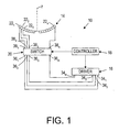
- FIGS. 1 and 2 depict an exemplary embodiment of a focused ultrasound system 10, including a transducer array 14, a driver 16, a controller 18, and a switch 20, in accordance with the invention.
- the transducer array 14 may deliver acoustic energy represented by acoustic beam 15 into a target region 92, e.g., a benign or malignant tumor or other tissue volume, within a patient's body 90, to ablate or otherwise treat tissue within the target region 92.
- the switch 20 connects the transducer array 14 to the driver 16 and/or to the controller 18 in order to steer and/or focus the acoustic energy transmitted by the transducer array 14 in a desired manner.
- the transducer array 14 generally includes multiple transducer elements 22 arranged in a pattern on a substrate 24.
- the substrate 24 may be a frame, a planar or curved structure, and the like, onto which the transducer elements 22 may be mounted or otherwise provided.
- the transducer array 14 may have a concave or bowl shape, such as a "spherical cap" shape, i.e., having a substantially constant radius of curvature such that the transducer array 14 has an inside surface defining a portion of a sphere, although alternatively, the substrate 24 may define a non-spherical surface.
- the transducer array 14 may have an outer diameter between about eight and sixteen centimeters (8-16 cm), and a radius of curvature between about eight and twenty centimeters (8-20 cm).
- the transducer array 14 may have a substantially flat configuration (not shown), may include an outer perimeter that is generally circular, and/or may have a square, linear, hexagonal or other symmetrical or asymmetrical shape (not shown).
- the transducer array 14 may be divided into any desired number "n" of transducer elements 22 1 , 22 2 22 3 , ... 22 n , as seen in FIG. 1 , and/or into a plurality of subsets of transducer elements, each with a plurality of transducer elements.
- the transducer array 14 may be divided into concentric rings and/or circumferential sectors to provide the transducer elements 22.
- the transducer array 14 may include between ten and forty (10-40) rings and between four and sixteen (4-16) sectors.
- the transducer 14 may include transducer elements 22 having a variety of geometric shapes, such as hexagons, triangles, circles, squares, and the like (not shown).
- the transducer elements 22 may be disposed about a central axis "z," preferably but not necessarily, in a substantially uniform or symmetrical configuration. Preferably, although not necessarily, the transducer elements 22 have substantially the same surface area as one another and/or may have similar or different sizes and shapes than one another. Additional information on the construction of transducer arrays appropriate for use with the invention may be found, for example, in U.S. Patent No. 2002/0193681 .
- a transducer array 14 in accordance with the invention may include many transducer elements, e.g., hundreds or thousands of transducer elements built as a single dish, or as an assembly of many individual tiles, assembled into a structure to provide a combined array.
- the transducer array 14 includes between about two hundred and ten thousand (200-10,000) transducer elements 22.
- the transducer elements 22 may have a width, diameter, or other maximum cross-sectional dimension across their surface area that is on the order of the wavelength of the acoustic energy that is transmitted by the transducer elements 22.
- the transducer elements 22 may have a cross-sectional dimension between about 0.8 and seven millimeters (0.8-7 mm), which are on the order of the wavelength of ultrasonic energy between about two and 0.2 Megahertz (2-0.2 MHz), respectively.
- the specific number of transducer elements and their sizes, however, is not important to the invention, and the systems discussed herein may be applicable to a transducer array 14 including a variety of different configurations of transducer elements 22.
- the driver 16 and/or the controller 18 may be coupled to the transducer array 14 via the switch 20 for causing the transducer elements 22 to transmit acoustic energy.
- the driver 16 includes an oscillator and/or other component(s) (not shown) enabling the driver 16 to generate electrical drive signals, which may be controlled by the controller 18.
- the driver 16 may generate drive signals in the ultrasound frequency spectrum that may be as low as twenty kilohertz (20 kHz), and that typically range from about 0.3 to three Megahertz (0.3-3.0 MHz).
- the driver 16 provides radio frequency (RF) drive signals, for example, between about 0.3-3.0 MHz, and more preferably between about 0.5-2.5 MHz.
- RF radio frequency
- the transducer elements 22 convert the electrical drive signals into vibrational energy, as represented by the acoustic beam 15.
- Exemplary drivers and/or controllers that may be used to generate sets of drive signals are disclosed in U.S. Patent No. 6,506,154 .
- the driver 16 and/or controller 18 may be separate from or integral components of the transducer array 14, and/or may be separate components from or integral with one another. It will be appreciated by one skilled in the art that the operations performed by the driver 16 and/or controller 18 may be performed by one or more controllers, processors, and/or other electronic components, including software or hardware components.
- the driver 16 includes a number "m” of output channels 34 that provide respective sets of drive signals (s 1 , s 2 , s 3 , ... s m ) having respective phase shift values ( ⁇ 1 , ⁇ 2 , ⁇ 3 , ... ⁇ m ).
- the number “m” of output channels 34 is generally substantially less than the number "n” of transducer elements 22, and preferably "m” is orders of magnitude smaller than "n.”
- "n"/"m” could be between about ten and one hundred (10-100), or even more than one hundred (100).
- the switch 20 generally includes an "m” number of inputs 36, an "n” number of outputs 38, and a plurality of switches (not shown) therein.
- the "m” output channels 34 from the driver 16 may be coupled to the "m” inputs 36 of the switch 20, respectively, and the "n” outputs 38 of the switch 20 may be coupled to the "n” transducer elements 22, respectively.
- the switch 20 may allow respective inputs 36 to be selectively connected to one or more respective outputs 38, thereby delivering sets of drive signals with different phase shift values to respective transducer elements 22.
- the switch 20 may be a cross-point matrix, a multistage interconnection network ("MIN"), or other switching device enabling multiple inputs to be selectively connected to one or more respective outputs.
- the switch 20 is mounted to the transducer array 14, e.g., to the substrate 24 opposite the transducer elements 22, as shown in FIG. 2 .
- Wires, cables, conductive paths, or other conductors may extend between the outputs 38 of the switch 20 and respective transducer elements 22, e.g., along the substrate 24 or otherwise contained within the transducer array 14.
- the leads should provide electrical connectivity, while mechanically isolating the transducer vibrating elements from the substrate 24.
- the switch 20 may be mounted in close proximity to the transducer array 14, i.e., not directly mounted to the substrate 24.
- Wires or other leads may extend from the inputs 36 of the switch 20 to the driver 16. This arrangement may substantially simplify wiring of the transducer array 14, since only "m” leads are required for the cable(s) connecting the transducer array 14 to the driver 16, rather than "n” leads, as would be required if each transducer element 22 were separately connected to the driver 16.
- the switch 20 is used in conjunction with magnetic resonance imaging ("MRI"), parts of the switch 20, including any leads should be made from nonmagnetic materials, as is well known to those skilled in the art.
- the leads may include one or more connectors (not shown) for detachably connecting them to any of the components described herein.
- the controller 18 may control the driver 16, e.g., to control one or more characteristics of the drive signals generated by the driver 16. For example, the controller 18 may control an amplitude of the drive signals, and, consequently, the intensity or power of the acoustic waves transmitted by the transducer 14, and/or the phase allocation to each of the "m" leads 34 leaving the driver 16.
- the controller 18 may also control and/or assign phase shift values to the drive signals in order to steer and/or focus the acoustic energy in a desired manner.
- the controller 18 may divide a full cycle (360° or 2 ⁇ radians) by the number of output channels 34 of the driver 16 and assign sequential phase shift values, e.g., between 0° and 360° to the sets of drive signals.
- the controller 18 may assign phase shift values using other methodologies, and cause the driver 16 to generate sets of drive signals based upon the assigned phase shift values.
- controller 18 may be configured to generate one or more tables relating sets of drive signals to the transducer elements 22 that may be used by the system 10.
- the controller 18 may include one or more processors (not shown) for generating the data for the tables, and/or memory (also not shown) for storing the one or more tables.
- the controller 18 may generate respective desired phase shift values for the transducer elements 22 based upon parameters for a particular treatment, and create a first table of desired phase shift values for the transducer elements 22.
- the data in the first table may be based upon a desired focal depth, a desired focal zone shape, compensation for tissue aberrations encountered during a particular treatment, compensation for variances in the relative impedance of the transducer elements, and/or compensation for geometric inaccuracies in positioning the transducer elements 22 relative to one another on the transducer array 14.
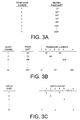
- a hypothetical set of desired phase shift values for a transducer array including "n" elements is shown in FIG. 3A .
- separate tables may be generated for one or more of these parameters, e.g., for different beam paths, focal zone locations, and/or focal depths.
- one or more sets of tables may be loaded, e.g., to reconfigure the switch 20 during a procedure. This may provide the controller 18 with even greater flexibility to switch steering and focusing dynamically.
- the controller 18 may assign phase shift values to each of the transducer elements 22 based upon a desired location for the focal zone 17 of the transducer array 14. For example, the controller 18 may assign phase shift values to transducer elements 22 based upon their circumferential location around the central axis "z" and/or their radial distance from the central axis "z.” These phase shift values may change the size and/or shape of the resulting focal zone 17, and/or may adjust the focal depth. In addition, the controller 18 may assign phase shift values to the transducer elements 22 that move the focal zone laterally relative to the central axis "z," i.e., to steer the focal zone away from the central axis "z,” and/or to generate multiple focal zones simultaneously. Exemplary systems for achieving such steering are disclosed in U.S. Patent No. 6,506,154 .
- the controller 18 may compensate for tissue aberrations, i.e., phase shifts that may occur due to the acoustic energy from respective transducer elements 22 traveling along different acoustic paths having different densities, e.g., when the acoustic energy passes through different tissue structures.
- the controller 18 may analyze an acoustic path from each of the transducer elements 22 through intervening tissue structures to the target region 92, e.g., using magnetic resonance imaging, ultrasound imaging, and the like.
- Exemplary systems for compensating for tissue aberrations are disclosed in U.S. Patent Nos. 6,666,833 and 6,705,994 .
- phase shift values for compensating for tissue aberrations may be added to any other phase shift values assigned by the controller 18, e.g., those desired to control the size and/or location of the resulting focal zone, to provide phase corrections correcting for physical tolerances in the transducer structure, and/or to compensate for impedance variations between the different elements.
- the controller 18 may assign sets of drive signals to the transducer elements 22 to create a second table of assigned drive signal-transducer element relationships. For example, the controller 18 may compare the phase shift values of the sets of drive signals to the desired phase shift values for the transducer elements 22, and assign each of the transducer elements 22 to a set of drive signals that has a phase shift value that approximates the desired phase shift value for the respective transducer element. The controller 18 may round the desired phase shift value for each of the transducer elements 22 off to the nearest phase shift value corresponding to one of the sets of drive signals.
- the desired phase shift values could be truncated or associated with respective sets of drive signals using other methodologies.
- An exemplary table showing transducer elements assigned to respective output channels, and consequently, respective phase shift values is shown in FIG. 3B .
- the controller 18 may generate a third table to control the switch 20, e.g., based upon the drive signal-transducer element assignments in the second table. For example, if the switch 20 is a cross-point matrix, the third table may instruct the cross-point matrix to configure its switches in a particular manner to connect the inputs 36 to respective outputs 38 in order to connect the transducer elements 22 to the output channels 34 corresponding to their assigned sets of drive signals.
- the controller 18 may control the switch 20 directly, or the switch 20 may include its own controller (not shown).
- An exemplary table identifying inputs and outputs of a switch to connect to one another is shown in FIG. 3B , based upon the data from FIGS. 3A and 3B discussed above.
- the controller 18 may also control a physical position or orientation of the transducer array 14.
- the system 10 may include a mechanical positioner 48 connected to the transducer array 14 that may move the transducer array 14 in one or more dimensions, and preferably in any of three orthogonal directions.
- Exemplary transducers and positioning systems are disclosed in U.S. Patent Nos. 6,419,648 , 6,613,004 and 6,582,381 .
- the transducer array 14 may be focused electronically, mechanically, or using a combination of the two, and/or the focus zone may be moved within the target 92 electronically, mechanically, or using a combination of the two.
- the transducer array 14 may be mounted within a casing or chamber 40 filled with degassed water or similar acoustically propagating fluid.
- the chamber 40 may be located within a table 42 upon which a patient 90 may be disposed, or within a fluid-filled bag mounted on a movable arm that may be placed against a patient's body (not shown).
- the top of the table 42 generally includes a flexible membrane 44 that is substantially transparent to ultrasound, such as mylar, polyvinyl chloride (PVC), or other suitable plastic material.
- a fluid-filled bag 46 may be provided on the membrane 44 that may conform easily to the contours of the patient 90 disposed on the table 42, thereby acoustically coupling the patient 90 to the transducer array 14 within the chamber 40.
- acoustic gel, water, or other fluid may be provided between the patient 90 and the membrane 44 to facilitate further acoustic coupling between the transducer array 14 and the patient 90.
- the system 10 may include an imaging device (not shown) for monitoring the use of the system during treatment of a patient.
- the system 10 may be placed within a magnetic resonance imaging (MRI) system, such as that disclosed in U.S. Patent Nos. 5,247,935 , 5,291,890 , 5,368,031 , 5,368,032 , 5,443,068 , 5,307,812 , 5,323,779 , and 5,327,884
- MRI magnetic resonance imaging
- an acoustic imaging device may be provided, or the transducer array 14 itself may be used for imaging.
- a patient 90 may be disposed on the table 42 with water, ultrasonic conducting gel, and the like (not shown) applied between the patient 90 and the bag 46 or membrane 44, thereby acoustically coupling the patient 90 with the transducer array 14.
- the transducer array 14 may be oriented generally towards a target tissue region 92, e.g. within a tissue structure, such as a cancerous or benign tumor within an organ, e.g., a liver, kidney, pancreas, uterus or brain.
- the acoustic path from the transducer array 14 to the target tissue region 92 may be analyzed, e.g., using MRI or ultrasound imaging, as explained above.
- the acoustic path from each of the transducer elements 22 to the target tissue region 92 may be analyzed to determine tissue types or other characteristics that may affect the speed of the acoustic energy passing through intervening tissue between the transducer elements 22 and the target tissue region 92.
- Phase shift values may be determined for each of the transducer elements 22 to compensate for these variations in speed in order to maintain the focus of the acoustic energy substantially at the desired focal zone 17.
- individual transducer elements 22 may be deactivated (e.g., have their amplitude set to zero (0)) in order to prevent acoustic energy from being transmitted by the relevant transducer elements 22.
- the controller 18 may be instructed to generate a treatment procedure, which may involve a single or multiple "sonications" (i.e., finite time periods during which the transducer array 14 is activated to deliver acoustic energy to a focal zone at a particular location within the target tissue region 92).
- the controller 18 and/or the operator may set the number and duration of sonications to be used to treat the target tissue region 92.
- the controller 18 may generate the tables described above and/or otherwise instruct the switch 20 in order to connect the output channels 34 of the driver 16 to respective transducer elements 22.
- the controller 18 may assign phase shift values to the sets of drive signals that will be provided at each of the output channels 34 of the driver 16.
- the phase shift values of the sets of drive signals may be fixed, e.g., based upon phase errors required to achieve a predefined focus quality.
- continuous wave (CW) acoustic beam forming in phased arrays requires the ability to control phase errors between different transducer elements to a particular level, e.g., better than ⁇ /10, where ⁇ is the wavelength of the acoustic energy defining the acoustic beam. Because phase corrections are modulo 2 ⁇ , it would be desired to have phase accuracy better than 2n/10.
- phase error corrections with as few as ten (10) phase values. It will be appreciated that more or fewer phase shift values, and consequently, output channels, may be provided. In an exemplary embodiment of a transducer array including two thousand (2,000) transducer elements, thirty two (32) phase values and output channels may be used.
- the controller 18 may then determine desired phase shift values for the transducer elements 22 of the transducer array 14, taking into account focal zone shape, focal depth, steering angle, equal power distribution between drive channels, and tissue aberrations, as discussed above.
- One or more tables may be generated assigning each of the transducer elements 22 to one of the output channels 34, and the switch 20 may be set to connect the transducer elements 22 to the driver 16 based upon the generated tables.
- the driver 16 may be activated in order to provide respective sets of drive signals to the transducer array 14.
- the transducer elements 22 transform the drive signals into acoustic energy, represented by energy beam 15.
- the acoustic energy 15 passes through the patient's body, the acoustic energy 15 is converted to heat at the focal zone 17, thereby raising the temperature of tissue within focal zone 17.
- the acoustic energy may be focused for sufficient time to raise the temperature of tissue within the focal zone 17 to necrose the tissue, while minimizing damage to surrounding tissue.
- the transducer array 14 may be activated for about ten seconds or more, e.g., between about two and forty (2-40) seconds, and preferably between about four and twenty seconds. Once a sonication is completed, the transducer array 14 may be deactivated, for example, for sufficient time to allow heat absorbed by the patient's tissue to dissipate, e.g., for about sixty (60) seconds. The transducer array 14 may then be focused at another focal zone within the target tissue region 92, for example, adjacent to the previous focal zone 17, and the process repeated until the entire target tissue region 92 is ablated.
- the output channels 34 of the driver 16 may be connected to multiple transducer elements 22. This may substantially reduce the number of output channels 34 required for the transducer array 14, thereby substantially simplifying connection between the driver 16 and the transducer array 14.
- the system 10 allows substantially more and smaller transducer elements to be provided for a given transducer array size and configuration, thereby enhancing the ability to steer the acoustic energy and focus the acoustic energy more precisely than conventional systems.
Claims (12)
- Système (10) pour focaliser de l'énergie acoustique (15) vers une région cible (92), comprenant :un réseau de transducteurs (14) comprenant une pluralité de n éléments transducteurs (221-22n),une unité de commande (18) pour fournir des signaux d'attaque au réseau de transducteurs (14), l'unité de commande (18) comprenant une pluralité de m canaux de sortie (341-34m) fournissant des jeux de signaux d'attaque (S1-Sm) ayant des valeurs de déphasage respectives (01-0m), m étant inférieur à n, etun commutateur (20) couplé aux canaux de sortie (34L-34m) de l'unité de commande (18) et aux éléments transducteurs (221-22n) du réseau de transducteurs (14), le commutateur (20) étant configuré pour connecter des canaux de sortie (341-34N) à chaque élément transducteur (221-22n) respectif afin de fournir des jeux respectifs de signaux d'attaque (S1-Sm) aux éléments transducteurs (221-22n) respectifs, moyennant quoi l'énergie acoustique transmise par le réseau de transducteurs (14) est focalisable de manière souhaitée,caractérisé en ce que l'unité de commande (18) est configurée pour attribuer des valeurs de déphasage (θ1-θm) à chacun des éléments transducteurs (221-22n) en se basant au moins partiellement sur une analyse d'un chemin acoustique allant de chacun des éléments transducteurs (221-22n) à une zone focale (17) souhaitée dans la région cible (92).
- Système selon la revendication 1, caractérisé en ce que le commutateur (20) comprend une matrice de points de croisement ou un réseau de croisements multiétage (MIN).
- Système selon la revendication 1, caractérisé en ce que le commutateur (20) comprend une pluralité de m entrées (361-36m) couplées aux canaux de sortie (34a-34m) de l'unité de commande (18), une pluralité de n sorties (381-38n) couplées aux éléments transducteurs (221-22n), et une pluralité d'éléments de commutation pour connecter chacune des entrées (361-36m) à une ou plusieurs des sorties (381-38n).
- Système selon la revendication 1, caractérisé en ce que le commutateur (20) est configuré pour coupler chaque canal de sortie (341-34m) à plus d'un des éléments transducteurs (221-22n).
- Système selon la revendication 4, caractérisé en ce qu'il comprend en outre un appareil d'imagerie pour effectuer l'analyse de chemin acoustique, l'unité de commande (18) étant couplée à l'appareil d'imagerie pour obtenir des données liées à l'analyse de chemin acoustique provenant de l'appareil d'imagerie.
- Système selon la revendication 1, caractérisé en ce que l'unité de commande (18) est couplée au commutateur (20) pour configurer le commutateur (20) afin de connecter les canaux de sortie (341-34m) aux éléments transducteurs (221-22n) respectifs.
- Système selon la revendication 1, caractérisé en ce que l'unité de commande (18) est configurée pour attribuer chacun des éléments transducteurs (221-22n) à un canal de sortie (341-34m) respectif en se basant sur un ou plusieurs paramètres liés à un traitement d'une région de tissu cible (92) en utilisant le réseau de transducteurs (221-22n).
- Système selon la revendication 7, caractérisé en ce que l'unité de commande (18) est configurée pour attribuer l'élément transducteur (221-22n) à des canaux de sortie (341-34m) respectifs en se basant sur au moins un élément parmi une taille d'une zone focale (17) dans la région cible (92) dans laquelle l'énergie acoustique provenant du réseau de transducteurs (14) est focalisée, une forme de la zone focale (17), un emplacement de la zone focale (17), des aberrations de tissu provoquées par le tissu se trouvant entre le réseau de transducteurs (14) et la zone focale (17), une tolérance géométrique du réseau de transducteurs (14), et des variations d'impédance entre les éléments transducteurs (221-22n).
- Système selon la revendication 1, caractérisé en ce que l'unité de commande (18) est configurée pour focaliser l'énergie acoustique provenant du réseau de transducteurs (14) pendant une série de sonications dans une région cible (92), le commutateur (20) étant configurable avant chaque sonication pour focaliser l'énergie acoustique dans la région cible (92) pour traiter le tissu au sein de la région cible (92).
- Système selon la revendication 1, caractérisé en ce que l'unité de commande (18) est configurée pour attribuer les éléments transducteurs (221-22n) à des canaux de sortie (341-34m) respectifs via le commutateur (20) afin de diriger une zone focale (17) au sein de la région cible (92) de manière souhaitée.
- Système selon la revendication 1, caractérisé en ce que la pluralité de n éléments transducteurs (221-22n) est agencée sur un substrat (24),
le commutateur (20) couplé aux éléments transducteurs comprenant une pluralité de m canaux d'entrée (361-36m) et n canaux de sortie (381-38n) couplés aux éléments transducteurs (221-22n), chaque canal d'entrée (361-36m) étant connectable à l'unité de commande (18) pour recevoir les signaux d'attaque, le commutateur (20) étant configuré pour coupler les canaux d'entrée (361-36n) aux éléments transducteurs (221-22n) respectifs afin de fournir des signaux d'attaque aux éléments transducteurs (221-22n) respectifs. - Système selon la revendication 11, caractérisé en ce que le commutateur (20) est monté sur le substrat (24) en utilisant des interconnexions flexibles.
Applications Claiming Priority (2)
| Application Number | Priority Date | Filing Date | Title |
|---|---|---|---|
| US10/443,549 US7611462B2 (en) | 2003-05-22 | 2003-05-22 | Acoustic beam forming in phased arrays including large numbers of transducer elements |
| PCT/IB2004/001512 WO2004103472A1 (fr) | 2003-05-22 | 2004-05-11 | Formation de faisceaux acoustiques en reseaux phases comprenant de nombreux elements transducteurs |
Publications (2)
| Publication Number | Publication Date |
|---|---|
| EP1624934A1 EP1624934A1 (fr) | 2006-02-15 |
| EP1624934B1 true EP1624934B1 (fr) | 2010-10-27 |
Family
ID=33450444
Family Applications (1)
| Application Number | Title | Priority Date | Filing Date |
|---|---|---|---|
| EP04732152A Active EP1624934B1 (fr) | 2003-05-22 | 2004-05-11 | Formation de faisceaux acoustiques en reseaux phases comprenant de nombreux elements transducteurs |
Country Status (5)
| Country | Link |
|---|---|
| US (2) | US7611462B2 (fr) |
| EP (1) | EP1624934B1 (fr) |
| AT (1) | ATE485875T1 (fr) |
| DE (1) | DE602004029779D1 (fr) |
| WO (1) | WO2004103472A1 (fr) |
Families Citing this family (76)
| Publication number | Priority date | Publication date | Assignee | Title |
|---|---|---|---|---|
| US8256430B2 (en) | 2001-06-15 | 2012-09-04 | Monteris Medical, Inc. | Hyperthermia treatment and probe therefor |
| US6618620B1 (en) | 2000-11-28 | 2003-09-09 | Txsonics Ltd. | Apparatus for controlling thermal dosing in an thermal treatment system |
| US8088067B2 (en) | 2002-12-23 | 2012-01-03 | Insightec Ltd. | Tissue aberration corrections in ultrasound therapy |
| US7611462B2 (en) | 2003-05-22 | 2009-11-03 | Insightec-Image Guided Treatment Ltd. | Acoustic beam forming in phased arrays including large numbers of transducer elements |
| US7377900B2 (en) * | 2003-06-02 | 2008-05-27 | Insightec - Image Guided Treatment Ltd. | Endo-cavity focused ultrasound transducer |
| US20110071381A1 (en) * | 2003-10-15 | 2011-03-24 | Robert Tien | Method and system for leading macromolecule substances into living target cells |
| TWI243696B (en) * | 2003-10-15 | 2005-11-21 | Der-Yang Tien | System for introducing macromolecule substance into living target cell |
| US20050148874A1 (en) * | 2003-12-19 | 2005-07-07 | Brock-Fisher George A. | Ultrasonic imaging aberration correction with microbeamforming |
| US7645244B2 (en) * | 2004-07-09 | 2010-01-12 | Boston Scientific Scimed, Inc. | Ultrasound systems and methods for treating ischemic limbs or tissue affected by peripheral arterial disease |
| US8409099B2 (en) * | 2004-08-26 | 2013-04-02 | Insightec Ltd. | Focused ultrasound system for surrounding a body tissue mass and treatment method |
| US8535228B2 (en) | 2004-10-06 | 2013-09-17 | Guided Therapy Systems, Llc | Method and system for noninvasive face lifts and deep tissue tightening |
| US10864385B2 (en) | 2004-09-24 | 2020-12-15 | Guided Therapy Systems, Llc | Rejuvenating skin by heating tissue for cosmetic treatment of the face and body |
| US8444562B2 (en) | 2004-10-06 | 2013-05-21 | Guided Therapy Systems, Llc | System and method for treating muscle, tendon, ligament and cartilage tissue |
| US11883688B2 (en) | 2004-10-06 | 2024-01-30 | Guided Therapy Systems, Llc | Energy based fat reduction |
| US8690778B2 (en) | 2004-10-06 | 2014-04-08 | Guided Therapy Systems, Llc | Energy-based tissue tightening |
| US11235179B2 (en) | 2004-10-06 | 2022-02-01 | Guided Therapy Systems, Llc | Energy based skin gland treatment |
| US11724133B2 (en) | 2004-10-07 | 2023-08-15 | Guided Therapy Systems, Llc | Ultrasound probe for treatment of skin |
| US8060183B2 (en) | 2004-10-13 | 2011-11-15 | Suros Surgical Systems, Inc. | Site marker visible under multiple modalities |
| US20060079805A1 (en) * | 2004-10-13 | 2006-04-13 | Miller Michael E | Site marker visable under multiple modalities |
| US8442623B2 (en) * | 2004-10-13 | 2013-05-14 | Suros Surgical Systems, Inc. | Site marker visible under multiple modalities |
| US8280486B2 (en) * | 2004-10-13 | 2012-10-02 | Suros Surgical Systems, Inc. | Site marker visable under multiple modalities |
| US8433391B2 (en) * | 2004-10-13 | 2013-04-30 | Suros Surgical Systems, Inc. | Site marker |
| WO2006121034A1 (fr) * | 2005-05-09 | 2006-11-16 | Hitachi Medical Corporation | Echographe |
| US20070016039A1 (en) * | 2005-06-21 | 2007-01-18 | Insightec-Image Guided Treatment Ltd. | Controlled, non-linear focused ultrasound treatment |
| US8608672B2 (en) | 2005-11-23 | 2013-12-17 | Insightec Ltd. | Hierarchical switching in ultra-high density ultrasound array |
| US8235901B2 (en) | 2006-04-26 | 2012-08-07 | Insightec, Ltd. | Focused ultrasound system with far field tail suppression |
| US20100030076A1 (en) * | 2006-08-01 | 2010-02-04 | Kobi Vortman | Systems and Methods for Simultaneously Treating Multiple Target Sites |
| US8251908B2 (en) | 2007-10-01 | 2012-08-28 | Insightec Ltd. | Motion compensated image-guided focused ultrasound therapy system |
| EP2250286A1 (fr) | 2008-02-15 | 2010-11-17 | Life Technologies Corporation | Méthodes et compositions pour le cisaillement de polymères par sonication |
| KR102352609B1 (ko) | 2008-06-06 | 2022-01-18 | 얼테라, 인크 | 초음파 치료 시스템 |
| US9101752B2 (en) * | 2008-11-17 | 2015-08-11 | Sunnybrook Health Sciences Centre | Computer controlled focused ultrasound positioning system for sequential beam emitting to sonicate discrete and interleaved tissue locations |
| US8425424B2 (en) | 2008-11-19 | 2013-04-23 | Inightee Ltd. | Closed-loop clot lysis |
| US20100125225A1 (en) * | 2008-11-19 | 2010-05-20 | Daniel Gelbart | System for selective ultrasonic ablation |
| US20100179425A1 (en) * | 2009-01-13 | 2010-07-15 | Eyal Zadicario | Systems and methods for controlling ultrasound energy transmitted through non-uniform tissue and cooling of same |
| US8488813B2 (en) * | 2009-04-01 | 2013-07-16 | Avago Technologies General Ip (Singapore) Pte. Ltd. | Reconfigurable acoustic transducer device |
| US8617073B2 (en) | 2009-04-17 | 2013-12-31 | Insightec Ltd. | Focusing ultrasound into the brain through the skull by utilizing both longitudinal and shear waves |
| EP2440292A1 (fr) * | 2009-06-10 | 2012-04-18 | Insightec Ltd. | Commande de puissance à rétroaction acoustique pendant l'apport d'ultrasons concentrés |
| KR101143645B1 (ko) * | 2009-07-29 | 2012-05-09 | 주세은 | 경두개 저강도 초음파 전달장치 및 이를 이용한 비침습적 뇌기능 조절방법 |
| US9623266B2 (en) | 2009-08-04 | 2017-04-18 | Insightec Ltd. | Estimation of alignment parameters in magnetic-resonance-guided ultrasound focusing |
| US8979871B2 (en) | 2009-08-13 | 2015-03-17 | Monteris Medical Corporation | Image-guided therapy of a tissue |
| US9289154B2 (en) | 2009-08-19 | 2016-03-22 | Insightec Ltd. | Techniques for temperature measurement and corrections in long-term magnetic resonance thermometry |
| WO2011024074A2 (fr) * | 2009-08-26 | 2011-03-03 | Insightec Ltd. | Transducteur à ultrasons asymétrique en réseau phasé |
| WO2011045669A2 (fr) | 2009-10-14 | 2011-04-21 | Insightec Ltd. | Mappage de transducteurs à ultrasons |
| US8368401B2 (en) | 2009-11-10 | 2013-02-05 | Insightec Ltd. | Techniques for correcting measurement artifacts in magnetic resonance thermometry |
| DE102010010821A1 (de) * | 2010-03-10 | 2011-09-15 | Siemens Aktiengesellschaft | In einer Blutbahn fixierbares Element, das mit Biomarkern versehen ist |
| US9852727B2 (en) * | 2010-04-28 | 2017-12-26 | Insightec, Ltd. | Multi-segment ultrasound transducers |
| US8932237B2 (en) | 2010-04-28 | 2015-01-13 | Insightec, Ltd. | Efficient ultrasound focusing |
| KR101999078B1 (ko) * | 2010-06-09 | 2019-07-10 | 리전츠 오브 더 유니버스티 오브 미네소타 | 초음파 치료의 전달을 제어하기 위한 이중 모드 초음파 트랜스듀서(dmut) 시스템 및 방법 |
| WO2012049612A2 (fr) * | 2010-10-14 | 2012-04-19 | Koninklijke Philips Electronics N.V. | Système d'ultrasons focalisés à haute intensité, procédé mis en oeuvre par ordinateur et produit-programme d'ordinateur |
| EP2441492A1 (fr) * | 2010-10-14 | 2012-04-18 | Koninklijke Philips Electronics N.V. | Système ultrasonore haute intensité concentré, procédé informatique et produit de programme informatique |
| US9981148B2 (en) | 2010-10-22 | 2018-05-29 | Insightec, Ltd. | Adaptive active cooling during focused ultrasound treatment |
| WO2013059358A2 (fr) | 2011-10-17 | 2013-04-25 | Butterfly Network, Inc. | Imagerie transmissive et appareils et procédés associés |
| US20130190603A1 (en) * | 2012-01-23 | 2013-07-25 | Rares Salomir | Method for ultrasound focal spot shaping |
| US9581627B2 (en) * | 2012-05-21 | 2017-02-28 | General Electric Company | Method and system for tomographic imaging |
| US20140073907A1 (en) | 2012-09-12 | 2014-03-13 | Convergent Life Sciences, Inc. | System and method for image guided medical procedures |
| US10046180B2 (en) | 2012-10-01 | 2018-08-14 | Profound Medical Inc. | Reduced heating in overlapping near field regions of high intensity focused ultrasound |
| RU2661780C2 (ru) * | 2012-11-05 | 2018-07-19 | Конинклейке Филипс Н.В. | Медицинское устройство для определения карты максимальной энергии |
| CN113648551A (zh) | 2013-03-08 | 2021-11-16 | 奥赛拉公司 | 用于多焦点超声治疗的装置和方法 |
| CN103194986B (zh) * | 2013-04-01 | 2015-09-16 | 西安中交万向科技股份有限公司 | 一种吸声屏障和抵消噪音的方法 |
| US9667889B2 (en) | 2013-04-03 | 2017-05-30 | Butterfly Network, Inc. | Portable electronic devices with integrated imaging capabilities |
| DE102014201585A1 (de) * | 2014-01-29 | 2015-07-30 | Siemens Aktiengesellschaft | Einrichtung zur Positionierung eines Untersuchungsobjekts, Verfahren zur Erstellung eines Bildes mit einem bildgebenden System und bildgebendes System |
| WO2015143026A1 (fr) | 2014-03-18 | 2015-09-24 | Monteris Medical Corporation | Thérapie guidée par l'image d'un tissu |
| US9433383B2 (en) | 2014-03-18 | 2016-09-06 | Monteris Medical Corporation | Image-guided therapy of a tissue |
| US10675113B2 (en) | 2014-03-18 | 2020-06-09 | Monteris Medical Corporation | Automated therapy of a three-dimensional tissue region |
| MX371246B (es) | 2014-04-18 | 2020-01-22 | Ulthera Inc | Terapia de ultrasonido con transductor de banda. |
| US20190030374A1 (en) * | 2014-12-19 | 2019-01-31 | Universite Pierre Et Marie Curie (Paris 6) | Implantable ultrasound generating treating device for brain treatment, apparatus comprising such device and method implementing such device |
| US10327830B2 (en) | 2015-04-01 | 2019-06-25 | Monteris Medical Corporation | Cryotherapy, thermal therapy, temperature modulation therapy, and probe apparatus therefor |
| RU2748788C2 (ru) | 2016-08-16 | 2021-05-31 | Ультера, Инк. | Системы и способы для косметической ультразвуковой обработки кожи |
| CN110753516B (zh) | 2016-12-30 | 2023-02-14 | 阿普劳德医疗公司 | 用于使用宽束、低频率(<1mhz)超声波来检测并对准原位束至目标的系统及方法 |
| US10404364B2 (en) * | 2017-05-01 | 2019-09-03 | Teradyne, Inc. | Switch matrix system |
| US11272904B2 (en) * | 2017-06-20 | 2022-03-15 | Insightec, Ltd. | Ultrasound focusing using a cross-point switch matrix |
| WO2019002947A1 (fr) | 2017-06-29 | 2019-01-03 | Insighten, Ltd. | Fréquence ultrasonore et optimisation de la taille des microbulles dans un traitement par ultrasons assisté par microbulles |
| US10925629B2 (en) * | 2017-09-18 | 2021-02-23 | Novuson Surgical, Inc. | Transducer for therapeutic ultrasound apparatus and method |
| US11944849B2 (en) | 2018-02-20 | 2024-04-02 | Ulthera, Inc. | Systems and methods for combined cosmetic treatment of cellulite with ultrasound |
| US11684807B2 (en) * | 2018-12-27 | 2023-06-27 | Insightec Ltd. | Optimization of transducer configurations in ultrasound procedures |
| WO2023180811A2 (fr) | 2022-03-22 | 2023-09-28 | Insightec Ltd. | Surveillance de la perméabilité d'un tissu pendant des procédures ultrasonores |
Family Cites Families (182)
| Publication number | Priority date | Publication date | Assignee | Title |
|---|---|---|---|---|
| US2795709A (en) | 1953-12-21 | 1957-06-11 | Bendix Aviat Corp | Electroplated ceramic rings |
| US3142035A (en) | 1960-02-04 | 1964-07-21 | Harris Transducer Corp | Ring-shaped transducer |
| US4000493A (en) | 1971-04-12 | 1976-12-28 | Eastman Kodak Company | Acoustooptic scanner apparatus and method |
| US3974475A (en) | 1971-10-07 | 1976-08-10 | Hoffmann-La Roche Inc. | Method of and apparatus for focusing ultrasonic waves in a focal line |
| US3992693A (en) | 1972-12-04 | 1976-11-16 | The Bendix Corporation | Underwater transducer and projector therefor |
| US3942150A (en) | 1974-08-12 | 1976-03-02 | The United States Of America As Represented By The Secretary Of The Navy | Correction of spatial non-uniformities in sonar, radar, and holographic acoustic imaging systems |
| CA1137210A (fr) | 1979-04-26 | 1982-12-07 | Francis S. Foster | Methode et dispositif de visualisation par ultrasons utilisant un transducteur a foyer lineaire aligne avec un autre transducteur |
| DE3069525D1 (en) | 1979-12-17 | 1984-11-29 | Philips Corp | Curved array of sequenced ultrasound transducers |
| DE3119295A1 (de) | 1981-05-14 | 1982-12-16 | Siemens AG, 1000 Berlin und 8000 München | Einrichtung zum zerstoeren von konkrementen in koerperhoehlen |
| US4454597A (en) | 1982-05-03 | 1984-06-12 | The United States Of America As Represented By The Secretary Of The Navy | Conformal array compensating beamformer |
| DE3224453A1 (de) | 1982-06-30 | 1984-01-05 | Siemens AG, 1000 Berlin und 8000 München | Ultraschall-tomographiegeraet |
| DE3319871A1 (de) | 1983-06-01 | 1984-12-06 | Richard Wolf Gmbh, 7134 Knittlingen | Piezoelektrischer wandler zur zerstoerung von konkrementen im koerperinnern |
| US4505156A (en) * | 1983-06-21 | 1985-03-19 | Sound Products Company L.P. | Method and apparatus for switching multi-element transducer arrays |
| US4505158A (en) | 1983-06-29 | 1985-03-19 | Acer Automation Company | Thermal compensating gage |
| US4537074A (en) | 1983-09-12 | 1985-08-27 | Technicare Corporation | Annular array ultrasonic transducers |
| US4549533A (en) | 1984-01-30 | 1985-10-29 | University Of Illinois | Apparatus and method for generating and directing ultrasound |
| US4865042A (en) | 1985-08-16 | 1989-09-12 | Hitachi, Ltd. | Ultrasonic irradiation system |
| GB8529446D0 (en) | 1985-11-29 | 1986-01-08 | Univ Aberdeen | Divergent ultrasound arrays |
| DE3663860D1 (en) | 1986-12-24 | 1989-07-13 | Hewlett Packard Gmbh | Method of and apparatus for adjusting the intensity profile of an ultrasound beam |
| DE3732131A1 (de) | 1987-09-24 | 1989-04-06 | Wolf Gmbh Richard | Fokussierender ultraschallwandler |
| US5209221A (en) | 1988-03-01 | 1993-05-11 | Richard Wolf Gmbh | Ultrasonic treatment of pathological tissue |
| US4893284A (en) | 1988-05-27 | 1990-01-09 | General Electric Company | Calibration of phased array ultrasound probe |
| US5316000A (en) | 1991-03-05 | 1994-05-31 | Technomed International (Societe Anonyme) | Use of at least one composite piezoelectric transducer in the manufacture of an ultrasonic therapy apparatus for applying therapy, in a body zone, in particular to concretions, to tissue, or to bones, of a living being and method of ultrasonic therapy |
| DE4227800C2 (de) | 1991-08-21 | 1996-12-19 | Toshiba Kawasaki Kk | Thrombuslösende Behandlungsvorrichtung |
| US5291890A (en) | 1991-08-29 | 1994-03-08 | General Electric Company | Magnetic resonance surgery using heat waves produced with focussed ultrasound |
| US5601526A (en) | 1991-12-20 | 1997-02-11 | Technomed Medical Systems | Ultrasound therapy apparatus delivering ultrasound waves having thermal and cavitation effects |
| JP3325300B2 (ja) | 1992-02-28 | 2002-09-17 | 株式会社東芝 | 超音波治療装置 |
| JP3325534B2 (ja) | 1992-02-28 | 2002-09-17 | 株式会社東芝 | 超音波治療装置 |
| DE4207463C2 (de) | 1992-03-10 | 1996-03-28 | Siemens Ag | Anordnung zur Therapie von Gewebe mit Ultraschall |
| US5247935A (en) | 1992-03-19 | 1993-09-28 | General Electric Company | Magnetic resonance guided focussed ultrasound surgery |
| US5318025A (en) | 1992-04-01 | 1994-06-07 | General Electric Company | Tracking system to monitor the position and orientation of a device using multiplexed magnetic resonance detection |
| US5271400A (en) | 1992-04-01 | 1993-12-21 | General Electric Company | Tracking system to monitor the position and orientation of a device using magnetic resonance detection of a sample contained within the device |
| DE4345308C2 (de) | 1992-07-15 | 2001-02-01 | Fukuda Denshi Kk | Ultraschalldiagnosevorrichtung |
| US5275165A (en) | 1992-11-06 | 1994-01-04 | General Electric Company | Magnetic resonance guided ultrasound therapy system with inclined track to move transducers in a small vertical space |
| US5573497A (en) | 1994-11-30 | 1996-11-12 | Technomed Medical Systems And Institut National | High-intensity ultrasound therapy method and apparatus with controlled cavitation effect and reduced side lobes |
| DE4302537C1 (de) | 1993-01-29 | 1994-04-28 | Siemens Ag | Therapiegerät zur Ortung und Behandlung einer Zone im Körper eines Lebewesens mit akustischen Wellen |
| JP3860227B2 (ja) | 1993-03-10 | 2006-12-20 | 株式会社東芝 | Mriガイド下で用いる超音波治療装置 |
| DE69431741T2 (de) | 1993-03-12 | 2003-09-11 | Toshiba Kawasaki Kk | Vorrichtung zur medizinischen Behandlung mit Ultraschall |
| US5307812A (en) | 1993-03-26 | 1994-05-03 | General Electric Company | Heat surgery system monitored by real-time magnetic resonance profiling |
| WO1995001751A1 (fr) | 1993-07-01 | 1995-01-19 | Boston Scientific Corporation | Catheters de visualisation, detection de potentiels electriques, et ablation des tissus |
| US5379642A (en) * | 1993-07-19 | 1995-01-10 | Diasonics Ultrasound, Inc. | Method and apparatus for performing imaging |
| US5413550A (en) | 1993-07-21 | 1995-05-09 | Pti, Inc. | Ultrasound therapy system with automatic dose control |
| US5368031A (en) | 1993-08-29 | 1994-11-29 | General Electric Company | Magnetic resonance surgery using heat waves produced with a laser fiber |
| US5329930A (en) * | 1993-10-12 | 1994-07-19 | General Electric Company | Phased array sector scanner with multiplexed acoustic transducer elements |
| US5368032A (en) | 1993-11-09 | 1994-11-29 | General Electric Company | Manually positioned focussed energy system guided by medical imaging |
| US5526814A (en) | 1993-11-09 | 1996-06-18 | General Electric Company | Automatically positioned focussed energy system guided by medical imaging |
| JPH07184907A (ja) | 1993-12-28 | 1995-07-25 | Toshiba Corp | 超音波治療装置 |
| FR2715313B1 (fr) | 1994-01-27 | 1996-05-31 | Edap Int | Procédé de commande d'un appareil de traitement par hyperthermie à l'aide d'ultrasons. |
| US5507790A (en) | 1994-03-21 | 1996-04-16 | Weiss; William V. | Method of non-invasive reduction of human site-specific subcutaneous fat tissue deposits by accelerated lipolysis metabolism |
| GB9409133D0 (en) | 1994-05-09 | 1994-11-30 | Secr Defence | Sonar ring transducer |
| US5549638A (en) | 1994-05-17 | 1996-08-27 | Burdette; Everette C. | Ultrasound device for use in a thermotherapy apparatus |
| DE4421795C1 (de) | 1994-06-22 | 1996-01-04 | Siemens Ag | In den Körper eines Lebewesens einführbare Quelle therapeutischer akustischer Wellen |
| DE69531994T2 (de) | 1994-09-15 | 2004-07-22 | OEC Medical Systems, Inc., Boston | System zur positionserfassung mittels einer an einem patientenkopf angebrachten referenzeinheit zur anwendung im medizinischen gebiet |
| US5694936A (en) | 1994-09-17 | 1997-12-09 | Kabushiki Kaisha Toshiba | Ultrasonic apparatus for thermotherapy with variable frequency for suppressing cavitation |
| US5490840A (en) | 1994-09-26 | 1996-02-13 | General Electric Company | Targeted thermal release of drug-polymer conjugates |
| US5443068A (en) | 1994-09-26 | 1995-08-22 | General Electric Company | Mechanical positioner for magnetic resonance guided ultrasound therapy |
| US5520188A (en) | 1994-11-02 | 1996-05-28 | Focus Surgery Inc. | Annular array transducer |
| EP0713953B1 (fr) | 1994-11-22 | 2002-10-02 | Baker Hughes Incorporated | Méthode de forage et d'achèvement des puits |
| US5617371A (en) | 1995-02-08 | 1997-04-01 | Diagnostic/Retrieval Systems, Inc. | Method and apparatus for accurately determing the location of signal transducers in a passive sonar or other transducer array system |
| DE19507478C1 (de) | 1995-03-03 | 1996-05-15 | Siemens Ag | Therapiegerät zur Behandlung mit fokussiertem Ultraschall |
| US6334846B1 (en) | 1995-03-31 | 2002-01-01 | Kabushiki Kaisha Toshiba | Ultrasound therapeutic apparatus |
| US5984881A (en) | 1995-03-31 | 1999-11-16 | Kabushiki Kaisha Toshiba | Ultrasound therapeutic apparatus using a therapeutic ultrasonic wave source and an ultrasonic probe |
| US5605154A (en) | 1995-06-06 | 1997-02-25 | Duke University | Two-dimensional phase correction using a deformable ultrasonic transducer array |
| US5617857A (en) | 1995-06-06 | 1997-04-08 | Image Guided Technologies, Inc. | Imaging system having interactive medical instruments and methods |
| US5582578A (en) | 1995-08-01 | 1996-12-10 | Duke University | Method for the comminution of concretions |
| US5711300A (en) | 1995-08-16 | 1998-01-27 | General Electric Company | Real time in vivo measurement of temperature changes with NMR imaging |
| WO1997022015A1 (fr) | 1995-12-14 | 1997-06-19 | Philips Electronics N.V. | Technique et dispositif de chauffage par ultrasons guides par resonance magnetique nucleaire |
| US5893363A (en) | 1996-06-28 | 1999-04-13 | Sonosight, Inc. | Ultrasonic array transducer transceiver for a hand held ultrasonic diagnostic instrument |
| US5752515A (en) | 1996-08-21 | 1998-05-19 | Brigham & Women's Hospital | Methods and apparatus for image-guided ultrasound delivery of compounds through the blood-brain barrier |
| US5769790A (en) | 1996-10-25 | 1998-06-23 | General Electric Company | Focused ultrasound surgery system guided by ultrasound imaging |
| US5810008A (en) | 1996-12-03 | 1998-09-22 | Isg Technologies Inc. | Apparatus and method for visualizing ultrasonic images |
| US5873845A (en) | 1997-03-17 | 1999-02-23 | General Electric Company | Ultrasound transducer with focused ultrasound refraction plate |
| US6263230B1 (en) | 1997-05-08 | 2001-07-17 | Lucent Medical Systems, Inc. | System and method to determine the location and orientation of an indwelling medical device |
| JP2002505596A (ja) | 1997-05-23 | 2002-02-19 | トランサージカル,インコーポレイテッド | Mri誘導治療装置及び方法 |
| DE19727081A1 (de) | 1997-06-25 | 1999-01-07 | Siemens Ag | Verfahren zur Ortsbestimmung eines positionierbaren Objekts in einem Untersuchungsobjekt mittels magnetischer Resonanz und Vorrichtung zur Durchführung des Verfahrens |
| US6997925B2 (en) | 1997-07-08 | 2006-02-14 | Atrionx, Inc. | Tissue ablation device assembly and method for electrically isolating a pulmonary vein ostium from an atrial wall |
| US6193659B1 (en) | 1997-07-15 | 2001-02-27 | Acuson Corporation | Medical ultrasonic diagnostic imaging method and apparatus |
| US6128958A (en) * | 1997-09-11 | 2000-10-10 | The Regents Of The University Of Michigan | Phased array system architecture |
| US6358246B1 (en) | 1999-06-25 | 2002-03-19 | Radiotherapeutics Corporation | Method and system for heating solid tissue |
| US6071239A (en) | 1997-10-27 | 2000-06-06 | Cribbs; Robert W. | Method and apparatus for lipolytic therapy using ultrasound energy |
| US6113559A (en) | 1997-12-29 | 2000-09-05 | Klopotek; Peter J. | Method and apparatus for therapeutic treatment of skin with ultrasound |
| DE19800471A1 (de) | 1998-01-09 | 1999-07-15 | Philips Patentverwaltung | MR-Verfahren mit im Untersuchungsbereich befindlichen Mikrospulen |
| US5947900A (en) | 1998-04-13 | 1999-09-07 | General Electric Company | Dynamic scan plane tracking using MR position monitoring |
| US6042556A (en) * | 1998-09-04 | 2000-03-28 | University Of Washington | Method for determining phase advancement of transducer elements in high intensity focused ultrasound |
| US6425867B1 (en) | 1998-09-18 | 2002-07-30 | University Of Washington | Noise-free real time ultrasonic imaging of a treatment site undergoing high intensity focused ultrasound therapy |
| US7722539B2 (en) | 1998-09-18 | 2010-05-25 | University Of Washington | Treatment of unwanted tissue by the selective destruction of vasculature providing nutrients to the tissue |
| JP4095729B2 (ja) | 1998-10-26 | 2008-06-04 | 株式会社日立製作所 | 治療用超音波装置 |
| US6289233B1 (en) | 1998-11-25 | 2001-09-11 | General Electric Company | High speed tracking of interventional devices using an MRI system |
| FR2786651B1 (fr) | 1998-11-27 | 2002-10-25 | Commissariat Energie Atomique | Transducteur ultrasonore de contact, a elements multiples |
| US6309355B1 (en) | 1998-12-22 | 2001-10-30 | The Regents Of The University Of Michigan | Method and assembly for performing ultrasound surgery using cavitation |
| US6428532B1 (en) | 1998-12-30 | 2002-08-06 | The General Hospital Corporation | Selective tissue targeting by difference frequency of two wavelengths |
| IL144513A0 (en) | 1999-02-02 | 2002-05-23 | Transurgical Inc | Intrabody hifu applicator |
| FR2794018B1 (fr) | 1999-05-26 | 2002-05-24 | Technomed Medical Systems | Appareil de localisation et de traitement par ultrasons |
| US6242915B1 (en) | 1999-08-27 | 2001-06-05 | General Electric Company | Field-frequency lock system for magnetic resonance system |
| JP4526648B2 (ja) | 1999-09-09 | 2010-08-18 | 株式会社日立メディコ | 磁気共鳴イメージング装置 |
| AU7362400A (en) | 1999-09-10 | 2001-04-10 | Transurgical, Inc. | Occlusion of tubular anatomical structures by energy application |
| US7510536B2 (en) | 1999-09-17 | 2009-03-31 | University Of Washington | Ultrasound guided high intensity focused ultrasound treatment of nerves |
| US6626855B1 (en) | 1999-11-26 | 2003-09-30 | Therus Corpoation | Controlled high efficiency lesion formation using high intensity ultrasound |
| US6618608B1 (en) | 1999-11-30 | 2003-09-09 | Txsonics, Ltd. | Thermal imaging of fat and muscle using a simultaneous phase and magnitude double echo sequence |
| JP2004512856A (ja) * | 1999-12-23 | 2004-04-30 | シーラス、コーポレイション | 画像形成および治療用超音波トランスデューサ |
| US8221402B2 (en) | 2000-01-19 | 2012-07-17 | Medtronic, Inc. | Method for guiding a medical device |
| FR2806611B1 (fr) | 2000-03-22 | 2004-10-15 | Hossein Kafai | Appareil d'echographie pour l'exploration d'articulation temporo-mandibulaire |
| US6419648B1 (en) | 2000-04-21 | 2002-07-16 | Insightec-Txsonics Ltd. | Systems and methods for reducing secondary hot spots in a phased array focused ultrasound system |
| US6613004B1 (en) | 2000-04-21 | 2003-09-02 | Insightec-Txsonics, Ltd. | Systems and methods for creating longer necrosed volumes using a phased array focused ultrasound system |
| US6392330B1 (en) | 2000-06-05 | 2002-05-21 | Pegasus Technologies Ltd. | Cylindrical ultrasound receivers and transceivers formed from piezoelectric film |
| DE10028560C2 (de) | 2000-06-09 | 2002-10-24 | Siemens Ag | Verwendung von Koeffizienten bei einem Verfahren zum dreidimensionalen Korrigieren von Verzeichnungen und Magnetresonanzgerät zum Durchführen des Verfahrens |
| US6761691B2 (en) | 2000-07-21 | 2004-07-13 | Fuji Photo Film Co., Ltd. | Image forming method used in ultrasonic diagnosis, ultrasonic diagnostic apparatus, signal processing apparatus, and recording medium for recording signal processing program |
| US6506171B1 (en) | 2000-07-27 | 2003-01-14 | Insightec-Txsonics, Ltd | System and methods for controlling distribution of acoustic energy around a focal point using a focused ultrasound system |
| US6733450B1 (en) | 2000-07-27 | 2004-05-11 | Texas Systems, Board Of Regents | Therapeutic methods and apparatus for use of sonication to enhance perfusion of tissue |
| US6582381B1 (en) | 2000-07-31 | 2003-06-24 | Txsonics Ltd. | Mechanical positioner for MRI guided ultrasound therapy system |
| US6612988B2 (en) | 2000-08-29 | 2003-09-02 | Brigham And Women's Hospital, Inc. | Ultrasound therapy |
| US6679855B2 (en) | 2000-11-07 | 2004-01-20 | Gerald Horn | Method and apparatus for the correction of presbyopia using high intensity focused ultrasound |
| US6506154B1 (en) * | 2000-11-28 | 2003-01-14 | Insightec-Txsonics, Ltd. | Systems and methods for controlling a phased array focused ultrasound system |
| US6613005B1 (en) | 2000-11-28 | 2003-09-02 | Insightec-Txsonics, Ltd. | Systems and methods for steering a focused ultrasound array |
| US6666833B1 (en) | 2000-11-28 | 2003-12-23 | Insightec-Txsonics Ltd | Systems and methods for focussing an acoustic energy beam transmitted through non-uniform tissue medium |
| US6618620B1 (en) | 2000-11-28 | 2003-09-09 | Txsonics Ltd. | Apparatus for controlling thermal dosing in an thermal treatment system |
| US6475150B2 (en) | 2000-12-01 | 2002-11-05 | The Regents Of The University Of California | System and method for ultrasonic tomography |
| US6770031B2 (en) | 2000-12-15 | 2004-08-03 | Brigham And Women's Hospital, Inc. | Ultrasound therapy |
| US6626854B2 (en) | 2000-12-27 | 2003-09-30 | Insightec - Txsonics Ltd. | Systems and methods for ultrasound assisted lipolysis |
| US6645162B2 (en) | 2000-12-27 | 2003-11-11 | Insightec - Txsonics Ltd. | Systems and methods for ultrasound assisted lipolysis |
| JP2002209905A (ja) | 2001-01-22 | 2002-07-30 | Hitachi Medical Corp | 超音波治療プローブ及び超音波治療装置 |
| US7094205B2 (en) | 2001-04-06 | 2006-08-22 | Alfred E. Mann Institute For Biomedical Engineering At The University Of Southern California | High-resolution 3D ultrasonic transmission imaging |
| US6478739B1 (en) | 2001-05-11 | 2002-11-12 | The Procter & Gamble Company | Ultrasonic breast examination system |
| US6559644B2 (en) | 2001-05-30 | 2003-05-06 | Insightec - Txsonics Ltd. | MRI-based temperature mapping with error compensation |
| US6735461B2 (en) | 2001-06-19 | 2004-05-11 | Insightec-Txsonics Ltd | Focused ultrasound system with MRI synchronization |
| US6523272B1 (en) | 2001-08-03 | 2003-02-25 | George B. Morales | Measuring device and method of manufacture |
| WO2003023449A1 (fr) | 2001-09-07 | 2003-03-20 | Shell Internationale Research Maatschappij B.V. | Concentration de l'energie sismique en un point cible choisi dans une formation souterraine |
| FR2830468B1 (fr) | 2001-10-04 | 2004-02-20 | Inst Nat Sante Rech Med | Dispositif et procede de production d'impulsions ultrasonores de forte pression |
| US6961606B2 (en) | 2001-10-19 | 2005-11-01 | Koninklijke Philips Electronics N.V. | Multimodality medical imaging system and method with separable detector devices |
| US7175596B2 (en) | 2001-10-29 | 2007-02-13 | Insightec-Txsonics Ltd | System and method for sensing and locating disturbances in an energy path of a focused ultrasound system |
| WO2003042365A2 (fr) | 2001-11-09 | 2003-05-22 | Duke University | Procede et appareil de reduction d'une lesion de tissu dans une lithotritie par onde de choc |
| US6790180B2 (en) | 2001-12-03 | 2004-09-14 | Insightec-Txsonics Ltd. | Apparatus, systems, and methods for measuring power output of an ultrasound transducer |
| US6522142B1 (en) | 2001-12-14 | 2003-02-18 | Insightec-Txsonics Ltd. | MRI-guided temperature mapping of tissue undergoing thermal treatment |
| US6824516B2 (en) | 2002-03-11 | 2004-11-30 | Medsci Technologies, Inc. | System for examining, mapping, diagnosing, and treating diseases of the prostate |
| US7128711B2 (en) | 2002-03-25 | 2006-10-31 | Insightec, Ltd. | Positioning systems and methods for guided ultrasound therapy systems |
| US20030187371A1 (en) | 2002-03-27 | 2003-10-02 | Insightec-Txsonics Ltd. | Systems and methods for enhanced focused ultrasound ablation using microbubbles |
| US6705993B2 (en) * | 2002-05-10 | 2004-03-16 | Regents Of The University Of Minnesota | Ultrasound imaging system and method using non-linear post-beamforming filter |
| US7264592B2 (en) | 2002-06-28 | 2007-09-04 | Alfred E. Mann Institute For Biomedical Engineering At The University Of Southern California | Scanning devices for three-dimensional ultrasound mammography |
| US6705994B2 (en) | 2002-07-08 | 2004-03-16 | Insightec - Image Guided Treatment Ltd | Tissue inhomogeneity correction in ultrasound imaging |
| US7077820B1 (en) | 2002-10-21 | 2006-07-18 | Advanced Medical Optics, Inc. | Enhanced microburst ultrasonic power delivery system and method |
| US6860852B2 (en) | 2002-10-25 | 2005-03-01 | Compex Medical S.A. | Ultrasound therapeutic device |
| US6629929B1 (en) | 2002-11-08 | 2003-10-07 | Koninklijke Philips Electronics N.V. | Method and apparatus for automatically setting the transmit aperture and apodization of an ultrasound transducer array |
| US7267650B2 (en) | 2002-12-16 | 2007-09-11 | Cardiac Pacemakers, Inc. | Ultrasound directed guiding catheter system and method |
| US8088067B2 (en) | 2002-12-23 | 2012-01-03 | Insightec Ltd. | Tissue aberration corrections in ultrasound therapy |
| IL154101A0 (en) | 2003-01-23 | 2003-07-31 | Univ Ramot | Minimally invasive controlled surgical system with feedback |
| US7344509B2 (en) * | 2003-04-17 | 2008-03-18 | Kullervo Hynynen | Shear mode therapeutic ultrasound |
| US7175599B2 (en) * | 2003-04-17 | 2007-02-13 | Brigham And Women's Hospital, Inc. | Shear mode diagnostic ultrasound |
| EP1471362A1 (fr) | 2003-04-24 | 2004-10-27 | Universiteit Utrecht Holding B.V. | Imagerie RM sélective de déviations de la susceptibilité magnétique |
| US7611462B2 (en) | 2003-05-22 | 2009-11-03 | Insightec-Image Guided Treatment Ltd. | Acoustic beam forming in phased arrays including large numbers of transducer elements |
| US7377900B2 (en) | 2003-06-02 | 2008-05-27 | Insightec - Image Guided Treatment Ltd. | Endo-cavity focused ultrasound transducer |
| SE526718C2 (sv) | 2003-06-04 | 2005-10-25 | Ultrazonix Dnt Ab | Ultraljudssond med en central öppning |
| JP4639045B2 (ja) | 2003-07-11 | 2011-02-23 | 財団法人先端医療振興財団 | 磁気共鳴断層画像法による自己参照型・体動追従型の非侵襲体内温度分布計測方法及びその装置 |
| JP4472395B2 (ja) | 2003-08-07 | 2010-06-02 | オリンパス株式会社 | 超音波手術システム |
| US7069534B2 (en) | 2003-12-17 | 2006-06-27 | Sahouria Emile Y | Mask creation with hierarchy management using cover cells |
| DE102004004297B4 (de) | 2004-01-28 | 2013-06-27 | Siemens Aktiengesellschaft | Bildgebendes Tomographie-Gerät |
| JP2005283308A (ja) | 2004-03-29 | 2005-10-13 | Lintec Corp | プローブアレイの製造方法 |
| US7505808B2 (en) | 2004-04-28 | 2009-03-17 | Sunnybrook Health Sciences Centre | Catheter tracking with phase information |
| EP1774920A4 (fr) | 2004-06-21 | 2011-01-05 | Hiroshi Furuhata | Dispositif de traitement de ramollissement cérébral par ultrasons |
| US7699780B2 (en) | 2004-08-11 | 2010-04-20 | Insightec—Image-Guided Treatment Ltd. | Focused ultrasound system with adaptive anatomical aperture shaping |
| JP2008509777A (ja) | 2004-08-17 | 2008-04-03 | テクニオン リサーチ アンド ディベロップメント ファウンデーション リミテッド | 超音波を用いた画像誘導による組織損傷の処置 |
| US8409099B2 (en) | 2004-08-26 | 2013-04-02 | Insightec Ltd. | Focused ultrasound system for surrounding a body tissue mass and treatment method |
| JP2008516640A (ja) | 2004-09-01 | 2008-05-22 | コーニンクレッカ フィリップス エレクトロニクス エヌ ヴィ | 位置及び方向プローブに基づく磁気共鳴マーカー |
| US7553284B2 (en) | 2005-02-02 | 2009-06-30 | Vaitekunas Jeffrey J | Focused ultrasound for pain reduction |
| CN101119767A (zh) | 2005-02-17 | 2008-02-06 | 皇家飞利浦电子股份有限公司 | 使利用聚焦超声生成的焦点可视化的方法和装置 |
| US7771418B2 (en) | 2005-03-09 | 2010-08-10 | Sunnybrook Health Sciences Centre | Treatment of diseased tissue using controlled ultrasonic heating |
| US20070016039A1 (en) | 2005-06-21 | 2007-01-18 | Insightec-Image Guided Treatment Ltd. | Controlled, non-linear focused ultrasound treatment |
| US7804595B2 (en) | 2005-09-14 | 2010-09-28 | University Of Washington | Using optical scattering to measure properties of ultrasound contrast agent shells |
| US8608672B2 (en) | 2005-11-23 | 2013-12-17 | Insightec Ltd. | Hierarchical switching in ultra-high density ultrasound array |
| US20070149880A1 (en) | 2005-12-22 | 2007-06-28 | Boston Scientific Scimed, Inc. | Device and method for determining the location of a vascular opening prior to application of HIFU energy to seal the opening |
| US8235901B2 (en) | 2006-04-26 | 2012-08-07 | Insightec, Ltd. | Focused ultrasound system with far field tail suppression |
| CA2646094C (fr) | 2006-06-21 | 2015-06-09 | Martinswerk Gmbh | Hydroxyde d'aluminium |
| US7738951B2 (en) | 2006-07-28 | 2010-06-15 | Medtronic, Inc. | Prioritized multicomplexor sensing circuit |
| US7652410B2 (en) | 2006-08-01 | 2010-01-26 | Insightec Ltd | Ultrasound transducer with non-uniform elements |
| US7535794B2 (en) | 2006-08-01 | 2009-05-19 | Insightec, Ltd. | Transducer surface mapping |
| US20080033278A1 (en) | 2006-08-01 | 2008-02-07 | Insightec Ltd. | System and method for tracking medical device using magnetic resonance detection |
| EP1906383B1 (fr) | 2006-09-29 | 2013-11-13 | Tung Thih Electronic Co., Ltd. | Appareil de transducteur à ultrasons |
| US20080183077A1 (en) | 2006-10-19 | 2008-07-31 | Siemens Corporate Research, Inc. | High intensity focused ultrasound path determination |
| CN101528307B (zh) | 2006-10-23 | 2013-03-13 | 皇家飞利浦电子股份有限公司 | 用于超声治疗的对称和择优导引随机阵列 |
| US20100207631A1 (en) | 2007-03-27 | 2010-08-19 | Mcdowell Andrew F | System and Method for Detecting Labeled Entities Using Microcoil Magnetic MRI |
| US7511501B2 (en) | 2007-05-11 | 2009-03-31 | General Electric Company | Systems and apparatus for monitoring internal temperature of a gradient coil |
| US8251908B2 (en) | 2007-10-01 | 2012-08-28 | Insightec Ltd. | Motion compensated image-guided focused ultrasound therapy system |
| JP5539889B2 (ja) | 2007-10-23 | 2014-07-02 | アブクマー インコーポレイテッド | マイクロコイル磁気共鳴検出器 |
-
2003
- 2003-05-22 US US10/443,549 patent/US7611462B2/en active Active
-
2004
- 2004-05-11 WO PCT/IB2004/001512 patent/WO2004103472A1/fr active Application Filing
- 2004-05-11 EP EP04732152A patent/EP1624934B1/fr active Active
- 2004-05-11 DE DE602004029779T patent/DE602004029779D1/de active Active
- 2004-05-11 AT AT04732152T patent/ATE485875T1/de not_active IP Right Cessation
-
2009
- 2009-09-15 US US12/559,939 patent/US8002706B2/en not_active Expired - Lifetime
Also Published As
| Publication number | Publication date |
|---|---|
| US20040236253A1 (en) | 2004-11-25 |
| EP1624934A1 (fr) | 2006-02-15 |
| US7611462B2 (en) | 2009-11-03 |
| US20100056962A1 (en) | 2010-03-04 |
| US8002706B2 (en) | 2011-08-23 |
| DE602004029779D1 (de) | 2010-12-09 |
| WO2004103472A1 (fr) | 2004-12-02 |
| ATE485875T1 (de) | 2010-11-15 |
Similar Documents
| Publication | Publication Date | Title |
|---|---|---|
| EP1624934B1 (fr) | Formation de faisceaux acoustiques en reseaux phases comprenant de nombreux elements transducteurs | |
| US9177543B2 (en) | Asymmetric ultrasound phased-array transducer for dynamic beam steering to ablate tissues in MRI | |
| US6506171B1 (en) | System and methods for controlling distribution of acoustic energy around a focal point using a focused ultrasound system | |
| US6613005B1 (en) | Systems and methods for steering a focused ultrasound array | |
| US6506154B1 (en) | Systems and methods for controlling a phased array focused ultrasound system | |
| US6613004B1 (en) | Systems and methods for creating longer necrosed volumes using a phased array focused ultrasound system | |
| US20190350562A1 (en) | Customized cosmetic treatment | |
| US6419648B1 (en) | Systems and methods for reducing secondary hot spots in a phased array focused ultrasound system | |
| US9199100B2 (en) | Ultrasound transducer for medical use | |
| US6135971A (en) | Apparatus for deposition of ultrasound energy in body tissue | |
| US8409099B2 (en) | Focused ultrasound system for surrounding a body tissue mass and treatment method | |
| US6554826B1 (en) | Electro-dynamic phased array lens for controlling acoustic wave propagation | |
| Fan et al. | Control of the necrosed tissue volume during noninvasive ultrasound surgery using a 16‐element phased array | |
| Curiel et al. | 1.5-D high intensity focused ultrasound array for non-invasive prostate cancer surgery | |
| WO2011020104A2 (fr) | Transducteur à ultrasons haute intensité à profondeur de foyer étendue | |
| CN111757769B (zh) | 多频超声换能器 | |
| CA3064616A1 (fr) | Elements d'ultrasons focalises de haute intensite (hifu) orientables | |
| JP5503022B2 (ja) | 超音波プローブ | |
| WO1998007373A9 (fr) | Methodes et dispositifs pour administrer un traitement par ultrasons non invasif au cerveau a travers une boite cranienne intacte | |
| WO2020157536A1 (fr) | Focalisation ultrasonore transcrânienne | |
| CN107716258B (zh) | 振幅调控均匀场环阵超声换能器 | |
| JP2024509097A (ja) | 集束超音波の放出のための治療用超音波トランスデューサ | |
| Curiel et al. | 1.5 D multi-elements phased array applied to high intensity focused ultrasound | |
| JPH0288050A (ja) | 超音波治療装置 |
Legal Events
| Date | Code | Title | Description |
|---|---|---|---|
| PUAI | Public reference made under article 153(3) epc to a published international application that has entered the european phase |
Free format text: ORIGINAL CODE: 0009012 |
|
| 17P | Request for examination filed |
Effective date: 20051109 |
|
| AK | Designated contracting states |
Kind code of ref document: A1 Designated state(s): AT BE BG CH CY CZ DE DK EE ES FI FR GB GR HU IE IT LI LU MC NL PL PT RO SE SI SK TR |
|
| DAX | Request for extension of the european patent (deleted) | ||
| 17Q | First examination report despatched |
Effective date: 20090128 |
|
| RAP1 | Party data changed (applicant data changed or rights of an application transferred) |
Owner name: INSIGHTEC LTD. |
|
| GRAP | Despatch of communication of intention to grant a patent |
Free format text: ORIGINAL CODE: EPIDOSNIGR1 |
|
| GRAS | Grant fee paid |
Free format text: ORIGINAL CODE: EPIDOSNIGR3 |
|
| GRAA | (expected) grant |
Free format text: ORIGINAL CODE: 0009210 |
|
| AK | Designated contracting states |
Kind code of ref document: B1 Designated state(s): AT BE BG CH CY CZ DE DK EE ES FI FR GB GR HU IE IT LI LU MC NL PL PT RO SE SI SK TR |
|
| REG | Reference to a national code |
Ref country code: GB Ref legal event code: FG4D |
|
| REG | Reference to a national code |
Ref country code: CH Ref legal event code: EP |
|
| REG | Reference to a national code |
Ref country code: IE Ref legal event code: FG4D |
|
| REF | Corresponds to: |
Ref document number: 602004029779 Country of ref document: DE Date of ref document: 20101209 Kind code of ref document: P |
|
| REG | Reference to a national code |
Ref country code: NL Ref legal event code: T3 |
|
| PG25 | Lapsed in a contracting state [announced via postgrant information from national office to epo] |
Ref country code: FI Free format text: LAPSE BECAUSE OF FAILURE TO SUBMIT A TRANSLATION OF THE DESCRIPTION OR TO PAY THE FEE WITHIN THE PRESCRIBED TIME-LIMIT Effective date: 20101027 Ref country code: SI Free format text: LAPSE BECAUSE OF FAILURE TO SUBMIT A TRANSLATION OF THE DESCRIPTION OR TO PAY THE FEE WITHIN THE PRESCRIBED TIME-LIMIT Effective date: 20101027 Ref country code: AT Free format text: LAPSE BECAUSE OF FAILURE TO SUBMIT A TRANSLATION OF THE DESCRIPTION OR TO PAY THE FEE WITHIN THE PRESCRIBED TIME-LIMIT Effective date: 20101027 Ref country code: PT Free format text: LAPSE BECAUSE OF FAILURE TO SUBMIT A TRANSLATION OF THE DESCRIPTION OR TO PAY THE FEE WITHIN THE PRESCRIBED TIME-LIMIT Effective date: 20110228 Ref country code: SE Free format text: LAPSE BECAUSE OF FAILURE TO SUBMIT A TRANSLATION OF THE DESCRIPTION OR TO PAY THE FEE WITHIN THE PRESCRIBED TIME-LIMIT Effective date: 20101027 Ref country code: BG Free format text: LAPSE BECAUSE OF FAILURE TO SUBMIT A TRANSLATION OF THE DESCRIPTION OR TO PAY THE FEE WITHIN THE PRESCRIBED TIME-LIMIT Effective date: 20110127 |
|
| PG25 | Lapsed in a contracting state [announced via postgrant information from national office to epo] |
Ref country code: GR Free format text: LAPSE BECAUSE OF FAILURE TO SUBMIT A TRANSLATION OF THE DESCRIPTION OR TO PAY THE FEE WITHIN THE PRESCRIBED TIME-LIMIT Effective date: 20110128 Ref country code: BE Free format text: LAPSE BECAUSE OF FAILURE TO SUBMIT A TRANSLATION OF THE DESCRIPTION OR TO PAY THE FEE WITHIN THE PRESCRIBED TIME-LIMIT Effective date: 20101027 |
|
| PG25 | Lapsed in a contracting state [announced via postgrant information from national office to epo] |
Ref country code: ES Free format text: LAPSE BECAUSE OF FAILURE TO SUBMIT A TRANSLATION OF THE DESCRIPTION OR TO PAY THE FEE WITHIN THE PRESCRIBED TIME-LIMIT Effective date: 20110207 Ref country code: CZ Free format text: LAPSE BECAUSE OF FAILURE TO SUBMIT A TRANSLATION OF THE DESCRIPTION OR TO PAY THE FEE WITHIN THE PRESCRIBED TIME-LIMIT Effective date: 20101027 Ref country code: EE Free format text: LAPSE BECAUSE OF FAILURE TO SUBMIT A TRANSLATION OF THE DESCRIPTION OR TO PAY THE FEE WITHIN THE PRESCRIBED TIME-LIMIT Effective date: 20101027 |
|
| PG25 | Lapsed in a contracting state [announced via postgrant information from national office to epo] |
Ref country code: DK Free format text: LAPSE BECAUSE OF FAILURE TO SUBMIT A TRANSLATION OF THE DESCRIPTION OR TO PAY THE FEE WITHIN THE PRESCRIBED TIME-LIMIT Effective date: 20101027 Ref country code: SK Free format text: LAPSE BECAUSE OF FAILURE TO SUBMIT A TRANSLATION OF THE DESCRIPTION OR TO PAY THE FEE WITHIN THE PRESCRIBED TIME-LIMIT Effective date: 20101027 Ref country code: RO Free format text: LAPSE BECAUSE OF FAILURE TO SUBMIT A TRANSLATION OF THE DESCRIPTION OR TO PAY THE FEE WITHIN THE PRESCRIBED TIME-LIMIT Effective date: 20101027 Ref country code: PL Free format text: LAPSE BECAUSE OF FAILURE TO SUBMIT A TRANSLATION OF THE DESCRIPTION OR TO PAY THE FEE WITHIN THE PRESCRIBED TIME-LIMIT Effective date: 20101027 |
|
| PLBE | No opposition filed within time limit |
Free format text: ORIGINAL CODE: 0009261 |
|
| STAA | Information on the status of an ep patent application or granted ep patent |
Free format text: STATUS: NO OPPOSITION FILED WITHIN TIME LIMIT |
|
| 26N | No opposition filed |
Effective date: 20110728 |
|
| REG | Reference to a national code |
Ref country code: DE Ref legal event code: R097 Ref document number: 602004029779 Country of ref document: DE Effective date: 20110728 |
|
| REG | Reference to a national code |
Ref country code: NL Ref legal event code: V1 Effective date: 20111201 |
|
| PG25 | Lapsed in a contracting state [announced via postgrant information from national office to epo] |
Ref country code: MC Free format text: LAPSE BECAUSE OF NON-PAYMENT OF DUE FEES Effective date: 20110531 |
|
| REG | Reference to a national code |
Ref country code: CH Ref legal event code: PL |
|
| PG25 | Lapsed in a contracting state [announced via postgrant information from national office to epo] |
Ref country code: LI Free format text: LAPSE BECAUSE OF NON-PAYMENT OF DUE FEES Effective date: 20110531 Ref country code: NL Free format text: LAPSE BECAUSE OF NON-PAYMENT OF DUE FEES Effective date: 20111201 Ref country code: CH Free format text: LAPSE BECAUSE OF NON-PAYMENT OF DUE FEES Effective date: 20110531 |
|
| REG | Reference to a national code |
Ref country code: IE Ref legal event code: MM4A |
|
| PG25 | Lapsed in a contracting state [announced via postgrant information from national office to epo] |
Ref country code: IE Free format text: LAPSE BECAUSE OF NON-PAYMENT OF DUE FEES Effective date: 20110511 |
|
| PG25 | Lapsed in a contracting state [announced via postgrant information from national office to epo] |
Ref country code: LU Free format text: LAPSE BECAUSE OF NON-PAYMENT OF DUE FEES Effective date: 20110511 Ref country code: CY Free format text: LAPSE BECAUSE OF FAILURE TO SUBMIT A TRANSLATION OF THE DESCRIPTION OR TO PAY THE FEE WITHIN THE PRESCRIBED TIME-LIMIT Effective date: 20101027 |
|
| PG25 | Lapsed in a contracting state [announced via postgrant information from national office to epo] |
Ref country code: TR Free format text: LAPSE BECAUSE OF FAILURE TO SUBMIT A TRANSLATION OF THE DESCRIPTION OR TO PAY THE FEE WITHIN THE PRESCRIBED TIME-LIMIT Effective date: 20101027 |
|
| PG25 | Lapsed in a contracting state [announced via postgrant information from national office to epo] |
Ref country code: HU Free format text: LAPSE BECAUSE OF FAILURE TO SUBMIT A TRANSLATION OF THE DESCRIPTION OR TO PAY THE FEE WITHIN THE PRESCRIBED TIME-LIMIT Effective date: 20101027 |
|
| REG | Reference to a national code |
Ref country code: FR Ref legal event code: PLFP Year of fee payment: 13 |
|
| REG | Reference to a national code |
Ref country code: FR Ref legal event code: PLFP Year of fee payment: 14 |
|
| REG | Reference to a national code |
Ref country code: FR Ref legal event code: PLFP Year of fee payment: 15 |
|
| PGFP | Annual fee paid to national office [announced via postgrant information from national office to epo] |
Ref country code: IT Payment date: 20230526 Year of fee payment: 20 Ref country code: FR Payment date: 20230525 Year of fee payment: 20 Ref country code: DE Payment date: 20230519 Year of fee payment: 20 |
|
| PGFP | Annual fee paid to national office [announced via postgrant information from national office to epo] |
Ref country code: GB Payment date: 20230523 Year of fee payment: 20 |