EP1623846A1 - Dispositif a roulement a rouleaux coniques pour roue - Google Patents
Dispositif a roulement a rouleaux coniques pour roue Download PDFInfo
- Publication number
- EP1623846A1 EP1623846A1 EP04732007A EP04732007A EP1623846A1 EP 1623846 A1 EP1623846 A1 EP 1623846A1 EP 04732007 A EP04732007 A EP 04732007A EP 04732007 A EP04732007 A EP 04732007A EP 1623846 A1 EP1623846 A1 EP 1623846A1
- Authority
- EP
- European Patent Office
- Prior art keywords
- tapered
- hub
- hub axle
- peripheral surface
- collar
- Prior art date
- Legal status (The legal status is an assumption and is not a legal conclusion. Google has not performed a legal analysis and makes no representation as to the accuracy of the status listed.)
- Withdrawn
Links
- 238000005096 rolling process Methods 0.000 claims abstract description 42
- 230000002093 peripheral effect Effects 0.000 claims description 35
- 238000007789 sealing Methods 0.000 claims description 14
- 238000010276 construction Methods 0.000 description 6
- 230000009977 dual effect Effects 0.000 description 3
- 238000003754 machining Methods 0.000 description 2
- 238000009877 rendering Methods 0.000 description 2
- 230000000717 retained effect Effects 0.000 description 1
Images


Classifications
-
- F—MECHANICAL ENGINEERING; LIGHTING; HEATING; WEAPONS; BLASTING
- F16—ENGINEERING ELEMENTS AND UNITS; GENERAL MEASURES FOR PRODUCING AND MAINTAINING EFFECTIVE FUNCTIONING OF MACHINES OR INSTALLATIONS; THERMAL INSULATION IN GENERAL
- F16C—SHAFTS; FLEXIBLE SHAFTS; ELEMENTS OR CRANKSHAFT MECHANISMS; ROTARY BODIES OTHER THAN GEARING ELEMENTS; BEARINGS
- F16C19/00—Bearings with rolling contact, for exclusively rotary movement
- F16C19/22—Bearings with rolling contact, for exclusively rotary movement with bearing rollers essentially of the same size in one or more circular rows, e.g. needle bearings
- F16C19/34—Bearings with rolling contact, for exclusively rotary movement with bearing rollers essentially of the same size in one or more circular rows, e.g. needle bearings for both radial and axial load
- F16C19/38—Bearings with rolling contact, for exclusively rotary movement with bearing rollers essentially of the same size in one or more circular rows, e.g. needle bearings for both radial and axial load with two or more rows of rollers
- F16C19/383—Bearings with rolling contact, for exclusively rotary movement with bearing rollers essentially of the same size in one or more circular rows, e.g. needle bearings for both radial and axial load with two or more rows of rollers with tapered rollers, i.e. rollers having essentially the shape of a truncated cone
- F16C19/385—Bearings with rolling contact, for exclusively rotary movement with bearing rollers essentially of the same size in one or more circular rows, e.g. needle bearings for both radial and axial load with two or more rows of rollers with tapered rollers, i.e. rollers having essentially the shape of a truncated cone with two rows, i.e. double-row tapered roller bearings
- F16C19/386—Bearings with rolling contact, for exclusively rotary movement with bearing rollers essentially of the same size in one or more circular rows, e.g. needle bearings for both radial and axial load with two or more rows of rollers with tapered rollers, i.e. rollers having essentially the shape of a truncated cone with two rows, i.e. double-row tapered roller bearings in O-arrangement
-
- B—PERFORMING OPERATIONS; TRANSPORTING
- B60—VEHICLES IN GENERAL
- B60B—VEHICLE WHEELS; CASTORS; AXLES FOR WHEELS OR CASTORS; INCREASING WHEEL ADHESION
- B60B27/00—Hubs
-
- B—PERFORMING OPERATIONS; TRANSPORTING
- B60—VEHICLES IN GENERAL
- B60B—VEHICLE WHEELS; CASTORS; AXLES FOR WHEELS OR CASTORS; INCREASING WHEEL ADHESION
- B60B27/00—Hubs
- B60B27/001—Hubs with roller-bearings
-
- F—MECHANICAL ENGINEERING; LIGHTING; HEATING; WEAPONS; BLASTING
- F16—ENGINEERING ELEMENTS AND UNITS; GENERAL MEASURES FOR PRODUCING AND MAINTAINING EFFECTIVE FUNCTIONING OF MACHINES OR INSTALLATIONS; THERMAL INSULATION IN GENERAL
- F16C—SHAFTS; FLEXIBLE SHAFTS; ELEMENTS OR CRANKSHAFT MECHANISMS; ROTARY BODIES OTHER THAN GEARING ELEMENTS; BEARINGS
- F16C33/00—Parts of bearings; Special methods for making bearings or parts thereof
- F16C33/30—Parts of ball or roller bearings
- F16C33/58—Raceways; Race rings
- F16C33/60—Raceways; Race rings divided or split, e.g. comprising two juxtaposed rings
- F16C33/605—Raceways; Race rings divided or split, e.g. comprising two juxtaposed rings with a separate retaining member, e.g. flange, shoulder, guide ring, secured to a race ring, adjacent to the race surface, so as to abut the end of the rolling elements, e.g. rollers, or the cage
-
- F—MECHANICAL ENGINEERING; LIGHTING; HEATING; WEAPONS; BLASTING
- F16—ENGINEERING ELEMENTS AND UNITS; GENERAL MEASURES FOR PRODUCING AND MAINTAINING EFFECTIVE FUNCTIONING OF MACHINES OR INSTALLATIONS; THERMAL INSULATION IN GENERAL
- F16C—SHAFTS; FLEXIBLE SHAFTS; ELEMENTS OR CRANKSHAFT MECHANISMS; ROTARY BODIES OTHER THAN GEARING ELEMENTS; BEARINGS
- F16C2326/00—Articles relating to transporting
- F16C2326/01—Parts of vehicles in general
- F16C2326/02—Wheel hubs or castors
-
- F—MECHANICAL ENGINEERING; LIGHTING; HEATING; WEAPONS; BLASTING
- F16—ENGINEERING ELEMENTS AND UNITS; GENERAL MEASURES FOR PRODUCING AND MAINTAINING EFFECTIVE FUNCTIONING OF MACHINES OR INSTALLATIONS; THERMAL INSULATION IN GENERAL
- F16C—SHAFTS; FLEXIBLE SHAFTS; ELEMENTS OR CRANKSHAFT MECHANISMS; ROTARY BODIES OTHER THAN GEARING ELEMENTS; BEARINGS
- F16C33/00—Parts of bearings; Special methods for making bearings or parts thereof
- F16C33/30—Parts of ball or roller bearings
- F16C33/58—Raceways; Race rings
- F16C33/581—Raceways; Race rings integral with other parts, e.g. with housings or machine elements such as shafts or gear wheels
-
- F—MECHANICAL ENGINEERING; LIGHTING; HEATING; WEAPONS; BLASTING
- F16—ENGINEERING ELEMENTS AND UNITS; GENERAL MEASURES FOR PRODUCING AND MAINTAINING EFFECTIVE FUNCTIONING OF MACHINES OR INSTALLATIONS; THERMAL INSULATION IN GENERAL
- F16C—SHAFTS; FLEXIBLE SHAFTS; ELEMENTS OR CRANKSHAFT MECHANISMS; ROTARY BODIES OTHER THAN GEARING ELEMENTS; BEARINGS
- F16C33/00—Parts of bearings; Special methods for making bearings or parts thereof
- F16C33/72—Sealings
- F16C33/76—Sealings of ball or roller bearings
- F16C33/78—Sealings of ball or roller bearings with a diaphragm, disc, or ring, with or without resilient members
- F16C33/7803—Sealings of ball or roller bearings with a diaphragm, disc, or ring, with or without resilient members suited for particular types of rolling bearings
- F16C33/7813—Sealings of ball or roller bearings with a diaphragm, disc, or ring, with or without resilient members suited for particular types of rolling bearings for tapered roller bearings
Definitions
- the present invention generally relates to a tapered roller bearing assembly of a hub unit type for rotatably supporting a vehicle wheel and, more particularly, to the wheel support bearing assembly for use in full-size trucks, station wagons and estate cars.
- a hub unit type tapered roller bearing assembly (of a third generation model) such as shown in Fig. 3 of the accompanying drawings has hitherto been known.
- the bearing assembly shown in Fig. 3 includes a plurality of circumferentially extending rows of tapered rollers 24 interposed between an outer member 21 and an inner member 22, in which the inner member 22 is comprised of a hub axle 23 and an inner race 25 for one of the circumferential rows of the tapered rollers 24.
- the hub axle 23 and the inner race 25 has rolling faces 22a defined therein for those circumferential rows of the tapered rollers 24.
- the hub axle 23 is formed with a large collar 22b adjoining the adjacent rolling face 22a for engagement with a large diameter end of each of the tapered rollers 24.
- a junction between the rolling face 22a and the large collar 22b is formed with a small machining recess 22c.
- the present invention is intended to provide a tapered roller bearing assembly for supporting a vehicle wheel, in which stress concentration tending to occur in the vicinity of the large collar adjacent a flange in the hub axle is lessened to increase the durability of the bearing assembly.
- a tapered roller bearing assembly for supporting a vehicle wheel includes an outer member having an inner peripheral surface formed with a plurality of tapered rolling faces with their reduced diameter end sides being close to each other, an inner member having a corresponding number of tapered rolling faces confronting those tapered rolling faces in the outer member, and a corresponding number of rows of tapered rollers interposed between the tapered rolling faces in the inner member and the tapered rolling faces in the outer member, respectively.
- the inner member referred to above includes a hub axle having an outer periphery formed with a hub flange defined therein at a location adjacent an outboard end of the hub axle, and a single row inner race mounted externally on an inboard end of the hub axle.
- the hub axle and the single row inner race are formed with respective rolling faces which form the plurality of rolling faces for the plural rows referred to above.
- the single row inner race has a large collar defined therein at a location adjacent an inboard end thereof.
- a collar ring is mounted on a portion of the outer periphery of the hub axle adjacent the hub flange for engagement with a large diameter end of each of the tapered rollers of the outboard row.
- the collar provided in the vicinity of the rolling face adjacent the hub flange of the hub axle is formed as a collar ring separated from the hub axle and this separate collar ring is mounted externally on the hub axle. Therefore, stress concentration, tending to occur due to the load imposed by the tapered rollers at a boundary between the rolling face of the hub axle and a surface of the collar, can be lessened.
- the bearing assembly of the present invention is used in association with a kind of vehicles having a heavy weight, the fatigue hardly occurs in the boundary referred to above, rendering the bearing assembly of the present invention robust.
- a collar ring mounting area of a cylindrical configuration may be provided in a portion of the hub axle on an inner side of the hub flange, and an arcuately sectioned surface area may also be provided which is continued from the collar ring mounting area to a side face of the hub flange, may be provided.
- the collar ring may include a cylindrical inner peripheral surface area held in contact with the collar ring mounting area, an end face held in abutment with the side face of the hub flange, and a non-contact inner peripheral surface area defined therein at a location between the end face and the cylindrical inner peripheral surface area and held in non-contact relation with the arcuately sectioned surface area.
- an outer peripheral surface of the collar ring may be formed as a stepped cylindrical outer peripheral surface having a large diameter portion on one side adjacent the hub flange and a reduced diameter portion on the other side.
- a sealing member fitted to an inner peripheral surface of the outer member may be slidingly engaged with the reduced diameter portion of this outer peripheral surface.
- a seal contact ring may be mounted on the reduced diameter portion of the outer peripheral surface with the sealing member slidably contacted therewith.
- tapered roller bearing assembly for supporting the vehicle wheel is featured in that a collar engageable with the large diameter end of each of the tapered rollers of the outboard row is provided in the outer member instead of the inner member.
- the structure that provides the basis for this feature is similar to the tapered roller bearing assembly for supporting the vehicle wheel according to the first aspect of the present invention.
- the structure includes an outer member having an inner peripheral surface formed with a plurality of tapered rolling faces with their reduced diameter end sides being close to each other, an inner member having a corresponding number of tapered rolling faces confronting those tapered rolling faces in the outer member, and a corresponding number of rows of tapered rollers interposed between the tapered rolling faces in the inner member and the tapered rolling faces in the outer member, respectively.
- the inner member referred to above in turn includes a hub axle having an outer periphery formed with a hub flange defined therein at a location adjacent an outboard end of the hub axle, and a single row inner race is mounted externally on an inboard end of the hub axle.
- the hub axle and the single row inner race being formed with respective rolling faces which form the rolling faces for the plurality of the tapered rolling faces referred to above.
- the single row inner race has a large collar defined therein at a location adjacent an inboard end thereof; and a collar ring is mounted on a portion of the outer periphery of the hub axle adjacent the hub flange for engagement with a large diameter end of each of the tapered rollers of the outer row.
- the hub axle since the hub axle has no collar that continues to the rolling face on the outboard side, the outer peripheral surface of the hub axle can have a shape smoothly continuing from the rolling face on the outboard side towards the hub flange, with the stress concentration lessened consequently. For this reason, there is no increase of the fatigue resulting from the stress concentration and the wheel support bearing assembly excellent in durability can be obtained.
- the outer member is provided with the collar, a problem associated with the stress concentration is minimal since the outer member 11 is on a fixed side.
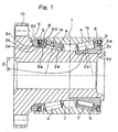
- a tapered roller bearing assembly for supporting a vehicle wheel shown therein is a dual row tapered bearing model of a hub unit type.
- This wheel support bearing assembly includes an outer member 1 having an inner periphery formed with dual rows of tapered rolling faces 1a, in which reduced diameter ends adjoin with each other, an inner member 2 having an outer periphery formed with tapered rolling faces 2a confronting the rolling faces 1a, and dual rows of tapered rollers 4 interposed between the rolling faces 1a in the outer member 1 and the rolling faces 2a in the inner member 2.
- the tapered rollers 4 are retained by a roller retainer 7 employed for each of the rows of the tapered rollers 4.
- the outer member 1 is provided at its opposite ends with sealing members 8, respectively, for sealing an annular space delimited between the inner and outer members 2 and 1.
- the inner member 2 is made up of a hub axle 3 having a hub flange 10 formed at an outboard end thereof, and a single row inner race 5 mounted on an inboard end of the hub axle 3, with the rolling faces 2a defined in the hub axle 3 and the single row inner race 5, respectively.
- a collar ring 6 is mounted on a portion of the outer periphery of the hub axle 3 adjacent the hub flange 10 for engagement with large diameter ends of each of the tapered rollers 4 of the outboard row.
- a tire wheel is fixedly mounted on the hub flange 10 by means of bolts (not shown) extending through holes defined in the hub flange 10 in a direction circumferentially of the latter.
- the hub axle 3 is coupled with one end of a constant velocity universal joint, for example, a joint outer race, while the other end (i.e., a joint inner race) of the constant velocity universal joint is connected to a drive axle.
- the inboard end of the hub axle 3 has an inner race mounting area 3c defined on the outer peripheral surface thereof, and the single row inner race 5 is mounted on the inner race mounting area 3c.
- the single row inner race 5 includes a large collar 5a defined in an inboard end thereof, the large collar 5a having a side face with which the large diameter ends of the tapered rollers 4 of the inboard row are engageable.
- a seal contact ring 9, with which the sealing member 8 secured to an inner peripheral surface of the outer member 1 is slidingly engageable, is fixedly mounted on an outer periphery of the large collar 5a. This sealing member 8 may alternatively engage directly with the outer peripheral surface of the large collar 5a on the single row inner race 5.
- a portion of the inboardmost end of the single row inner race 5 is rendered to be a crimped portion 3d so crimped radially outwardly to urge an annular end face of the single row inner race 5 and, by means of this crimped portion 3, the singe row inner race 5 is axially fixedly fastened.
- a portion of the outer peripheral surface of the hub axle 3 on an inboard side of the hub flange 10 has a collar ring mounting area 3a of a cylindrical configuration defined therein, and from this collar ring mounting area 3a, an arcuately sectioned surface area 3b continued to a side face of the hub flange 10 is formed.
- a collar ring 6 is mounted on this collar ring mounting area 3a and includes a cylindrical inner peripheral surface area 6a held in contact with the collar ring mounting area 3a of the hub axle 3, an end face 6b held in abutment with the side face of the hub flange 10, and a non-contact inner peripheral surface area 6c defined in the collar ring 6 at a location between the end face 6b to the cylindrical inner peripheral surface area 6a and held in non-contact relation with the arcuately sectioned surface area 3b.
- An outer peripheral surface of the collar ring 6 is formed as a stepped cylindrical outer peripheral surface having a large diameter on one side adjacent the hub flange 10.
- the sealing member 8 may alternatively be caused to slidably engage directly with the reduced diameter portion 6d of the outer peripheral surface of the collar ring 6.
- the collar provided in the neighbor of the rolling face 2a adjacent the hub flange 10 of the hub axle 3 is formed as a collar ring 6 separate from the hub axle 3 and this separate collar ring 6 is mounted externally on the hub axle 3 and, therefore, stress concentration, tending to occur at a boundary between the rolling face 2a of the hub axle 3 and a surface of the collar as a result of contact with the tapered rollers 4, can be lessened. Accordingly, even though the bearing assembly of the present invention is used in association with a kind of vehicles having a heavy weight, the fatigue hardly occurs in the boundary referred to above, rendering the bearing assembly of the present invention robust.
- the outer peripheral surface of the hub axle 3 is provided with the arcuately sectioned surface area 3b having a large radius of curvature and continuing from the collar ring mounting area 3a to the side face of the hub flange 10 and the collar ring 6 has the non-contact inner peripheral surface area 6c that establishes a non-contact relation with the arcuately sectioned surface area 3b, stress concentration brought about by the load loaded on this portion from the row of the tapered rollers 4 on an outboard side and through the collar ring 6 can further be lessened.
- the outer peripheral surface of the collar ring 6 is formed as the stepped cylindrical surface and the sealing member 8 secured to the outer member 1 is made to slidingly engage with the reduced diameter portion 6d of this stepped outer peripheral surface, even though the collar ring 6 separate from the hub axle 3 is employed, the outboard sealing member 8 between the outer member 1 and the inner member 2 can be arranged with high space efficiency or high efficiency of utilization of the space. For this reason, it is possible to use the collar ring 6 of a sufficient size for given bearing dimensions to achieve excellent durability and, also, the sealability can be secured.
- Fig. 2 illustrates a second preferred embodiment of the present invention.
- This embodiment is similar to the tapered roller, wheel support bearing assembly shown in Fig. 1, except that in this embodiment the collar ring 6 which has been described as mounted on the hub axle 3 is dispensed with and, instead, a collar 11 engageable with the large diameter ends of the outboard row of the tapered roller 4 is formed on the inner periphery of the outer member 11.
- a portion of the outer periphery of the hub axle 3, which lies between the rolling face 2a for the outboard row of the tapered rollers 4 and the side face of the hub flange 10 is formed as a smooth arcuately sectioned surface area 3bb.
- the sealing member 8 secured to the inner peripheral surface of the outboard end of the outer member 1 is held in sliding engagement with the arcuately sectioned surface area 3bb.
Landscapes
- Engineering & Computer Science (AREA)
- General Engineering & Computer Science (AREA)
- Mechanical Engineering (AREA)
- Rolling Contact Bearings (AREA)
Applications Claiming Priority (2)
| Application Number | Priority Date | Filing Date | Title |
|---|---|---|---|
| JP2003137078A JP2004340242A (ja) | 2003-05-15 | 2003-05-15 | 円錐ころ型車輪用軸受装置 |
| PCT/JP2004/006241 WO2004101295A1 (fr) | 2003-05-15 | 2004-05-10 | Dispositif a roulement a rouleaux coniques pour roue |
Publications (1)
| Publication Number | Publication Date |
|---|---|
| EP1623846A1 true EP1623846A1 (fr) | 2006-02-08 |
Family
ID=33447246
Family Applications (1)
| Application Number | Title | Priority Date | Filing Date |
|---|---|---|---|
| EP04732007A Withdrawn EP1623846A1 (fr) | 2003-05-15 | 2004-05-10 | Dispositif a roulement a rouleaux coniques pour roue |
Country Status (5)
| Country | Link |
|---|---|
| US (1) | US7507029B2 (fr) |
| EP (1) | EP1623846A1 (fr) |
| JP (1) | JP2004340242A (fr) |
| CN (1) | CN100453343C (fr) |
| WO (1) | WO2004101295A1 (fr) |
Cited By (2)
| Publication number | Priority date | Publication date | Assignee | Title |
|---|---|---|---|---|
| EP1721757A1 (fr) | 2005-05-10 | 2006-11-15 | Ntn Corporation | Agencement de palier pour roue de véhicule |
| US7832942B2 (en) | 2006-09-01 | 2010-11-16 | Ntn Corporation | Wheel bearing apparatus |
Families Citing this family (22)
| Publication number | Priority date | Publication date | Assignee | Title |
|---|---|---|---|---|
| WO2007052807A1 (fr) | 2005-11-07 | 2007-05-10 | Ntn Corporation | Dispositif de roulement de roue |
| JP4064433B2 (ja) * | 2005-12-16 | 2008-03-19 | Ntn株式会社 | 車輪用軸受装置 |
| JP2007218292A (ja) * | 2006-02-14 | 2007-08-30 | Ntn Corp | 車輪用軸受装置 |
| WO2007132563A1 (fr) * | 2006-05-15 | 2007-11-22 | Ntn Corporation | Dispositif de roulement pour roue |
| JP4994713B2 (ja) * | 2006-05-26 | 2012-08-08 | Ntn株式会社 | 車輪用軸受装置 |
| JP4998980B2 (ja) * | 2006-06-15 | 2012-08-15 | Ntn株式会社 | 車輪用軸受装置 |
| WO2007138740A1 (fr) * | 2006-05-26 | 2007-12-06 | Ntn Corporation | Dispositif de palier pour roue |
| JP4998978B2 (ja) * | 2006-06-15 | 2012-08-15 | Ntn株式会社 | 車輪用軸受装置 |
| JP4998979B2 (ja) * | 2006-06-15 | 2012-08-15 | Ntn株式会社 | 車輪用軸受装置 |
| JP4998983B2 (ja) * | 2006-09-01 | 2012-08-15 | Ntn株式会社 | 車輪用軸受装置 |
| JP4371429B2 (ja) * | 2007-05-29 | 2009-11-25 | Ntn株式会社 | 車輪用軸受装置 |
| DE102007060407A1 (de) * | 2007-12-14 | 2009-06-18 | Schaeffler Kg | Lageranordnung und Kraftfahrzeug mit einer Lageranordnung |
| JP5184875B2 (ja) * | 2007-12-19 | 2013-04-17 | Ntn株式会社 | 車輪用軸受装置 |
| JP2013092246A (ja) * | 2011-10-27 | 2013-05-16 | Jtekt Corp | 車輪用軸受装置 |
| CN102537035A (zh) * | 2011-12-29 | 2012-07-04 | 公主岭轴承有限责任公司 | 带有宽挡边的圆锥滚子轴承 |
| CN103899642B (zh) * | 2012-12-27 | 2017-02-15 | 北京谊安医疗系统股份有限公司 | 集成回转装置的医用吊塔旋臂回转机构 |
| DE102013212989B4 (de) * | 2013-07-03 | 2015-10-08 | Aktiebolaget Skf | Maschinenanordnung |
| JP6748400B2 (ja) * | 2014-07-01 | 2020-09-02 | 内山工業株式会社 | 密封装置 |
| US9493035B2 (en) * | 2014-07-11 | 2016-11-15 | Aktiebolaget Skf | Flanged hub-bearing unit |
| EP3012475B1 (fr) * | 2014-10-23 | 2017-05-17 | Aktiebolaget SKF | Unité de roulement de moyeu avec un dispositif d'étanchéité |
| US10329011B2 (en) | 2015-10-02 | 2019-06-25 | Goodrich Corporation | Axle saddle |
| CN114103550A (zh) * | 2021-11-28 | 2022-03-01 | 中国船舶重工集团公司第七一三研究所 | 一种适用于全向车的转向驱动轮系 |
Family Cites Families (16)
| Publication number | Priority date | Publication date | Assignee | Title |
|---|---|---|---|---|
| US2274218A (en) * | 1940-02-02 | 1942-02-24 | Timken Roller Bearing Co | Roller bearing axle construction |
| US2977138A (en) * | 1957-04-12 | 1961-03-28 | Gen Motors Corp | Flexible seal |
| US4136916A (en) | 1977-06-27 | 1979-01-30 | The Timken Company | Unitized single row tapered roller bearing |
| JPS56119015U (fr) * | 1980-02-14 | 1981-09-10 | ||
| JPS5853126B2 (ja) | 1980-02-19 | 1983-11-28 | 住友電気工業株式会社 | 可撓性膜製起伏堰 |
| JPS6237619A (ja) | 1985-08-07 | 1987-02-18 | Dainichi Kogyo Kk | 液体燃料燃焼装置 |
| JPH0234498Y2 (fr) * | 1985-08-23 | 1990-09-17 | ||
| CN2106758U (zh) * | 1991-10-15 | 1992-06-10 | 本溪钢铁公司运输部 | 渣罐车双列圆锥滚子轴承轴箱装置 |
| US5259676A (en) | 1992-03-30 | 1993-11-09 | Marti Milford F | Roller bearing spindle and hub assembly |
| DE69929480T3 (de) | 1998-08-18 | 2009-11-19 | Nsk Ltd. | Kraftfahrzeugnabeneinheit |
| JP2000065049A (ja) * | 1998-08-24 | 2000-03-03 | Nippon Seiko Kk | 自動車用ハブユニット及びその組立方法 |
| JP2000211310A (ja) | 1999-01-21 | 2000-08-02 | Ntn Corp | 車輪の支持構造 |
| CN2451630Y (zh) * | 2000-08-24 | 2001-10-03 | 三一重工股份有限公司 | 压路机振动轮支承座组件 |
| US20020064327A1 (en) | 2000-10-27 | 2002-05-30 | Koyo Seiko Co., Ltd. | Vehicle-use bearing apparatus |
| JP2002206538A (ja) | 2000-10-27 | 2002-07-26 | Koyo Seiko Co Ltd | 車両用軸受装置 |
| JP4501324B2 (ja) * | 2001-08-09 | 2010-07-14 | 日本精工株式会社 | 複列円すいころ軸受ユニットの組立方法 |
-
2003
- 2003-05-15 JP JP2003137078A patent/JP2004340242A/ja active Pending
-
2004
- 2004-05-10 US US10/556,468 patent/US7507029B2/en not_active Expired - Fee Related
- 2004-05-10 WO PCT/JP2004/006241 patent/WO2004101295A1/fr active Application Filing
- 2004-05-10 EP EP04732007A patent/EP1623846A1/fr not_active Withdrawn
- 2004-05-10 CN CNB2004800127172A patent/CN100453343C/zh not_active Expired - Fee Related
Non-Patent Citations (1)
| Title |
|---|
| See references of WO2004101295A1 * |
Cited By (2)
| Publication number | Priority date | Publication date | Assignee | Title |
|---|---|---|---|---|
| EP1721757A1 (fr) | 2005-05-10 | 2006-11-15 | Ntn Corporation | Agencement de palier pour roue de véhicule |
| US7832942B2 (en) | 2006-09-01 | 2010-11-16 | Ntn Corporation | Wheel bearing apparatus |
Also Published As
| Publication number | Publication date |
|---|---|
| WO2004101295A1 (fr) | 2004-11-25 |
| US20070031079A1 (en) | 2007-02-08 |
| JP2004340242A (ja) | 2004-12-02 |
| US7507029B2 (en) | 2009-03-24 |
| CN100453343C (zh) | 2009-01-21 |
| CN1787925A (zh) | 2006-06-14 |
Similar Documents
| Publication | Publication Date | Title |
|---|---|---|
| US7507029B2 (en) | Tapered roller bearing assembly for supporting vehicle wheel | |
| US8356942B2 (en) | Sealing device for bearing assembly and wheel support bearing assembly therewith | |
| US7866893B2 (en) | Bearing apparatus for a wheel of vehicle | |
| EP0860626A2 (fr) | Raccordement entre une unité moyeu de roue-palier et un rotor de frein | |
| EP1939471B1 (fr) | Dispositif de roulement pour roue | |
| JP2010230150A (ja) | 環状密封装置 | |
| KR20030036763A (ko) | 취급을 위하여 단위체화된 베어링 | |
| JP2000509791A (ja) | 軸受構造のための封止装置及び軸受装置の封止のための構造 | |
| JP2005061616A (ja) | 車輪用軸受装置 | |
| EP1308316A1 (fr) | Dispositif de support pour essieu | |
| US20090010583A1 (en) | Multi-Row Anti-Friction Bearing | |
| US7758249B2 (en) | Wheel support rolling bearing unit with seal ring | |
| EP0310389B1 (fr) | Roulement pour une roue de véhicule automobile | |
| CN211778585U (zh) | 轮毂单元轴承 | |
| US6033123A (en) | Tapered roller bearing | |
| EP1479931A2 (fr) | Dispositif de support de roue avec ensemble de palier | |
| JP4690170B2 (ja) | 複列転がり軸受 | |
| US20080298732A1 (en) | Unitized Single Row Bearing with Reverse Thrust Capabilities | |
| JP5067810B2 (ja) | シールリング | |
| JP6515774B2 (ja) | 車輪支持用複列円すいころ軸受ユニット | |
| JP4000751B2 (ja) | 車両用ハブユニット | |
| JP2006312961A (ja) | 車輪用軸受装置 | |
| JPH10181304A (ja) | 車輪用ハブユニット軸受 | |
| JP4899921B2 (ja) | 軸受組立方法 | |
| US20080205808A1 (en) | Wheel bearing |
Legal Events
| Date | Code | Title | Description |
|---|---|---|---|
| PUAI | Public reference made under article 153(3) epc to a published international application that has entered the european phase |
Free format text: ORIGINAL CODE: 0009012 |
|
| 17P | Request for examination filed |
Effective date: 20051122 |
|
| AK | Designated contracting states |
Kind code of ref document: A1 Designated state(s): DE FR |
|
| DAX | Request for extension of the european patent (deleted) | ||
| RBV | Designated contracting states (corrected) |
Designated state(s): DE FR |
|
| STAA | Information on the status of an ep patent application or granted ep patent |
Free format text: STATUS: THE APPLICATION IS DEEMED TO BE WITHDRAWN |
|
| 18D | Application deemed to be withdrawn |
Effective date: 20100324 |