EP1623364B1 - Kartenaufnahmevorrichtung - Google Patents
Kartenaufnahmevorrichtung Download PDFInfo
- Publication number
- EP1623364B1 EP1623364B1 EP04722833A EP04722833A EP1623364B1 EP 1623364 B1 EP1623364 B1 EP 1623364B1 EP 04722833 A EP04722833 A EP 04722833A EP 04722833 A EP04722833 A EP 04722833A EP 1623364 B1 EP1623364 B1 EP 1623364B1
- Authority
- EP
- European Patent Office
- Prior art keywords
- card
- closure element
- receiving device
- card receiving
- closure
- Prior art date
- Legal status (The legal status is an assumption and is not a legal conclusion. Google has not performed a legal analysis and makes no representation as to the accuracy of the status listed.)
- Expired - Lifetime
Links
Images



Classifications
-
- G—PHYSICS
- G06—COMPUTING OR CALCULATING; COUNTING
- G06K—GRAPHICAL DATA READING; PRESENTATION OF DATA; RECORD CARRIERS; HANDLING RECORD CARRIERS
- G06K13/00—Conveying record carriers from one station to another, e.g. from stack to punching mechanism
- G06K13/02—Conveying record carriers from one station to another, e.g. from stack to punching mechanism the record carrier having longitudinal dimension comparable with transverse dimension, e.g. punched card
- G06K13/08—Feeding or discharging cards
- G06K13/0868—Feeding or discharging cards using an arrangement for keeping the feeding or insertion slot of the card station clean of dirt, or to avoid feeding of foreign or unwanted objects into the slot
- G06K13/0875—Feeding or discharging cards using an arrangement for keeping the feeding or insertion slot of the card station clean of dirt, or to avoid feeding of foreign or unwanted objects into the slot the arrangement comprising a shutter for blocking at least part of the card insertion slot
-
- G—PHYSICS
- G06—COMPUTING OR CALCULATING; COUNTING
- G06K—GRAPHICAL DATA READING; PRESENTATION OF DATA; RECORD CARRIERS; HANDLING RECORD CARRIERS
- G06K13/00—Conveying record carriers from one station to another, e.g. from stack to punching mechanism
- G06K13/02—Conveying record carriers from one station to another, e.g. from stack to punching mechanism the record carrier having longitudinal dimension comparable with transverse dimension, e.g. punched card
- G06K13/08—Feeding or discharging cards
-
- G—PHYSICS
- G07—CHECKING-DEVICES
- G07C—TIME OR ATTENDANCE REGISTERS; REGISTERING OR INDICATING THE WORKING OF MACHINES; GENERATING RANDOM NUMBERS; VOTING OR LOTTERY APPARATUS; ARRANGEMENTS, SYSTEMS OR APPARATUS FOR CHECKING NOT PROVIDED FOR ELSEWHERE
- G07C7/00—Details or accessories common to the registering or indicating apparatus of groups G07C3/00 and G07C5/00
Definitions
- the invention relates to a card receiving device, in particular for a tachograph in a motor vehicle in flat construction, which fully retracts a card in a plane of movement, with an elongated receiving opening through which the card enters the card receiving device and with a closure having a closure element, which extends in the longitudinal direction of the receiving opening and in the closed position of the closure, the receiving opening blocks, wherein the closure element is movable in the normal direction of the movement plane in the context of the stroke required for receiving the card.
- the focus of the application of the device according to the invention is in the field of tachographs or devices for recording the working hours and rest periods of commercial vehicle drivers.
- other applications are also conceivable, for.
- Advantageous application of the invention finds in combination with all types of card-shaped data carriers. Due to the high economic and legal significance of the data to be recorded in tachographs, the records must be reliably secured against manipulation.
- the security measures concern both data acquisition and data transmission as well as the transmission and storage of the collected data in the memory of the card. Relevant standards place stringent requirements on the safety standard to be achieved by the measures.
- the card is completely prescribed by the card receiving device is absorbed and isolated from the environment by means of suitable closure devices.
- the closure devices must be locked in the closed position during read and write operations. Additional difficulties arise due to contamination-related functional failures of conventional devices, in particular by contact interruptions or even when the card is inserted.
- the indentation and exact positioning of the card on the contacts of the device are problematic because the various cards have high manufacturing tolerances in relation to the required positional accuracy to the contacts of the device. Since the cards are distinguished in the perception of the user mainly by a high degree of robustness, they are usually not treated with the care actually required, so that in addition to the tolerances caused by manufacturing deformations and damage the operation in interaction with the card receiving devices affect.
- the operating conditions in motor vehicles put increased demands on the functional safety due to the strong vibrations and countless shocks as well as the far-reaching temperature fluctuations.
- European Patent Application EP 1 017 013 A3 already discloses a closing device for a device close to the generic type, in which a segmented drum obstructs or releases the opening, wherein the drum is controlled and driven by means of a suitable gear. Due to the high design and manufacturing complexity, this solution is not suitable for mass production. European Patent EP 0 342 407 B1 already discloses a device in which a closure can be moved in a generic manner, but the proposed solution is also extremely expensive.
- DE 35 18 247 A1 describes a locking and unlocking device for a card reader, in which the card is locked during the reading operation by means of a hook.
- the hook protrudes into the receiving slot and partially obstructs it.
- the hook In order to release the lock for issuing the card, the hook must be turned by means of a complex lever device.
- FR 2 801 393 A discloses a portable card reader which is particularly integrated in a mobile telephone.
- the card reader is designed so that no dust can penetrate in the absence of a card.
- an open insertion slot for the card instead of a flap is provided which bears against a stop edge.
- the card is between However, the flap and stop edge are inserted, but partly remain outside the card reader.
- the invention has the object to close a card receiving device sufficiently by means of a closure relevant protection classes while maintaining a high level of mass production, low production costs and reliable operation.
- the object is achieved by a card receiving device according to claim 1.
- the key advantage of the invention lies in the incomparably low cost of the resilient mounting, which makes additional mechanical, especially geared components largely superfluous.
- the captivatingly simple solution is accompanied by high reliability and low production costs due to its low design complexity.
- the installation space for the closure is reduced considerably, which is of the highest interest particularly in the case of the installation space which is predetermined in the area of motor vehicle tachographs and which is similar to the format of a car radio. Without special manufacturing effort can be an excellent operation of the closure at a height of less than 10 mm realized.
- the leaf spring may advantageously extend in a development substantially in a plane parallel to the map plane. In this way, the closure element moves in the elongated leaf spring substantially translationally and perpendicular to the plane of motion, so that an advantageous guillotine-like closing takes place.
- the key advantage is the saving of all geared components, since the proposed leaf spring gives the arrangement exactly the required degrees of freedom of movement. At the same time, the inventively advantageous resilient mounting is provided.
- the closure element is resiliently mounted in the normal direction of the movement plane in the context of the stroke required for receiving the chip card.
- the advantages of the invention result from the combination of the resilient mounting in the normal direction of the plane of movement with a substantially translationally oriented in the normal direction of the plane of movement of the closure element.
- rotational movements around small angles do not diminish the success according to the invention, as long as the movement of the closure element is essentially a translatory movement oriented perpendicular to the plane of movement.
- the ratio of the stroke required for receiving the card to the distance of a rotational axis of the movement of the closure element located in the inward direction of the closure element is important.
- this axis of rotation is arranged in the inward direction at least ten times the usual stroke of the closure element away from the closure element. The same applies to the attachment of one end of the leaf spring connected to the closure element.
- the closure element on the input side a located in the longitudinal direction of the receiving opening outside Has inlet slope for the card to be inserted.
- the closure element has a running in the longitudinal direction of the receiving opening located inside bevel for the chandelierschiebende card.
- the closure element is elastically biased in the closed position on a counter system, the card during the inward movement in the card receiving device between the counter system and the Closing element is arranged, facing the closure element with a first flat side and faces with a second flat side of the counter-system and the closure element is braced against the closure element facing the flat side of the card. In this way, contaminants are stripped during the pull-in movement by means of the closure element of the card.
- the stripping process can be carried out both by the closure element and by the counter system.
- the card receiving device has a contact set for contacting the card, which is arranged on the same side of the plane of movement as the closure element. In this way, the card is particularly thoroughly freed on that flat side of dirt, which occurs in the end position with the contacts of the contact set in a conductive connection.
- an arrangement of the same on the opposite side of the contact set of the card makes sense in the same way due to the contact force of the closure element.
- the device For a pleasing appearance, it is useful to provide the device with a front panel having a back and a visible side and is provided in the region of the receiving opening of the card receiving device with a recess which is at least partially surrounded by a third seal on the back, which seals against the front of the card receiving device in the region of the receiving opening, so that neither splash water nor dust can penetrate.
- this third seal forms a component with the seal already sealing against the closure element, so that the card receiving device has a front panel with a rear side, a visible side and a recess in the region of the receiving opening, the cross section of the seal has a harder extending in the longitudinal direction Has region in which the closure element in the closed position and a softer area, which at the back of the panel is applied.
- the panel below the recess has at least one drainage opening.
- closure element has a wedge-shaped tapering or tapered to the seal cross section, so that it in the closed position to a substantially line-like contact between the seal and the closure element comes.
- the card receiving device has a locking unit that locks the closure in the closed position.
- the locking element of the locking unit in the closed position blocks the leaf spring.
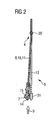
- an inventive closure element 7 of a closure 6 is provided with the reference numeral 7 and shown together with a cantilever 10 formed as an elastic element 8 and a leaf spring 11 on a support 13.
- the carrier 13 and the leaf spring 11 are punched out of a sheet metal and the closure element 7 is molded onto the input-side end of the leaf spring 11 as a plastic part.
- Snap-in hooks 31 for mounting a sealing unit 32 shown in FIGS. 6 to 12 are likewise injection-molded onto the carrier 13.
- the movement of the closure element 7 of the closure 6 can be rotated as a rotation about one in the region of the attachment of the leaf spring 11 due to the small amplitude arranged, parallel to a plane of movement 4 of a card 2 extending first axis of rotation 20 describe.
- the closure element 7 has an outer inlet bevel 14 on the input side in an inward direction 9.
- a card is able to push aside the closure element 7 from a receiving opening 5 perpendicular to the plane of movement 4 of the card 2.
- On the inner side of the closure element 7 is also an inner inlet bevel 15, which allows the card 2 to push the closure element 7 on exit from the device aside.
- the leaf spring 11 carrying the closure element 7 is bent approximately 6 mm offset from the plane of the carrier 13 in the direction of the plane of movement 4 of the card 2 and so provided with a resulting in contact with an abutment in operation bias.
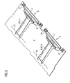
- tachographs usually two closures according to the invention are arranged on a common carrier 13, as shown in Fig. 3.
- FIGS. 4, 5 show a locking unit 29 provided with the reference numeral 29. 4, the locking unit 29 is in an unlocked position and in Fig. 5, the closure element is locked by means of the locking unit 29.
- the locking unit 29 has two locking elements 30, 35, each pivotable about a third axis of rotation 33, 34.
- the two locking elements 30, 35 are arranged on both sides of the plane of movement 4 for a card on the side of the shutter 6.
- the locking elements 35, 30 are each provided with an inlet slope 36, 37 at the end faces facing the closure element 7, which allows the locking elements 30, 35 to lie behind the plane in a plane between the plane of the closure element 7 and the plane of the carrier 13 Push closure element 7 so that the closure 6 can no longer spring back into an open position.
- a sealing unit 32 which seal recessed recesses 38, 39, which correspond to the latching hooks 31.
- the plastic sealing unit 32 comprises the receiving opening 5 for the card in the movement plane 4 U-shaped and is provided on the movement plane 4 side facing with a seal 40.
- the seal 40 sums up in the longitudinal direction of the Receiving opening 5 extending first seal 21 and two in the transverse direction of the receiving opening 5 extending second seals 22 integrally together.
- the seal 40 is inserted in a form-fitting manner in a corresponding receiving formation 41 in the sealing unit.
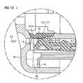
- the cross section of the seal 40 shown in Fig. 8 shows the arrangement with a first sealing lip 42 for sealing against a front panel 25.
- the region of the second seal 22 has a chamber-like recess with a resiliently formed in the inward direction 9 facing second sealing lip 43.
- the second sealing lip 43 seals against a laterally protruding sealing surface 44 of the closure element, so that no spray water can penetrate laterally of the closure element 7.
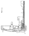
- the closure element 7 of the closure 6 closes with a movement from bottom to top, ie substantially counter to the direction of the force of gravity and arrives in the closed position when installed correctly the first seal 21 to the plant.
- the mounting position can be inclined according to the invention by up to 30 °.
- the resilient closure 7 prevents this falling out of the card when ejected by clamping. Due to the wedge shape of the closure element 7, the system is substantially linear. Due to this arrangement, the seal 40 around the receiving opening 5 describes a substantially inverted U-shape.
- the sealing against the front panel 25 portion is formed as a softer area 24 of the seal 40 and is softer than an adjacent arranged as an abutment of the closure element harder area 23.
Landscapes
- General Physics & Mathematics (AREA)
- Physics & Mathematics (AREA)
- Engineering & Computer Science (AREA)
- Theoretical Computer Science (AREA)
- Lock And Its Accessories (AREA)
- Devices For Checking Fares Or Tickets At Control Points (AREA)
- Time Recorders, Dirve Recorders, Access Control (AREA)
- Coupling Device And Connection With Printed Circuit (AREA)
- Casings For Electric Apparatus (AREA)
- Conveying Record Carriers (AREA)
- Details Of Rigid Or Semi-Rigid Containers (AREA)
- Input Circuits Of Receivers And Coupling Of Receivers And Audio Equipment (AREA)
- Vending Machines For Individual Products (AREA)
- Sheet Holders (AREA)
- Liquid Crystal (AREA)
- Grinding Of Cylindrical And Plane Surfaces (AREA)
- Control And Other Processes For Unpacking Of Materials (AREA)
Priority Applications (1)
| Application Number | Priority Date | Filing Date | Title |
|---|---|---|---|
| PL04722833T PL1623364T3 (pl) | 2003-05-12 | 2004-03-24 | Urządzenie do umieszczania kart |
Applications Claiming Priority (2)
| Application Number | Priority Date | Filing Date | Title |
|---|---|---|---|
| DE10321242A DE10321242B4 (de) | 2003-05-12 | 2003-05-12 | Kartenaufnahmevorrichtung |
| PCT/EP2004/003137 WO2004100047A2 (de) | 2003-05-12 | 2004-03-24 | Kartenaufnahmevorrichtung |
Publications (2)
| Publication Number | Publication Date |
|---|---|
| EP1623364A2 EP1623364A2 (de) | 2006-02-08 |
| EP1623364B1 true EP1623364B1 (de) | 2006-08-30 |
Family
ID=33426748
Family Applications (1)
| Application Number | Title | Priority Date | Filing Date |
|---|---|---|---|
| EP04722833A Expired - Lifetime EP1623364B1 (de) | 2003-05-12 | 2004-03-24 | Kartenaufnahmevorrichtung |
Country Status (12)
| Country | Link |
|---|---|
| US (1) | US7389936B2 (da) |
| EP (1) | EP1623364B1 (da) |
| JP (1) | JP2006526197A (da) |
| CN (1) | CN100380398C (da) |
| AT (1) | ATE338312T1 (da) |
| BR (1) | BRPI0410285A (da) |
| DE (2) | DE10321242B4 (da) |
| DK (1) | DK1623364T3 (da) |
| ES (1) | ES2268648T3 (da) |
| PL (1) | PL1623364T3 (da) |
| RU (1) | RU2325696C2 (da) |
| WO (1) | WO2004100047A2 (da) |
Families Citing this family (10)
| Publication number | Priority date | Publication date | Assignee | Title |
|---|---|---|---|---|
| US7306159B1 (en) * | 2003-06-07 | 2007-12-11 | Rochelo Donald R | Protective case for six different sized memory cards |
| DE102006030658A1 (de) | 2006-07-03 | 2008-01-10 | Siemens Ag | Datenkarteneinführeinrichtung |
| DE102006031880A1 (de) * | 2006-07-10 | 2008-01-17 | Siemens Ag | Kartenaufnahmevorrichtung |
| DE102007015335B4 (de) | 2007-03-30 | 2010-03-25 | Amphenol-Tuchel Electronics Gmbh | Kartenlese- und/oder Schreibeinheit |
| DE102007062318B4 (de) * | 2007-12-21 | 2010-02-18 | Amphenol-Tuchel Electronics Gmbh | Schmutz- und Manipulationsgeschützter Kartenleser |
| US7874857B2 (en) * | 2009-01-23 | 2011-01-25 | Ddk Ltd. | Card connector |
| DE102015122472B4 (de) | 2015-12-21 | 2019-03-14 | Amphenol-Tuchel Electronics Gmbh | Kontaktschutzanordnung für einen Kartenleser |
| DE102016214180A1 (de) * | 2016-08-01 | 2018-02-01 | Continental Automotive Gmbh | Chipkartenlesegerät |
| JP7048239B2 (ja) * | 2017-09-29 | 2022-04-05 | 日本電産サンキョー株式会社 | カードリーダ |
| FR3098954B1 (fr) * | 2019-07-16 | 2022-12-30 | Ingenico Group | Système de lecture de carte de transaction avec volet de protection |
Family Cites Families (36)
| Publication number | Priority date | Publication date | Assignee | Title |
|---|---|---|---|---|
| DE3505068C1 (de) * | 1985-02-14 | 1986-06-19 | Mannesmann Kienzle GmbH, 7730 Villingen-Schwenningen | Fahrtschreiber fuer Kraftfahrzeuge |
| DE3518247A1 (de) * | 1985-05-21 | 1986-11-27 | Siemens AG, 1000 Berlin und 8000 München | Ver- und entriegelungseinrichtung fuer einen kartenleser |
| US4800551A (en) | 1987-05-15 | 1989-01-24 | Polaroid Corporation | Method and apparatus for feeding card |
| DE8805789U1 (de) | 1988-05-02 | 1988-07-14 | Mannesmann Kienzle GmbH, 7730 Villingen-Schwenningen | Schlitzsperre zum Verschließen einer Ein-/Ausgabeöffnung eines Datenerfassungsgerätes |
| EP0363992B1 (en) | 1988-10-14 | 1996-04-03 | Omron Corporation | Card reader having locking mechanism |
| DE3902088C1 (da) * | 1989-01-25 | 1990-01-04 | Mannesmann Kienzle Gmbh, 7730 Villingen-Schwenningen, De | |
| DE4139482A1 (de) * | 1991-11-29 | 1993-06-03 | Man Technologie Gmbh | Schutzeinrichtung fuer eletronische kartenlesegeraete |
| DE9213283U1 (de) * | 1992-10-02 | 1992-11-26 | Siemens AG, 8000 München | Kartenleser |
| DE4315746A1 (de) | 1993-05-11 | 1994-11-17 | Amphenol Tuchel Elect | Fremdkörpersperre für Kartenleser |
| DE4402229A1 (de) | 1994-01-26 | 1995-07-27 | Siemens Ag | Kartenleser |
| US5518412A (en) | 1994-07-07 | 1996-05-21 | Larabell; Henri J. | Geared bracket and slide assembly |
| JP2898887B2 (ja) * | 1994-08-31 | 1999-06-02 | 沖電気工業株式会社 | Icカードの読み取り装置 |
| JPH08293008A (ja) * | 1995-04-20 | 1996-11-05 | Clarion Co Ltd | カード状媒体の着脱装置 |
| US5714742A (en) * | 1995-05-10 | 1998-02-03 | Matsushita Electric Industrial Co., Ltd. | IC-card reader/writer for an IC-card |
| DE19547060C2 (de) * | 1995-12-18 | 1998-05-14 | Bernhard Vogler | Einrichtung zum Verschließen und/oder Sperren des Karteneinführungsschlitzes an Codekartenlesern |
| FR2764100B1 (fr) | 1997-05-30 | 1999-08-06 | Framatome Connectors Int | Connecteur pour lecteur de carte comportant des contacts a double detection |
| DE19757626B4 (de) | 1997-12-23 | 2005-08-25 | Amphenol-Tuchel Electronics Gmbh | Chipkartenleser für unterschiedliche Verwendungszwecke |
| JP3367039B2 (ja) * | 1998-01-09 | 2003-01-14 | アンリツ株式会社 | Icカード処理装置 |
| DE19809619A1 (de) | 1998-03-06 | 1999-09-09 | Mannesmann Vdo Ag | Vorrichtung zum Transport von Datenkarten |
| DE19815549C2 (de) | 1998-04-07 | 2000-04-27 | Itt Mfg Enterprises Inc | Steckkarte für elektronische Geräte |
| DE19857226A1 (de) | 1998-12-11 | 2000-06-15 | Mannesmann Vdo Ag | Schließvorrichtung für eine Lese-/Schreibaggregat für Datenkarten |
| EP1060456B1 (de) * | 1998-12-31 | 2002-10-23 | AMPHENOL-TUCHEL ELECTRONICS GmbH | Kartensperre für smart card connector |
| JP3362691B2 (ja) * | 1999-03-08 | 2003-01-07 | 松下電器産業株式会社 | Icカードリーダ |
| US6824062B2 (en) * | 1999-05-17 | 2004-11-30 | Kabushiki Kaisha Sankyo Seisakusho | Card transporting mechanism for card reader |
| DE19947162C1 (de) | 1999-10-01 | 2000-09-28 | Itt Mfg Enterprises Inc | Steckkarte für elektronische Geräte |
| FR2801393B1 (fr) | 1999-11-19 | 2003-12-26 | Sagem | Lecteur de carte a puce portable et utilisation de ce lecteur dans un telephone mobile |
| EP1170692B1 (en) | 2000-07-07 | 2009-03-25 | AMPHENOL-TUCHEL ELECTRONICS GmbH | A smart-card reader |
| JP3961224B2 (ja) | 2001-02-26 | 2007-08-22 | アルプス電気株式会社 | カード用コネクタ装置 |
| DE10112061B4 (de) | 2001-03-14 | 2007-08-30 | Siemens Ag | Aufnahmevorrichtung für in Fahrzeugen verwendete, der personenbezogenen Erfassung von Fahrtdaten dienende Chipkarten |
| JP3828003B2 (ja) * | 2001-12-04 | 2006-09-27 | 日本電産サンキョー株式会社 | Icカードリーダ |
| TW556899U (en) * | 2002-05-14 | 2003-10-01 | I O Interconnect Inc | Improvement of PC card structure |
| TW554592B (en) * | 2002-08-13 | 2003-09-21 | Carry Computer Eng Co Ltd | Connector module for tray-like electric memory card |
| JP4039518B2 (ja) | 2002-09-09 | 2008-01-30 | タイコエレクトロニクスアンプ株式会社 | カード用コネクタ |
| DE10258189A1 (de) | 2002-12-12 | 2004-08-05 | Siemens Ag | Chipkartenaufnahme mit einem Auswerfer und mindestens einem mit diesem gekoppelten Verriegelungsarm |
| JP4275514B2 (ja) * | 2002-12-25 | 2009-06-10 | 日本電産サンキョー株式会社 | カードリーダ |
| JP4150289B2 (ja) | 2003-05-13 | 2008-09-17 | 日本電産サンキョー株式会社 | Icカードリーダ |
-
2003
- 2003-05-12 DE DE10321242A patent/DE10321242B4/de not_active Expired - Fee Related
-
2004
- 2004-03-24 JP JP2006504850A patent/JP2006526197A/ja active Pending
- 2004-03-24 US US10/555,420 patent/US7389936B2/en not_active Expired - Fee Related
- 2004-03-24 ES ES04722833T patent/ES2268648T3/es not_active Expired - Lifetime
- 2004-03-24 DK DK04722833T patent/DK1623364T3/da active
- 2004-03-24 PL PL04722833T patent/PL1623364T3/pl unknown
- 2004-03-24 WO PCT/EP2004/003137 patent/WO2004100047A2/de not_active Ceased
- 2004-03-24 EP EP04722833A patent/EP1623364B1/de not_active Expired - Lifetime
- 2004-03-24 RU RU2005138493/09A patent/RU2325696C2/ru active
- 2004-03-24 BR BRPI0410285-1A patent/BRPI0410285A/pt not_active IP Right Cessation
- 2004-03-24 CN CNB2004800127558A patent/CN100380398C/zh not_active Expired - Fee Related
- 2004-03-24 AT AT04722833T patent/ATE338312T1/de not_active IP Right Cessation
- 2004-03-24 DE DE502004001362T patent/DE502004001362D1/de not_active Expired - Lifetime
Also Published As
| Publication number | Publication date |
|---|---|
| RU2005138493A (ru) | 2006-07-27 |
| WO2004100047A2 (de) | 2004-11-18 |
| DK1623364T3 (da) | 2006-12-27 |
| CN1788273A (zh) | 2006-06-14 |
| RU2325696C2 (ru) | 2008-05-27 |
| DE502004001362D1 (de) | 2006-10-12 |
| PL1623364T3 (pl) | 2006-12-29 |
| EP1623364A2 (de) | 2006-02-08 |
| US20060214002A1 (en) | 2006-09-28 |
| US7389936B2 (en) | 2008-06-24 |
| DE10321242A1 (de) | 2004-12-23 |
| ES2268648T3 (es) | 2007-03-16 |
| JP2006526197A (ja) | 2006-11-16 |
| DE10321242B4 (de) | 2008-04-10 |
| ATE338312T1 (de) | 2006-09-15 |
| WO2004100047A3 (de) | 2005-11-03 |
| CN100380398C (zh) | 2008-04-09 |
| BRPI0410285A (pt) | 2006-05-23 |
Similar Documents
| Publication | Publication Date | Title |
|---|---|---|
| DE69230516T2 (de) | Tragfutteral für elektronische Speicherkarte | |
| DE69400685T2 (de) | Kartenverbinder, insbesondere für elektronische Karte | |
| DE68917080T2 (de) | Elektrischer Verbinder für elektronische Gedächtniskarten, Verfahren der Verwirklichung eines derartigen Verbinders und Lese-Schreibvorrichtung mit diesem Verbinder. | |
| EP1623364B1 (de) | Kartenaufnahmevorrichtung | |
| EP1205875B1 (de) | Aufnahmevorrichtung für Datenkarten | |
| EP1398723A2 (de) | Kontaktiervorrichtung für eine Chipkarte, insbesondere für eine SIM-Karte | |
| EP2002379B1 (de) | Kartenleser nach dem push-push-system | |
| DE202012103608U1 (de) | Kraftfahrzeugtürschloss | |
| DE10215014B4 (de) | Schließleiste, insbesondere Schließleiste mit einem Türöffner, für ein Türschloss | |
| WO2011047927A1 (de) | Zusatzbetätigungsvorrichtung, gehäuse und drehverriegelungsvorrichtung für ein kraftfahrzeug | |
| DE102008035389A1 (de) | Drehfalle mit Schließbolzenaufnahme | |
| EP2798921B1 (de) | Gehäuse zur aufnahme einer elektronikeinheit | |
| EP0386664A2 (de) | Datenkartenaufnahme | |
| DE20003401U1 (de) | Schließleiste | |
| EP1271387B1 (de) | Chipkartenleser mit verriegelbarem Schlitten | |
| EP1402480B1 (de) | Mittel zum verbinden einer frontblende eines quaderförmigen einbaugerätes mit dessen einbaugehäuseteil | |
| EP2041699B1 (de) | Kartenaufnahmevorrichtung | |
| EP1217570B1 (de) | Datenkartenaggregat | |
| EP1516978B1 (de) | Revisionsabdeckung | |
| EP2165288A1 (de) | Lesegerät für eine elektronische speicherkarte, insbesondere für eine microkarte | |
| DE202008006499U1 (de) | Trägerelement zum Einbau in ein Kraftfahrzeug | |
| EP1917623B1 (de) | Kontaktträger für einen smart card connector | |
| EP1440417B1 (de) | Führungsschacht für ein chipkarten-aufnahmeaggregat | |
| DE102019203422A1 (de) | Adapterelement für eine Getriebe-Antriebseinrichtung, Getriebe-Antriebseinrichtung und Werkzeug zur Herstellung eines Adapterelements | |
| DE10003068B4 (de) | SIM-Kartenkontaktiereinrichtung mit quer angeordnetem Deckel |
Legal Events
| Date | Code | Title | Description |
|---|---|---|---|
| PUAI | Public reference made under article 153(3) epc to a published international application that has entered the european phase |
Free format text: ORIGINAL CODE: 0009012 |
|
| 17P | Request for examination filed |
Effective date: 20051019 |
|
| AK | Designated contracting states |
Kind code of ref document: A2 Designated state(s): AT BE BG CH CY CZ DE DK EE ES FI FR GB GR HU IE IT LI LU MC NL PL PT RO SE SI SK TR |
|
| AX | Request for extension of the european patent |
Extension state: AL LT LV MK |
|
| GRAP | Despatch of communication of intention to grant a patent |
Free format text: ORIGINAL CODE: EPIDOSNIGR1 |
|
| RIC1 | Information provided on ipc code assigned before grant |
Ipc: G06K 13/08 20060101AFI20060306BHEP Ipc: G07C 7/00 20060101ALI20060306BHEP Ipc: G06K 7/00 20060101ALI20060306BHEP |
|
| GRAS | Grant fee paid |
Free format text: ORIGINAL CODE: EPIDOSNIGR3 |
|
| GRAA | (expected) grant |
Free format text: ORIGINAL CODE: 0009210 |
|
| DAX | Request for extension of the european patent (deleted) | ||
| AK | Designated contracting states |
Kind code of ref document: B1 Designated state(s): AT BE BG CH CY CZ DE DK EE ES FI FR GB GR HU IE IT LI LU MC NL PL PT RO SE SI SK TR |
|
| PG25 | Lapsed in a contracting state [announced via postgrant information from national office to epo] |
Ref country code: IT Free format text: LAPSE BECAUSE OF FAILURE TO SUBMIT A TRANSLATION OF THE DESCRIPTION OR TO PAY THE FEE WITHIN THE PRESCRIBED TIME-LIMIT;WARNING: LAPSES OF ITALIAN PATENTS WITH EFFECTIVE DATE BEFORE 2007 MAY HAVE OCCURRED AT ANY TIME BEFORE 2007. THE CORRECT EFFECTIVE DATE MAY BE DIFFERENT FROM THE ONE RECORDED. Effective date: 20060830 Ref country code: IE Free format text: LAPSE BECAUSE OF FAILURE TO SUBMIT A TRANSLATION OF THE DESCRIPTION OR TO PAY THE FEE WITHIN THE PRESCRIBED TIME-LIMIT Effective date: 20060830 Ref country code: FI Free format text: LAPSE BECAUSE OF FAILURE TO SUBMIT A TRANSLATION OF THE DESCRIPTION OR TO PAY THE FEE WITHIN THE PRESCRIBED TIME-LIMIT Effective date: 20060830 Ref country code: SK Free format text: LAPSE BECAUSE OF FAILURE TO SUBMIT A TRANSLATION OF THE DESCRIPTION OR TO PAY THE FEE WITHIN THE PRESCRIBED TIME-LIMIT Effective date: 20060830 Ref country code: SI Free format text: LAPSE BECAUSE OF FAILURE TO SUBMIT A TRANSLATION OF THE DESCRIPTION OR TO PAY THE FEE WITHIN THE PRESCRIBED TIME-LIMIT Effective date: 20060830 Ref country code: RO Free format text: LAPSE BECAUSE OF FAILURE TO SUBMIT A TRANSLATION OF THE DESCRIPTION OR TO PAY THE FEE WITHIN THE PRESCRIBED TIME-LIMIT Effective date: 20060830 |
|
| REG | Reference to a national code |
Ref country code: GB Ref legal event code: FG4D Free format text: NOT ENGLISH |
|
| REG | Reference to a national code |
Ref country code: CH Ref legal event code: EP |
|
| REG | Reference to a national code |
Ref country code: IE Ref legal event code: FG4D Free format text: LANGUAGE OF EP DOCUMENT: GERMAN |
|
| REF | Corresponds to: |
Ref document number: 502004001362 Country of ref document: DE Date of ref document: 20061012 Kind code of ref document: P |
|
| GBT | Gb: translation of ep patent filed (gb section 77(6)(a)/1977) |
Effective date: 20061026 |
|
| PG25 | Lapsed in a contracting state [announced via postgrant information from national office to epo] |
Ref country code: BG Free format text: LAPSE BECAUSE OF FAILURE TO SUBMIT A TRANSLATION OF THE DESCRIPTION OR TO PAY THE FEE WITHIN THE PRESCRIBED TIME-LIMIT Effective date: 20061130 |
|
| REG | Reference to a national code |
Ref country code: SE Ref legal event code: TRGR |
|
| REG | Reference to a national code |
Ref country code: DK Ref legal event code: T3 |
|
| PG25 | Lapsed in a contracting state [announced via postgrant information from national office to epo] |
Ref country code: PT Free format text: LAPSE BECAUSE OF FAILURE TO SUBMIT A TRANSLATION OF THE DESCRIPTION OR TO PAY THE FEE WITHIN THE PRESCRIBED TIME-LIMIT Effective date: 20070212 |
|
| REG | Reference to a national code |
Ref country code: ES Ref legal event code: FG2A Ref document number: 2268648 Country of ref document: ES Kind code of ref document: T3 |
|
| ET | Fr: translation filed | ||
| REG | Reference to a national code |
Ref country code: IE Ref legal event code: FD4D |
|
| PLBE | No opposition filed within time limit |
Free format text: ORIGINAL CODE: 0009261 |
|
| STAA | Information on the status of an ep patent application or granted ep patent |
Free format text: STATUS: NO OPPOSITION FILED WITHIN TIME LIMIT |
|
| 26N | No opposition filed |
Effective date: 20070531 |
|
| PG25 | Lapsed in a contracting state [announced via postgrant information from national office to epo] |
Ref country code: MC Free format text: LAPSE BECAUSE OF NON-PAYMENT OF DUE FEES Effective date: 20070331 |
|
| PG25 | Lapsed in a contracting state [announced via postgrant information from national office to epo] |
Ref country code: GR Free format text: LAPSE BECAUSE OF FAILURE TO SUBMIT A TRANSLATION OF THE DESCRIPTION OR TO PAY THE FEE WITHIN THE PRESCRIBED TIME-LIMIT Effective date: 20061201 |
|
| PG25 | Lapsed in a contracting state [announced via postgrant information from national office to epo] |
Ref country code: EE Free format text: LAPSE BECAUSE OF FAILURE TO SUBMIT A TRANSLATION OF THE DESCRIPTION OR TO PAY THE FEE WITHIN THE PRESCRIBED TIME-LIMIT Effective date: 20060830 |
|
| REG | Reference to a national code |
Ref country code: CH Ref legal event code: PL |
|
| PG25 | Lapsed in a contracting state [announced via postgrant information from national office to epo] |
Ref country code: CH Free format text: LAPSE BECAUSE OF NON-PAYMENT OF DUE FEES Effective date: 20080331 Ref country code: LI Free format text: LAPSE BECAUSE OF NON-PAYMENT OF DUE FEES Effective date: 20080331 |
|
| PGFP | Annual fee paid to national office [announced via postgrant information from national office to epo] |
Ref country code: AT Payment date: 20090317 Year of fee payment: 6 Ref country code: DK Payment date: 20090313 Year of fee payment: 6 Ref country code: ES Payment date: 20090324 Year of fee payment: 6 |
|
| PGFP | Annual fee paid to national office [announced via postgrant information from national office to epo] |
Ref country code: CZ Payment date: 20090318 Year of fee payment: 6 Ref country code: NL Payment date: 20090317 Year of fee payment: 6 Ref country code: PL Payment date: 20090313 Year of fee payment: 6 |
|
| PGFP | Annual fee paid to national office [announced via postgrant information from national office to epo] |
Ref country code: GB Payment date: 20090325 Year of fee payment: 6 |
|
| PG25 | Lapsed in a contracting state [announced via postgrant information from national office to epo] |
Ref country code: LU Free format text: LAPSE BECAUSE OF NON-PAYMENT OF DUE FEES Effective date: 20070324 Ref country code: CY Free format text: LAPSE BECAUSE OF FAILURE TO SUBMIT A TRANSLATION OF THE DESCRIPTION OR TO PAY THE FEE WITHIN THE PRESCRIBED TIME-LIMIT Effective date: 20060830 |
|
| PGFP | Annual fee paid to national office [announced via postgrant information from national office to epo] |
Ref country code: IT Payment date: 20090321 Year of fee payment: 6 Ref country code: TR Payment date: 20090318 Year of fee payment: 6 |
|
| PG25 | Lapsed in a contracting state [announced via postgrant information from national office to epo] |
Ref country code: HU Free format text: LAPSE BECAUSE OF FAILURE TO SUBMIT A TRANSLATION OF THE DESCRIPTION OR TO PAY THE FEE WITHIN THE PRESCRIBED TIME-LIMIT Effective date: 20070301 |
|
| PGFP | Annual fee paid to national office [announced via postgrant information from national office to epo] |
Ref country code: BE Payment date: 20090430 Year of fee payment: 6 |
|
| BERE | Be: lapsed |
Owner name: *SIEMENS A.G. Effective date: 20100331 |
|
| REG | Reference to a national code |
Ref country code: NL Ref legal event code: V1 Effective date: 20101001 |
|
| REG | Reference to a national code |
Ref country code: DK Ref legal event code: EBP |
|
| GBPC | Gb: european patent ceased through non-payment of renewal fee |
Effective date: 20100324 |
|
| PG25 | Lapsed in a contracting state [announced via postgrant information from national office to epo] |
Ref country code: AT Free format text: LAPSE BECAUSE OF NON-PAYMENT OF DUE FEES Effective date: 20100324 |
|
| PG25 | Lapsed in a contracting state [announced via postgrant information from national office to epo] |
Ref country code: NL Free format text: LAPSE BECAUSE OF NON-PAYMENT OF DUE FEES Effective date: 20101001 |
|
| PG25 | Lapsed in a contracting state [announced via postgrant information from national office to epo] |
Ref country code: CZ Free format text: LAPSE BECAUSE OF NON-PAYMENT OF DUE FEES Effective date: 20100324 Ref country code: BE Free format text: LAPSE BECAUSE OF NON-PAYMENT OF DUE FEES Effective date: 20100331 |
|
| PG25 | Lapsed in a contracting state [announced via postgrant information from national office to epo] |
Ref country code: GB Free format text: LAPSE BECAUSE OF NON-PAYMENT OF DUE FEES Effective date: 20100324 |
|
| REG | Reference to a national code |
Ref country code: ES Ref legal event code: FD2A Effective date: 20110415 |
|
| PG25 | Lapsed in a contracting state [announced via postgrant information from national office to epo] |
Ref country code: DK Free format text: LAPSE BECAUSE OF NON-PAYMENT OF DUE FEES Effective date: 20100331 |
|
| REG | Reference to a national code |
Ref country code: FR Ref legal event code: TP |
|
| PG25 | Lapsed in a contracting state [announced via postgrant information from national office to epo] |
Ref country code: ES Free format text: LAPSE BECAUSE OF NON-PAYMENT OF DUE FEES Effective date: 20110404 |
|
| PG25 | Lapsed in a contracting state [announced via postgrant information from national office to epo] |
Ref country code: ES Free format text: LAPSE BECAUSE OF NON-PAYMENT OF DUE FEES Effective date: 20100325 |
|
| REG | Reference to a national code |
Ref country code: PL Ref legal event code: LAPE |
|
| PG25 | Lapsed in a contracting state [announced via postgrant information from national office to epo] |
Ref country code: PL Free format text: LAPSE BECAUSE OF NON-PAYMENT OF DUE FEES Effective date: 20100324 |
|
| PG25 | Lapsed in a contracting state [announced via postgrant information from national office to epo] |
Ref country code: TR Free format text: LAPSE BECAUSE OF NON-PAYMENT OF DUE FEES Effective date: 20100324 |
|
| PG25 | Lapsed in a contracting state [announced via postgrant information from national office to epo] |
Ref country code: IT Free format text: LAPSE BECAUSE OF NON-PAYMENT OF DUE FEES Effective date: 20100324 |
|
| REG | Reference to a national code |
Ref country code: FR Ref legal event code: PLFP Year of fee payment: 13 |
|
| REG | Reference to a national code |
Ref country code: FR Ref legal event code: PLFP Year of fee payment: 14 |
|
| PGFP | Annual fee paid to national office [announced via postgrant information from national office to epo] |
Ref country code: FR Payment date: 20170322 Year of fee payment: 14 |
|
| PGFP | Annual fee paid to national office [announced via postgrant information from national office to epo] |
Ref country code: DE Payment date: 20180331 Year of fee payment: 15 |
|
| PG25 | Lapsed in a contracting state [announced via postgrant information from national office to epo] |
Ref country code: FR Free format text: LAPSE BECAUSE OF NON-PAYMENT OF DUE FEES Effective date: 20180331 |
|
| REG | Reference to a national code |
Ref country code: DE Ref legal event code: R119 Ref document number: 502004001362 Country of ref document: DE |
|
| PG25 | Lapsed in a contracting state [announced via postgrant information from national office to epo] |
Ref country code: DE Free format text: LAPSE BECAUSE OF NON-PAYMENT OF DUE FEES Effective date: 20191001 |
|
| PGFP | Annual fee paid to national office [announced via postgrant information from national office to epo] |
Ref country code: SE Payment date: 20230314 Year of fee payment: 20 |
|
| P01 | Opt-out of the competence of the unified patent court (upc) registered |
Effective date: 20230522 |
|
| REG | Reference to a national code |
Ref country code: SE Ref legal event code: EUG |