EP1621796B2 - Amortisseur de vibrations de torsion - Google Patents
Amortisseur de vibrations de torsion Download PDFInfo
- Publication number
- EP1621796B2 EP1621796B2 EP05015846A EP05015846A EP1621796B2 EP 1621796 B2 EP1621796 B2 EP 1621796B2 EP 05015846 A EP05015846 A EP 05015846A EP 05015846 A EP05015846 A EP 05015846A EP 1621796 B2 EP1621796 B2 EP 1621796B2
- Authority
- EP
- European Patent Office
- Prior art keywords
- spring
- vibration damper
- lever element
- coil spring
- torsion vibration
- Prior art date
- Legal status (The legal status is an assumption and is not a legal conclusion. Google has not performed a legal analysis and makes no representation as to the accuracy of the status listed.)
- Not-in-force
Links
Images


Classifications
-
- F—MECHANICAL ENGINEERING; LIGHTING; HEATING; WEAPONS; BLASTING
- F16—ENGINEERING ELEMENTS AND UNITS; GENERAL MEASURES FOR PRODUCING AND MAINTAINING EFFECTIVE FUNCTIONING OF MACHINES OR INSTALLATIONS; THERMAL INSULATION IN GENERAL
- F16F—SPRINGS; SHOCK-ABSORBERS; MEANS FOR DAMPING VIBRATION
- F16F15/00—Suppression of vibrations in systems; Means or arrangements for avoiding or reducing out-of-balance forces, e.g. due to motion
- F16F15/10—Suppression of vibrations in rotating systems by making use of members moving with the system
- F16F15/12—Suppression of vibrations in rotating systems by making use of members moving with the system using elastic members or friction-damping members, e.g. between a rotating shaft and a gyratory mass mounted thereon
- F16F15/131—Suppression of vibrations in rotating systems by making use of members moving with the system using elastic members or friction-damping members, e.g. between a rotating shaft and a gyratory mass mounted thereon the rotating system comprising two or more gyratory masses
- F16F15/133—Suppression of vibrations in rotating systems by making use of members moving with the system using elastic members or friction-damping members, e.g. between a rotating shaft and a gyratory mass mounted thereon the rotating system comprising two or more gyratory masses using springs as elastic members, e.g. metallic springs
- F16F15/137—Suppression of vibrations in rotating systems by making use of members moving with the system using elastic members or friction-damping members, e.g. between a rotating shaft and a gyratory mass mounted thereon the rotating system comprising two or more gyratory masses using springs as elastic members, e.g. metallic springs the elastic members consisting of two or more springs of different kinds, e.g. elastomeric members and wound springs
-
- F—MECHANICAL ENGINEERING; LIGHTING; HEATING; WEAPONS; BLASTING
- F16—ENGINEERING ELEMENTS AND UNITS; GENERAL MEASURES FOR PRODUCING AND MAINTAINING EFFECTIVE FUNCTIONING OF MACHINES OR INSTALLATIONS; THERMAL INSULATION IN GENERAL
- F16F—SPRINGS; SHOCK-ABSORBERS; MEANS FOR DAMPING VIBRATION
- F16F15/00—Suppression of vibrations in systems; Means or arrangements for avoiding or reducing out-of-balance forces, e.g. due to motion
- F16F15/10—Suppression of vibrations in rotating systems by making use of members moving with the system
- F16F15/12—Suppression of vibrations in rotating systems by making use of members moving with the system using elastic members or friction-damping members, e.g. between a rotating shaft and a gyratory mass mounted thereon
- F16F15/131—Suppression of vibrations in rotating systems by making use of members moving with the system using elastic members or friction-damping members, e.g. between a rotating shaft and a gyratory mass mounted thereon the rotating system comprising two or more gyratory masses
- F16F15/133—Suppression of vibrations in rotating systems by making use of members moving with the system using elastic members or friction-damping members, e.g. between a rotating shaft and a gyratory mass mounted thereon the rotating system comprising two or more gyratory masses using springs as elastic members, e.g. metallic springs
- F16F15/134—Wound springs
- F16F15/1343—Wound springs characterised by the spring mounting
- F16F15/13438—End-caps for springs
-
- F—MECHANICAL ENGINEERING; LIGHTING; HEATING; WEAPONS; BLASTING
- F16—ENGINEERING ELEMENTS AND UNITS; GENERAL MEASURES FOR PRODUCING AND MAINTAINING EFFECTIVE FUNCTIONING OF MACHINES OR INSTALLATIONS; THERMAL INSULATION IN GENERAL
- F16F—SPRINGS; SHOCK-ABSORBERS; MEANS FOR DAMPING VIBRATION
- F16F15/00—Suppression of vibrations in systems; Means or arrangements for avoiding or reducing out-of-balance forces, e.g. due to motion
- F16F15/10—Suppression of vibrations in rotating systems by making use of members moving with the system
- F16F15/12—Suppression of vibrations in rotating systems by making use of members moving with the system using elastic members or friction-damping members, e.g. between a rotating shaft and a gyratory mass mounted thereon
- F16F15/131—Suppression of vibrations in rotating systems by making use of members moving with the system using elastic members or friction-damping members, e.g. between a rotating shaft and a gyratory mass mounted thereon the rotating system comprising two or more gyratory masses
- F16F15/133—Suppression of vibrations in rotating systems by making use of members moving with the system using elastic members or friction-damping members, e.g. between a rotating shaft and a gyratory mass mounted thereon the rotating system comprising two or more gyratory masses using springs as elastic members, e.g. metallic springs
- F16F15/134—Wound springs
- F16F15/13469—Combinations of dampers, e.g. with multiple plates, multiple spring sets, i.e. complex configurations
- F16F15/13476—Combinations of dampers, e.g. with multiple plates, multiple spring sets, i.e. complex configurations resulting in a staged spring characteristic, e.g. with multiple intermediate plates
- F16F15/13484—Combinations of dampers, e.g. with multiple plates, multiple spring sets, i.e. complex configurations resulting in a staged spring characteristic, e.g. with multiple intermediate plates acting on multiple sets of springs
- F16F15/13492—Combinations of dampers, e.g. with multiple plates, multiple spring sets, i.e. complex configurations resulting in a staged spring characteristic, e.g. with multiple intermediate plates acting on multiple sets of springs the sets of springs being arranged at substantially the same radius
Definitions
- the invention relates to a torsional vibration damper with an input part and an output part, which are mutually rotatable against the action of energy storage effective between them, wherein the energy storage at least comprise a compressible coiled spring arranged substantially in the circumferential direction of the damper, further comprising at least one lever element pivotable in the circumferential direction of a the parts is supported, wherein the helical spring can be supported with one of its circumferential ends on the lever element at least in a relative rotation between the input part and the output part such that it is pivoted as a result of the relative rotation with respect to this supporting part.
- the energy storage at least comprise a compressible coiled spring arranged substantially in the circumferential direction of the damper, further comprising at least one lever element pivotable in the circumferential direction of a the parts is supported, wherein the helical spring can be supported with one of its circumferential ends on the lever element at least in a relative rotation between the input part and the output part such that it is pivoted as a result of
- Torsionsschwingungsdämpfer the type described above are for example by the DE 4 433 467 A1 and the DE 101 19 878 A1 been proposed. In these applications, state of the art is given, in which the inventive design can be used.
- the present invention has for its object to further improve torsional vibration damper of the type mentioned in terms of damping properties and durability, which better filtration of unwanted torsional vibrations in the drive train and thereby caused disturbing noise can be largely avoided in all operating conditions of the internal combustion engine or the motor vehicle. Furthermore, designed according to the invention Torsionsschwingungsdämpfer should also be produced in a particularly simple and economical manner.
- the contours of the lever element can be formed directly on this or be formed by an additional supported by this device.
- the counter-contours provided at the end of a helical spring can also be formed directly by the turns of the helical spring or by an additional component, which is provided at the corresponding end of the helical spring and, if necessary, viewed in the axial direction of the helical spring, firmly received at the end. The latter can be ensured for example by a positive connection between the corresponding component and at least one turn of the spring end, which can be designed as a snap connection.
- the lever element is pivotably mounted on the input part and / or on the output part of the torsional vibration damper. In such an embodiment, therefore, the lever element forms its own component. In this case brings an additional or separate energy storage on the pivoting or Verwarwiderstand for the lever element. The lever element is thus clamped by means of an energy storage such that its support areas are urged for the associated spring end in the direction of this spring end.
- the input part or the output part may be formed by a flange-shaped component which carries the at least one lever element.
- the coil spring may advantageously extend in the circumferential direction of the torsional vibration damper and generate within the torsional vibration damper a centrifugal force-dependent, the spring action of this coil spring parallel friction, whereby the total generated by the coil spring dynamic Vercardwiderstand is speed-dependent.
- the coil spring or its turns can be supported directly on a helical spring cross wall.
- the helical spring carries at least on its end cooperating with a lever element an intermediate layer which forms the counter-contours which interact with the contours of the lever element.
- the lever element is pivotable in such a way that its retention contours are displaced during pivoting on a movement path which has a varying, preferably decreasing, distance with respect to the rotational axis of the damping device.
- the lever element may be pivotable or elastically deformable such that upon pivoting or deformation of the lever element as a result of a circumferential loading by the coil spring, the support contours of the lever element are displaced along a movement path such that their distance from the axis of rotation of the torsional vibration damper becomes smaller, whereby the corresponding spring end is urged or pulled in the direction of the axis of rotation. This ensures that the corresponding end of the coil spring is retracted relative to a radial support surface or Abstützwandung and thus a friction damping is avoided.
- the contours of the lever element can be formed at least by a nose-shaped projection extending in the circumferential direction.
- the counter-contours provided on the associated spring end can by a recess of a provided at this end of the spring intermediate position such. B. Beauftschungsschuh be formed.
- the lever element has a corresponding recess or a corresponding cutout and the intermediate layer has an integrally extending formation.
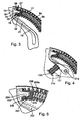
- the in the FIGS. 1 to 3 illustrated vibration damping device 1 comprises a torsional vibration damper 2, which is arranged in the illustrated embodiment between two flywheel elements 3, 4.
- the two flywheel elements 3, 4 are rotatable relative to each other via a bearing 5, centrally positioned.
- the flywheel element 3 can be connected to the output shaft of an internal combustion engine, for example, whereas the flywheel element 4 can be coupled to a transmission input shaft, for example via a friction clutch mounted on the flywheel element 4.
- the torsional vibration damper 2 comprises in the illustrated embodiment, two energy accumulators 6 formed by coil springs, which are integrally formed here.
- the energy storage 6 can only from a spring 6a or, as in the Figures 2 and 3 represented, consist of at least one outer spring 6a and at least one received therein inner spring 6b.
- a plurality of series-connected spring elements can be used to form energy storage, as for example by the DE-OS 41 28 868 and the DE-OS 43 01 311 animated has been.
- the energy storage 6 are accommodated in an annular or torus-like space 7, which can be filled in an advantageous manner, at least partially with a viscous medium, such as fat.
- the space 7 is mainly formed by two housing parts 8, 9, which are produced in the illustrated embodiment as sheet metal moldings and shell-like at least with respect to the coil springs 6a.
- the housing parts 8, 9 are tightly connected by means of a weld joint 10 extending over the entire circumference.
- the annular or torus-like space 7 is - viewed in the circumferential direction - divided into individual recordings in which the energy storage 6 are included.
- the individual recordings are - viewed in the circumferential direction - separated from each other by Beauftschungs Kunststoffe 11, 12, which are formed in the illustrated embodiment by in the formed as sheet metal parts housing parts 8, 9 projections, for example pocket-shaped embossments.
- the charging areas 13 for the energy accumulators 6 connected to the second flywheel element 4 are supported by a disk-like ring-like component 14, which is connected radially inwardly via rivet connections 15 to the second flywheel element 4.
- the loading regions 13 are formed by formed on the outer contour of the disk-like member 14 radial arm or arms.
- the arms 13 are arranged in the unclaimed vibration damping device 1 axially between the axially opposite loading regions 11, 12 of the first flywheel element 3.
- the end 16 of at least one energy storage device 6 is initially not acted upon by an arm 13, as between the corresponding end 16 of the energy storage 6 and the associated support areas 18 of an arm 13, an additional suspension, which is applied by a spring element 19, is provided.
- the spring action of the spring element 19 is connected in series with the spring action of the associated energy store 6.
- Abstützschalen 17 are provided, which, as from the Figures 2 and 3 it can be seen extending over at least the length of the energy storage 6.
- These support shells are preferably adapted to the contour of the turns of the outer coil spring 6a and serve as wear protection.
- the support shells 17 are made of spring steel or hardened steel.
- two energy storage 6 are provided, which may extend approximately over half the circumference of the vibration damping device 1.
- the disk-shaped component 14 has two diametrically opposite arms thirteenth
- the spring element 19 is integrally formed with the flange or disc-shaped member 14.
- a slot-shaped cutout 20 is introduced in the disk-shaped component 14, whereby an arm-shaped spring element 19 is formed.
- the length of the arm 21 thus formed is matched or dimensioned in relation to the over the length of the arm 21 viewed cross-sectional profile such that such an arm 21 forms a spring acting as a bending beam.
- the spring action generated by such an arm 21 is connected in series with the spring action of an energy store 6.
- the slot 20 is between the free end 22 of an arm 21 and the support or Beauftschungs Schemeen 18 of an arm 13 a defined circumferential distance 23 is formed.
- the effective travel of an arm 21 can be determined.
- this elastic arm 21 is supported in the illustrated embodiment, directly on the arm portions 13 a of an arm 13.
- the slot 20 is designed radially outward such that preferably at least partially a planar support between the radially outer regions 22 of an arm 21 and the support or Beaufschlagungs Schemeen 18 of the corresponding arm 13 takes place.
- the closed end 20a of a slot 20 and the transition regions 21a of an arm 21 are designed such that they ensure a fatigue strength of the component 14 in relation to the stresses occurring as a result of the elastic deformation of the corresponding arm 21.
- the slots 20 are formed such that due to an elastic deformation of an arm 22, a twist angle 23 in the order between 2 ° and 8 ° between the relative mutually rotatable components, which are formed here by the two flywheel elements 3 and 4, is made possible.
- the arms 21 have at its radially outer portion 22 a Anformung 24 which cooperates in the illustrated embodiment with the interposition of a spring plunger 25 with the correspondingly associated end 16 of an energy store 6 such that this end portion 16 against the centrifugal force acting on this can be radially supported.
- this Anformung 24 is formed by a circumferentially extending pin or by a nose 24 which can engage in a circumferential recess or recess 26 of a spring cup 25.
- the respective nose 24 and the associated recess 26 are formed and arranged with respect to each other such that at least in an elastic deformation of the corresponding arm 21 of the energy storage 6 with respect to the radially outer regions 27, at which the turns of the coil spring 6a are supported under centrifugal force, withheld or lifted off.
- a corresponding lift 28 is off FIG. 3 refer to.
- the radially inner region of a nose 24 forms a ramp ramp-like slope 30, which cooperates with a support region 31 of a spring cap 25.
- a perfect threading of the nose 24 is ensured in the recess 26.
- contours of a nose 24 and the associated recess 26 may be formed with respect to each other in such a way that even when threading the nose 24 into the recess 26, a certain radial displacement of the corresponding spring end 16 can take place.
- the aforementioned contours and countercontours are coordinated with one another in such a way that initially virtually complete threading of a nose 24 into the corresponding recess 26 can take place without the corresponding spring end 16 being pulled radially inward. This ensures that a radial retraction of the corresponding spring end 16 only takes place due to the deformation of this arm 21 taking place by acting on the associated spring arm 21.
- the aforementioned radial retraction of the spring ends 16 has the advantage that even at higher speeds, at least the end regions, that is, some turns of the energy storage or here the outer coil spring 6a, outside out of contact with other components or areas are kept, so that These spring coils can spring freely, which means that virtually no frictional damping generate.
- At least one end portion of a coil spring 6a still has an elasticity or suspension. This is particularly advantageous in order to dampen the high frequency oscillations occurring in these speed ranges with a small angular amplitude.
- the radially disposed inside the outer coil spring 6a inner coil spring 6b is also acted upon by at least one spring plunger 25.
- the respective spring cup 25 has a projection 32 which extends in the circumferential direction into the end region of the corresponding spring 6a and which also delimits a recess 26.
- the respective spring cap 25 is formed such that its projection 32 at its outer portions 22 of an arm 21 end facing an annular radial collar 33, on which the associated end of a spring 6a is supported in the circumferential direction.
- FIG. 3 how out FIG. 3 can be seen, some of the opposite the outer support or guide surface 27 lifted turns of the outer spring 6a can be supported radially under centrifugal force on the projection 32 of the corresponding spring cup 25, which in turn creates a certain friction between these spring coils and the neck 32.
- the axial projection 32 forming material and / or by a corresponding coating the resulting friction damping, however, can be kept smaller than that which would arise by supporting these turns on the surface 27.
- the radial displacement of a spring end by means of a pivotable arm can, as already mentioned, advantageously be used for those spring ends which pass through the flange 14 are applied in overrun operation.
- the radial retraction of spring ends by means of pivotable arms can also find application for those spring ends, which are acted upon by the flange 14 in traction operation.
- an arm 21 has a circumferentially directed Anformung 24, which enters a recess 26 of a spring cap 25.
- the spring cup 25 has an integrally formed, suitably designed for the purpose, which engages in a recess in the region of an arm 21 to ensure the desired radial displacement of the corresponding spring end.
- a corresponding resilient arm 21 is formed with respect to its shape and its spring properties such that it does not come into contact with the surface 27 under centrifugal force.
- the illustrated lever arms 21 are integrally formed with the flange 14 forming the biasing portions 13, such resilient arms 21 may also be formed by an additional component. This can be done in a similar way, as for example in the DE 44 33 467 , in particular in connection with the FIGS. 1 to 4 or in the DE 101 19 878 , in particular in connection with the FIGS. 1 to 5 , has been described.
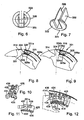
- the pivotable lever 121 is formed by at least one separate component which is mounted pivotably about a rotation axis 121 a.
- the lever 121 is pivotally mounted on the flange-shaped component 114.
- the lever arm 121 can be pivoted against the action of an energy storage, which is symbolized here by a helical spring 134.
- FIG. 4 an operating state is shown, which corresponds to the in FIG. 3 represented corresponds.
- the energy storage 134 may be supported on a region 114 connected to the flange 114. However, this area 135 can also be provided on another component, which is non-rotatable with the flange 114.
- a coil spring 134 and at least one leg spring or leaf spring could be used.
- the one leg of such a spring can be mounted, for example, rotationally fixed in a corresponding opening of the flange 114, whereas the other leg opposes a rotation resistance of the lever 121.
- a corresponding stop for example on the flange 114, can be provided.
- Such a stop may be formed, for example, by an integrally formed with the flange 114 nose, which has an axial region on which the lever 121 can be supported.
- the lever 121 could have an axially protruding projection which engages in a correspondingly formed, the necessary pivoting of the arm 121 ensuring recess.
- a nose or recess could for example be provided in the axially overlapping regions of the lever 121 and the flange 114.
- the tendency to pivoting a lever arm 21 and 121 required force can also be influenced by appropriate mass design of such a lever element.
- the one end of an energy storage 6 associated spring cup 25 can be captive or firmly connected to the corresponding end of the energy storage. This can be done for example by means of a positive connection that can be configured as a snap connection. In this regard, for example, on the DE 196 03 248 A1 directed. Such connection may exist between the corresponding spring cup and the outer coil spring 6a and / or, if an inner coil spring 6b is present, between this spring cup and this inner coil spring 6b.
- a certain grid effect or a positive connection after threading a nose 224 in the corresponding spring cap 225 may be present.
- such a connection is ensured by means of a latching connection 236.
- the ramp 233 of the nose 224 and the cooperating with this counter contour 231 of the spring cap 225 is designed graduated according to, so that the contours formed thereby - when viewed in the circumferential direction - radially engage behind, creating a certain positive connection.
- Such a force-limited locking between a pivotable arm 221 and the corresponding end of an energy storage 206 and a spring tap 225 also allows a stress of the corresponding energy storage or the coil spring forming this 206a to train.
- the torque transferable via such a ratchet 236 is, as already mentioned, dependent on the force-related connection between the corresponding components or regions 221, 225 and 227 ensured by such rastering 236 206a.
- centrifugal force necessary to solve such a grid connection 236 force is also centrifugal force, so speed dependent.
- FIGS. 2 to 5 illustrated embodiments also have the advantage that during the radial retraction of the energy storage end 16 no relative movement between the spring cup 25 and the lever arm 21 and the nose 24 takes place, whereby a related wear can be avoided.
- the embodiment according to the invention also makes it possible, by suitable coordination of the mass or mass distribution of a lever 121, to build up a speed-dependent torque between the corresponding lever and the associated energy storage end, which must be overcome by the circumferential force occurring during the compression of an energy store.
- a speed-dependent torque between the corresponding lever and the associated energy storage end, which must be overcome by the circumferential force occurring during the compression of an energy store.
- it may be the Abhebeverlauf an energy storage end 16 is controlled as a function of the applied torsional or engine torque and associated speed.
- the in the FIGS. 6 to 9 illustrated spring cup 325 differs from the previously described spring cups essentially in that the free space or the recess 326 for receiving a radial Abstütznase 324 radially outwardly at least over a portion of its circumferential extent is radially outwardly open.
- the free space or the recess 326 is slot-shaped or channel-like and in the illustrated embodiment over the entire circumferential extent radially outwardly open.
- embodiments are also conceivable in which, starting from the end collar 333, the free space 326 extends only over a partial region of the shoulder 332 engaging in a spring end.
- the collar 333 serves, as has already been described in connection with the other spring cups, for supporting a spring end.
- FIGS. 8 and 9 It can be seen that the nose 324 and the radially inner portions 325a of a spring cap 325 adjacent the clearance 326 form correspondingly matched ramps 331, 331a which cooperate such that upon compression of the corresponding spring 306a by means of the nose 324 carrying flange 314, the corresponding spring end 316 is pulled radially inwardly, in a similar manner, as in connection with the FIGS. 1 to 5 has been described. This should also be ensured a free suspension of the corresponding spring end 316.
- the nose 324 is rigidly formed with the flange 314.
- a nose can also in a similar manner, as in connection with the FIGS. 1 to 5 has been described, be formed on a pivotable arm 121, which is supported by a corresponding flange or disc-shaped component.
- An at least partial opening of the recess or the free space 326 allows a freer design of the nose 324, since at least in the collar 333 adjacent portions of a projection 332, the nose 324 can be made wider in the radial direction and thus, at least in this area, a can have higher bending stiffness. So you get through an appropriate design of a spring cup 325 additional radial space for a nose 324, whereby longer lugs 324 are possible at least the same strength.
- a spring cap 325 also makes it possible to make the radially inner, cooperating with a nose 324 support portions 325a of a cup 325 thicker material thickness, whereby the strength of the cup against centrifugal forces which are exerted by the spring 306a on this, improved can.
- an end portion of a spring 306a voltages can be limited to an acceptable level.
- an end portion of a spring 306a voltages can be determined.
- the present radially within a nose 324 spring loading areas 324a of the flange 314 and the radially outside of the nose 324 existing spring loading areas 324b are arranged offset in the circumferential direction of the damping device 301 to each other.
- this offset between the loading areas 324a and 324b is dimensioned such that these practically at the same time on the one hand on the collar 333 of the spring cup 325 and on the other hand the end turn 316a of the spring 316 come to rest.
- the collar 333 is also interrupted or set back in the circumferential direction in the area of the radially inner loading area 324a of the flange 314, in such a way that immediate support of the end turn 316a on the area 324a of the flange is ensured ,
- the loading region 324a, 324b of the flange 314, viewed in the radial direction, can then be aligned.
- FIGS. 10 to 12 Also shown supporting member 425 also allows a radial support of the end turns of a spring end 416 in a similar manner, as described in connection with the spring cup 325.
- FIG. 12 It can be seen that in the illustrated embodiment, the effective as ramps and counter-ramps surfaces 431 of the flange nose 424 and 431 a of the support element 425 matched to one another such that during the immersion phase of the flange nose 424 in the cross-sectionally U-shaped support member 425 is always a surface contact between the two surfaces 431 and 431 a is present. As a result, the wear occurring on these surfaces can be substantially reduced.
- the surfaces 431 and 431 a are arc-shaped and designed in accordance with the axis of rotation of the vibration damping device according to ensure surface contact.
- the illustrated embodiment is suitable for manufacture from sheet material.
- the sheet or the support member 425 may be coated at least on this surface 431 a with a sliding material.
- the support element 425 is hardened at least in the area of the surface 431 a.
- the production of elements 425 made of sheet metal has the advantage that they can be produced by simple forming, ie without cutting. This allows a cost-effective production of such support elements.
- the support member 425 is, as already mentioned, designed in cross-section U-shaped and has two tabs or tongues 434, 435, which protrude laterally. These tongues 434, 435 are supported on the end turn 436 of the corresponding spring, as is apparent FIG. 12 can be seen.
- the regions 434, 435 simultaneously serve to act on the spring end region 416.
- this support element 425 has corresponding cutouts 437.
- FIGS. 10 and 11 has a support member 425 projections 438, which are here formed by tab-shaped portions 438, which are deformed with respect to the remaining portions of a support member 425 such that they protrude into the space 426 formed by the U-shaped configuration of the support member 425.
- the regions 438 form support surfaces on which the nose 424 of the flange 414 comes into contact with a mating surface, which may be formed by a step, for example.
- a support member 425 has a Anformung 439, which forms a radially inwardly directed nose 439 here.
- This Anformung 439 attacks, as is the case FIG. 12 is removable, between two turns of the spring end 416, whereby a captive between the corresponding spring end 416 and the associated support member 425 is ensured.
Landscapes
- Engineering & Computer Science (AREA)
- General Engineering & Computer Science (AREA)
- Physics & Mathematics (AREA)
- Acoustics & Sound (AREA)
- Aviation & Aerospace Engineering (AREA)
- Mechanical Engineering (AREA)
- Mechanical Operated Clutches (AREA)
- Buildings Adapted To Withstand Abnormal External Influences (AREA)
- Surgical Instruments (AREA)
- Vibration Prevention Devices (AREA)
Claims (10)
- Amortisseur de vibrations de torsion avec une partie d'entrée et une partie de sortie, qui peuvent tourner l'une par rapport à l'autre dans le sens contraire à l'effet d'accumulateurs d'énergie efficaces entre ces parties, les accumulateurs d'énergie présentant au moins un ressort hélicoïdal compressible et disposé largement dans le sens périphérique de l'amortisseur, également au moins un élément de levier basculant dans le sens périphérique étant porté par l'une des pièces, le ressort hélicoïdal pouvant s'appuyer par l'une de ses extrémités côté pourtour sur l'élément de levier au moins lors d'une rotation relative entre la partie d'entrée et la partie de sortie de telle sorte qu'il est basculé du fait de la rotation relative par rapport à la partie portant cet élément, l'élément de levier présentant des contours qui coopèrent avec des contre-contours prévus sur l'extrémité attribuée du ressort hélicoïdal de telle sorte qu'au moins un tronçon d'extrémité du ressort hélicoïdal est retenu en arrière radialement pendant le basculement côté pourtour de l'élément de levier contrairement à la force centrifuge agissant sur ce tronçon de ressort, l'élément de levier étant logé de façon à pouvoir basculer sur la partie d'entrée et/ou la partie de sortie et pouvant être basculé autour de son logement dans le sens contraire à l'effet d'un accumulateur d'énergie supplémentaire distinct de l'élément de levier.
- Amortisseur de vibrations de torsion selon la revendication 1, caractérisé en ce que la partie d'entrée ou la partie de sortie est formée par un composant en forme de bride qui porte le au moins un élément de levier.
- Amortisseur de vibrations de torsion selon l'une quelconque des revendications 1 à 2, caractérisé en ce que l'élément de levier basculant dans le sens contraire à un effet de ressort et le ressort hélicoïdal sont montés en série au niveau de l'effet entre la partie d'entrée et la partie de sortie.
- Amortisseur de vibrations de torsion selon l'une quelconque des revendications 1 à 3, caractérisé en ce que le ressort hélicoïdal s'étend dans le sens périphérique de l'amortisseur de vibrations de torsion et génère à l'intérieur de l'amortisseur de vibrations de torsion un frottement dépendant de la force centrifuge et monté parallèlement à l'effet de ressort du ressort hélicoïdal, de sorte que la résistance à la torsion dynamique est générée globalement par le ressort hélicoïdal est dépendante du régime.
- Amortisseur de vibrations de torsion selon l'une quelconque des revendications 1 à 4, caractérisé en ce que la partie de sortie et la partie d'entrée présentent une paroi recouvrant axialement le ressort hélicoïdal, sur laquelle le ressort hélicoïdal s'appuie soit directement au moyen de ses spires soit indirectement au moyen de parties de soutien intercalées au moins sous l'effet de la force centrifuge.
- Amortisseur de vibrations de torsion selon l'une quelconque des revendications 1 à 5, caractérisé en ce que le ressort hélicoïdal porte au moins sur son extrémité coopérant avec un élément de levier une position intermédiaire qui forme les contre-contours lesquels coopèrent avec les contours de l'élément de levier.
- Amortisseur de vibrations de torsion selon l'une quelconque des revendications 1 à 6, caractérisé en ce que l'élément de levier peut basculer de telle sorte que ses contours de retenue sont déplacés pendant le basculement sur une trajectoire de mouvement qui présente une distance variable par rapport à l'axe de rotation du dispositif d'amortissement.
- Amortisseur de vibrations de torsion selon les revendications 1 à 7, caractérisé en ce que l'élément de levier peut basculer de telle sorte que, lors d'un basculement de l'élément de levier en raison d'une sollicitation côté pourtour par le ressort hélicoïdal, les contours de soutien de l'élément de levier sont déplacés le long d'une trajectoire de mouvement de telle sorte que leur distance à l'axe de rotation de l'amortisseur de vibrations de torsion se réduit, de sorte que l'extrémité de ressort correspondante est refoulée en direction de l'axe de rotation.
- Amortisseur de vibrations de torsion selon l'une quelconque des revendications 1 à 8, caractérisé en ce que les contours de l'élément de levier sont formés au moins par une partie formée en forme d'ergot, s'étendant dans le sens périphérique.
- Amortisseur de vibrations de torsion selon l'une quelconque des revendications 1 à 9, caractérisé en ce que les contre-contours prévus sur l'extrémité de ressort correspondante sont formés par un évidement d'une position intermédiaire prévue sur l'extrémité de ressort correspondante.
Applications Claiming Priority (3)
| Application Number | Priority Date | Filing Date | Title |
|---|---|---|---|
| DE102004037416 | 2004-07-30 | ||
| DE102004045113 | 2004-09-17 | ||
| DE102004059457 | 2004-12-10 |
Publications (3)
| Publication Number | Publication Date |
|---|---|
| EP1621796A1 EP1621796A1 (fr) | 2006-02-01 |
| EP1621796B1 EP1621796B1 (fr) | 2007-10-24 |
| EP1621796B2 true EP1621796B2 (fr) | 2011-10-26 |
Family
ID=34993144
Family Applications (1)
| Application Number | Title | Priority Date | Filing Date |
|---|---|---|---|
| EP05015846A Not-in-force EP1621796B2 (fr) | 2004-07-30 | 2005-07-21 | Amortisseur de vibrations de torsion |
Country Status (3)
| Country | Link |
|---|---|
| EP (1) | EP1621796B2 (fr) |
| AT (1) | ATE376634T1 (fr) |
| DE (1) | DE502005001767D1 (fr) |
Cited By (3)
| Publication number | Priority date | Publication date | Assignee | Title |
|---|---|---|---|---|
| US10041578B2 (en) | 2013-07-25 | 2018-08-07 | Litens Automotive Partnership | Spring assembly for isolator |
| US10060502B2 (en) | 2012-10-12 | 2018-08-28 | Litens Automotive Partnership | Isolator for use with engine that is assisted or started by an MGU or a motor through an endless drive member |
| US10125856B2 (en) | 2013-11-10 | 2018-11-13 | Litens Automotive Partnership | Isolator with dual springs |
Families Citing this family (8)
| Publication number | Priority date | Publication date | Assignee | Title |
|---|---|---|---|---|
| WO2008145959A1 (fr) * | 2007-05-31 | 2008-12-04 | Automotive Products S.P.A. | Plaques entraînées par embrayage |
| DE102009039997A1 (de) * | 2008-09-22 | 2010-03-25 | Luk Lamellen Und Kupplungsbau Beteiligungs Kg | Drehschwingungsdämpfer |
| JP5458612B2 (ja) | 2009-03-13 | 2014-04-02 | アイシン精機株式会社 | ダンパ装置 |
| JP5772983B2 (ja) * | 2011-12-22 | 2015-09-02 | トヨタ自動車株式会社 | 捩り振動減衰装置 |
| CN105393024B (zh) | 2013-05-23 | 2018-04-03 | 利滕斯汽车合伙公司 | 降低噪音的具有双作用弹簧系统的隔离器 |
| US10267405B2 (en) | 2013-07-24 | 2019-04-23 | Litens Automotive Partnership | Isolator with improved damping structure |
| DE102018207838A1 (de) * | 2018-05-18 | 2019-11-21 | Audi Ag | Zweimassenschwungrad |
| DE102019120001A1 (de) * | 2019-07-24 | 2021-01-28 | Schaeffler Technologies AG & Co. KG | Drehschwingungsdämpfer |
Citations (2)
| Publication number | Priority date | Publication date | Assignee | Title |
|---|---|---|---|---|
| EP0236159A1 (fr) † | 1986-01-22 | 1987-09-09 | Valeo | Volant amortisseur pour transmission, notamment pour véhicule automobile |
| DE10019873A1 (de) † | 1999-04-22 | 2001-04-19 | Aisin Seiki | Drehmomentänderungsabsorptionsvorrichtung |
Family Cites Families (16)
| Publication number | Priority date | Publication date | Assignee | Title |
|---|---|---|---|---|
| GB511798A (en) * | 1938-02-25 | 1939-08-24 | Noel Banner Newton | Improvements in or relating to clutch plates |
| GB2217429B (en) | 1988-03-26 | 1991-12-18 | Luk Lamellen & Kupplungsbau | Apparatus for damping vibrations |
| DE4117579B4 (de) | 1990-05-31 | 2007-07-12 | Luk Lamellen Und Kupplungsbau Beteiligungs Kg | Drehmomentübertragungseinrichtung |
| DE4117571A1 (de) | 1990-05-31 | 1991-12-05 | Luk Lamellen & Kupplungsbau | Geteiltes schwungrad |
| FR2676789A1 (fr) * | 1991-05-23 | 1992-11-27 | Valeo | Amortisseur de torsion, notamment pour vehicules automobiles. |
| DE4128868A1 (de) | 1991-08-30 | 1993-03-04 | Fichtel & Sachs Ag | Zweimassenschwungrad mit gleitschuh |
| FR2698933B1 (fr) * | 1992-12-09 | 1995-03-10 | Valeo | Amortisseur de torsion, notamment pour véhicule automobile. |
| DE4301311C2 (de) | 1993-01-20 | 2002-10-10 | Zf Sachs Ag | Gleitlagerung für Zwei-Massen-Schwungrad |
| DE4433467C2 (de) | 1993-09-28 | 2003-04-17 | Luk Lamellen & Kupplungsbau | Torsionsschwingungsdämpfer |
| DE19603248B4 (de) | 1995-02-03 | 2011-09-22 | Schaeffler Technologies Gmbh & Co. Kg | Drehschwingungsdämpfer |
| DE19648342B4 (de) | 1995-12-14 | 2010-10-21 | Luk Lamellen Und Kupplungsbau Beteiligungs Kg | Drehschwingungsdämpfer |
| DE19909044B4 (de) | 1998-03-07 | 2018-06-21 | Schaeffler Technologies AG & Co. KG | Drehschwingungsdämpfer |
| AU4130399A (en) | 1998-03-25 | 1999-10-18 | Luk Lamellen Und Kupplungsbau Gmbh | Torsional vibration damper and helical compression spring for a torsional vibration damper |
| DE10119878B4 (de) | 2000-05-17 | 2013-02-07 | Schaeffler Technologies AG & Co. KG | Torsionsschwingunsdämpfer |
| DE10209838B4 (de) | 2001-03-14 | 2013-07-11 | Schaeffler Technologies AG & Co. KG | Drehschwingungsdämpfer |
| DE10294359D2 (de) | 2001-09-17 | 2004-07-29 | Luk Lamellen & Kupplungsbau | Drehschwingungsdämpfer |
-
2005
- 2005-07-21 DE DE502005001767T patent/DE502005001767D1/de active Active
- 2005-07-21 AT AT05015846T patent/ATE376634T1/de not_active IP Right Cessation
- 2005-07-21 EP EP05015846A patent/EP1621796B2/fr not_active Not-in-force
Patent Citations (2)
| Publication number | Priority date | Publication date | Assignee | Title |
|---|---|---|---|---|
| EP0236159A1 (fr) † | 1986-01-22 | 1987-09-09 | Valeo | Volant amortisseur pour transmission, notamment pour véhicule automobile |
| DE10019873A1 (de) † | 1999-04-22 | 2001-04-19 | Aisin Seiki | Drehmomentänderungsabsorptionsvorrichtung |
Cited By (3)
| Publication number | Priority date | Publication date | Assignee | Title |
|---|---|---|---|---|
| US10060502B2 (en) | 2012-10-12 | 2018-08-28 | Litens Automotive Partnership | Isolator for use with engine that is assisted or started by an MGU or a motor through an endless drive member |
| US10041578B2 (en) | 2013-07-25 | 2018-08-07 | Litens Automotive Partnership | Spring assembly for isolator |
| US10125856B2 (en) | 2013-11-10 | 2018-11-13 | Litens Automotive Partnership | Isolator with dual springs |
Also Published As
| Publication number | Publication date |
|---|---|
| EP1621796A1 (fr) | 2006-02-01 |
| DE502005001767D1 (de) | 2007-12-06 |
| ATE376634T1 (de) | 2007-11-15 |
| EP1621796B1 (fr) | 2007-10-24 |
Similar Documents
| Publication | Publication Date | Title |
|---|---|---|
| EP1621796B2 (fr) | Amortisseur de vibrations de torsion | |
| DE19721236B4 (de) | Torsionsschwingungsdämpfer | |
| DE19909044B4 (de) | Drehschwingungsdämpfer | |
| EP1662173B1 (fr) | Amortisseur d'oscillations de torsion | |
| DE102004006879B4 (de) | Drehschwingungsdämpfer | |
| DE19734322B4 (de) | Torsionsschwingungsdämpfer mit Wälzkörpern als Koppelelemente | |
| DE10209838B4 (de) | Drehschwingungsdämpfer | |
| DE3608829A1 (de) | Einrichtung zum kompensieren von drehstoessen | |
| DE102012218918A1 (de) | Drehschwingungsdämpfungsanordnung mit drehzahlabhängiger Charakteristik | |
| DE102008009656A1 (de) | Torsionsschwingungsdämpfer | |
| EP1812728B1 (fr) | Dispositif de transmission de couple de rotation | |
| WO2015043587A1 (fr) | Dispositif pendulaire centrifuge | |
| DE8535705U1 (de) | Einrichtung zum Kompensieren von Drehstößen | |
| DE3616301A1 (de) | Torsionsschwingungsdaempfer | |
| EP3728893A1 (fr) | Pendule centrifuge | |
| DE3616163A1 (de) | Torsionsschwingungsdaempfer | |
| DE102013210637A1 (de) | Schwingungstilger mit universeller Charakteristik | |
| DE102005034049A1 (de) | Torsionsschwingungsdämpfer | |
| DE102004022511B4 (de) | Kupplungsvorrichtung, insbesondere für ein Kraftfahrzeug | |
| DE19819824A1 (de) | Torsionsschwingungsdämpfer mit einer Dämpfungseinrichtung | |
| DE102006008362B4 (de) | Dämpfer für Verbrennungsmotor | |
| DE10119878B4 (de) | Torsionsschwingunsdämpfer | |
| DE102006015134B4 (de) | Drehschwingungdämpfer | |
| DE102009010137A1 (de) | Drehschwingungsdämpfer und Energiespeicher für einen solchen | |
| DE19734726C1 (de) | Torsionsschwingungsdämpfer |
Legal Events
| Date | Code | Title | Description |
|---|---|---|---|
| PUAI | Public reference made under article 153(3) epc to a published international application that has entered the european phase |
Free format text: ORIGINAL CODE: 0009012 |
|
| AK | Designated contracting states |
Kind code of ref document: A1 Designated state(s): AT BE BG CH CY CZ DE DK EE ES FI FR GB GR HU IE IS IT LI LT LU LV MC NL PL PT RO SE SI SK TR |
|
| AX | Request for extension of the european patent |
Extension state: AL BA HR MK YU |
|
| 17P | Request for examination filed |
Effective date: 20060801 |
|
| AKX | Designation fees paid |
Designated state(s): AT BE BG CH CY CZ DE DK EE ES FI FR GB GR HU IE IS IT LI LT LU LV MC NL PL PT RO SE SI SK TR |
|
| GRAP | Despatch of communication of intention to grant a patent |
Free format text: ORIGINAL CODE: EPIDOSNIGR1 |
|
| GRAS | Grant fee paid |
Free format text: ORIGINAL CODE: EPIDOSNIGR3 |
|
| GRAA | (expected) grant |
Free format text: ORIGINAL CODE: 0009210 |
|
| AK | Designated contracting states |
Kind code of ref document: B1 Designated state(s): AT BE BG CH CY CZ DE DK EE ES FI FR GB GR HU IE IS IT LI LT LU LV MC NL PL PT RO SE SI SK TR |
|
| REG | Reference to a national code |
Ref country code: GB Ref legal event code: FG4D Free format text: NOT ENGLISH |
|
| REG | Reference to a national code |
Ref country code: CH Ref legal event code: EP |
|
| REG | Reference to a national code |
Ref country code: IE Ref legal event code: FG4D Free format text: LANGUAGE OF EP DOCUMENT: GERMAN |
|
| REF | Corresponds to: |
Ref document number: 502005001767 Country of ref document: DE Date of ref document: 20071206 Kind code of ref document: P |
|
| NLV1 | Nl: lapsed or annulled due to failure to fulfill the requirements of art. 29p and 29m of the patents act | ||
| PLBI | Opposition filed |
Free format text: ORIGINAL CODE: 0009260 |
|
| PG25 | Lapsed in a contracting state [announced via postgrant information from national office to epo] |
Ref country code: ES Free format text: LAPSE BECAUSE OF FAILURE TO SUBMIT A TRANSLATION OF THE DESCRIPTION OR TO PAY THE FEE WITHIN THE PRESCRIBED TIME-LIMIT Effective date: 20080204 Ref country code: SE Free format text: LAPSE BECAUSE OF FAILURE TO SUBMIT A TRANSLATION OF THE DESCRIPTION OR TO PAY THE FEE WITHIN THE PRESCRIBED TIME-LIMIT Effective date: 20080124 Ref country code: NL Free format text: LAPSE BECAUSE OF FAILURE TO SUBMIT A TRANSLATION OF THE DESCRIPTION OR TO PAY THE FEE WITHIN THE PRESCRIBED TIME-LIMIT Effective date: 20071024 |
|
| 26 | Opposition filed |
Opponent name: ZF SACHS AG Effective date: 20080407 |
|
| GBV | Gb: ep patent (uk) treated as always having been void in accordance with gb section 77(7)/1977 [no translation filed] | ||
| PG25 | Lapsed in a contracting state [announced via postgrant information from national office to epo] |
Ref country code: BG Free format text: LAPSE BECAUSE OF FAILURE TO SUBMIT A TRANSLATION OF THE DESCRIPTION OR TO PAY THE FEE WITHIN THE PRESCRIBED TIME-LIMIT Effective date: 20080124 Ref country code: SI Free format text: LAPSE BECAUSE OF FAILURE TO SUBMIT A TRANSLATION OF THE DESCRIPTION OR TO PAY THE FEE WITHIN THE PRESCRIBED TIME-LIMIT Effective date: 20071024 Ref country code: IS Free format text: LAPSE BECAUSE OF FAILURE TO SUBMIT A TRANSLATION OF THE DESCRIPTION OR TO PAY THE FEE WITHIN THE PRESCRIBED TIME-LIMIT Effective date: 20080224 Ref country code: PT Free format text: LAPSE BECAUSE OF FAILURE TO SUBMIT A TRANSLATION OF THE DESCRIPTION OR TO PAY THE FEE WITHIN THE PRESCRIBED TIME-LIMIT Effective date: 20080324 Ref country code: PL Free format text: LAPSE BECAUSE OF FAILURE TO SUBMIT A TRANSLATION OF THE DESCRIPTION OR TO PAY THE FEE WITHIN THE PRESCRIBED TIME-LIMIT Effective date: 20071024 Ref country code: LT Free format text: LAPSE BECAUSE OF FAILURE TO SUBMIT A TRANSLATION OF THE DESCRIPTION OR TO PAY THE FEE WITHIN THE PRESCRIBED TIME-LIMIT Effective date: 20071024 Ref country code: LV Free format text: LAPSE BECAUSE OF FAILURE TO SUBMIT A TRANSLATION OF THE DESCRIPTION OR TO PAY THE FEE WITHIN THE PRESCRIBED TIME-LIMIT Effective date: 20071024 |
|
| REG | Reference to a national code |
Ref country code: IE Ref legal event code: FD4D |
|
| ET | Fr: translation filed | ||
| PG25 | Lapsed in a contracting state [announced via postgrant information from national office to epo] |
Ref country code: DK Free format text: LAPSE BECAUSE OF FAILURE TO SUBMIT A TRANSLATION OF THE DESCRIPTION OR TO PAY THE FEE WITHIN THE PRESCRIBED TIME-LIMIT Effective date: 20071024 Ref country code: CZ Free format text: LAPSE BECAUSE OF FAILURE TO SUBMIT A TRANSLATION OF THE DESCRIPTION OR TO PAY THE FEE WITHIN THE PRESCRIBED TIME-LIMIT Effective date: 20071024 |
|
| PLAX | Notice of opposition and request to file observation + time limit sent |
Free format text: ORIGINAL CODE: EPIDOSNOBS2 |
|
| PG25 | Lapsed in a contracting state [announced via postgrant information from national office to epo] |
Ref country code: RO Free format text: LAPSE BECAUSE OF FAILURE TO SUBMIT A TRANSLATION OF THE DESCRIPTION OR TO PAY THE FEE WITHIN THE PRESCRIBED TIME-LIMIT Effective date: 20071024 Ref country code: SK Free format text: LAPSE BECAUSE OF FAILURE TO SUBMIT A TRANSLATION OF THE DESCRIPTION OR TO PAY THE FEE WITHIN THE PRESCRIBED TIME-LIMIT Effective date: 20071024 |
|
| PG25 | Lapsed in a contracting state [announced via postgrant information from national office to epo] |
Ref country code: IE Free format text: LAPSE BECAUSE OF FAILURE TO SUBMIT A TRANSLATION OF THE DESCRIPTION OR TO PAY THE FEE WITHIN THE PRESCRIBED TIME-LIMIT Effective date: 20071024 |
|
| PG25 | Lapsed in a contracting state [announced via postgrant information from national office to epo] |
Ref country code: GB Free format text: LAPSE BECAUSE OF FAILURE TO SUBMIT A TRANSLATION OF THE DESCRIPTION OR TO PAY THE FEE WITHIN THE PRESCRIBED TIME-LIMIT Effective date: 20071024 |
|
| PG25 | Lapsed in a contracting state [announced via postgrant information from national office to epo] |
Ref country code: GR Free format text: LAPSE BECAUSE OF FAILURE TO SUBMIT A TRANSLATION OF THE DESCRIPTION OR TO PAY THE FEE WITHIN THE PRESCRIBED TIME-LIMIT Effective date: 20080125 |
|
| PLAF | Information modified related to communication of a notice of opposition and request to file observations + time limit |
Free format text: ORIGINAL CODE: EPIDOSCOBS2 |
|
| PG25 | Lapsed in a contracting state [announced via postgrant information from national office to epo] |
Ref country code: FI Free format text: LAPSE BECAUSE OF FAILURE TO SUBMIT A TRANSLATION OF THE DESCRIPTION OR TO PAY THE FEE WITHIN THE PRESCRIBED TIME-LIMIT Effective date: 20071024 |
|
| PLBB | Reply of patent proprietor to notice(s) of opposition received |
Free format text: ORIGINAL CODE: EPIDOSNOBS3 |
|
| PG25 | Lapsed in a contracting state [announced via postgrant information from national office to epo] |
Ref country code: MC Free format text: LAPSE BECAUSE OF NON-PAYMENT OF DUE FEES Effective date: 20080731 |
|
| PG25 | Lapsed in a contracting state [announced via postgrant information from national office to epo] |
Ref country code: EE Free format text: LAPSE BECAUSE OF FAILURE TO SUBMIT A TRANSLATION OF THE DESCRIPTION OR TO PAY THE FEE WITHIN THE PRESCRIBED TIME-LIMIT Effective date: 20071024 |
|
| PG25 | Lapsed in a contracting state [announced via postgrant information from national office to epo] |
Ref country code: CY Free format text: LAPSE BECAUSE OF FAILURE TO SUBMIT A TRANSLATION OF THE DESCRIPTION OR TO PAY THE FEE WITHIN THE PRESCRIBED TIME-LIMIT Effective date: 20071024 |
|
| PG25 | Lapsed in a contracting state [announced via postgrant information from national office to epo] |
Ref country code: AT Free format text: LAPSE BECAUSE OF NON-PAYMENT OF DUE FEES Effective date: 20080721 |
|
| REG | Reference to a national code |
Ref country code: CH Ref legal event code: PL |
|
| PG25 | Lapsed in a contracting state [announced via postgrant information from national office to epo] |
Ref country code: LI Free format text: LAPSE BECAUSE OF NON-PAYMENT OF DUE FEES Effective date: 20090731 Ref country code: CH Free format text: LAPSE BECAUSE OF NON-PAYMENT OF DUE FEES Effective date: 20090731 |
|
| PG25 | Lapsed in a contracting state [announced via postgrant information from national office to epo] |
Ref country code: HU Free format text: LAPSE BECAUSE OF FAILURE TO SUBMIT A TRANSLATION OF THE DESCRIPTION OR TO PAY THE FEE WITHIN THE PRESCRIBED TIME-LIMIT Effective date: 20080425 Ref country code: BE Free format text: LAPSE BECAUSE OF NON-PAYMENT OF DUE FEES Effective date: 20080731 Ref country code: LU Free format text: LAPSE BECAUSE OF NON-PAYMENT OF DUE FEES Effective date: 20080721 |
|
| PG25 | Lapsed in a contracting state [announced via postgrant information from national office to epo] |
Ref country code: TR Free format text: LAPSE BECAUSE OF FAILURE TO SUBMIT A TRANSLATION OF THE DESCRIPTION OR TO PAY THE FEE WITHIN THE PRESCRIBED TIME-LIMIT Effective date: 20071024 |
|
| RAP2 | Party data changed (patent owner data changed or rights of a patent transferred) |
Owner name: SCHAEFFLER TECHNOLOGIES GMBH & CO. KG |
|
| PG25 | Lapsed in a contracting state [announced via postgrant information from national office to epo] |
Ref country code: IT Free format text: LAPSE BECAUSE OF NON-PAYMENT OF DUE FEES Effective date: 20080731 |
|
| APBM | Appeal reference recorded |
Free format text: ORIGINAL CODE: EPIDOSNREFNO |
|
| APBP | Date of receipt of notice of appeal recorded |
Free format text: ORIGINAL CODE: EPIDOSNNOA2O |
|
| APAH | Appeal reference modified |
Free format text: ORIGINAL CODE: EPIDOSCREFNO |
|
| APBU | Appeal procedure closed |
Free format text: ORIGINAL CODE: EPIDOSNNOA9O |
|
| PUAH | Patent maintained in amended form |
Free format text: ORIGINAL CODE: 0009272 |
|
| STAA | Information on the status of an ep patent application or granted ep patent |
Free format text: STATUS: PATENT MAINTAINED AS AMENDED |
|
| 27A | Patent maintained in amended form |
Effective date: 20111026 |
|
| AK | Designated contracting states |
Kind code of ref document: B2 Designated state(s): AT BE BG CH CY CZ DE DK EE ES FI FR GB GR HU IE IS IT LI LT LU LV MC NL PL PT RO SE SI SK TR |
|
| REG | Reference to a national code |
Ref country code: DE Ref legal event code: R102 Ref document number: 502005001767 Country of ref document: DE |
|
| REG | Reference to a national code |
Ref country code: DE Ref legal event code: R102 Ref document number: 502005001767 Country of ref document: DE Effective date: 20111026 |
|
| PG25 | Lapsed in a contracting state [announced via postgrant information from national office to epo] |
Ref country code: LV Free format text: LAPSE BECAUSE OF FAILURE TO SUBMIT A TRANSLATION OF THE DESCRIPTION OR TO PAY THE FEE WITHIN THE PRESCRIBED TIME-LIMIT Effective date: 20111026 |
|
| REG | Reference to a national code |
Ref country code: DE Ref legal event code: R081 Ref document number: 502005001767 Country of ref document: DE Owner name: SCHAEFFLER TECHNOLOGIES AG & CO. KG, DE Free format text: FORMER OWNER: SCHAEFFLER TECHNOLOGIES GMBH & CO. KG, 91074 HERZOGENAURACH, DE Effective date: 20120828 Ref country code: DE Ref legal event code: R081 Ref document number: 502005001767 Country of ref document: DE Owner name: SCHAEFFLER TECHNOLOGIES GMBH & CO. KG, DE Free format text: FORMER OWNER: SCHAEFFLER TECHNOLOGIES GMBH & CO. KG, 91074 HERZOGENAURACH, DE Effective date: 20120828 |
|
| REG | Reference to a national code |
Ref country code: FR Ref legal event code: CD Owner name: SCHAEFFLER TECHNOLOGIES AG & CO. KG, DE Effective date: 20130418 |
|
| REG | Reference to a national code |
Ref country code: DE Ref legal event code: R081 Ref document number: 502005001767 Country of ref document: DE Owner name: SCHAEFFLER TECHNOLOGIES AG & CO. KG, DE Free format text: FORMER OWNER: SCHAEFFLER TECHNOLOGIES AG & CO. KG, 91074 HERZOGENAURACH, DE Effective date: 20140218 Ref country code: DE Ref legal event code: R081 Ref document number: 502005001767 Country of ref document: DE Owner name: SCHAEFFLER TECHNOLOGIES GMBH & CO. KG, DE Free format text: FORMER OWNER: SCHAEFFLER TECHNOLOGIES AG & CO. KG, 91074 HERZOGENAURACH, DE Effective date: 20140218 |
|
| REG | Reference to a national code |
Ref country code: DE Ref legal event code: R081 Ref document number: 502005001767 Country of ref document: DE Owner name: SCHAEFFLER TECHNOLOGIES AG & CO. KG, DE Free format text: FORMER OWNER: SCHAEFFLER TECHNOLOGIES GMBH & CO. KG, 91074 HERZOGENAURACH, DE Effective date: 20150213 |
|
| REG | Reference to a national code |
Ref country code: FR Ref legal event code: PLFP Year of fee payment: 12 |
|
| REG | Reference to a national code |
Ref country code: FR Ref legal event code: PLFP Year of fee payment: 13 |
|
| PGFP | Annual fee paid to national office [announced via postgrant information from national office to epo] |
Ref country code: FR Payment date: 20170727 Year of fee payment: 13 |
|
| PGFP | Annual fee paid to national office [announced via postgrant information from national office to epo] |
Ref country code: DE Payment date: 20170929 Year of fee payment: 13 |
|
| REG | Reference to a national code |
Ref country code: DE Ref legal event code: R119 Ref document number: 502005001767 Country of ref document: DE |
|
| PG25 | Lapsed in a contracting state [announced via postgrant information from national office to epo] |
Ref country code: FR Free format text: LAPSE BECAUSE OF NON-PAYMENT OF DUE FEES Effective date: 20180731 Ref country code: DE Free format text: LAPSE BECAUSE OF NON-PAYMENT OF DUE FEES Effective date: 20190201 |
|
| P01 | Opt-out of the competence of the unified patent court (upc) registered |
Effective date: 20230523 |