EP1621735A2 - Gasturbinenrotor - Google Patents
Gasturbinenrotor Download PDFInfo
- Publication number
- EP1621735A2 EP1621735A2 EP05106088A EP05106088A EP1621735A2 EP 1621735 A2 EP1621735 A2 EP 1621735A2 EP 05106088 A EP05106088 A EP 05106088A EP 05106088 A EP05106088 A EP 05106088A EP 1621735 A2 EP1621735 A2 EP 1621735A2
- Authority
- EP
- European Patent Office
- Prior art keywords
- sealing
- blade
- air
- gas turbine
- turbine rotor
- Prior art date
- Legal status (The legal status is an assumption and is not a legal conclusion. Google has not performed a legal analysis and makes no representation as to the accuracy of the status listed.)
- Granted
Links
- 238000007789 sealing Methods 0.000 claims abstract description 33
- 238000013016 damping Methods 0.000 claims abstract description 15
- 238000001816 cooling Methods 0.000 claims abstract description 14
- 230000002093 peripheral effect Effects 0.000 claims description 4
- 239000011796 hollow space material Substances 0.000 abstract 1
- 238000004519 manufacturing process Methods 0.000 description 4
- 230000000694 effects Effects 0.000 description 2
- 230000001419 dependent effect Effects 0.000 description 1
- 230000000149 penetrating effect Effects 0.000 description 1
- 238000009423 ventilation Methods 0.000 description 1
Images

Classifications
-
- F—MECHANICAL ENGINEERING; LIGHTING; HEATING; WEAPONS; BLASTING
- F01—MACHINES OR ENGINES IN GENERAL; ENGINE PLANTS IN GENERAL; STEAM ENGINES
- F01D—NON-POSITIVE DISPLACEMENT MACHINES OR ENGINES, e.g. STEAM TURBINES
- F01D11/00—Preventing or minimising internal leakage of working-fluid, e.g. between stages
- F01D11/02—Preventing or minimising internal leakage of working-fluid, e.g. between stages by non-contact sealings, e.g. of labyrinth type
- F01D11/04—Preventing or minimising internal leakage of working-fluid, e.g. between stages by non-contact sealings, e.g. of labyrinth type using sealing fluid, e.g. steam
-
- F—MECHANICAL ENGINEERING; LIGHTING; HEATING; WEAPONS; BLASTING
- F01—MACHINES OR ENGINES IN GENERAL; ENGINE PLANTS IN GENERAL; STEAM ENGINES
- F01D—NON-POSITIVE DISPLACEMENT MACHINES OR ENGINES, e.g. STEAM TURBINES
- F01D11/00—Preventing or minimising internal leakage of working-fluid, e.g. between stages
- F01D11/005—Sealing means between non relatively rotating elements
- F01D11/006—Sealing the gap between rotor blades or blades and rotor
- F01D11/008—Sealing the gap between rotor blades or blades and rotor by spacer elements between the blades, e.g. independent interblade platforms
-
- F—MECHANICAL ENGINEERING; LIGHTING; HEATING; WEAPONS; BLASTING
- F01—MACHINES OR ENGINES IN GENERAL; ENGINE PLANTS IN GENERAL; STEAM ENGINES
- F01D—NON-POSITIVE DISPLACEMENT MACHINES OR ENGINES, e.g. STEAM TURBINES
- F01D5/00—Blades; Blade-carrying members; Heating, heat-insulating, cooling or antivibration means on the blades or the members
- F01D5/12—Blades
- F01D5/14—Form or construction
- F01D5/18—Hollow blades, i.e. blades with cooling or heating channels or cavities; Heating, heat-insulating or cooling means on blades
- F01D5/187—Convection cooling
-
- Y—GENERAL TAGGING OF NEW TECHNOLOGICAL DEVELOPMENTS; GENERAL TAGGING OF CROSS-SECTIONAL TECHNOLOGIES SPANNING OVER SEVERAL SECTIONS OF THE IPC; TECHNICAL SUBJECTS COVERED BY FORMER USPC CROSS-REFERENCE ART COLLECTIONS [XRACs] AND DIGESTS
- Y10—TECHNICAL SUBJECTS COVERED BY FORMER USPC
- Y10S—TECHNICAL SUBJECTS COVERED BY FORMER USPC CROSS-REFERENCE ART COLLECTIONS [XRACs] AND DIGESTS
- Y10S416/00—Fluid reaction surfaces, i.e. impellers
- Y10S416/50—Vibration damping features
Definitions
- the invention relates to a gas turbine rotor, which comprises a disc with turbine blades held in transverse grooves at their peripheral edge, which consist of an airfoil, a blade platform and a blade root fixed in the respective transverse groove, wherein the airfoils have hollow spaces through which cooling air flows and in the opposing ones Side surfaces of the blade platforms each have a recess for receiving a gap between the blade platforms bridging sealing and damping element is formed.
- Gas turbine rotors of the type described above are known, for example, from US Pat. No. 6,561,764 B1.
- these gas turbine rotors are disadvantageous in relation to the sealing and damping elements in that the sealing with a single mechanical seal is not completely successful and thus over the remaining gap between the blade platforms hot gas in the area below the blade platforms and thus in the mounting region of the turbine blades on Peripheral edge of the disc passes. The result is a reduction in the life of the disc.
- the invention has for its object to form a gas turbine rotor of the type described above with low manufacturing effort so that hot gas leakage over the gap between the blade platformsverhindert or reduced and thus the life of the rotor disk is increased.
- the basic idea of the invention consists in that a part of the cooling air introduced into the cavities of the respective airfoil for its interior cooling and film cooling is continuously directed into the gap between adjacent airfoil platforms and aerodynamically seals them, or at least reduces the hot gas leakage or the Gap possibly penetrating hot gas cools. As a result, excessive heat load of the rotor disk is prevented and consequently prolongs their life.
- the supply of cooling air or sealing air into the gap via at least one air duct which starts from the interior of the airfoil and opens at least one of the side surfaces of the blade platform.
- the air flow can be introduced at an axial distance from the mechanical sealing element in the gap or in Combination with the mechanical sealing and damping element and strengthen its sealing effect.
- At least one distribution groove are formed in the side surfaces of the blade platforms in order to distribute the sealing air in the gap targeted.
- the sealing and damping elements respectively arranged between the opposite side surfaces 6 of adjacent blade platforms 7 are intended on the one hand to limit the vibration of the rotor blades and, on the other hand, to limit the contact of the turbine disk with the hot gas.
- the arrangement of the sealing and damping element is due to the structural design of the blade platforms 7 and manufacturing reasons limited to a certain - straight - area of the respective side surface.
- the remaining free gap between the side surfaces 6 of the blade platforms 7 is shielded with respect to the hot gas atmosphere with a continuous sealing air flow (arrow C), which is supplied from a cavity 5 of the airfoil 4.
- the sealing air is supplied via an air channel 9, which opens directly on a side surface of the platforms, in a gap under the influence of hot gas gap, which is not mechanically sealed by a sealing and damping element.
- the air inlet is provided axially separated from the mechanical sealing and damping element.
- the sealing air outlet opening can also be arranged in conjunction with the sealing and damping element so that its sealing effect is enhanced.
- a single air channel 9 is provided with a round cross-section. But it can also be arranged two or more air ducts, which may also have any cross-sectional shape and can also lead to both side surfaces 6 one and the same blade platform 7.
- the sealing air entering between the side surfaces 6 of respectively adjacent platforms 7 is distributed in the gap and seals it against the hot air.
- the air duct 9 can also open into a distribution groove 10 formed in the side surface 6 of the platform 7 so as to distribute the sealing air in the gap between the opposing side surfaces 6 in a targeted manner.
- the distribution grooves 10 may have any shape. It can be formed in a side surface and a plurality of distribution grooves.
Landscapes
- Engineering & Computer Science (AREA)
- Mechanical Engineering (AREA)
- General Engineering & Computer Science (AREA)
- Turbine Rotor Nozzle Sealing (AREA)
Abstract
Description
- Die Erfindung betrifft einen Gasturbinenrotor, der eine Scheibe mit an deren Umfangsrand in Quernuten gehaltenen Turbinenlaufschaufeln, die aus einem Schaufelblatt, einer Schaufelplattform und einem in der jeweiligen Quernut fixierten Schaufelfuß bestehen, umfasst, wobei die Schaufelblätter von Kühlluft durchströmte Hohlräume aufweisen und in den einander gegenüberliegenden Seitenflächen der Schaufelplattformen jeweils eine Ausnehmung zur Aufnahme eines den Spalt zwischen den Schaufelplattformen überbrückenden Dichtungs- und Dämpfungselements ausgebildet ist.
- Gasturbinenrotoren der eingangs beschriebenen Art sind beispielsweise aus der US 6 561 764 B1 bekannt. Die zwischen den Seitenflächen der Schaufelplattformen angeordneten Dichtungs- und Dämpfungselemente sollen einerseits die Ventilationsverluste minimieren und die Schwingungen der Turbinenlaufschaufeln verringern. Diese Gasturbinenrotoren sind jedoch in Bezug auf die Dichtungs- und Dampfungselemente insofern nachteilig, als die Abdichtung mit einer einzigen mechanischen Dichtung nicht vollständig gelingt und somit über den verbleibenden Spalt zwischen den Schaufelplattformen Heißgas in den Bereich unterhalb der Schaufelplattformen und damit in den Befestigungsbereich der Turbinenlaufschaufeln am Umfangsrand der Scheibe gelangt. Die Folge ist eine Verringerung der Lebensdauer der Scheibe. Die Anordnung von zusätzlichen mechanischen Dichtungselementen zwischen den Schaufelplattformen in den Bereichen, in denen das Dichtungs- und Dämpfungselement nicht wirksam ist, erfordert jedoch einen erheblichen fertigungstechnischen Aufwand und kann zudem zu Spannungen führen.
- Der Erfindung liegt die Aufgabe zugrunde, einen Gasturbinenrotor der eingangs beschriebenen Art mit geringem fertigungstechnischen Aufwand so auszubilden, dass Heißgasleckagen über den Spalt zwischen den Schaufelplattformenverhindert oder reduziert werden und damit die Lebensdauer der Rotorscheibe erhöht wird.
- Erfindungsgemäß wird die Aufgabe mit einem gemäß den Merkmalen des Patentanspruchs 1 ausgebildeten Gasturbinenrotor gelöst. Aus den Unteransprüchen ergeben sich weitere Merkmale und vorteilhafte Ausgestaltungen der Erfindung.
- Der Grundgedanke der Erfindung besteht mit anderen Worten darin, dass ein Teil der in die Hohlräume des jeweiligen Schaufelblattes zu dessen Innenraum- und Filmkühlung eingebrachten Kühlluft kontinuierlich in den Spalt zwischen benachbarten Schaufelplattformen geleitet wird und diesen aerodynamisch abdichtet, zumindest aber die Heißgasleckage reduziert oder das den Spalt gegebenenfalls durchdringende Heißgas abkühlt. Dadurch wird eine zu hohe Wärmebelastung der Rotorscheibe verhindert und folglich deren Lebensdauer verlängert.
- Die Zufuhr der Kühlluft bzw. Dichtungsluft in den Spalt erfolgt über mindestens einen Luftkanal, der vom Innenraum des Schaufelblattes ausgeht und an mindestens einer der Seitenflächen der Schaufelplattform mündet. Das heißt, in den Spalt können beidseitig und an unterschiedlichen Stellen auch mehrere Luftkanäle münden. Der Luftstrom kann in axialem Abstand von dem mechanischen Dichtungselement in den Spalt eingeführt werden oder auch in Kombination mit dem mechanischen Dichtungs- und Dämpfungselement wirken und dessen Dichtwirkung verstärken.
- In vorteilhafter Weiterbildung der Erfindung sind in die Seitenflächen der Schaufelplattformen jeweils mindestens eine Verteilungsnut eingeformt, um die Dichtungsluft im Spalt gezielt verteilen zu können.
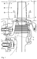
- Ein Ausführungsbeispiel der Erfindung wird anhand der Zeichnung näher erläutert. Es zeigen:
- Fig. 1
- eine Seitenansicht einer aus einem Schaufelblatt und einer Schaufelplattform bestehenden, lin einem Turbinengehäuse angeordneten Turbinenlaufschaufel, deren Schaufelfuß in einer Rotorscheibe gehalten ist;
- Fig. 2
- einen Schnitt AA der Turbinenlaufschaufel nach Fig. 1; und
- Fig. 3
- eine detaillierte Darstellung der mit Kühlluft abgedichteten Seitenfläche der Schaufelplattform in dem mechanisch nicht abgedichteten Bereich.
- Am Umfang einer Rotorscheibe 1 ist in Quernuten (nicht dargestellt) eine Mehrzahl Turbinenlaufschaufeln - jeweils über deren Schaufelfuß 2 - lösbar angebracht. Über in der Rotorscheibe 1 ausgebildete Kühlluftbohrungen 3, an die sich Bohrungen (nicht dargestellt) im Schaufelfuß 2 anschließen, gelangt vom Verdichter abgezweigte Kühlluft (Pfeil A) in die in dem jeweiligen Schaufelblatt 4 ausgebildeten Hohlräume 5. Auf diese Weise wird das dem Heißgasstrom (Pfeil B) ausgesetzte Schaufelblatt 4 durch eine Innenkühlung und eine Filmkühlung gekühlt. In einem mittleren Bereich der Seitenflächen 6 der Plattformen 7 der Turbinenlaufschaufeln sind Ausnehmungen 8 zur Aufnahme eines Dichtungs- und Dämpfungselements (nicht dargestellt) ausgebildet. Die jeweils zwischen den gegenüberliegenden Seitenflächen 6 benachbarter Schaufelplattformen 7 angeordneten Dichtungs- und Dämpfungselemente sollen einerseits die Vibration der Laufschaufeln und andererseits den Kontakt der Turbinenscheibe mit dem Heißgas begrenzen. Die Anordnung des Dichtungs- und Dämpfungselements ist aufgrund der konstruktiven Ausbildung der Schaufelplattformen 7 und aus fertigungstechnischen Gründen auf einen bestimmten - geraden - Bereich der jeweiligen Seitenfläche beschränkt. Der verbleibende freie Spalt zwischen den Seitenflächen 6 der Schaufelplattformen 7 wird mit einem kontinuierlichen Dichtungsluftstrom (Pfeil C), der aus einem Hohlraum 5 des Schaufelblattes 4 zugeführt wird, gegenüber der Heißgasatmosphäre abgeschirmt. Die Dichtungsluftzufuhr erfolgt über einen Luftkanal 9, der unmittelbar an einer Seitenfläche der Plattformen mündet, und zwar in einem unter Heißgaseinfluss stehenden Spaltbereich, der nicht mechanisch durch ein Dichtungs- und Dämpfungselement abgedichtet ist. In dem vorliegenden Ausführungsbeispiel ist der Luftzutritt axial getrennt von dem mechanischen Dichtungs- und Dämpfungselement vorgesehen. Die Dichtungsluftaustrittsöffnung kann aber auch in Verbindung mit dem Dichtungs- und Dämpfungselement so angeordnet sein, dass dessen Dichtwirkung verstärkt wird.
- In der hier beschriebenen Ausführungsform ist ein einziger Luftkanal 9 mit rundem Querschnitt vorgesehen. Es können aber auch zwei oder auch mehrere Luftkanäle angeordnet sein, die zudem eine beliebige Querschnittform aufweisen können und auch zu beiden Seitenflächen 6 ein und derselben Schaufelplattform 7 führen können.
- Die zwischen den Seitenflächen 6 jeweils benachbarter Plattformen 7 eintretende Dichtungsluft verteilt sich in dem Spalt und dichtet diesen gegenüber der Heißluft ab.
- Zumindest wird aber gegebenenfalls in den Spalt eintretende Heißluft durch die kältere Dichtungsluft abgekühlt. Auf diese Weise wird der Zutritt von Heißgas in den Bereich unterhalb der Plattformen verhindert oder zumindest reduziert, so dass die Befestigung der Turbinenlaufschaufel an der Rotorscheibe und der Umfangsrand der Rotorscheibe 1 nicht überhitzt und dadurch deren Lebensdauer nicht verringert wird. Auf zusätzliche mechanische Dichtelemente, deren Fertigung und Halterung im Randbereich der Schaufelplattformen mit einem erheblichen Aufwand verbunden ist, kann verzichtet werden.
- Wie die Zeichnung, insbesondere Fig. 3, zeigt, kann der Luftkanal 9 auch in eine in die Seitenfläche 6 der Plattform 7 eingeformte Verteilungsnut 10 münden, um so die Dichtungsluft gezielt in dem Spalt zwischen den gegenüberliegenden Seitenflächen 6 zu verteilen. Die Verteilungsnuten 10 können eine beliebige Form haben. Es können in einer Seitenfläche auch mehrere Verteilungsnuten ausgebildet sein.
-
- 1
- Rotorscheibe
- 2
- Schaufelfuß
- 3
- Kühlluftbohrung
- 4
- Schaufelblatt
- 5
- Hohlraum in 4
- 6
- Seitenfläche v. 7
- 7
- Schaufelplattform
- 8
- Ausnehmung
- 9
- Luftkanal
- 10
- Verteilungsnut
- Pfeil A
- Kühlluft v. Verdichter
- Pfeil B
- Heißgasstrom
- Pfeil C
- Dichtungsluftstrom
Claims (4)
- Gasturbinenrotor, der eine Rotorscheibe (1) mit an deren Umfangsrand in Quernuten gehaltenen Turbinenlaufschaufeln, die aus einem Schaufelblatt (4), einer Schaufelplattform (7) und einem in der jeweiligen Quernut fixierten Schaufelfuß (2) bestehen, umfasst, wobei die Schaufelblätter (4) von Kühlluft durchströmte Hohlräume (5) aufweisen und in den einander gegenüberliegenden Seitenflächen (6) der Schaufelplattformen (7) jeweils eine Ausnehmung (8) zur Aufnahme eines den Spalt zwischen den Schaufelplattformen (7) überbrückenden Dichtungs- und Dämpfungselements ausgebildet ist, gekennzeichnet durch mindestens einen mit dem Hohlraum (5) in dem Schaufelblatt (4) verbundenen Luftkanal (9), der zur zusätzlichen aerodynamischen Abdichtung des Spaltes mit einem Luftvolumen zwischen den Schaufelplattformen (7) an mindestens einer von deren Seitenflächen (6)) mündet.
- Gasturbinenrotor nach Anspruch 1, dadurch gekennzeichnet, dass der Luftkanal (9) in eine in die Seitenfläche (6) der Schaufelplattform (7) eingeformte Luftverteilungsnut (10) mündet.
- Gasturbinenrotor nach Anspruch 1 oder 2, dadurch gekennzeichnet, dass der Luftkanal (9) und/oder die Luftverteilungsnut (10) so angeordnet sind, das die Dichtungsluftzufuhr axial getrennt von dem Dichtungs- und Dämpfungselement erfolgt.
- Gasturbinenrotor nach Anspruch 1 oder 2, dadurch gekennzeichnet, dass der Luftkanal (9)und/oder die Luftverteilungsnut (10) so angeordnet sind, dass die Dichtungsluftzufuhr auch im Bereich des Dichtungs- und Dämpfungselements erfolgt.
Applications Claiming Priority (1)
| Application Number | Priority Date | Filing Date | Title |
|---|---|---|---|
| DE102004037331A DE102004037331A1 (de) | 2004-07-28 | 2004-07-28 | Gasturbinenrotor |
Publications (3)
| Publication Number | Publication Date |
|---|---|
| EP1621735A2 true EP1621735A2 (de) | 2006-02-01 |
| EP1621735A3 EP1621735A3 (de) | 2008-12-17 |
| EP1621735B1 EP1621735B1 (de) | 2010-02-24 |
Family
ID=34981327
Family Applications (1)
| Application Number | Title | Priority Date | Filing Date |
|---|---|---|---|
| EP05106088A Ceased EP1621735B1 (de) | 2004-07-28 | 2005-07-05 | Gasturbinenrotor |
Country Status (3)
| Country | Link |
|---|---|
| US (1) | US7874803B2 (de) |
| EP (1) | EP1621735B1 (de) |
| DE (2) | DE102004037331A1 (de) |
Cited By (1)
| Publication number | Priority date | Publication date | Assignee | Title |
|---|---|---|---|---|
| EP2372090B1 (de) * | 2010-03-22 | 2019-05-22 | General Electric Company | Vorrichtung zum Kühlen einer Schaufelanordnung |
Families Citing this family (5)
| Publication number | Priority date | Publication date | Assignee | Title |
|---|---|---|---|---|
| KR101232609B1 (ko) * | 2010-12-21 | 2013-02-13 | 두산중공업 주식회사 | 가스터빈 엔진의 로터 블레이드 프리 스월 냉각 장치 |
| US11021976B2 (en) * | 2014-12-22 | 2021-06-01 | Raytheon Technologies Corporation | Hardware geometry for increasing part overlap and maintaining clearance |
| US10030582B2 (en) | 2015-02-09 | 2018-07-24 | United Technologies Corporation | Orientation feature for swirler tube |
| JP5905631B1 (ja) * | 2015-09-15 | 2016-04-20 | 三菱日立パワーシステムズ株式会社 | 動翼、これを備えているガスタービン、及び動翼の製造方法 |
| US10655489B2 (en) | 2018-01-04 | 2020-05-19 | General Electric Company | Systems and methods for assembling flow path components |
Citations (2)
| Publication number | Priority date | Publication date | Assignee | Title |
|---|---|---|---|---|
| EP0940561A1 (de) | 1998-03-03 | 1999-09-08 | Mitsubishi Heavy Industries, Ltd. | Laufradschaufelplatte einer Gasturbine |
| US6561764B1 (en) | 1999-03-19 | 2003-05-13 | Siemens Aktiengesellschaft | Gas turbine rotor with an internally cooled gas turbine blade and connecting configuration including an insert strip bridging adjacent blade platforms |
Family Cites Families (19)
| Publication number | Priority date | Publication date | Assignee | Title |
|---|---|---|---|---|
| DE1822762U (de) | 1959-07-31 | 1960-12-01 | Entwicklungsbau Pirna Veb | Hydrodynamische dichtung fuer schnell umlaufende wellen. |
| BE621931A (de) | 1961-08-30 | |||
| GB1284596A (en) | 1969-12-20 | 1972-08-09 | Rolls Royce | Improvements in or relating to hydraulic seals |
| US4101245A (en) * | 1976-12-27 | 1978-07-18 | United Technologies Corporation | Interblade damper and seal for turbomachinery rotor |
| GB2125118A (en) | 1982-08-03 | 1984-02-29 | Rolls Royce | Hydraulic seal |
| JP3040660B2 (ja) * | 1994-06-06 | 2000-05-15 | 三菱重工業株式会社 | ガスタービン動翼プラットフォームの冷却機構 |
| ES2118638T3 (es) * | 1994-10-31 | 1998-09-16 | Westinghouse Electric Corp | Alabe rotativo de turbina de gas con plataforma refrigerada. |
| FR2758855B1 (fr) * | 1997-01-30 | 1999-02-26 | Snecma | Systeme de ventilation des plates-formes des aubes mobiles |
| JP3462695B2 (ja) * | 1997-03-12 | 2003-11-05 | 三菱重工業株式会社 | ガスタービン動翼シール板 |
| DE59710924D1 (de) * | 1997-09-15 | 2003-12-04 | Alstom Switzerland Ltd | Kühlvorrichtung für Gasturbinenkomponenten |
| GB9801561D0 (en) * | 1998-01-27 | 1998-03-25 | Rolls Royce Plc | Hydraulic seal |
| CA2262064C (en) * | 1998-02-23 | 2002-09-03 | Mitsubishi Heavy Industries, Ltd. | Gas turbine moving blade platform |
| DE19916803A1 (de) * | 1999-04-14 | 2000-10-19 | Rolls Royce Deutschland | Hydraulische Dichtungsanordnung insbesondere an einer Gasturbine |
| US6241467B1 (en) * | 1999-08-02 | 2001-06-05 | United Technologies Corporation | Stator vane for a rotary machine |
| US6254333B1 (en) * | 1999-08-02 | 2001-07-03 | United Technologies Corporation | Method for forming a cooling passage and for cooling a turbine section of a rotary machine |
| US6402471B1 (en) * | 2000-11-03 | 2002-06-11 | General Electric Company | Turbine blade for gas turbine engine and method of cooling same |
| DE10064265A1 (de) * | 2000-12-22 | 2002-07-04 | Alstom Switzerland Ltd | Vorrichtung und Verfahren zur Kühlung einer Plattform einer Turbinenschaufel |
| JP2002201913A (ja) * | 2001-01-09 | 2002-07-19 | Mitsubishi Heavy Ind Ltd | ガスタービンの分割壁およびシュラウド |
| US6945749B2 (en) * | 2003-09-12 | 2005-09-20 | Siemens Westinghouse Power Corporation | Turbine blade platform cooling system |
-
2004
- 2004-07-28 DE DE102004037331A patent/DE102004037331A1/de not_active Withdrawn
-
2005
- 2005-07-05 DE DE502005009070T patent/DE502005009070D1/de not_active Expired - Lifetime
- 2005-07-05 EP EP05106088A patent/EP1621735B1/de not_active Ceased
- 2005-07-27 US US11/189,771 patent/US7874803B2/en not_active Expired - Fee Related
Patent Citations (2)
| Publication number | Priority date | Publication date | Assignee | Title |
|---|---|---|---|---|
| EP0940561A1 (de) | 1998-03-03 | 1999-09-08 | Mitsubishi Heavy Industries, Ltd. | Laufradschaufelplatte einer Gasturbine |
| US6561764B1 (en) | 1999-03-19 | 2003-05-13 | Siemens Aktiengesellschaft | Gas turbine rotor with an internally cooled gas turbine blade and connecting configuration including an insert strip bridging adjacent blade platforms |
Cited By (1)
| Publication number | Priority date | Publication date | Assignee | Title |
|---|---|---|---|---|
| EP2372090B1 (de) * | 2010-03-22 | 2019-05-22 | General Electric Company | Vorrichtung zum Kühlen einer Schaufelanordnung |
Also Published As
| Publication number | Publication date |
|---|---|
| EP1621735B1 (de) | 2010-02-24 |
| US20060024166A1 (en) | 2006-02-02 |
| US7874803B2 (en) | 2011-01-25 |
| DE102004037331A1 (de) | 2006-03-23 |
| DE502005009070D1 (de) | 2010-04-08 |
| EP1621735A3 (de) | 2008-12-17 |
Similar Documents
| Publication | Publication Date | Title |
|---|---|---|
| DE102009003327B4 (de) | Turbinenlaufschaufel-Spitzendeckband | |
| DE102004054294B4 (de) | Kühlsystem für Plattformkanten von Leitradsegmenten | |
| EP1740797B1 (de) | Gasturbine | |
| DE602005000350T2 (de) | Turbinenstatorschaufel mit verbesserter Kühlung | |
| EP1496203B1 (de) | Turbinenschaufel mit Prallkühlung | |
| EP2414640B1 (de) | Schaufel für eine gasturbine | |
| DE102008055590B4 (de) | Turbinenschaufel-Deckband | |
| DE102006004437A1 (de) | Plattform einer Laufschaufel einer Gasturbine, Verfahren zur Herstellung einer Laufschaufel, Dichtungsplatte und Gasturbine | |
| WO2003052240A2 (de) | Gasturbinenanordnung | |
| CH698339B1 (de) | Turbinenschaufel mit gekühltem Deckband. | |
| DE102010016620A1 (de) | Turbinenleitapparat mit Seitenwandkühlplenum | |
| DE19904229A1 (de) | Gekühlte Turbinenschaufel | |
| DE2241194B2 (de) | Strömungsmaschinenschaufel mit inneren Kühlkanälen | |
| WO2009118245A1 (de) | Leitschaufel für eine gasturbine sowie gasturbine mit einer solchen leitschaufel | |
| EP1745195B1 (de) | Strömungsmaschinenschaufel | |
| EP1496199B1 (de) | Gekühltes Hochdruckturbinenlaufrad für ein Flugtriebwerk | |
| EP1073827B1 (de) | Turbinenschaufel | |
| DE602004010557T2 (de) | Ringförmige Leitschaufelplattform einer Niederdruckstufe einer Gasturbine | |
| DE102009003328A1 (de) | Turbinenlaufschaufel-Spitzendeckband | |
| DE69925447T2 (de) | Kühlbare Schaufelblätter | |
| EP1621735B1 (de) | Gasturbinenrotor | |
| DE602004006035T2 (de) | Kühleinrichtung für Turbinenscheiben | |
| EP2626644B1 (de) | Lüftungsbauteil, umfassend ein kanalförmiges Gehäuse mit umlaufend angeordneten Gehäusewandungen | |
| DE19940556B4 (de) | Vorrichtung zum Kühlen von Leit- oder Laufschaufeln in einer Gasturbine | |
| DE10306915A1 (de) | Dichtungsanordnung, insbesondere für Gasturbinen |
Legal Events
| Date | Code | Title | Description |
|---|---|---|---|
| PUAI | Public reference made under article 153(3) epc to a published international application that has entered the european phase |
Free format text: ORIGINAL CODE: 0009012 |
|
| AK | Designated contracting states |
Kind code of ref document: A2 Designated state(s): AT BE BG CH CY CZ DE DK EE ES FI FR GB GR HU IE IS IT LI LT LU LV MC NL PL PT RO SE SI SK TR |
|
| AX | Request for extension of the european patent |
Extension state: AL BA HR MK YU |
|
| PUAL | Search report despatched |
Free format text: ORIGINAL CODE: 0009013 |
|
| AK | Designated contracting states |
Kind code of ref document: A3 Designated state(s): AT BE BG CH CY CZ DE DK EE ES FI FR GB GR HU IE IS IT LI LT LU LV MC NL PL PT RO SE SI SK TR |
|
| AX | Request for extension of the european patent |
Extension state: AL BA HR MK YU |
|
| 17P | Request for examination filed |
Effective date: 20090205 |
|
| AKX | Designation fees paid |
Designated state(s): DE FR GB |
|
| GRAP | Despatch of communication of intention to grant a patent |
Free format text: ORIGINAL CODE: EPIDOSNIGR1 |
|
| GRAS | Grant fee paid |
Free format text: ORIGINAL CODE: EPIDOSNIGR3 |
|
| GRAA | (expected) grant |
Free format text: ORIGINAL CODE: 0009210 |
|
| AK | Designated contracting states |
Kind code of ref document: B1 Designated state(s): DE FR GB |
|
| REG | Reference to a national code |
Ref country code: GB Ref legal event code: FG4D Free format text: NOT ENGLISH |
|
| REF | Corresponds to: |
Ref document number: 502005009070 Country of ref document: DE Date of ref document: 20100408 Kind code of ref document: P |
|
| PLBE | No opposition filed within time limit |
Free format text: ORIGINAL CODE: 0009261 |
|
| STAA | Information on the status of an ep patent application or granted ep patent |
Free format text: STATUS: NO OPPOSITION FILED WITHIN TIME LIMIT |
|
| 26N | No opposition filed |
Effective date: 20101125 |
|
| REG | Reference to a national code |
Ref country code: DE Ref legal event code: R082 Ref document number: 502005009070 Country of ref document: DE |
|
| REG | Reference to a national code |
Ref country code: FR Ref legal event code: PLFP Year of fee payment: 12 |
|
| REG | Reference to a national code |
Ref country code: FR Ref legal event code: PLFP Year of fee payment: 13 |
|
| REG | Reference to a national code |
Ref country code: FR Ref legal event code: PLFP Year of fee payment: 14 |
|
| PGFP | Annual fee paid to national office [announced via postgrant information from national office to epo] |
Ref country code: FR Payment date: 20190725 Year of fee payment: 15 Ref country code: DE Payment date: 20190729 Year of fee payment: 15 |
|
| PGFP | Annual fee paid to national office [announced via postgrant information from national office to epo] |
Ref country code: GB Payment date: 20190729 Year of fee payment: 15 |
|
| REG | Reference to a national code |
Ref country code: DE Ref legal event code: R119 Ref document number: 502005009070 Country of ref document: DE |
|
| GBPC | Gb: european patent ceased through non-payment of renewal fee |
Effective date: 20200705 |
|
| PG25 | Lapsed in a contracting state [announced via postgrant information from national office to epo] |
Ref country code: GB Free format text: LAPSE BECAUSE OF NON-PAYMENT OF DUE FEES Effective date: 20200705 Ref country code: FR Free format text: LAPSE BECAUSE OF NON-PAYMENT OF DUE FEES Effective date: 20200731 |
|
| PG25 | Lapsed in a contracting state [announced via postgrant information from national office to epo] |
Ref country code: DE Free format text: LAPSE BECAUSE OF NON-PAYMENT OF DUE FEES Effective date: 20210202 |