EP1620646B1 - Rotorblatt einer windenergieanlage - Google Patents
Rotorblatt einer windenergieanlage Download PDFInfo
- Publication number
- EP1620646B1 EP1620646B1 EP04723988.4A EP04723988A EP1620646B1 EP 1620646 B1 EP1620646 B1 EP 1620646B1 EP 04723988 A EP04723988 A EP 04723988A EP 1620646 B1 EP1620646 B1 EP 1620646B1
- Authority
- EP
- European Patent Office
- Prior art keywords
- rotor blade
- power system
- wind power
- rotor
- wind
- Prior art date
- Legal status (The legal status is an assumption and is not a legal conclusion. Google has not performed a legal analysis and makes no representation as to the accuracy of the status listed.)
- Expired - Lifetime
Links
- 238000009434 installation Methods 0.000 claims description 12
- 238000005192 partition Methods 0.000 claims 2
- 230000002829 reductive effect Effects 0.000 description 14
- 238000013461 design Methods 0.000 description 10
- 238000004804 winding Methods 0.000 description 10
- 230000007423 decrease Effects 0.000 description 6
- 230000000694 effects Effects 0.000 description 5
- 210000002435 tendon Anatomy 0.000 description 5
- 238000010276 construction Methods 0.000 description 3
- 238000011161 development Methods 0.000 description 3
- 230000018109 developmental process Effects 0.000 description 3
- 238000000926 separation method Methods 0.000 description 3
- 238000004026 adhesive bonding Methods 0.000 description 2
- 238000005253 cladding Methods 0.000 description 2
- 230000006835 compression Effects 0.000 description 2
- 238000007906 compression Methods 0.000 description 2
- 230000000717 retained effect Effects 0.000 description 2
- UJCHIZDEQZMODR-BYPYZUCNSA-N (2r)-2-acetamido-3-sulfanylpropanamide Chemical compound CC(=O)N[C@@H](CS)C(N)=O UJCHIZDEQZMODR-BYPYZUCNSA-N 0.000 description 1
- 241001669680 Dormitator maculatus Species 0.000 description 1
- 230000015572 biosynthetic process Effects 0.000 description 1
- 230000000295 complement effect Effects 0.000 description 1
- 230000003247 decreasing effect Effects 0.000 description 1
- 230000001419 dependent effect Effects 0.000 description 1
- 238000006073 displacement reaction Methods 0.000 description 1
- 238000009826 distribution Methods 0.000 description 1
- 238000011156 evaluation Methods 0.000 description 1
- 230000002349 favourable effect Effects 0.000 description 1
- 238000003306 harvesting Methods 0.000 description 1
- 238000005259 measurement Methods 0.000 description 1
- 230000002093 peripheral effect Effects 0.000 description 1
- 230000001105 regulatory effect Effects 0.000 description 1
- 230000002441 reversible effect Effects 0.000 description 1
- 230000003068 static effect Effects 0.000 description 1
- 238000012546 transfer Methods 0.000 description 1
- 238000009827 uniform distribution Methods 0.000 description 1
Images


Classifications
-
- F—MECHANICAL ENGINEERING; LIGHTING; HEATING; WEAPONS; BLASTING
- F03—MACHINES OR ENGINES FOR LIQUIDS; WIND, SPRING, OR WEIGHT MOTORS; PRODUCING MECHANICAL POWER OR A REACTIVE PROPULSIVE THRUST, NOT OTHERWISE PROVIDED FOR
- F03D—WIND MOTORS
- F03D1/00—Wind motors with rotation axis substantially parallel to the air flow entering the rotor
- F03D1/06—Rotors
- F03D1/0608—Rotors characterised by their aerodynamic shape
- F03D1/0633—Rotors characterised by their aerodynamic shape of the blades
- F03D1/0641—Rotors characterised by their aerodynamic shape of the blades of the section profile of the blades, i.e. aerofoil profile
-
- F—MECHANICAL ENGINEERING; LIGHTING; HEATING; WEAPONS; BLASTING
- F03—MACHINES OR ENGINES FOR LIQUIDS; WIND, SPRING, OR WEIGHT MOTORS; PRODUCING MECHANICAL POWER OR A REACTIVE PROPULSIVE THRUST, NOT OTHERWISE PROVIDED FOR
- F03D—WIND MOTORS
- F03D1/00—Wind motors with rotation axis substantially parallel to the air flow entering the rotor
- F03D1/06—Rotors
- F03D1/065—Rotors characterised by their construction elements
- F03D1/0675—Rotors characterised by their construction elements of the blades
-
- F—MECHANICAL ENGINEERING; LIGHTING; HEATING; WEAPONS; BLASTING
- F05—INDEXING SCHEMES RELATING TO ENGINES OR PUMPS IN VARIOUS SUBCLASSES OF CLASSES F01-F04
- F05B—INDEXING SCHEME RELATING TO WIND, SPRING, WEIGHT, INERTIA OR LIKE MOTORS, TO MACHINES OR ENGINES FOR LIQUIDS COVERED BY SUBCLASSES F03B, F03D AND F03G
- F05B2240/00—Components
- F05B2240/20—Rotors
- F05B2240/30—Characteristics of rotor blades, i.e. of any element transforming dynamic fluid energy to or from rotational energy and being attached to a rotor
- F05B2240/31—Characteristics of rotor blades, i.e. of any element transforming dynamic fluid energy to or from rotational energy and being attached to a rotor of changeable form or shape
- F05B2240/311—Characteristics of rotor blades, i.e. of any element transforming dynamic fluid energy to or from rotational energy and being attached to a rotor of changeable form or shape flexible or elastic
-
- Y—GENERAL TAGGING OF NEW TECHNOLOGICAL DEVELOPMENTS; GENERAL TAGGING OF CROSS-SECTIONAL TECHNOLOGIES SPANNING OVER SEVERAL SECTIONS OF THE IPC; TECHNICAL SUBJECTS COVERED BY FORMER USPC CROSS-REFERENCE ART COLLECTIONS [XRACs] AND DIGESTS
- Y02—TECHNOLOGIES OR APPLICATIONS FOR MITIGATION OR ADAPTATION AGAINST CLIMATE CHANGE
- Y02E—REDUCTION OF GREENHOUSE GAS [GHG] EMISSIONS, RELATED TO ENERGY GENERATION, TRANSMISSION OR DISTRIBUTION
- Y02E10/00—Energy generation through renewable energy sources
- Y02E10/70—Wind energy
- Y02E10/72—Wind turbines with rotation axis in wind direction
Definitions
- the invention relates to a rotor blade of a wind energy installation and a wind energy installation.
- the nose radius and the profile coordinates of the top and bottom are used to describe the cross section of the rotor blade.
- the nomenclature known from the book Erich Hau is to be retained, inter alia, for the further description of the cross section of a rotor blade for the present application.
- Rotor blades can be optimized based on a variety of aspects. On the one hand, they should be quiet, on the other hand, they should also provide maximum dynamic performance, so that the wind turbine can be used when the wind is quite light starts to run and the nominal wind speed is already reached with the lowest possible wind strengths, i.e. the speed at which the nominal power of the wind turbine is also achieved for the first time. If the wind speed then continues to increase, nowadays in pitch-regulated wind turbines the rotor blade is placed more and more in the wind, so that the nominal power is retained, but the surface area of the rotor blade exposed to the wind decreases, in order to prevent the entire wind turbine or its parts from becoming mechanical Protect damage. It is crucial, however, that the aerodynamic properties of the rotor blade profiles of the rotor blade of a wind turbine are of great importance.
- the object of the present invention is to provide a rotor blade with a rotor blade profile or a wind power plant which has a better performance than before.
- the object is achieved with a rotor blade with a rotor blade profile with the features according to the independent claim.
- the rotor blade profile described according to the present application is in particular formed in the area of the rotor blade that connects to the rotor blade connection (for connection to the hub).
- the profile described in the present application is preferably formed in the first third of the rotor blade, based on the total length of the rotor blade.
- the total length of a rotor blade can be in the range of 10 m to 70 m, depending on the nominal power that a wind turbine should have.
- the rated power of a wind turbine from Enercon of the E-112 type is 4.5 MW
- the rated power of a wind turbine from Enercon of the E-30 type is 300 KW.
- the greatest profile thickness is approximately 25% to 40%, preferably 32% to 36%, of the length of the rotor blade chord.
- the greatest profile thickness is about 34.6% of the length of the rotor blade chord.
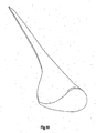
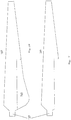
- a chord 1 is entered, which extends from the center 2 of the rotor blade trailing edge 3 to the foremost point 4 of the rotor blade nose 5.
- the thickness reserve ie the location based on the blade length, where the greatest profile thickness is formed, is approximately 20% to 30% of the length of the chord, preferably 23% to 28%, in the example shown 25.9%. The greatest thickness was determined perpendicular to the tendon and the reserve is related to the rotor blade nose.
- a so-called skeleton line 7 is entered.
- This skeleton line results from the respective half thickness of the rotor blade 8 on one Point. Accordingly, this skeleton line does not run in a straight line, but always exactly between opposite points on the pressure side 9 of the rotor blade 7 and the suction side 10 of the rotor blade 7.
- the skeleton line cuts the chord at the rear edge of the rotor blade and the rotor blade nose.
- the curvature reserve in the cross section of a rotor blade according to the invention is approximately 55% to 70% of the length of the chord, preferably approximately 59% to 63%.
- the bulge reserve is approximately 61.9% of the length of the tendon.
- the greatest curvature is about 4% to 8% of the length of the tendon, preferably about 5% to 7% of the length of the tendon. In the example shown, the curvature is approximately 5.87% of the length of the tendon.
- the pressure side of the rotor blade "cuts" the chord twice, that is to say the pressure side of the profile is concave in this region, while in the front profile region the pressure side is convex. In the area where the pressure side is concave, the corresponding, opposite area on the suction side is almost straight-lined.
- the trailing edge of the rotor blade of the profile shown is also strikingly thick. However, this is not problematic with regard to the formation of sound at the rear edge of the rotor blade, because the profile shown is located in the inner third of the rotor circle and the path speed is not very high there.
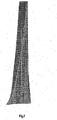
- the rotor blade To improve the aerodynamic shape of the rotor blade, it is designed in the area of the rotor blade root in such a way that it has its greatest width there and thus the rotor blade has a trapezoidal shape that is more or less approximated to the aerodynamic optimum shape (in the view).
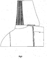
- the rotor blade is preferably designed in the region of the rotor blade root in such a way that the edge of the rotor blade root facing the gondola of a wind energy installation is adapted to the outer contour of the gondola in at least one angular position, e.g. B.
- a wind power installation according to the invention achieves a higher output at a given wind speed below the nominal wind speed. In addition, it reaches its nominal output earlier than before. Accordingly, the rotor blades can also be rotated (pitched) earlier, reducing the noise emission on the one hand and the mechanical load on the system on the other.
- the invention is based on the finding that the current rotor blade shape in the wind tunnel is examined at different wind speeds, but always with a uniform air flow.
- the known rotor blades due to gusts, cause the flow to separate, especially in the blade interior near the rotor hub, where the blade no longer is aerodynamically clean and optimally designed.
- This flow separation continues in the direction of the rotor blade outer region (rotor blade tip) along the rotor blade.
- the flow from the rotor blade can separate from the rotor blade in a bubble-shaped region and thus lead to corresponding losses in performance.
- a well-designed rotor blade can also achieve a significant increase in performance in the interior of the rotor blade.
- the reality is different.
- the wind does not blow evenly and statically within a certain area, but rather clearly shows a stochastic behavior
- the influence of the wind speed is considerable and the angle of attack in this area changes with a high dependence on the current wind speed.
- the flow from the rotor blade is accordingly also frequently detached in the inner region of the rotor blade.
- the design of the rotor blade according to the invention significantly reduces the risk of flow separation. This risk of detachment is also reduced by the relatively thick profile.
- the considerable increase in performance can also be explained well by the fact that the hysteresis effect in the event of a separation of the flow once occurring means that the performance losses are maintained over a considerable period of time (for rotor blades according to the prior art).
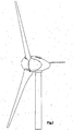
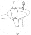
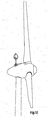
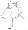
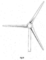
- Figures 11 to 17 show the view of a wind turbine according to the invention from the front or from the side. Here you can see how the three rotor blades in the area near the hub merge almost seamlessly into the outer design of the nacelle. However, this only applies to the position of the rotor blades insofar as they are in the nominal wind position.
- Figure 15 shows that there is definitely a greater distance between the lower edge of the rotor blade in the interior and the nacelle.
- Figure 4 but also shows that a structure is formed on the outside of the nacelle whose cross-section largely corresponds to the profile of the rotor blade in the area near the hub and when the rotor blade is positioned at an angle of attack at nominal speed directly below the rotor blade, so that only a small gap is formed between the structure and the rotor blade in the area near the hub.
- the outer contour of the nacelle therefore also contains a part of the rotor blade which is not an integral part of the rotor blade.
- the nose radius is about 0.146 of the profile depth.
- the maximum deviation from the ideal straight line is approximately 0.012 of the profile length. This value is the decisive value since the radius of curvature varies and the largest radius of curvature is already specified in the respective areas.
- the length of the suction side is approximately 1.124 the length of the profile depth
- the length of the pressure side is 1.112 the length of the profile depth. This means that the suction side is only slightly longer than the pressure side. It is therefore very advantageous if the ratio of the suction side length to the pressure side length is less than 1.2, preferably less than 1.1 or in a range of values between 1 and 1.03.
- the rotor blade has its greatest profile depth directly on the spinner, that is to say on the outside of the nacelle of the wind turbine.
- the profile depth on the spinner can be approximately 1.8 to 1.9, preferably 1.84 m.
- the ratio of the profile depth of the rotor blade on the spinner to the spinner diameter is approximately 0.575. It is therefore very advantageous if the ratio of the profile depth to the spinner diameter is greater than a value of 0.4 or in a range of values between 0.5 and 1. Any value from the aforementioned range of values can be accepted.
- the ratio of the profile depth is to the rotor diameter about 0.061. It is obvious that the "loophole" is therefore as small as possible if the ratio of the profile depth to the rotor diameter is greater than a value of 0.05 to 0.01, the exemplary value proving to be extremely favorable, which the Performance of the rotor blade concerned.
- Another example is a rotor blade with the Figure 18 Profile cross section shown in the first third, the profile depth on the spinner is about 4.35 m, the spinner diameter is 5.4 m and the rotor diameter is a total of 71 m. Then the value of the profile depth to the spinner diameter is 0.806 and the ratio of the profile depth to the rotor diameter is again 0.061.
- the above values refer to a three-blade rotor with pitch control.
- the widest point (the point with the greatest profile depth) of the rotor blade can be formed directly in the area of the blade connection.
- the blade connection is the area in which the rotor blade is connected (connected, screwed, etc.) to the hub of the wind turbine.
- the lower edge of the rotor blade that is to say the edge which faces the nacelle of the wind energy installation, largely follows or adjusts the outer contour of the nacelle in the longitudinal direction.
- a rotor blade when a rotor blade is in the flag position (practically no wind-oriented surface), it lies parallel to the lower edge facing the nacelle and the distance between the lower edge and the outer contour of the nacelle is minimal, preferably less than 50 cm or better still less than 20 cm.
- the rotor blade width is very large. So that a transport of such rotor blades is still possible (the width of the rotor blade in the area near the hub can be 5 m to 8 m for large rotor blades, i.e. rotor blades that are longer than 30 m, can be 5 m to 8 m), while during the Transport both parts are separate and can be assembled after transport. For this purpose, both parts of the installation on the wind turbine are connected to one another, for example via screw connections and permanent connections (gluing).
- the efficiency can be significantly increased compared to previous rotor blades.
- the rotor blades are designed such that they have their greatest profile depth in the area near the hub and, in addition, the rotor blades have moved very close to the nacelle cover (spinner) of the nacelle of the wind power installation along their entire profile in the area near the hub. At least for the position at which the rotor blade assumes an angle which is assumed at wind speeds up to the nominal wind range, this results in a very small distance from the nacelle cladding. While in the presentation such as after Figure 1 .
- Figure 18 shows the cross section of a rotor blade according to the invention along the line A - A in Figure 17 , i.e. the profile of the rotor blade in the area near the hub.
- Figure 17 also contains an indication of what is meant by the diameter D of the spinner.
- the rotor diameter is described by the diameter of the circular area that is swept by the rotor when it rotates.
- the part 30 of the rotor blade which is not an integral part of the rotatable rotor blade, is an integral part of the outer lining of the nacelle.
- the respective part can be screwed onto the gondola or can also be connected or glued in one piece to the gondola.
- the rotor blade according to the present application has a large length and a corresponding rotor blade depth, i.e. a long blade chord, in the area near the hub, it may be advantageous for transport reasons to make the blade in this area in two parts (or in several parts) and one Reassemble the rear blade area only at the construction site, where the entire rotor blade is placed on the hub.
- part of the rotor blade can be designed as shown in FIG Fig. 20 is shown. It can be seen there that a piece is missing in the sheet trailing edge area. If the missing piece is applied, the result in this area is again in Fig. 18 shown profile.
- the two parts can be fastened together by screwing, gluing or other types of fastening.
- part of the surface is formed from a deformable material which is part of a closed container (which forms the rear profile box).
- This closed container can, for example, be filled with a gaseous medium, a presettable pressure being applied to this gaseous medium.
- the effective surface of the rotor blade and thus the area of attack for the wind become smaller.
- the load on the subsequent components including the tower decreases.
- the rotor blade in the rear box area (which in Figure 20 not shown) has a second and / or in itself movable second support structure.
- the deformable material can be fastened at predetermined points of this second support structure and the deformable material can also be fastened on one side to a rotatable winding core.
- the second supporting structure can now be extended, i.e. that is, folding arms can be fully extended or telescopic arms fully extended.
- the deformable material can be attached on one side to a rotatable winding core. If the rotor blade area is now to be reduced, the winding core is rotated so that it winds up the deformable material, analogously to an awning.
- the folding arms are folded and reduce the size of the second supporting structure in the area of the surface that can be reduced, so that the surface of the rotor blade is reduced accordingly.
- part of the surface of the rotor blade consists of lamella-like strips which are each arranged on a support rail which can be pivoted about its own longitudinal axis. In normal operation, these fins are aligned so that they increase the aerodynamically effective surface of the rotor blade.
- the mounting rails can be swiveled so that these slats e.g. get into the slipstream of the remaining rotor blade and thereby the surface of the rotor blade is reduced.
- a movable part of the aerodynamically effective surface of the rotor blade consists of a single surface element which can be displaced in the direction of the depth of the rotor blade. In normal operation, this surface element extends the surface of the rotor blade, preferably on the suction side, in order to create a large, aerodynamically effective surface.
- this surface element comparable to the flap system of an aircraft wing, can be moved such that it is either moved into the rotor blade and thus from the remaining one Surface of the rotor blade is covered, or is moved to the surface of the rotor blade and in turn covers the surface of the rotor blade. In any case, this results in a reduction in the surface area of the rotor blade.
- this surface element can be pivoted on one side to the first support structure or the rear edge of the rotor blade. To change the size of the rotor blade surface, this element can be pivoted around this pivot axis either to the suction side or to the pressure side of the rotor blade.
- a pivoting of this surface element by approximately 90 ° has the effect that this element is essentially perpendicular to the direction of the air flow on the rotor blade and has a corresponding braking effect, since it forms an obstacle for the air flowing along the surface of the rotor blade.
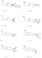
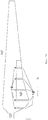
- FIG 20 is a plan view of a complete rotor blade according to the invention is shown in simplified form.
- the rotor blade 100 is divided into two areas. Most of the rotor blade 100 is constructed conventionally. However, a division of the rotor blade can be seen in an area adjacent to the rotor blade root 120, namely the area with the greatest blade depth. This division marks the area of the rotor blade 140, the surface of which can be reduced if necessary and thus removed from the action of the wind.
- FIG 22 shows a simplified cross-sectional representation of a first embodiment of the invention.
- the rotor blade 100 is divided into a front area 110 and a rear box 140.
- This rear box 140 consists of two sheets of deformable material 180, which together with the rear wall of the front area 110 form a closed container 160. If this closed container 160 is now filled with a gaseous medium under pressure, the deformable material 180 forms a part (in Figure 20 identified by reference numeral 140) the surface of the rotor blade 100 according to the invention which is aerodynamically active in normal operation.
- a suitable choice of the filling pressure results in such stability of this part of the rotor blade 100 that it has its normal effect in normal wind conditions.
- the wind pressure on this part of the rotor blade 100 is greater, so that the external pressure is then greater than the internal pressure, and thus the rotor blade is deformed in the region of the rear box 140 and the rotor blade gives the external wind pressure to.
- the area of attack for this extreme wind is smaller and thus the loads on the subsequent construction are smaller.
- this part of the rear box in which the filling medium is accommodated
- This active emptying has the advantage that the shape of the rotor blade is defined at all times, while indefinite situations could occur when the back box gives way due to external pressure.
- a pressure relief valve (not shown) can be provided, through which an excess pressure forming in the container 160 can escape.
- the pressure required for normal operation can be restored. If controllable valves and / or pressure sensors (also not shown) are also provided, the filling pressure in the container 160 can also be tracked in the event of fluctuations in the wind pressure, so as to always maintain optimal operating conditions.
- Figure 23 shows a second embodiment of the present invention, in which instead of a complete rear box 140, the surface of the suction side of the rotor blade 100 is extended.
- This extension is a surface element 240 which adjoins the surface of the front area 110.
- this area element 240 can be moved in the direction of the arrow.
- This shift can e.g. hydraulically, namely with corresponding hydraulic cylinders, pneumatically, with pneumatic cylinders, by electric drives or in another suitable manner.
- Corresponding pumps, compressors or drives (actuators) (of course not shown in the figure for reasons of clarity) must of course be provided for this.
- This shifting can take place into the front area so that the surface of the front area 110 covers the surface element 240.
- the displacement can also take place on the surface of the front area 110, so that the surface element 240 in turn covers the corresponding part of the surface of the front area 110. In both cases, there is a reduction in the aerodynamically effective surface area of the rotor blade 100.
- FIGS Figures 24a and 24b A third embodiment of the present invention is shown in FIGS Figures 24a and 24b shown.
- Figure 24a shows a roll 200 of a deformable material and the reference numeral 300 denotes folding arms which are in the folded state.
- the mechanics can be comparable to that of an awning.
- FIG 24b this embodiment is shown in the state of normal operation.
- the folding arms 300 are stretched, and since the deformable material 180 is attached to it, this was unwound from the winding 200 when the folding arms 300 were extended, so that the winding core 210 no longer carries the entire material winding.
- the deformable material 180 is fastened on the one hand to the winding core 210 and on the other hand to the ends of the folding arms 300 pointing to the right in the figure.
- These ends of the folding arms 300 can in turn be connected by a web, not shown, on the one hand to achieve a higher strength of the construction and on the other hand to fix the deformable material.
- a scissor-lattice-like device (not shown) which is actuated in synchronism with the folding arms 30 and the deformable material 180 can be provided below the deformable material 180 supports in the extended state.
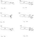
- the surface element 240 is pivotally articulated on the back of the front region 110 and thus extends the suction side of this front region 110.
- the surface element 240 is supported by a compression spring 280, which is arranged between the surface element 240 and the supporting structure of the front area 110.
- this compression spring 280 supports the surface element 240 so that it maintains the desired position. If there is a wind pressure beyond the normal operating conditions on the upper side of the rotor blade 100, the pressure increases on the surface of the surface element 240 and overcomes the force of the spring 280, so that the surface element 240 in the Figure 25 is pressed down, that is to say gives in to the wind pressure, and the aerodynamically effective surface is accordingly reduced accordingly.
- corresponding telescopic elements such as hydraulic or pneumatic devices or mechanical devices for actively adjusting the surface element can of course be formed, e.g. can threaded rods and worm drive or similar. are used to hold the surface element 240 in a first predetermined position or to move it to a second predetermined position.
- corresponding pumps, compressors or drives must of course be provided for the actuation of these actuators, which in turn are not shown in this figure to improve clarity.
- the wind load which acts on the surface element 240 can in turn be detected and, depending on this detected wind load, the surface element 240 can be pivoted around the pivot axis in order to make an optimal setting for the current operating conditions.
- Figure 26 shows a fifth embodiment of the invention.
- the surface element 240 is arranged on the rear of the front region 110 on a pivot axis 220 which can be rotated about its own longitudinal axis.
- the surface element 24 In the in Figure 26 In the position shown, the surface element 24 in turn extends the aerodynamically effective surface of the rotor blade 100.
- the pivot axis 220 with the surface element 240 attached to it is rotated about its longitudinal axis in such a way that the outer end of the surface element 240 is in one of the two moved by the directions shown by the double arrow.
- This leads to a reduction in the aerodynamically effective surface of the rotor blade 100 and, as a result, to a change in the wind load on the rotor blade 100 and all subsequent components of the wind energy installation.
- Figure 26 A variant of the in Figure 26 embodiment shown in the Figures 27a and 27b shown. It is in Figure 26 area element designated by 240 in Figure 27a divided into three lamellar elements 260. These are in Figure 27a deliberately shown at a distance to illustrate this division. In an actual embodiment, these three elements are of course arranged in such a way that they form a surface that is as closed as possible, which in turn connects as smoothly as possible to the front region 110 of the rotor blade 100.
- Each of the slats 260 is arranged on its own pivot axis.
- Each of these pivot axes 280 can be rotated about its own longitudinal axis and thus allows the slats 260 to be pivoted by rotating the pivot axis 280 about the longitudinal axis.
- Figure 27b shows the device according to the invention in the situation in which these fins are pivoted so that the aerodynamically effective surface of the rotor blade 100 is reduced.
- the slats 260 are pivoted in the flow shadows of the front area 110. This means that on the one hand they no longer act as a rotor blade surface, but on the other hand they are also protected from the onslaught of the wind and are therefore not exposed to increased loads.
- Such an arrangement is achieved in that, in addition to a rotation of the pivot axes 280 about their longitudinal axes, the distance between the pivot axis 280 on the left in the figure and the front region 110 of the rotor blade 100 on the one hand and between the pivot axes 280 with one another on the other hand is reduced.
- the surface of the pressure side can, of course, alternatively or additionally be changed accordingly.
- the surface of the rotor blade can be seen, for example Figure 20 by more than 10% larger than the surface of the rotor blade Figure 21 , While the normal size of the rotor blade is set in the nominal operation of the wind energy installation, for example with a wind speed in the range of 2-20 m / s wind speed, the surface size can be reduced at a wind speed of above 20 m / s, so that the surface size is significantly - as in Figure 21 shown - decreases.
- the controller is preferably computer-aided and, if necessary, ensures the optimally set surface size of the rotor blade.
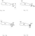
- Figure 33 shows a further design variant of a rotor blade according to the invention.
- the structure is built up by pivotable brackets 320, which can in turn be covered with a deformable film and are pivotably mounted in position points 340.
- pivotable brackets 320 By moving in the direction of the rotor blade tip (arrow), these swivel brackets can now be swiveled around the bearing points 340, for example, and thus change the rear box profile.
- Figure 30b ( Figure 30a essentially corresponds Figure 25 ) is in addition to Figure 25 an element 250 is shown on the pressure side. Since the point of application for the spring 280 is not opposite the illustration in FIG Figure 25 or 30a was changed, the elements 240 and 250 must be connected to the sheet trailing edge so that they can be pivoted about a pivot point 260. Under certain circumstances, it is advisable with this solution to form an overlap from the rotor blade box 11.0 over the element 250 along the rotor blade length.
- FIG 31b (Extension of what is in Figure 26 respectively. Figure 31a ), a pressure-side element 250 is also shown, that in the shown Case via a mechanical connection as well as the suction-side element 240 is attached to a common shaft 120.
- Figures 32a and 32b show a further development of what is already in the Figures 27a and 27b is shown. Some waves 280 are shown for corresponding elements on the pressure side.
- Figure 32a shows analog to Figure 27a a rotor blade in normal operation
- Figure 32b shows a situation in which the rear box is no longer effective due to a corresponding rotation or by moving the shafts 280.
Landscapes
- Engineering & Computer Science (AREA)
- Life Sciences & Earth Sciences (AREA)
- Sustainable Development (AREA)
- Sustainable Energy (AREA)
- Chemical & Material Sciences (AREA)
- Combustion & Propulsion (AREA)
- Mechanical Engineering (AREA)
- General Engineering & Computer Science (AREA)
- Physics & Mathematics (AREA)
- Fluid Mechanics (AREA)
- Wind Motors (AREA)
Priority Applications (1)
| Application Number | Priority Date | Filing Date | Title |
|---|---|---|---|
| EP10183781.3A EP2258943A3 (de) | 2003-04-28 | 2004-03-29 | Profil eines Rotorsblatts einer Windenergieanlage |
Applications Claiming Priority (2)
| Application Number | Priority Date | Filing Date | Title |
|---|---|---|---|
| DE10319246A DE10319246A1 (de) | 2003-04-28 | 2003-04-28 | Rotorblatt einer Windenergieanlage |
| PCT/EP2004/003294 WO2004097215A1 (de) | 2003-04-28 | 2004-03-29 | Rotorblatt einer windenergieanlage |
Related Child Applications (1)
| Application Number | Title | Priority Date | Filing Date |
|---|---|---|---|
| EP10183781.3A Division-Into EP2258943A3 (de) | 2003-04-28 | 2004-03-29 | Profil eines Rotorsblatts einer Windenergieanlage |
Publications (2)
| Publication Number | Publication Date |
|---|---|
| EP1620646A1 EP1620646A1 (de) | 2006-02-01 |
| EP1620646B1 true EP1620646B1 (de) | 2020-01-22 |
Family
ID=33393962
Family Applications (2)
| Application Number | Title | Priority Date | Filing Date |
|---|---|---|---|
| EP04723988.4A Expired - Lifetime EP1620646B1 (de) | 2003-04-28 | 2004-03-29 | Rotorblatt einer windenergieanlage |
| EP10183781.3A Withdrawn EP2258943A3 (de) | 2003-04-28 | 2004-03-29 | Profil eines Rotorsblatts einer Windenergieanlage |
Family Applications After (1)
| Application Number | Title | Priority Date | Filing Date |
|---|---|---|---|
| EP10183781.3A Withdrawn EP2258943A3 (de) | 2003-04-28 | 2004-03-29 | Profil eines Rotorsblatts einer Windenergieanlage |
Country Status (17)
Families Citing this family (73)
| Publication number | Priority date | Publication date | Assignee | Title |
|---|---|---|---|---|
| CA2488151C (en) | 2002-06-05 | 2009-04-28 | Aloys Wobben | Rotor blade for a wind power plant |
| EP2317125B1 (en) | 2005-02-22 | 2021-04-28 | Vestas Wind Systems A/S | Wind turbine and blade therefor |
| EP1845258A1 (en) | 2006-04-10 | 2007-10-17 | Siemens Aktiengesellschaft | Wind turbine rotor blade |
| DE102006017897B4 (de) * | 2006-04-13 | 2008-03-13 | Repower Systems Ag | Rotorblatt einer Windenergieanlage |
| ES2294927B1 (es) * | 2006-05-31 | 2009-02-16 | Gamesa Eolica, S.A. | Pala de aerogenerador con borde de salida divergente. |
| KR100926792B1 (ko) * | 2006-12-29 | 2009-11-13 | 한국에너지기술연구원 | 오염둔감도가 향상된 저풍속 실속제어/정속운전용풍력발전기 블레이드의 팁 에어포일 |
| US8197218B2 (en) | 2007-11-08 | 2012-06-12 | Alliance For Sustainable Energy, Llc | Quiet airfoils for small and large wind turbines |
| US20090148291A1 (en) * | 2007-12-06 | 2009-06-11 | General Electric Company | Multi-section wind turbine rotor blades and wind turbines incorporating same |
| US20090148285A1 (en) * | 2007-12-06 | 2009-06-11 | General Electric Company | Multi-section wind turbine rotor blades and wind turbines incorporating same |
| EP2078851A1 (en) | 2008-01-14 | 2009-07-15 | Lm Glasfiber A/S | Wind turbine blade and hub assembly |
| DE102008026474A1 (de) | 2008-06-03 | 2009-12-10 | Mickeler, Siegfried, Prof. Dr.-Ing. | Rotorblatt für eine Windkraftanlage sowie Windkraftanlage |
| BRPI0913564B1 (pt) * | 2008-09-19 | 2020-12-08 | Wobben Properties Gmbh | turbina eólica do tipo corredor rápido |
| WO2010043645A2 (en) * | 2008-10-14 | 2010-04-22 | Vestas Wind Systems A/S | Wind turbine blade with device for changing the aerodynamic surface or shape |
| WO2010048370A1 (en) * | 2008-10-22 | 2010-04-29 | Vec Industries, L.L.C. | Wind turbine blade and method for manufacturing thereof |
| US7837442B2 (en) * | 2008-12-03 | 2010-11-23 | General Electric Company | Root sleeve for wind turbine blade |
| US7988421B2 (en) | 2009-03-31 | 2011-08-02 | General Electric Company | Retrofit sleeve for wind turbine blade |
| DE102009002501A1 (de) | 2009-04-20 | 2010-10-28 | Wobben, Aloys | Rotorblattelement und Herstellverfahren |
| US8241000B2 (en) * | 2009-06-16 | 2012-08-14 | Heartland Energy Solutions, LLC. | Wind turbine rotor blade and airfoil section |
| US8011886B2 (en) | 2009-06-30 | 2011-09-06 | General Electric Company | Method and apparatus for increasing lift on wind turbine blade |
| US8373299B2 (en) * | 2009-12-16 | 2013-02-12 | Clear Path Energy, Llc | Axial gap rotating electrical machine |
| US9270150B2 (en) | 2009-12-16 | 2016-02-23 | Clear Path Energy, Llc | Axial gap rotating electrical machine |
| ES2513396T3 (es) * | 2010-03-18 | 2014-10-27 | Nordex Energy Gmbh | Pala de rotor de planta de energía eólica |
| EP2366892B1 (de) * | 2010-03-18 | 2014-07-30 | Nordex Energy GmbH | Windenergieanlagenrotorblatt |
| EP3199802B1 (en) * | 2010-07-16 | 2020-12-30 | LM Wind Power A/S | Wind turbine blade with narrow shoulder and relatively thick airfoil profiles |
| DE102010040596A1 (de) | 2010-09-10 | 2012-03-15 | Aloys Wobben | Abnehmbare Rotorblattspitze |
| CN102407779B (zh) * | 2010-09-21 | 2014-10-01 | 周鹏 | 动力机车发电装置 |
| JP5479300B2 (ja) * | 2010-10-22 | 2014-04-23 | 三菱重工業株式会社 | 風車翼およびこれを備えた風力発電装置ならびに風車翼の設計方法 |
| EP3179095B1 (en) * | 2010-10-22 | 2020-03-04 | Mitsubishi Heavy Industries, Ltd. | Wind turbine blade, wind power generation system including the same, and method for designing wind turbine blade |
| CN102003333B (zh) * | 2010-12-21 | 2012-01-11 | 中国科学院工程热物理研究所 | 一种具有降噪功能的风力机叶片 |
| DK2479423T3 (en) | 2011-01-24 | 2018-05-28 | Siemens Ag | Wind turbine rotor blade element |
| JP5479388B2 (ja) * | 2011-02-28 | 2014-04-23 | 三菱重工業株式会社 | 風車翼およびこれを備えた風力発電装置 |
| GB201109412D0 (en) * | 2011-06-03 | 2011-07-20 | Blade Dynamics Ltd | A wind turbine rotor |
| CN103270296B (zh) * | 2011-10-12 | 2014-05-07 | 三菱重工业株式会社 | 风车叶片及具备该风车叶片的风力发电装置以及风车叶片的设计方法 |
| DE102012209935A1 (de) * | 2011-12-08 | 2013-06-13 | Wobben Properties Gmbh | Hinterkasten, Rotorblatt mit Hinterkasten und Windenergieanlage mit solchem Rotorblatt |
| EP3722594B1 (en) | 2012-03-13 | 2023-07-05 | Wobben Properties GmbH | Wind turbine blade with flow blocking means and vortex generators |
| US11136958B2 (en) | 2012-08-06 | 2021-10-05 | Nederlandse Organisatie Voor Toegepast-Natuurwetenschappelijk Onderzoek Tno | Swallow tail airfoil |
| NL2009286C2 (en) * | 2012-08-06 | 2014-02-10 | Stichting Energie | Swallow tail airfoil. |
| EP2713044B2 (en) * | 2012-09-28 | 2022-12-07 | Siemens Gamesa Renewable Energy A/S | Wind turbine rotor blade |
| KR101331961B1 (ko) | 2012-10-23 | 2013-11-22 | 한국에너지기술연구원 | 공력제어장치 삽입이 가능한 뒷전 형상을 갖는 풍력발전기의 블레이드 에어포일 |
| ITMI20121797A1 (it) | 2012-10-23 | 2014-04-24 | Wilic Sarl | Appendice aerodinamica per una pala di un aerogeneratore e pala di aerogeneratore provvista di tale appendice aerodinamica |
| CN103133273B (zh) * | 2013-03-26 | 2015-12-02 | 国电联合动力技术有限公司 | 一种大型风机的薄翼型叶片 |
| CN103244359B (zh) * | 2013-05-30 | 2016-04-13 | 国电联合动力技术有限公司 | 一种大型风机的中等厚度翼型叶片 |
| CN103321857B (zh) * | 2013-07-08 | 2015-05-06 | 国电联合动力技术有限公司 | 一种大型风机的大厚度钝尾缘翼型叶片 |
| KR101466076B1 (ko) * | 2013-08-22 | 2014-11-28 | 삼성중공업 주식회사 | 블레이드 |
| DE102013217128A1 (de) | 2013-08-28 | 2015-03-05 | Wobben Properties Gmbh | Rotorblattelement für eine Windenergieanlage, Rotorblatt, sowie ein Herstellungsverfahren dafür und Windenergieanlage mit Rotorblatt |
| CN103711655B (zh) * | 2013-12-26 | 2016-04-06 | 中国科学院工程热物理研究所 | 一种大厚度钝尾缘风力机叶片 |
| WO2015132882A1 (ja) * | 2014-03-04 | 2015-09-11 | 中国電力株式会社 | 風力発電装置 |
| JP5886475B2 (ja) * | 2014-03-04 | 2016-03-16 | 中国電力株式会社 | 風力発電装置 |
| ITBZ20140002U1 (it) | 2014-03-13 | 2015-09-13 | Frassinelli Ernesto | Pala eolica a profilo adattivo in grado di modificare la propria struttura in base alla pressione aerodinamica che la investe, alle caratteristiche climatiche e meteorologiche del sito di installazione e, componendo con uno o piu' elementi un singolo rotore, dotare un generatore micro-eolico con asse di rotazione paralleo al flusso aerodinamico. |
| USD829172S1 (en) * | 2014-09-15 | 2018-09-25 | Raymond Cooper | Horizontal axis wind turbine with a flow-through hub, a nacelle, and a tandem blade configuration |
| USD801927S1 (en) * | 2014-09-15 | 2017-11-07 | II Raymond Cooper | Horizontal axis wind turbine with flow-through hub and nacelle and tandem blade configuration |
| US11125205B2 (en) * | 2015-09-14 | 2021-09-21 | General Electric Company | Systems and methods for joining blade components of rotor blades |
| DE102015116634A1 (de) * | 2015-10-01 | 2017-04-06 | Wobben Properties Gmbh | Windenergieanlagen-Rotorblatt und Windenergieanlage |
| DE102015220672A1 (de) | 2015-10-22 | 2017-04-27 | Wobben Properties Gmbh | Mehrschichtiges Verbundbauteil |
| DE102016213206A1 (de) | 2016-07-19 | 2018-01-25 | Wobben Properties Gmbh | Mehrschichtiges Verbundbauteil |
| EP3365166B2 (de) | 2015-10-22 | 2023-08-16 | Wobben Properties GmbH | Mehrschichtiges verbundbauteil |
| CN105626373A (zh) * | 2016-03-04 | 2016-06-01 | 云南电网有限责任公司电力科学研究院 | 一种风力机涡轮旋转叶片 |
| DE102016121554A1 (de) | 2016-11-10 | 2018-05-17 | Wobben Properties Gmbh | Mehrschichtiges Verbundbauteil |
| CN106741857A (zh) * | 2017-03-02 | 2017-05-31 | 南京那尔朴电子有限公司 | 一种可以推力调节的螺旋桨 |
| US10788016B2 (en) | 2017-05-10 | 2020-09-29 | Gerald L. Barber | Transitioning wind turbine |
| US11885297B2 (en) | 2017-05-10 | 2024-01-30 | Gerald L. Barber | Transitioning wind turbine |
| DE102017112742A1 (de) * | 2017-06-09 | 2018-12-13 | Wobben Properties Gmbh | Rotorblatt für eine Windenergieanlage und Windenergieanlage |
| DE102017124861A1 (de) | 2017-10-24 | 2019-04-25 | Wobben Properties Gmbh | Rotorblatt einer Windenergieanlage und Verfahren zu dessen Auslegung |
| US10974827B2 (en) | 2018-05-10 | 2021-04-13 | Joby Aero, Inc. | Electric tiltrotor aircraft |
| CN112219036B (zh) | 2018-06-01 | 2023-08-11 | 杰欧比飞行有限公司 | 用于飞行器噪声减轻的系统和方法 |
| WO2020009871A1 (en) | 2018-07-02 | 2020-01-09 | Joby Aero, Inc. | System and method for airspeed determination |
| WO2020061085A1 (en) | 2018-09-17 | 2020-03-26 | Joby Aero, Inc. | Aircraft control system |
| US20200331602A1 (en) * | 2018-12-07 | 2020-10-22 | Joby Aero, Inc. | Rotary airfoil and design method therefor |
| WO2020180373A2 (en) | 2018-12-07 | 2020-09-10 | Joby Aero, Inc. | Aircraft control system and method |
| EP3959770B1 (en) | 2019-04-23 | 2025-04-23 | Joby Aero, Inc. | Battery thermal management system and method |
| DE102019119027B4 (de) * | 2019-07-12 | 2022-04-28 | Wobben Properties Gmbh | Rotorblatt und Windenergieanlage |
| CN112065651B (zh) * | 2020-07-21 | 2021-12-14 | 兰州理工大学 | 一种用于风力发电机组的风轮叶片层的翼型 |
| DE102022104017A1 (de) | 2022-02-21 | 2023-08-24 | Wobben Properties Gmbh | Rotorblatt einer Windenergieanlage |
Family Cites Families (70)
| Publication number | Priority date | Publication date | Assignee | Title |
|---|---|---|---|---|
| US1403069A (en) * | 1921-08-12 | 1922-01-10 | Burne Edward Lancaster | Means for regulating the speed of wind motors |
| US2622686A (en) * | 1942-07-21 | 1952-12-23 | Chevreau Rene Louis Pier Marie | Wind motor |
| US2428936A (en) * | 1943-09-10 | 1947-10-14 | Goodrich Co B F | Aerodynamic brake |
| US2485543A (en) * | 1943-10-19 | 1949-10-25 | Andreau Jean Edouard | Power plant |
| US2465007A (en) * | 1944-01-05 | 1949-03-22 | Gen Motors Corp | Aircraft propeller |
| US2400388A (en) * | 1944-03-17 | 1946-05-14 | Goodrich Co B F | Aerodynamic brake |
| US2442783A (en) * | 1944-07-01 | 1948-06-08 | Us Sec War | Turbine rotor |
| FR908631A (fr) | 1944-08-01 | 1946-04-15 | Perfectionnements aux aéro-moteurs | |
| US2453403A (en) * | 1946-07-03 | 1948-11-09 | Charles E Bogardus | Windbreaker for parked aircraft |
| US2616509A (en) * | 1946-11-29 | 1952-11-04 | Thomas Wilfred | Pneumatic airfoil |
| US2934150A (en) * | 1955-12-21 | 1960-04-26 | United Aircraft Corp | Pressure-contoured spinner |
| US3184187A (en) * | 1963-05-10 | 1965-05-18 | Isaac Peter | Retractable airfoils and hydrofoils |
| US3463420A (en) * | 1968-02-28 | 1969-08-26 | North American Rockwell | Inflatable wing |
| US3987984A (en) * | 1973-04-09 | 1976-10-26 | Albert George Fischer | Semi-rigid aircraft wing |
| US3874816A (en) * | 1973-10-23 | 1975-04-01 | Thomas E Sweeney | Windmill blade |
| FR2290585A1 (fr) | 1974-11-07 | 1976-06-04 | Morin Bernard | Aile de rotor a profil variable, notamment pour eolienne |
| SU577300A1 (ru) | 1975-12-09 | 1977-10-25 | Свердловский Ордена Трудового Красного Знамени Горный Институт Им. В.В.Вахрушева | Лопатка турбомашины |
| DE2829716A1 (de) * | 1977-07-07 | 1979-01-25 | Univ Gakko Hojin Tokai | Windkraftmaschine mit vertikaler achse |
| JPS5928754B2 (ja) | 1979-05-18 | 1984-07-16 | 富治 高山 | 垂直軸風車の翼体 |
| US4274011A (en) * | 1980-03-14 | 1981-06-16 | Marvin Garfinkle | Wind turbine for marine propulsion |
| US4408958A (en) * | 1980-12-23 | 1983-10-11 | The Bendix Corporation | Wind turbine blade |
| DE3113079C2 (de) * | 1981-04-01 | 1985-11-21 | Messerschmitt-Bölkow-Blohm GmbH, 8000 München | Aerodynamischer Groß-Flügel und Verfahren zu dessen Herstellung |
| DE3126677A1 (de) | 1981-07-07 | 1983-01-20 | Erno-Raumfahrttechnik Gmbh, 2800 Bremen | "rotorblattausbildung fue schnellaufende rotoren" |
| US4519746A (en) * | 1981-07-24 | 1985-05-28 | United Technologies Corporation | Airfoil blade |
| US4419053A (en) * | 1981-11-20 | 1983-12-06 | Fairchild Swearingen Corporation | Propeller spinner |
| US4498017A (en) * | 1982-12-16 | 1985-02-05 | Parkins William E | Generating power from wind |
| US4692095A (en) * | 1984-04-26 | 1987-09-08 | Sir Henry Lawson-Tancred, Sons & Co. Ltd. | Wind turbine blades |
| US4699568A (en) * | 1984-06-25 | 1987-10-13 | Hartzell Propeller Inc. | Aircraft propeller with improved spinner assembly |
| US4613760A (en) * | 1984-09-12 | 1986-09-23 | The English Electric Company Limited | Power generating equipment |
| CH666728A5 (de) * | 1985-01-18 | 1988-08-15 | Escher Wyss Gmbh | Rotor einer windkraftanlage. |
| JPS61192864A (ja) * | 1985-02-20 | 1986-08-27 | Yamaha Motor Co Ltd | 風車のロ−タブレ−ド構造 |
| FR2587675A1 (fr) | 1985-09-24 | 1987-03-27 | Dumortier Paul | Ailerons a profils reversibles par autodeformation |
| FR2590229B1 (fr) * | 1985-11-19 | 1988-01-29 | Onera (Off Nat Aerospatiale) | Perfectionnements apportes aux helices aeriennes en ce qui concerne le profil de leurs pales |
| EP0283730B1 (de) | 1987-03-14 | 1992-11-04 | Mtb Manövriertechnisches Büro | Von Luft oder Wasser umströmter Strömungskörper |
| US4830574A (en) * | 1988-02-29 | 1989-05-16 | United Technologies Corporation | Airfoiled blade |
| SU1539378A1 (ru) | 1988-03-29 | 1990-01-30 | Институт Электродинамики Ан Усср | Лопасть ветроколеса |
| US4976587A (en) * | 1988-07-20 | 1990-12-11 | Dwr Wind Technologies Inc. | Composite wind turbine rotor blade and method for making same |
| GB8829836D0 (en) | 1988-12-21 | 1989-02-15 | British Aerospace | Wing flap hoot suppression |
| GB2227286A (en) * | 1989-01-17 | 1990-07-25 | Howden Wind Turbines Limited | Control of a wind turbine and adjustable blade therefor |
| DE3913505A1 (de) * | 1989-04-25 | 1989-11-16 | Astrid Holzem | Fluegel mit aerodynamischer bremse fuer windkraftmaschinen |
| DE4002972C2 (de) | 1990-02-01 | 1994-06-16 | Guenter Waldherr | Tragflügel mit veränderbarem Profil, insbesondere zur Verwendung als Segel |
| JPH05189146A (ja) | 1992-01-16 | 1993-07-30 | Hiroo Yasui | トラックボール・マウス |
| US5527151A (en) * | 1992-03-04 | 1996-06-18 | Northern Power Systems, Inc. | Advanced wind turbine with lift-destroying aileron for shutdown |
| IL105107A (en) * | 1992-03-18 | 1996-06-18 | Advanced Wind Turbines Inc | Wind turbines |
| US5320491A (en) * | 1992-07-09 | 1994-06-14 | Northern Power Systems, Inc. | Wind turbine rotor aileron |
| US5417548A (en) * | 1994-01-14 | 1995-05-23 | Midwest Research Institute | Root region airfoil for wind turbine |
| US5562420A (en) * | 1994-03-14 | 1996-10-08 | Midwest Research Institute | Airfoils for wind turbine |
| DE4428731A1 (de) | 1994-08-15 | 1996-02-22 | Infan Gmbh Ingenieurgesellscha | Längenvariables Rotorblatt für Windkraftanlagen, insbesondere für Windkraftanlagen an Binnenlandstandorten |
| DE4435606A1 (de) | 1994-10-06 | 1996-04-11 | Manfred Dipl Ing Maibom | Flügel mit veränderbarer Form bezüglich der Wechselwirkung mit dem strömenden Medium |
| US5570859A (en) * | 1995-01-09 | 1996-11-05 | Quandt; Gene A. | Aerodynamic braking device |
| US5570997A (en) * | 1995-07-17 | 1996-11-05 | Pratt; Charles W. | Horizontal windmill with folding blades |
| GB2311978A (en) | 1996-04-10 | 1997-10-15 | Robert Pyatt | Adjustable wing |
| DE19719221C1 (de) | 1997-05-07 | 1998-10-29 | Roland Stelzer | Rotorblatt, insbesondere für Windkraftanlagen |
| US6420795B1 (en) * | 1998-08-08 | 2002-07-16 | Zond Energy Systems, Inc. | Variable speed wind turbine generator |
| US6068446A (en) * | 1997-11-20 | 2000-05-30 | Midwest Research Institute | Airfoils for wind turbine |
| US6015115A (en) * | 1998-03-25 | 2000-01-18 | Lockheed Martin Corporation | Inflatable structures to control aircraft |
| US6133716A (en) * | 1998-10-23 | 2000-10-17 | Statordyne, Inc. | High-efficiency high-power uninterrupted power system |
| ES2178903B1 (es) * | 1999-05-31 | 2004-03-16 | Torres Martinez M | Pala para aerogenerador. |
| DE19962989B4 (de) * | 1999-12-24 | 2006-04-13 | Wobben, Aloys, Dipl.-Ing. | Rotorblatt für Windenergieanlagen |
| DE10003385A1 (de) * | 2000-01-26 | 2001-08-02 | Aloys Wobben | Windenergieanlage |
| US6503058B1 (en) * | 2000-05-01 | 2003-01-07 | Zond Energy Systems, Inc. | Air foil configuration for wind turbine |
| US6523781B2 (en) * | 2000-08-30 | 2003-02-25 | Gary Dean Ragner | Axial-mode linear wind-turbine |
| US6951443B1 (en) * | 2000-09-08 | 2005-10-04 | General Electric Company | Wind turbine ring/shroud drive system |
| BR0116502B1 (pt) * | 2000-12-23 | 2009-12-01 | lámina de rotor para uma instalação de energia eólica, e, instalação de energia eólica. | |
| US6682302B2 (en) * | 2001-03-20 | 2004-01-27 | James D. Noble | Turbine apparatus and method |
| US6465902B1 (en) * | 2001-04-18 | 2002-10-15 | The United States Of America As Represented By The Secretary Of The Navy | Controllable camber windmill blades |
| US7059833B2 (en) * | 2001-11-26 | 2006-06-13 | Bonus Energy A/S | Method for improvement of the efficiency of a wind turbine rotor |
| CA2488151C (en) * | 2002-06-05 | 2009-04-28 | Aloys Wobben | Rotor blade for a wind power plant |
| DE10307682A1 (de) * | 2002-06-05 | 2004-01-08 | Aloys Wobben | Rotorblatt einer Windenergieanlage |
| USD584686S1 (en) * | 2007-07-23 | 2009-01-13 | Aloys Wobben | Nacelle of a wind turbine |
-
2003
- 2003-04-28 DE DE10319246A patent/DE10319246A1/de not_active Withdrawn
-
2004
- 2004-03-29 PT PT47239884T patent/PT1620646T/pt unknown
- 2004-03-29 ES ES04723988T patent/ES2778830T3/es not_active Expired - Lifetime
- 2004-03-29 EP EP04723988.4A patent/EP1620646B1/de not_active Expired - Lifetime
- 2004-03-29 WO PCT/EP2004/003294 patent/WO2004097215A1/de active Application Filing
- 2004-03-29 EP EP10183781.3A patent/EP2258943A3/de not_active Withdrawn
- 2004-03-29 CA CA2524208A patent/CA2524208C/en not_active Expired - Fee Related
- 2004-03-29 US US10/554,628 patent/US7946803B2/en active Active
- 2004-03-29 CA CA2683764A patent/CA2683764C/en not_active Expired - Fee Related
- 2004-03-29 BR BRPI0409782-3A patent/BRPI0409782B1/pt not_active IP Right Cessation
- 2004-03-29 KR KR1020057020515A patent/KR100812796B1/ko not_active Expired - Fee Related
- 2004-03-29 DK DK04723988.4T patent/DK1620646T3/da active
- 2004-03-29 JP JP2006504897A patent/JP4504971B2/ja not_active Expired - Fee Related
- 2004-03-29 NZ NZ543574A patent/NZ543574A/en not_active IP Right Cessation
- 2004-03-29 CN CNB2004800114863A patent/CN100366893C/zh not_active Expired - Fee Related
- 2004-03-29 AU AU2004234487A patent/AU2004234487B2/en not_active Ceased
- 2004-04-28 AR ARP040101437A patent/AR046912A1/es not_active Application Discontinuation
-
2005
- 2005-10-14 ZA ZA200508323A patent/ZA200508323B/en unknown
- 2005-11-25 NO NO20055599A patent/NO20055599L/no not_active Application Discontinuation
-
2009
- 2009-10-23 JP JP2009244773A patent/JP5334796B2/ja not_active Expired - Fee Related
Non-Patent Citations (1)
| Title |
|---|
| "Niedrig-geschwindigkeits-profile", 1 January 1996, VIEWEG&SOHN VERLAGSGESELLSCCHAFT MBH, LENGERICH, DEUTSCHLAND, ISBN: 978-3-52-803820-5, article DIETER ALTHAUS: "Cambered Airfoils without Flaps for use in Wind Turbines", pages: 157 - 159, XP055079965 * |
Also Published As
| Publication number | Publication date |
|---|---|
| KR100812796B1 (ko) | 2008-03-12 |
| KR20060017761A (ko) | 2006-02-27 |
| CA2524208A1 (en) | 2004-11-11 |
| NZ543574A (en) | 2009-02-28 |
| EP1620646A1 (de) | 2006-02-01 |
| CN100366893C (zh) | 2008-02-06 |
| CA2683764A1 (en) | 2004-11-11 |
| JP2010043650A (ja) | 2010-02-25 |
| BRPI0409782B1 (pt) | 2014-05-20 |
| EP2258943A2 (de) | 2010-12-08 |
| EP2258943A3 (de) | 2013-10-02 |
| DE10319246A1 (de) | 2004-12-16 |
| ZA200508323B (en) | 2006-06-28 |
| ES2778830T3 (es) | 2020-08-12 |
| AU2004234487A1 (en) | 2004-11-11 |
| PT1620646T (pt) | 2020-04-23 |
| AR046912A1 (es) | 2006-01-04 |
| US7946803B2 (en) | 2011-05-24 |
| DK1620646T3 (da) | 2020-04-14 |
| JP4504971B2 (ja) | 2010-07-14 |
| JP5334796B2 (ja) | 2013-11-06 |
| JP2006524772A (ja) | 2006-11-02 |
| US20070036657A1 (en) | 2007-02-15 |
| CN1780982A (zh) | 2006-05-31 |
| CA2524208C (en) | 2012-02-28 |
| WO2004097215A1 (de) | 2004-11-11 |
| BRPI0409782A (pt) | 2006-05-30 |
| AU2004234487B2 (en) | 2009-02-19 |
| CA2683764C (en) | 2013-04-30 |
| NO20055599L (no) | 2005-11-25 |
Similar Documents
| Publication | Publication Date | Title |
|---|---|---|
| EP1620646B1 (de) | Rotorblatt einer windenergieanlage | |
| EP1350027B1 (de) | Rotorblatt für eine windenergieanlage | |
| EP1514023B1 (de) | Windenergieanlage | |
| DE102005034078B4 (de) | Windkraftanlagen-Rotorblatt mit in der Ebene liegender Pfeilung und Vorrichtungen welche dasselbe verwenden, und Verfahren für dessen Herstellung | |
| EP2280163B1 (de) | Windenergieanlage sowie Rotorblatt für eine Windenergieanlage | |
| EP2339171B1 (de) | Rotorblatt für eine Windkraftanlage | |
| EP3008331B1 (de) | Rotorblatt einer windenergieanlage und windenergieanlage | |
| EP3755899B1 (de) | Rotorblatt einer windenergieanlage mit einer splitterplatte | |
| DE2632697A1 (de) | Windkraftmaschine | |
| EP3377759B1 (de) | Steuerung einer windenergieanlage mit verstellbaren rotorblättern | |
| WO2009146810A2 (de) | Rotorblatt für eine windkraftanlage sowie windkraftanlage | |
| DE102011051831A1 (de) | Rotorblatt für eine Windkraftanlage mit einem Saugseitenwinglet | |
| EP3330530A1 (de) | Rotorblatt einer windenergieanlage | |
| EP1244872A1 (de) | Rotorblatt für eine windenergieanlage | |
| EP3981981B1 (de) | Rotorblatt für eine windenergieanlage, windenergieanlage und verfahren zur auslegung eines rotorblatts | |
| EP3399183B1 (de) | Rotorblatt einer windenergieanlage | |
| EP2976524B1 (de) | Rotorblatt einer windenergieanlage, windenergieanlage und verfahren zum betreiben einer windenergieanlage | |
| DE10152449A1 (de) | Rotorblatt für eine Windenergieanlage | |
| AT408022B (de) | Windturbine mit vertikaler oder geneigter achse und auftriebsausnutzung | |
| DE10064912B4 (de) | Rotorblatt für eine Windenergieanlage | |
| DE102010041520B4 (de) | Rotorblatt und Verfahren zum Betrieb einer Windenergieanlage | |
| EP3280910A1 (de) | Windenergieanlagen-rotorblatt |
Legal Events
| Date | Code | Title | Description |
|---|---|---|---|
| PUAI | Public reference made under article 153(3) epc to a published international application that has entered the european phase |
Free format text: ORIGINAL CODE: 0009012 |
|
| 17P | Request for examination filed |
Effective date: 20051128 |
|
| AK | Designated contracting states |
Kind code of ref document: A1 Designated state(s): AT BE BG CH CY CZ DE DK EE ES FI FR GB GR HU IE IT LI LU MC NL PL PT RO SE SI SK TR |
|
| AX | Request for extension of the european patent |
Extension state: LV |
|
| RAX | Requested extension states of the european patent have changed |
Extension state: LV Payment date: 20051128 |
|
| 17Q | First examination report despatched |
Effective date: 20080131 |
|
| RAX | Requested extension states of the european patent have changed |
Extension state: LV Payment date: 20051128 Extension state: LT Payment date: 20051128 |
|
| RAP1 | Party data changed (applicant data changed or rights of an application transferred) |
Owner name: WOBBEN PROPERTIES GMBH |
|
| RIN1 | Information on inventor provided before grant (corrected) |
Inventor name: WOBBEN PROPERTIES GMBH |
|
| RAP1 | Party data changed (applicant data changed or rights of an application transferred) |
Owner name: WOBBEN PROPERTIES GMBH |
|
| RIN1 | Information on inventor provided before grant (corrected) |
Inventor name: WOBBEN PROPERTIES GMBH |
|
| RIN1 | Information on inventor provided before grant (corrected) |
Inventor name: DER ERFINDER HAT AUF SEINE NENNUNG VERZICHTET. |
|
| RIN1 | Information on inventor provided before grant (corrected) |
Inventor name: WOBBEN, ALOYS |
|
| STAA | Information on the status of an ep patent application or granted ep patent |
Free format text: STATUS: EXAMINATION IS IN PROGRESS |
|
| GRAP | Despatch of communication of intention to grant a patent |
Free format text: ORIGINAL CODE: EPIDOSNIGR1 |
|
| STAA | Information on the status of an ep patent application or granted ep patent |
Free format text: STATUS: GRANT OF PATENT IS INTENDED |
|
| INTG | Intention to grant announced |
Effective date: 20190918 |
|
| GRAS | Grant fee paid |
Free format text: ORIGINAL CODE: EPIDOSNIGR3 |
|
| GRAA | (expected) grant |
Free format text: ORIGINAL CODE: 0009210 |
|
| STAA | Information on the status of an ep patent application or granted ep patent |
Free format text: STATUS: THE PATENT HAS BEEN GRANTED |
|
| REG | Reference to a national code |
Ref country code: DE Ref legal event code: R081 Ref document number: 502004015846 Country of ref document: DE Owner name: WOBBEN PROPERTIES GMBH, DE Free format text: FORMER OWNER: WOBBEN, ALOYS, 26607 AURICH, DE |
|
| AK | Designated contracting states |
Kind code of ref document: B1 Designated state(s): AT BE BG CH CY CZ DE DK EE ES FI FR GB GR HU IE IT LI LU MC NL PL PT RO SE SI SK TR |
|
| AX | Request for extension of the european patent |
Extension state: LT LV |
|
| REG | Reference to a national code |
Ref country code: GB Ref legal event code: FG4D Free format text: NOT ENGLISH |
|
| REG | Reference to a national code |
Ref country code: CH Ref legal event code: EP |
|
| REG | Reference to a national code |
Ref country code: AT Ref legal event code: REF Ref document number: 1227063 Country of ref document: AT Kind code of ref document: T Effective date: 20200215 |
|
| REG | Reference to a national code |
Ref country code: IE Ref legal event code: FG4D Free format text: LANGUAGE OF EP DOCUMENT: GERMAN |
|
| REG | Reference to a national code |
Ref country code: DE Ref legal event code: R096 Ref document number: 502004015846 Country of ref document: DE |
|
| REG | Reference to a national code |
Ref country code: DK Ref legal event code: T3 Effective date: 20200407 |
|
| REG | Reference to a national code |
Ref country code: PT Ref legal event code: SC4A Ref document number: 1620646 Country of ref document: PT Date of ref document: 20200423 Kind code of ref document: T Free format text: AVAILABILITY OF NATIONAL TRANSLATION Effective date: 20200415 |
|
| REG | Reference to a national code |
Ref country code: NL Ref legal event code: FP |
|
| PGFP | Annual fee paid to national office [announced via postgrant information from national office to epo] |
Ref country code: AT Payment date: 20200319 Year of fee payment: 17 |
|
| REG | Reference to a national code |
Ref country code: SE Ref legal event code: TRGR |
|
| REG | Reference to a national code |
Ref country code: LT Ref legal event code: MG9D |
|
| PG25 | Lapsed in a contracting state [announced via postgrant information from national office to epo] |
Ref country code: FI Free format text: LAPSE BECAUSE OF FAILURE TO SUBMIT A TRANSLATION OF THE DESCRIPTION OR TO PAY THE FEE WITHIN THE PRESCRIBED TIME-LIMIT Effective date: 20200122 |
|
| PGFP | Annual fee paid to national office [announced via postgrant information from national office to epo] |
Ref country code: ES Payment date: 20200421 Year of fee payment: 17 Ref country code: PT Payment date: 20200526 Year of fee payment: 17 |
|
| REG | Reference to a national code |
Ref country code: ES Ref legal event code: FG2A Ref document number: 2778830 Country of ref document: ES Kind code of ref document: T3 Effective date: 20200812 |
|
| PG25 | Lapsed in a contracting state [announced via postgrant information from national office to epo] |
Ref country code: GR Free format text: LAPSE BECAUSE OF FAILURE TO SUBMIT A TRANSLATION OF THE DESCRIPTION OR TO PAY THE FEE WITHIN THE PRESCRIBED TIME-LIMIT Effective date: 20200423 Ref country code: BG Free format text: LAPSE BECAUSE OF FAILURE TO SUBMIT A TRANSLATION OF THE DESCRIPTION OR TO PAY THE FEE WITHIN THE PRESCRIBED TIME-LIMIT Effective date: 20200422 |
|
| PGFP | Annual fee paid to national office [announced via postgrant information from national office to epo] |
Ref country code: SE Payment date: 20200325 Year of fee payment: 17 |
|
| REG | Reference to a national code |
Ref country code: DE Ref legal event code: R097 Ref document number: 502004015846 Country of ref document: DE |
|
| PG25 | Lapsed in a contracting state [announced via postgrant information from national office to epo] |
Ref country code: EE Free format text: LAPSE BECAUSE OF FAILURE TO SUBMIT A TRANSLATION OF THE DESCRIPTION OR TO PAY THE FEE WITHIN THE PRESCRIBED TIME-LIMIT Effective date: 20200122 Ref country code: RO Free format text: LAPSE BECAUSE OF FAILURE TO SUBMIT A TRANSLATION OF THE DESCRIPTION OR TO PAY THE FEE WITHIN THE PRESCRIBED TIME-LIMIT Effective date: 20200122 Ref country code: SK Free format text: LAPSE BECAUSE OF FAILURE TO SUBMIT A TRANSLATION OF THE DESCRIPTION OR TO PAY THE FEE WITHIN THE PRESCRIBED TIME-LIMIT Effective date: 20200122 Ref country code: CZ Free format text: LAPSE BECAUSE OF FAILURE TO SUBMIT A TRANSLATION OF THE DESCRIPTION OR TO PAY THE FEE WITHIN THE PRESCRIBED TIME-LIMIT Effective date: 20200122 Ref country code: MC Free format text: LAPSE BECAUSE OF FAILURE TO SUBMIT A TRANSLATION OF THE DESCRIPTION OR TO PAY THE FEE WITHIN THE PRESCRIBED TIME-LIMIT Effective date: 20200122 |
|
| REG | Reference to a national code |
Ref country code: CH Ref legal event code: PL |
|
| PLBE | No opposition filed within time limit |
Free format text: ORIGINAL CODE: 0009261 |
|
| STAA | Information on the status of an ep patent application or granted ep patent |
Free format text: STATUS: NO OPPOSITION FILED WITHIN TIME LIMIT |
|
| REG | Reference to a national code |
Ref country code: BE Ref legal event code: MM Effective date: 20200331 |
|
| 26N | No opposition filed |
Effective date: 20201023 |
|
| PG25 | Lapsed in a contracting state [announced via postgrant information from national office to epo] |
Ref country code: LU Free format text: LAPSE BECAUSE OF NON-PAYMENT OF DUE FEES Effective date: 20200329 |
|
| PG25 | Lapsed in a contracting state [announced via postgrant information from national office to epo] |
Ref country code: IT Free format text: LAPSE BECAUSE OF FAILURE TO SUBMIT A TRANSLATION OF THE DESCRIPTION OR TO PAY THE FEE WITHIN THE PRESCRIBED TIME-LIMIT Effective date: 20200122 Ref country code: LI Free format text: LAPSE BECAUSE OF NON-PAYMENT OF DUE FEES Effective date: 20200331 Ref country code: CH Free format text: LAPSE BECAUSE OF NON-PAYMENT OF DUE FEES Effective date: 20200331 Ref country code: IE Free format text: LAPSE BECAUSE OF NON-PAYMENT OF DUE FEES Effective date: 20200329 |
|
| PG25 | Lapsed in a contracting state [announced via postgrant information from national office to epo] |
Ref country code: BE Free format text: LAPSE BECAUSE OF NON-PAYMENT OF DUE FEES Effective date: 20200331 Ref country code: SI Free format text: LAPSE BECAUSE OF FAILURE TO SUBMIT A TRANSLATION OF THE DESCRIPTION OR TO PAY THE FEE WITHIN THE PRESCRIBED TIME-LIMIT Effective date: 20200122 Ref country code: PL Free format text: LAPSE BECAUSE OF FAILURE TO SUBMIT A TRANSLATION OF THE DESCRIPTION OR TO PAY THE FEE WITHIN THE PRESCRIBED TIME-LIMIT Effective date: 20200122 |
|
| REG | Reference to a national code |
Ref country code: AT Ref legal event code: MM01 Ref document number: 1227063 Country of ref document: AT Kind code of ref document: T Effective date: 20210329 |
|
| PG25 | Lapsed in a contracting state [announced via postgrant information from national office to epo] |
Ref country code: PT Free format text: LAPSE BECAUSE OF NON-PAYMENT OF DUE FEES Effective date: 20211229 Ref country code: AT Free format text: LAPSE BECAUSE OF NON-PAYMENT OF DUE FEES Effective date: 20210329 Ref country code: SE Free format text: LAPSE BECAUSE OF NON-PAYMENT OF DUE FEES Effective date: 20210330 |
|
| REG | Reference to a national code |
Ref country code: ES Ref legal event code: FD2A Effective date: 20220523 |
|
| PG25 | Lapsed in a contracting state [announced via postgrant information from national office to epo] |
Ref country code: TR Free format text: LAPSE BECAUSE OF FAILURE TO SUBMIT A TRANSLATION OF THE DESCRIPTION OR TO PAY THE FEE WITHIN THE PRESCRIBED TIME-LIMIT Effective date: 20200122 Ref country code: CY Free format text: LAPSE BECAUSE OF FAILURE TO SUBMIT A TRANSLATION OF THE DESCRIPTION OR TO PAY THE FEE WITHIN THE PRESCRIBED TIME-LIMIT Effective date: 20200122 |
|
| PG25 | Lapsed in a contracting state [announced via postgrant information from national office to epo] |
Ref country code: ES Free format text: LAPSE BECAUSE OF NON-PAYMENT OF DUE FEES Effective date: 20210330 |
|
| PGFP | Annual fee paid to national office [announced via postgrant information from national office to epo] |
Ref country code: FR Payment date: 20230320 Year of fee payment: 20 Ref country code: DK Payment date: 20230323 Year of fee payment: 20 |
|
| PGFP | Annual fee paid to national office [announced via postgrant information from national office to epo] |
Ref country code: GB Payment date: 20230323 Year of fee payment: 20 Ref country code: DE Payment date: 20220629 Year of fee payment: 20 |
|
| PGFP | Annual fee paid to national office [announced via postgrant information from national office to epo] |
Ref country code: NL Payment date: 20230322 Year of fee payment: 20 |
|
| REG | Reference to a national code |
Ref country code: DE Ref legal event code: R071 Ref document number: 502004015846 Country of ref document: DE |
|
| REG | Reference to a national code |
Ref country code: DK Ref legal event code: EUP Expiry date: 20240329 |
|
| REG | Reference to a national code |
Ref country code: NL Ref legal event code: MK Effective date: 20240328 |
|
| REG | Reference to a national code |
Ref country code: GB Ref legal event code: PE20 Expiry date: 20240328 |
|
| PG25 | Lapsed in a contracting state [announced via postgrant information from national office to epo] |
Ref country code: GB Free format text: LAPSE BECAUSE OF EXPIRATION OF PROTECTION Effective date: 20240328 |