EP1620646B1 - Rotor blade of a wind energy facility - Google Patents
Rotor blade of a wind energy facility Download PDFInfo
- Publication number
- EP1620646B1 EP1620646B1 EP04723988.4A EP04723988A EP1620646B1 EP 1620646 B1 EP1620646 B1 EP 1620646B1 EP 04723988 A EP04723988 A EP 04723988A EP 1620646 B1 EP1620646 B1 EP 1620646B1
- Authority
- EP
- European Patent Office
- Prior art keywords
- rotor blade
- power system
- wind power
- rotor
- wind
- Prior art date
- Legal status (The legal status is an assumption and is not a legal conclusion. Google has not performed a legal analysis and makes no representation as to the accuracy of the status listed.)
- Expired - Lifetime
Links
- 238000009434 installation Methods 0.000 claims description 12
- 238000005192 partition Methods 0.000 claims 2
- 230000002829 reductive effect Effects 0.000 description 14
- 238000013461 design Methods 0.000 description 10
- 238000004804 winding Methods 0.000 description 10
- 230000007423 decrease Effects 0.000 description 6
- 230000000694 effects Effects 0.000 description 5
- 210000002435 tendon Anatomy 0.000 description 5
- 238000010276 construction Methods 0.000 description 3
- 238000011161 development Methods 0.000 description 3
- 230000018109 developmental process Effects 0.000 description 3
- 238000000926 separation method Methods 0.000 description 3
- 238000004026 adhesive bonding Methods 0.000 description 2
- 238000005253 cladding Methods 0.000 description 2
- 230000006835 compression Effects 0.000 description 2
- 238000007906 compression Methods 0.000 description 2
- 230000000717 retained effect Effects 0.000 description 2
- UJCHIZDEQZMODR-BYPYZUCNSA-N (2r)-2-acetamido-3-sulfanylpropanamide Chemical compound CC(=O)N[C@@H](CS)C(N)=O UJCHIZDEQZMODR-BYPYZUCNSA-N 0.000 description 1
- 241001669680 Dormitator maculatus Species 0.000 description 1
- 230000015572 biosynthetic process Effects 0.000 description 1
- 230000000295 complement effect Effects 0.000 description 1
- 230000003247 decreasing effect Effects 0.000 description 1
- 230000001419 dependent effect Effects 0.000 description 1
- 238000006073 displacement reaction Methods 0.000 description 1
- 238000009826 distribution Methods 0.000 description 1
- 238000011156 evaluation Methods 0.000 description 1
- 230000002349 favourable effect Effects 0.000 description 1
- 238000003306 harvesting Methods 0.000 description 1
- 238000005259 measurement Methods 0.000 description 1
- 230000002093 peripheral effect Effects 0.000 description 1
- 230000001105 regulatory effect Effects 0.000 description 1
- 230000002441 reversible effect Effects 0.000 description 1
- 230000003068 static effect Effects 0.000 description 1
- 238000012546 transfer Methods 0.000 description 1
- 238000009827 uniform distribution Methods 0.000 description 1
Images


Classifications
-
- F—MECHANICAL ENGINEERING; LIGHTING; HEATING; WEAPONS; BLASTING
- F03—MACHINES OR ENGINES FOR LIQUIDS; WIND, SPRING, OR WEIGHT MOTORS; PRODUCING MECHANICAL POWER OR A REACTIVE PROPULSIVE THRUST, NOT OTHERWISE PROVIDED FOR
- F03D—WIND MOTORS
- F03D1/00—Wind motors with rotation axis substantially parallel to the air flow entering the rotor
- F03D1/06—Rotors
- F03D1/0608—Rotors characterised by their aerodynamic shape
- F03D1/0633—Rotors characterised by their aerodynamic shape of the blades
- F03D1/0641—Rotors characterised by their aerodynamic shape of the blades of the section profile of the blades, i.e. aerofoil profile
-
- F—MECHANICAL ENGINEERING; LIGHTING; HEATING; WEAPONS; BLASTING
- F03—MACHINES OR ENGINES FOR LIQUIDS; WIND, SPRING, OR WEIGHT MOTORS; PRODUCING MECHANICAL POWER OR A REACTIVE PROPULSIVE THRUST, NOT OTHERWISE PROVIDED FOR
- F03D—WIND MOTORS
- F03D1/00—Wind motors with rotation axis substantially parallel to the air flow entering the rotor
- F03D1/06—Rotors
- F03D1/065—Rotors characterised by their construction elements
- F03D1/0675—Rotors characterised by their construction elements of the blades
-
- F—MECHANICAL ENGINEERING; LIGHTING; HEATING; WEAPONS; BLASTING
- F05—INDEXING SCHEMES RELATING TO ENGINES OR PUMPS IN VARIOUS SUBCLASSES OF CLASSES F01-F04
- F05B—INDEXING SCHEME RELATING TO WIND, SPRING, WEIGHT, INERTIA OR LIKE MOTORS, TO MACHINES OR ENGINES FOR LIQUIDS COVERED BY SUBCLASSES F03B, F03D AND F03G
- F05B2240/00—Components
- F05B2240/20—Rotors
- F05B2240/30—Characteristics of rotor blades, i.e. of any element transforming dynamic fluid energy to or from rotational energy and being attached to a rotor
- F05B2240/31—Characteristics of rotor blades, i.e. of any element transforming dynamic fluid energy to or from rotational energy and being attached to a rotor of changeable form or shape
- F05B2240/311—Characteristics of rotor blades, i.e. of any element transforming dynamic fluid energy to or from rotational energy and being attached to a rotor of changeable form or shape flexible or elastic
-
- Y—GENERAL TAGGING OF NEW TECHNOLOGICAL DEVELOPMENTS; GENERAL TAGGING OF CROSS-SECTIONAL TECHNOLOGIES SPANNING OVER SEVERAL SECTIONS OF THE IPC; TECHNICAL SUBJECTS COVERED BY FORMER USPC CROSS-REFERENCE ART COLLECTIONS [XRACs] AND DIGESTS
- Y02—TECHNOLOGIES OR APPLICATIONS FOR MITIGATION OR ADAPTATION AGAINST CLIMATE CHANGE
- Y02E—REDUCTION OF GREENHOUSE GAS [GHG] EMISSIONS, RELATED TO ENERGY GENERATION, TRANSMISSION OR DISTRIBUTION
- Y02E10/00—Energy generation through renewable energy sources
- Y02E10/70—Wind energy
- Y02E10/72—Wind turbines with rotation axis in wind direction
Landscapes
- Engineering & Computer Science (AREA)
- Life Sciences & Earth Sciences (AREA)
- Sustainable Development (AREA)
- Sustainable Energy (AREA)
- Chemical & Material Sciences (AREA)
- Combustion & Propulsion (AREA)
- Mechanical Engineering (AREA)
- General Engineering & Computer Science (AREA)
- Physics & Mathematics (AREA)
- Fluid Mechanics (AREA)
- Wind Motors (AREA)
Description
Die Erfindung betrifft ein Rotorblatt einer Windenergieanlage sowie eine Windenergieanlage.The invention relates to a rotor blade of a wind energy installation and a wind energy installation.
Als Stand der Technik hierzu sei allgemein auf das Buch "
Als allgemeiner weiterer Stand der Technik sei auf die Dokumente
Rotorblätter sind anhand einer Vielzahl von Aspekten zu optimieren. Einerseits sollen sie leise sein, andererseits sollen sie auch eine maximale dynamische Leistung bereitstellen, damit bei schon recht geringem Wind die Windenergieanlage zu laufen beginnt und bei möglichst geringen Windstärken bereits die Nennwindgeschwindigkeit erreicht wird, also die Geschwindigkeit, bei welcher auch erstmals die Nennleistung der Windenergieanlage erreicht wird. Steigt dann die Windgeschwindigkeit weiter an, so wird heutzutage bei pitchregulierten Windenergieanlagen das Rotorblatt immer mehr in den Wind gestellt, so dass die Nennleistung weiter erhalten bleibt, die Angriffsfläche des Rotorblatts zum Wind jedoch abnimmt, um somit die gesamte Windenergieanlage bzw. ihre Teile vor mechanischen Schäden zu schützen. Entscheidend ist aber, dass den aerodynamischen Eigenschaften der Rotorblattprofile des Rotorblatts einer Windenergieanlage eine große Bedeutung zukommt.Rotor blades can be optimized based on a variety of aspects. On the one hand, they should be quiet, on the other hand, they should also provide maximum dynamic performance, so that the wind turbine can be used when the wind is quite light starts to run and the nominal wind speed is already reached with the lowest possible wind strengths, i.e. the speed at which the nominal power of the wind turbine is also achieved for the first time. If the wind speed then continues to increase, nowadays in pitch-regulated wind turbines the rotor blade is placed more and more in the wind, so that the nominal power is retained, but the surface area of the rotor blade exposed to the wind decreases, in order to prevent the entire wind turbine or its parts from becoming mechanical Protect damage. It is crucial, however, that the aerodynamic properties of the rotor blade profiles of the rotor blade of a wind turbine are of great importance.
Aufgabe der vorliegenden Erfindung ist es, ein Rotorblatt mit einem Rotorblattprofil bzw. eine Windenergieanlage anzugeben, welches bzw. welche eine bessere Leistungsfähigkeit als bisher aufweist.The object of the present invention is to provide a rotor blade with a rotor blade profile or a wind power plant which has a better performance than before.
Die Aufgabe wird erfindungsgemäß mit einem Rotorblatt mit einem Rotorblattprofil mit den Merkmalen nach dem unabhängigen Anspruch gelöst.The object is achieved with a rotor blade with a rotor blade profile with the features according to the independent claim.
Vorteilhafte Weiterbildungen sind in den abhängigen Ansprüchen beschrieben.Advantageous further developments are described in the dependent claims.
Die konkreten Koordinaten eines erfindungsgemäßen Rotorblattprofils nach der Erfindung sind in einer Tabelle 1 angegeben.The specific coordinates of a rotor blade profile according to the invention are given in Table 1.
Die Erfindung ist nachfolgend von mehreren Zeichnungen dargestellt. Hierin zeigen:
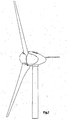
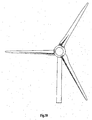
- Fig. 1
- eine Ansicht einer erfindungsgemäßen Windenergieanlage aus einer Perspektive von vorne,
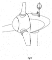
- Fig. 2
- eine Ansicht einer erfindungsgemäßen Windenergieanlage aus einer Perspektive von seitlich hinten,
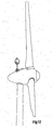
- Fig. 3
- die Ansicht einer erfindungsgemäßen Windenergieanlage von der Seite,
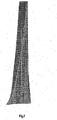
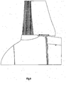
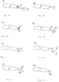
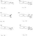
- Fig. 4-8
- Ansichten eines erfindungsgemäßen Rotorblatts aus verschiedenen Richtungen
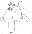
- Fig. 9
- eine vergrößerte Ansicht einer erfindungsgemäßen Windenergieanlage
- Fig. 10
- eine Ansicht eines erfindungsgemäßen Rotorblatts
- Fig. 11-17,19
- verschiedene Ansichten einer erfindungsgemäßen Windenergieanlage
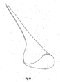
- Fig. 18
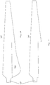
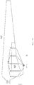
- einen Querschnitt eines erfindungsgemäßen Rotorblatts (im nabennahen Bereich)
- Fig. 1
- a view of a wind turbine according to the invention from a perspective from the front,
- Fig. 2
- 2 shows a view of a wind power installation according to the invention from a perspective from the side,
- Fig. 3
- the view of a wind turbine according to the invention from the side,
- Fig. 4-8
- Views of a rotor blade according to the invention from different directions
- Fig. 9
- an enlarged view of a wind turbine according to the invention
- Fig. 10
- a view of a rotor blade according to the invention
- Figures 11-17, 19
- different views of a wind turbine according to the invention
- Fig. 18
- a cross section of a rotor blade according to the invention (in the area near the hub)
Das gemäß der vorliegenden Anmeldung beschriebene Rotorblattprofil ist im Besonderen in dem Bereich des Rotorblatts ausgebildet, der dem Rotorblattanschluss (zum Anschluss an die Nabe) anschließt. Bevorzugt ist das in der vorliegenden Anmeldung beschriebene Profil im ersten Drittel des Rotorblatts, - bezogen auf die Gesamtlänge des Rotorblatts, ausgebildet. Die Gesamtlänge eines Rotorblatts kann hierbei durchaus im Bereich von 10 m bis 70 m liegen, je nachdem, welche Nennleistung eine Windenergieanlage haben soll. So beträgt beispielsweise die Nennleistung einer Windenergieanlage der Firma Enercon vom Typ E-112 (Durchmesser ca. 112 m) 4,5 MW, die Nenn-Leistung einer Windenergieanlage der Firma Enercon vom Typ E-30 beträgt hingegen 300 KW.The rotor blade profile described according to the present application is in particular formed in the area of the rotor blade that connects to the rotor blade connection (for connection to the hub). The profile described in the present application is preferably formed in the first third of the rotor blade, based on the total length of the rotor blade. The total length of a rotor blade can be in the range of 10 m to 70 m, depending on the nominal power that a wind turbine should have. For example, the rated power of a wind turbine from Enercon of the E-112 type (diameter approx. 112 m) is 4.5 MW, the rated power of a wind turbine from Enercon of the E-30 type, however, is 300 KW.
Besonders charakteristisch für das Profil des erfindungsgemäßen Rotorblatts ist, dass die größte Profildicke etwa 25 % bis 40 %, bevorzugt 32 % bis 36 % der Länge der Rotorblattsehne ausmacht. In der
Weiterhin ist in der
Die Wölbungsrücklage beim Querschnitt eines erfindungsgemäßen Rotorblatts beträgt etwa 55 % bis 70 % der Länge der Sehne, bevorzugt etwa 59 % bis 63 %. Im dargestellten Beispiel beträgt die Wölbungsrücklage etwas 61,9 % der Länge der Sehne. Die größte Wölbung beträgt hierbei etwa 4 % bis 8 % der Länge der Sehne, bevorzugt etwa 5 % bis 7 % der Länge der Sehne. Im dargestellten Beispiel beträgt die Wölbung etwa 5,87 % der Länge der Sehne.The curvature reserve in the cross section of a rotor blade according to the invention is approximately 55% to 70% of the length of the chord, preferably approximately 59% to 63%. In the example shown, the bulge reserve is approximately 61.9% of the length of the tendon. The greatest curvature is about 4% to 8% of the length of the tendon, preferably about 5% to 7% of the length of the tendon. In the example shown, the curvature is approximately 5.87% of the length of the tendon.
Besonders augenfällig ist für das Profil des erfindungsgemäßen Rotorblatts weiterhin, dass die Druckseite des Rotorblatts zweimal die Sehne "schneidet", in diesem Bereich also die Druckseite des Profils konkav ausgebildet ist, während im vorderen Profilbereich, die Druckseite konvex ausgebildet ist. In dem Bereich, wo die Druckseite konkav ausgebildet ist, ist im entsprechenden, gegenüberliegenden Bereich auf der Saugseite diese fast geradlinig begrenzt.It is also particularly striking for the profile of the rotor blade according to the invention that the pressure side of the rotor blade "cuts" the chord twice, that is to say the pressure side of the profile is concave in this region, while in the front profile region the pressure side is convex. In the area where the pressure side is concave, the corresponding, opposite area on the suction side is almost straight-lined.
Es mag durchaus bekannt gewesen sein, die Druckseite mit einer konkaven Krümmung auszubilden oder die Saugseite mit einer geradlinigen Begrenzung zu versehen. Besonders die Kombination beider Maßnahmen ist aber für das Profil eines erfindungsgemäßen Rotorblatts von großer Bedeutung und charakteristisch für das erfindungsgemäße Rotorblattprofil.It may well have been known to design the pressure side with a concave curvature or to provide the suction side with a straight-line boundary. In particular, the combination of both measures is of great importance for the profile of a rotor blade according to the invention and is characteristic of the rotor blade profile according to the invention.
Auch die Rotorblatthinterkante des dargestellten Profils ist auffallend dick. Dies ist jedoch bezüglich der Ausbildung von Schall an der Rotorblatthinterkante nicht problematisch, weil das dargestellte Profil sich im inneren Drittel des Rotorkreises befindet und dort die Bahngeschwindigkeit nicht sehr hoch ist.The trailing edge of the rotor blade of the profile shown is also strikingly thick. However, this is not problematic with regard to the formation of sound at the rear edge of the rotor blade, because the profile shown is located in the inner third of the rotor circle and the path speed is not very high there.
Die x-y-Koordinaten des in der Figur dargestellten Profils sind in Tabelle 1 wiedergegeben und damit wird das Profil des erfindungsgemäßen Rotorblatts exakt beschrieben.The xy coordinates of the profile shown in the figure are shown in Table 1 and thus the profile of the rotor blade according to the invention is exactly described.
Zur Verbesserung der aerodynamischen Form des Rotorblatts ist dieses in dem Bereich der Rotorblattwurzel so ausgebildet, dass es dort seine größte Breite aufweist und somit das Rotorblatt eine der aerodynamischen Optimalform mehr oder weniger angenäherte Trapezform (in der Aufsicht) aufweist. Bevorzugt ist das Rotorblatt im Bereich der Rotorblattwurzel so ausgebildet, dass die der Gondel einer Windenergieanlage zugewandte Kante der Rotorblattwurzel der äußeren Kontur der Gondel in wenigstens einer Winkelstellung angepasst ist, z. B. derart angepasst ist, dass zwischen der Gondel und der der Windenergieanlage zugewandten Kante der Rotorblattwurzel und der äußeren Kontur der Gondel bei Stellung des Rotorblatts in Nenn-Windstellung ein sehr geringer Abstand, z. B. einen Abstand von etwa 5 mm bis 100 mm besteht.To improve the aerodynamic shape of the rotor blade, it is designed in the area of the rotor blade root in such a way that it has its greatest width there and thus the rotor blade has a trapezoidal shape that is more or less approximated to the aerodynamic optimum shape (in the view). The rotor blade is preferably designed in the region of the rotor blade root in such a way that the edge of the rotor blade root facing the gondola of a wind energy installation is adapted to the outer contour of the gondola in at least one angular position, e.g. B. is adjusted such that between the gondola and the edge of the rotor blade facing the wind turbine and the outer contour of the gondola when the rotor blade is in the nominal wind position, a very small distance, for. B. there is a distance of about 5 mm to 100 mm.
Bei einem Rotorblatt mit den vorgenannten Eigenschaften hat sich eine signifikant höhere Leistungssteigerung, z. T. bis zu 10 % ergeben. Durch diese nicht vorhersagbare Leistungssteigerung erreicht eine erfindungsgemäße Windenergieanlage bei einer gegebenen Windgeschwindigkeit unterhalb der Nennwindgeschwindigkeit eine höhere Leistung. Außerdem erreicht sie früher als bisher ihre Nennleistung. Entsprechend können die Rotorblätter auch früher gedreht (gepitcht) werden und damit sinkt die Schallemission einerseits und die mechanische Belastung der Anlage andererseits.In the case of a rotor blade with the aforementioned properties, there has been a significantly higher increase in performance, e.g. T. up to 10%. Due to this unpredictable increase in output, a wind power installation according to the invention achieves a higher output at a given wind speed below the nominal wind speed. In addition, it reaches its nominal output earlier than before. Accordingly, the rotor blades can also be rotated (pitched) earlier, reducing the noise emission on the one hand and the mechanical load on the system on the other.
Dabei liegt der Erfindung die Erkenntnis zugrunde, dass die heute gängige Rotorblattform im Windkanal zwar bei unterschiedlichen Windgeschwindigkeiten, aber stets gleichförmiger Luftströmung untersucht wird. Da der Wind in der Natur aber in den seltensten Fällen in der Fläche gleichförmig weht, sondern einer stochastischen Gesetzmäßigkeit unterliegt, kommt es bei den bekannten Rotorblättern in Folge von Böen zur Ablösung der Strömung gerade im Blattinnenbereich nahe der Rotornabe, wo das Blatt eben nicht mehr aerodynamisch sauber und optimal ausgebildet ist. Diese Strömungsablösung setzt sich in Richtung des Rotorblattaußenbereichs (Rotorblatttip) ein Stück entlang des Rotorblattes fort. Dadurch kann sich die Strömung vom Rotorblatt in einem blasenförmigen Bereich vom Rotorblatt lösen und so zu entsprechenden Leistungseinbußen führen. Bei der Erfindung und bei Betrachtung der vorbeschriebenen Ausgangssituation kann also durch ein sauber ausgebildetes Rotorblatt auch im Rotorblattinnenbereich eine erhebliche Leistungssteigerung erzielt werden.The invention is based on the finding that the current rotor blade shape in the wind tunnel is examined at different wind speeds, but always with a uniform air flow. However, since the wind in the rarest of cases blows uniformly across the surface, but is subject to a stochastic law, the known rotor blades, due to gusts, cause the flow to separate, especially in the blade interior near the rotor hub, where the blade no longer is aerodynamically clean and optimally designed. This flow separation continues in the direction of the rotor blade outer region (rotor blade tip) along the rotor blade. As a result, the flow from the rotor blade can separate from the rotor blade in a bubble-shaped region and thus lead to corresponding losses in performance. In the invention and in consideration In the above-described initial situation, a well-designed rotor blade can also achieve a significant increase in performance in the interior of the rotor blade.
Würde man nunmehr ein bekanntes Standardprofil anstelle des in der vorliegenden Anmeldung vorgeschlagenen, empirisch ermittelten Profils verwenden, wäre für eine aerodynamisch saubere Ausbildung des Rotorblatts etwa die doppelte Profiltiefe (dies entspricht der Länge der Sehne des Rotorblattes) im unteren Rotorblattbereich (nabennahen Bereich) erforderlich. Die hohe Profildicke im vorderen Bereich ist aber für einen sichere Lastabtrag und zur Erreichung eines Auftriebswertes CA größer als 2 erforderlich.If one were to use a known standard profile instead of the empirically determined profile proposed in the present application, an aerodynamically clean design of the rotor blade would require approximately twice the profile depth (this corresponds to the length of the chord of the rotor blade) in the lower rotor blade area (area near the hub). The high profile thickness in the front area is necessary for a safe load transfer and to achieve a lift value C A greater than 2.
Wie aus dem Stand der Technik bekannt ist, werden heutzutage regelmäßig Rotorblätter gebaut, die im Innenbereich möglichst eine große Materialeinsparung aufweisen. Typische Beispiele hierfür zeigt der bereits erwähnte Stand der Technik nach "
Die Ursache für die bislang vorgenommene Materialeinsparung liegt in der statischen Betrachtungsweise der Strömungsverhältnisse (wie vorbeschrieben) bei der Berechnung/Entwicklung der Rotorblätter. Hinzu kommt, dass gängige Berechnungsprogramme für Rotorblätter das Rotorblatt in einzelne Abstände aufteilen und jeden Blattabschnitt für sich berechnen, um daraus die Bewertung für das gesamte Rotorblatt abzuleiten.The reason for the material savings made so far is the static consideration of the flow conditions (as described above) when calculating / developing the rotor blades. In addition, common calculation programs for rotor blades divide the rotor blade into individual distances and calculate each blade section in order to derive the evaluation for the entire rotor blade.
Die Realität sieht allerdings anders aus. Einerseits bläst der Wind nicht gleichmäßig und statisch innerhalb eines bestimmten Flächenbereichs, sondern zeigt deutlich ein stochastisches Verhalten, andererseits ist aufgrund der geringen Umfangsgeschwindigkeit des Rotorblattes im Innenbereich (also im rotornabennahen Bereich) der Einfluss der Windgeschwindigkeit beträchtlich und damit ändert sich der Anstellwinkel in diesem Bereich mit einer hohen Abhängigkeit von der momentan Windgeschwindigkeit. In Folge dessen kommt es entsprechend häufig zum Ablösen der Strömung vom Rotorblatt auch im Innenbereich des Rotorblatts.However, the reality is different. On the one hand, the wind does not blow evenly and statically within a certain area, but rather clearly shows a stochastic behavior, on the other hand, due to the low peripheral speed of the rotor blade in the interior (i.e. in the area near the rotor hub), the influence of the wind speed is considerable and the angle of attack in this area changes with a high dependence on the current wind speed. As a result, the flow from the rotor blade is accordingly also frequently detached in the inner region of the rotor blade.
In einem solchen Fall ist eine Hysterese wirksam. Die Strömung legt sich bei erneutem Auftreten der vorherigen Windgeschwindigkeit, z. B. nachdem eine Böe vorüber ist, nicht wieder gleich an das Rotorblatt an. Vielmehr muss die Windgeschwindigkeit zunächst weiter absinken (der Anstellwinkel muss sich also weiter verändern), bis die Strömung sich wieder an die Rotorblattoberfläche anlegt. Sinkt die Windgeschwindigkeit aber nicht weiter ab, so kann es durchaus sein, dass für einen längeren Zeitraum trotz anströmenden Windes eine relevante Kraft auf das Rotorblatt ausgeübt wird, weil sich die Strömung noch nicht wieder an die Rotorblattoberfläche angelegt hat.In such a case hysteresis is effective. The flow subsides when the previous wind speed reappears, e.g. B. after a gust is over, not immediately back to the rotor blade. Rather, the wind speed must first continue to decrease (the angle of attack must therefore continue to change) until the flow again settles on the surface of the rotor blade. However, if the wind speed does not decrease further, it may well be that a relevant force is exerted on the rotor blade for a longer period in spite of the oncoming wind, because the flow has not yet returned to the surface of the rotor blade.
Durch die erfindungsgemäße Ausführung des Rotorblattes wird die Gefahr der Strömungsablösung deutlich verringert. Diese Ablösegefahr wird ebenfalls durch das relativ dicke Profil verringert. Die beträchtliche Leistungssteigerung lässt sich auch dadurch gut erklären, dass durch die Hysterese-Wirkung bei einmal aufgetretener Ablösung der Strömung die Leistungseinbußen über einem beträchtlichen Zeitraum (für Rotorblätter gemäß dem Stand der Technik) aufrechterhalten bleibt.The design of the rotor blade according to the invention significantly reduces the risk of flow separation. This risk of detachment is also reduced by the relatively thick profile. The considerable increase in performance can also be explained well by the fact that the hysteresis effect in the event of a separation of the flow once occurring means that the performance losses are maintained over a considerable period of time (for rotor blades according to the prior art).
Ein weiterer Teil der Leistungssteigerung lässt sich dadurch erklären, dass auch der Wind den Weg des geringsten Widerstandes nutzt. Wenn also das Rotorblatt im nabennahen Innenbereich sehr dünn (große Materialeinsparung) ist, kommt dies einem "Schlupfloch" in der Erntefläche des Rotorkreises gleich, durch welches die Luft bevorzugt strömt. Auch hier ist durchaus eine Schwäche der gängigen Berechnungsprogramme erkennbar, die stets von gleichförmigen Verteilung über die Rotorkreisfläche ausgehen.Another part of the increase in performance can be explained by the fact that the wind also uses the path of least resistance. So if the rotor blade in the inner area near the hub is very thin (large material saving), this is equivalent to a "loophole" in the harvesting area of the rotor circle, through which the air flows preferentially. Here, too, a weakness of the common calculation programs can be clearly seen, which always assumes a uniform distribution over the rotor circle area.
"Verschließt" man nun dieses "Schlupfloch" durch die trapezförmige Ausbildung des Rotorblatts im nabennahen Bereich, wird sich eine bessere Verteilung der Luftströmung über die gesamte Kreisfläche einstellen und somit wird auch die Wirkung auf den äußeren Bereich des Rotorblatts noch etwas erhöht. Entsprechend leistet daher das "Verschließen" dieses "Schlupfloches" einen Beitrag zur höheren Leistungsausbeute des erfindungsgemäßen Rotorblattes.If one now "closes" this "loophole" due to the trapezoidal design of the rotor blade in the area near the hub, a better distribution of the air flow over the entire circular area will result and thus the effect on the outer area of the rotor blade will be increased somewhat. Accordingly, the "closing" of this "loophole" makes a contribution to the higher power yield of the rotor blade according to the invention.
Hier liegt ein weiterer Schwachpunkt der gängigen Berechnungsprogramme, denn diese betrachten auch den unmittelbar an das "Schlupfloch" angrenzenden Rotorblattabschnitt als vollwertigen Rotorblattabschnitt, der wegen der besonderen Strömungsverhältnisse (häufige Strömungsabrisse und ein späteres Wiedereinstellen der vorgesehenen Strömungsverhältnisse) nicht sein kann.This is another weak point of the usual calculation programs, because they also consider the rotor blade section directly adjacent to the "loophole" as a full rotor blade section, which cannot be due to the special flow conditions (frequent flow breaks and a later re-adjustment of the intended flow conditions).
Wenn der Wind dann weiter über Nennwind ansteigt, werden wie üblich die Rotorblätter durch Pitchen (Pitchregelung) langsam aus dem Wind herausgenommen und
Mithin enthält auch die äußere Kontur der Gondel einen Teil des Rotorblatts, welches nicht integraler Bestandteil des Rotorblatts ist.The outer contour of the nacelle therefore also contains a part of the rotor blade which is not an integral part of the rotor blade.
Bei dem in
Wie in
Im Bereich von 36 % bis 100 % der Profiltiefe beträgt die maximale Abweichung von der idealen Geraden etwa 0,012 der Profillänge. Dieser Wert ist der maßgebende Wert, da der Krümmungsradius variiert und der größte Krümmungsradius bereits in den jeweiligen Bereichen angegeben wird.In the range from 36% to 100% of the profile depth, the maximum deviation from the ideal straight line is approximately 0.012 of the profile length. This value is the decisive value since the radius of curvature varies and the largest radius of curvature is already specified in the respective areas.
Bei dem dargestellten Beispiel beträgt die Länge der Saugseite etwa 1,124 der Länge der Profiltiefe, die Länge der Druckseite beträgt 1,112 der Länge der Profiltiefe. Dies bedeutet, dass die Saugseite nur unwesentlich länger ist als die Druckseite. Es ist daher sehr vorteilhaft, wenn das Verhältnis der Saugseitenlänge zur Druckseitenlänge kleiner ist als 1,2, bevorzugt kleiner als 1,1 bzw. in einem Wertebereich zwischen 1 und 1,03 liegt.In the example shown, the length of the suction side is approximately 1.124 the length of the profile depth, the length of the pressure side is 1.112 the length of the profile depth. This means that the suction side is only slightly longer than the pressure side. It is therefore very advantageous if the ratio of the suction side length to the pressure side length is less than 1.2, preferably less than 1.1 or in a range of values between 1 and 1.03.
Aus den dargestellten Figuren ist zu erkennen, dass das Rotorblatt seine größte Profiltiefe direkt am Spinner, also an der Außenseite der Gondel der Windenergieanlage aufweist. So kann beispielsweise bei einer Windenergieanlage mit einem Rotordurchmesser von 30 m die Profiltiefe am Spinner etwa 1,8 bis 1,9, bevorzugt 1,84 m betragen. Wenn der Spinner dann etwa einen Durchmesser von 3,2 m aufweist, so beträgt das Verhältnis der Profiltiefe des Rotorblatts am Spinner zum Spinnerdurchmesser etwa 0,575. Es ist daher sehr vorteilhaft, wenn das Verhältnis der Profiltiefe zum Spinnerdurchmesser größer ist als ein Wert von 0,4 bzw. in einem Wertebereich zwischen 0,5 und 1 liegt. Dabei kann jeder Wert aus dem vorgenanntem Wertebereich angenommen werden. In dem vorgenannten Beispiel beträgt das Verhältnis der Profiltiefe zum Rotordurchmesser etwa 0,061. Es liegt auf der Hand, dass daher das "Schlupfloch" möglichst gering ausfällt, wenn das Verhältnis der Profiltiefe zum Rotordurchmesser größer ist als ein Wert von 0,05 bis 0,01, wobei der beispielhafte Wert sich als äußerst günstig herausgestellt hat, was die Leistungsfähigkeit des Rotorblatts angeht.It can be seen from the figures shown that the rotor blade has its greatest profile depth directly on the spinner, that is to say on the outside of the nacelle of the wind turbine. For example, in a wind power plant with a rotor diameter of 30 m, the profile depth on the spinner can be approximately 1.8 to 1.9, preferably 1.84 m. If the spinner then has a diameter of approximately 3.2 m, the ratio of the profile depth of the rotor blade on the spinner to the spinner diameter is approximately 0.575. It is therefore very advantageous if the ratio of the profile depth to the spinner diameter is greater than a value of 0.4 or in a range of values between 0.5 and 1. Any value from the aforementioned range of values can be accepted. In the above example, the ratio of the profile depth is to the rotor diameter about 0.061. It is obvious that the "loophole" is therefore as small as possible if the ratio of the profile depth to the rotor diameter is greater than a value of 0.05 to 0.01, the exemplary value proving to be extremely favorable, which the Performance of the rotor blade concerned.
Ein anderes Beispiel sei ein Rotorblatt mit dem
Wie beschrieben, kann beim erfindungsgemäßen Rotorblatt die breiteste Stelle (die Stelle mit der größten Profiltiefe) des Rotorblatts direkt im Bereich des Blattanschlusses ausgebildet sein. Der Blattanschluss ist der Bereich, in dem das Rotorblatt an die Nabe der Windenergieanlage angeschlossen (verbunden, verschraubt usw.) wird. Darüber hinaus ist die untere Kante des Rotorblatts, also die Kante, die der Gondel der Windenergieanlage zugewandt ist, der äußeren Kontur der Gondel in Längsrichtung weitestgehend nachgeführt bzw. angepasst. Somit liegt hier ein Rotorblatt, wenn es sich in Fahnenstellung befindet (praktisch keine dem Wind ausgerichtete Fläche mehr), parallel zur unteren, der Gondel zugewandten Kante und der Abstand zwischen der unteren Kante und der äußeren Kontur der Gondel ist minimal, vorzugsweise weniger als 50 cm oder noch besser weniger als 20 cm.As described, in the rotor blade according to the invention the widest point (the point with the greatest profile depth) of the rotor blade can be formed directly in the area of the blade connection. The blade connection is the area in which the rotor blade is connected (connected, screwed, etc.) to the hub of the wind turbine. In addition, the lower edge of the rotor blade, that is to say the edge which faces the nacelle of the wind energy installation, largely follows or adjusts the outer contour of the nacelle in the longitudinal direction. Thus, when a rotor blade is in the flag position (practically no wind-oriented surface), it lies parallel to the lower edge facing the nacelle and the distance between the lower edge and the outer contour of the nacelle is minimal, preferably less than 50 cm or better still less than 20 cm.
Wird nun dieses Rotorblatt in den Wind gestellt, so hat es eine maximal große Fläche auch im sehr nahen Bereich des Rotorblatts (das Schlupfloch ist sehr gering). Die vorgenannte Entgegenhaltung Erich Hau zeigt, dass das Rotorblatt beim Stand der Technik im nabennahen Bereich regelmäßig abnimmt (die Rotorblätter sind dort weniger breit als an ihrer breitesten Stelle) und umgekehrt ist bei dem erfindungsgemäßen Rotorblatt die breiteste Stelle gerade im nabennahen Bereich, so dass auch das Windpotential dort größtmöglich abgeschöpft werden kann.If this rotor blade is now placed in the wind, it has a maximum area even in the very close area of the rotor blade (the loophole is very small). The above-mentioned document Erich Hau shows that the rotor blade in the prior art decreases regularly in the area near the hub (the rotor blades there are less wide than at their widest point) and conversely the widest point is straight in the rotor blade according to the invention in the area close to the hub, so that the wind potential there can also be exploited as much as possible.
Bekanntlich ergeben gerade bei sehr großen Rotorblättern im nabennahen Bereich eine sehr große Rotorblattbreite. Damit auch ein Transport solcher Rotorblätter noch möglich ist (die Breite des Rotorblatts im nabennahen Bereich kann bei großen Rotorblättern, also Rotorblätter die länger sind als 30 m, durchaus 5 m bis 8 m betragen), kann das Rotorblatt zweiteilig ausgebildet sein, wobei während des Transports beide Teile getrennt sind und nach dem Transport zusammengesetzt werden können. Hierzu werden beide Teile von Installation an der Windenergieanlage miteinander verbunden, beispielsweise über Schraubverbindungen und unlösbare Verbindungen (Kleben). Dies ist insbesondere bei großen Rotorblättern kein Problem, da die Rotorblätter aufgrund ihrer Größe auch von innen her für das Zusammensetzen zugänglich sind, so dass nach außen hin ein einheitliches Rotorblatt erscheint und Trennlinien an den zusammengesetzten Teilen kaum oder gar nicht sichtbar sind.As is known, especially with very large rotor blades in the area near the hub, the rotor blade width is very large. So that a transport of such rotor blades is still possible (the width of the rotor blade in the area near the hub can be 5 m to 8 m for large rotor blades, i.e. rotor blades that are longer than 30 m, can be 5 m to 8 m), while during the Transport both parts are separate and can be assembled after transport. For this purpose, both parts of the installation on the wind turbine are connected to one another, for example via screw connections and permanent connections (gluing). This is not a problem in particular in the case of large rotor blades, since the rotor blades are also accessible from the inside for assembly due to their size, so that a uniform rotor blade appears to the outside and dividing lines on the assembled parts are hardly or not at all visible.
Mit dem erfindungsgemäßen Rotorblattdesign kann - wie erste Messungen zeigen - der Wirkungsgrad gegenüber bisherigen Rotorblättern deutlich gesteigert werden.With the rotor blade design according to the invention, as the first measurements show, the efficiency can be significantly increased compared to previous rotor blades.
Wie aus den
Auch in
Der Rotordurchmesser wird durch den Durchmesser des Kreisfläche beschrieben, die vom Rotor bei Drehung überstrichen wird.The rotor diameter is described by the diameter of the circular area that is swept by the rotor when it rotates.
Wie in
Für den Fall, dass das Rotorblatt gemäß der vorliegenden Anmeldung eine große Länge und eine entsprechende Rotorblatttiefe, also eine lange Blattsehne, im nabennahen Bereich aufweist, ist es unter Umständen aus Transportgründen vorteilhaft, das Blatt in diesem Bereich zweiteilig (oder mehrteilig) auszuführen und einen hinteren Blattbereich erst auf der Baustelle, wo das gesamte Rotorblatt an die Nabe gesetzt wird, wieder zusammenzusetzen. Bei einem solchen Fall kann beispielsweise ein Teil des Rotorblatts so ausgebildet werden wie dies in
Die Befestigung beider Teile miteinander kann durch Verschrauben, Verkleben oder durch andere Befestigungsarten erfolgen.The two parts can be fastened together by screwing, gluing or other types of fastening.
Gleichwohl ist es möglich, dass in diesem Bereich des Rotorblatts Mittel zur Veränderung der Größe der Oberfläche des Rotorblatts vorgesehen sind. Diesbezüglich zeigen die
Die Ausführungen nach den
In einer besonders bevorzugten Ausführungsform der Erfindung ist ein Teil der Oberfläche aus einem verformbaren Material gebildet, das Teil eines geschlossenen Behälters ist (welcher den hinteren Profilkasten bildet). Dieser geschlossene Behälter kann zum Beispiel mit einem gasförmigen Medium gefüllt werden, wobei dieses gasförmige Medium mit einem vorgebbaren Druck beaufschlagt wird. Dadurch ergibt sich eine teilweise aufblasbare Oberfläche des Rotorblattes, die während des Transports oder bei Auftreten von Extremwind entlüftet werden kann und somit weniger Raum beansprucht bzw. unter dem Winddruck nachgibt. Dadurch wird die wirksame Oberfläche des Rotorblatts und damit die Angriffsfläche für den Wind kleiner. Gleichzeitig sinkt die Belastung der nachfolgenden Komponenten einschließlich des Turmes.In a particularly preferred embodiment of the invention, part of the surface is formed from a deformable material which is part of a closed container (which forms the rear profile box). This closed container can, for example, be filled with a gaseous medium, a presettable pressure being applied to this gaseous medium. This results in a partially inflatable surface of the rotor blade, which can be vented during transport or when extreme wind occurs and thus takes up less space or yields under the wind pressure. As a result, the effective surface of the rotor blade and thus the area of attack for the wind become smaller. At the same time, the load on the subsequent components including the tower decreases.
In einer weiteren Ausführungsform der Erfindung weist das Rotorblatt im Hinterkastenbereich (der in
Im Normalbetrieb der Windenergieanlage kann nun die zweite Tragstruktur ausgefahren sein, d. h., Faltarme können vollständig gestreckt oder teleskopartige Arme voll ausgefahren sein. Das verformbare Material kann mit einer Seite an einem drehbaren Wickelkern befestigt sein. Soll nun die Rotorblattfläche verringert werden, wird - analog zu einer Markise - der Wickelkern so gedreht, dass er das verformbare Material aufwickelt. Gleichzeitig werden die Faltarme gefaltet und verkleinern die zweite Tragstruktur im Bereich der verkleinerbaren Oberfläche, so dass sich die Oberfläche des Rotorblattes entsprechend verringert.In normal operation of the wind power plant, the second supporting structure can now be extended, i.e. that is, folding arms can be fully extended or telescopic arms fully extended. The deformable material can be attached on one side to a rotatable winding core. If the rotor blade area is now to be reduced, the winding core is rotated so that it winds up the deformable material, analogously to an awning. At the same time, the folding arms are folded and reduce the size of the second supporting structure in the area of the surface that can be reduced, so that the surface of the rotor blade is reduced accordingly.
In einer alternativen Ausführungsform der Erfindung besteht ein Teil der Oberfläche des Rotorblattes aus lamellenartigen Streifen, die jeweils auf einer um die eigene Längsachse schwenkbaren Tragschiene angeordnet sind. Dabei sind diese Lamellen im Normalbetrieb so ausgerichtet, dass sie die aerodynamisch wirksame Oberfläche des Rotorblattes vergrößern. Für den Transport und/oder bei Extremlasten können die Tragschienen so geschwenkt werden, dass diese Lamellen z.B. in den Windschatten des verbleibenden Rotorblattes gelangen und dadurch wird die Oberfläche des Rotorblattes verringert.In an alternative embodiment of the invention, part of the surface of the rotor blade consists of lamella-like strips which are each arranged on a support rail which can be pivoted about its own longitudinal axis. In normal operation, these fins are aligned so that they increase the aerodynamically effective surface of the rotor blade. For transport and / or extreme loads, the mounting rails can be swiveled so that these slats e.g. get into the slipstream of the remaining rotor blade and thereby the surface of the rotor blade is reduced.
In einer insbesondere bevorzugten Weiterbildung der Erfindung besteht ein beweglicher Teil der aerodynamisch wirksamen Oberfläche des Rotorblattes aus einem einzelnen Flächenelement, welches in Richtung der Tiefe des Rotorblattes verschiebbar ist. Im Normalbetrieb verlängert dieses Flächenelement die Oberfläche des Rotorblattes, bevorzugt an der Saugseite, um eine große, aerodynamisch wirksame Oberfläche zu schaffen.In a particularly preferred development of the invention, a movable part of the aerodynamically effective surface of the rotor blade consists of a single surface element which can be displaced in the direction of the depth of the rotor blade. In normal operation, this surface element extends the surface of the rotor blade, preferably on the suction side, in order to create a large, aerodynamically effective surface.
Zur Verringerung der Oberfläche kann dieses Flächenelement, vergleichbar mit dem Klappensystem einer Flugzeugtragfläche so verfahren werden, dass es entweder in das Rotorblatt hinein verschoben wird und somit von der verbleibenden Oberfläche des Rotorblattes abgedeckt ist, oder auf die Oberfläche des Rotorblattes verschoben wird und seinerseits die Oberfläche des Rotorblattes abdeckt. In jedem Fall ergibt sich hieraus eine Verringerung der Oberfläche des Rotorblattes.To reduce the surface, this surface element, comparable to the flap system of an aircraft wing, can be moved such that it is either moved into the rotor blade and thus from the remaining one Surface of the rotor blade is covered, or is moved to the surface of the rotor blade and in turn covers the surface of the rotor blade. In any case, this results in a reduction in the surface area of the rotor blade.
In einer alternativen Ausführungsform der Erfindung kann dieses Flächenelement mit einer Seite schwenkbar an der ersten Tragstruktur bzw. der Hinterkante des Rotorblattes angelenkt sein. Zur Veränderung der Größe der Rotorblatt-Oberfläche kann dieses Element um diese Schwenkachse herum entweder zur Saugseite oder zur Druckseite des Rotorblattes hin geschwenkt werden.In an alternative embodiment of the invention, this surface element can be pivoted on one side to the first support structure or the rear edge of the rotor blade. To change the size of the rotor blade surface, this element can be pivoted around this pivot axis either to the suction side or to the pressure side of the rotor blade.
Eine Schwenkung dieses Flächenelementes um etwa 90° bewirkt dabei, dass dieses Element im Wesentlichen senkrecht zu der Richtung der Luftströmung am Rotorblatt steht und eine entsprechende Bremswirkung entfaltet, da es für die auf der Oberfläche des Rotorblattes entlang strömende Luft ein Hindernis bildet.A pivoting of this surface element by approximately 90 ° has the effect that this element is essentially perpendicular to the direction of the air flow on the rotor blade and has a corresponding braking effect, since it forms an obstacle for the air flowing along the surface of the rotor blade.
Im Folgenden werden mehrere erfindungsgemäße Ausführungsformen anhand der beigefügten Zeichnungen näher erläutert. Dabei zeigen:
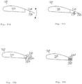
- Fig. 20
- eine Draufsicht auf ein erfindungsgemäßes Rotorblatt;
- Fig. 21
- eine Draufsicht auf den vorderen Teil eines erfindungsgemäßen Rotorblattes;
- Fig. 22
- eine vereinfachte Querschnitts-Darstellung einer ersten Ausführungsform eines erfindungsgemäßen Rotorblattes;
- Fig. 23
- eine vereinfachte Querschnitts-Darstellung einer zweiten Ausführungsform eines erfindungsgemäßen Rotorblattes;
- Fig. 24a,24b
- eine vereinfachte Querschnitts-Darstellung einer dritten Ausführungsform eines erfindungsgemäßen Rotorblattes;
- Fig. 25
- eine vereinfachte Querschnitts-Darstellung einer vierten Ausführungsform eines erfindungsgemäßen Rotorblattes;
- Fig. 26
- eine vereinfachte Querschnitts-Darstellung einer fünften Ausführungsform eines erfindungsgemäßen Rotorblattes;
- Fig. 27a,27b
- vereinfachte Querschnitts-Darstellungen einer sechsten Ausführungsform eines erfindungsgemäßen Rotorblattes;
- Fig. 28
- eine Draufsicht auf eine Konstruktionsvariante eines erfindungsgemäßen Rotorblattes; und
- Fig. 29-33
- weitere vorteilhafte Ausführungsbeispiele der Erfindung.
- Fig. 20
- a plan view of a rotor blade according to the invention;
- Fig. 21
- a plan view of the front part of a rotor blade according to the invention;
- Fig. 22
- a simplified cross-sectional view of a first embodiment of a rotor blade according to the invention;
- Fig. 23
- a simplified cross-sectional view of a second embodiment of a rotor blade according to the invention;
- 24a, 24b
- a simplified cross-sectional view of a third embodiment of a rotor blade according to the invention;
- Fig. 25
- a simplified cross-sectional view of a fourth embodiment of a rotor blade according to the invention;
- Fig. 26
- a simplified cross-sectional view of a fifth embodiment of a rotor blade according to the invention;
- 27a, 27b
- simplified cross-sectional representations of a sixth embodiment of a rotor blade according to the invention;
- Fig. 28
- a plan view of a design variant of a rotor blade according to the invention; and
- Fig. 29-33
- further advantageous embodiments of the invention.
In
Der feste Teil des Rotorblattes 100, dessen Oberfläche unverändert bleibt, ist in
Durch eine geeignete Wahl des Fülldruckes ergibt sich eine solche Stabilität dieses Teils des Rotorblattes 100, dass er bei normalen Windverhältnissen seine normale Wirkung entfaltet. In einer Extremwind-Situation ist der Winddruck auf diesen Teil des Rotorblattes 100 jedoch größer, so dass dann der äußere Druck größer als der Innendruck ist, und somit kommt es zu einer Verformung des Rotorblattes im Bereich des Hinterkastens 140 und das Rotorblatt gibt dem äußeren Winddruck nach. Dadurch wird die Angriffsfläche für diesen Extremwind geringer und damit die Lasten auf die nachfolgende Konstruktion kleiner. Ergänzend sei ausgeführt, dass dieser Teil des Hinterkastens (in dem das Füllmedium untergebracht ist), z.B. beim Überschreiten einer vorgegebenen Windgeschwindigkeit aktiv entleert werden kann, um die Oberfläche des Rotorblattes zu verkleinern. Diese aktive Entleerung hat den Vorteil, dass die Form des Rotorblattes jederzeit definiert ist, während bei einem Nachgeben des Hinterkastens infolge äußeren Druckes unbestimmte Situationen auftreten könnten.A suitable choice of the filling pressure results in such stability of this part of the
Um Beschädigungen insbesondere des Behälters 160 zu vermeiden, kann z.B. ein (nicht dargestelltes) Überdruckventil vorgesehen sein, durch welches ein sich im Behälter 160 bildender Überdruck entweichen kann.In order to avoid damage to the
Durch die Verwendung eines Kompressors 170 kann der für den Normalbetrieb erforderliche Druck wieder hergestellt werden. Werden weiterhin (ebenfalls nicht dargestellte) steuerbare Ventile und/oder Drucksensoren vorgesehen, kann der Fülldruck in dem Behälter 160 auch bei Schwankungen des Winddruckes nachgeführt werden, um so stets optimale Betriebsbedingungen beizubehalten.By using a
Zur Verringerung der aerodynamisch wirksamen Fläche kann dieses Flächenelement 240 in der Richtung des Pfeiles verschoben werden. Dieses Verschieben kann z.B. hydraulisch, nämlich mit entsprechenden Hydraulikzylindern, pneumatisch, mit Pneumatikzylindern, durch Elektroantriebe oder auf andere geeignete Weise erfolgen. Dazu müssen natürlich entsprechende (jedoch aus Gründen der Übersichtlichkeit in der Figur nicht dargestellte) Pumpen, Kompressoren oder Antriebe (Aktuatoren) vorgesehen sein.To reduce the aerodynamically effective area, this
Dabei kann dieses Verschieben in den vorderen Bereich hinein erfolgen, so dass die Oberfläche des vorderen Bereiches 110 das Flächenelement 240 überdeckt. Alternativ kann die Verschiebung auch auf der Oberfläche des vorderen Bereiches 110 erfolgen, so dass das Flächenelement 240 seinerseits den entsprechenden Teil der Oberfläche des vorderen Bereiches 110 überdeckt. In beiden Fällen ergibt sich eine Verringerung der aerodynamisch wirksamen Oberfläche des Rotorblattes 100.This shifting can take place into the front area so that the surface of the
Eine dritte Ausführungsform der vorliegenden Erfindung ist in den
In
In dieser abgewickelten Situation ist das verformbare Material 180 einerseits an dem Wickelkern 210 und andererseits an den in der Figur nach rechts weisenden Enden der Faltarme 300 befestigt. Diese Enden der Faltarme 300 können wiederum durch einen nicht dargestellten Steg verbunden sein, um einerseits eine höhere Festigkeit der Konstruktion zu erreichen und andererseits das verformbare Material zu fixieren.In this developed situation, the
Um ein Nachgeben des verformbaren Materials 180 zwischen dem Wickelkern 210 und den äußeren Enden der Faltarme 300 zu verhindern, kann unterhalb des verformbaren Materials 180 eine (nicht dargestellte) scherengitterartige Vorrichtung vorgesehen sein, die synchron mit den Faltarmen 30 betätigt wird und das verformbare Material 180 im ausgefahrenen Zustand stützt.In order to prevent the
Ein Verringern der wirksamen Oberfläche verläuft in umgekehrter Weise; die Faltarme 300 und das (nicht dargestellte) Scherengitter werden eingefahren (gefaltet) und gleichzeitig wird das verformbare Material 180 auf dem Wickelkern 210 aufgewickelt, so dass sich schließlich wieder der in
In einer in
Dabei wird das Flächenelement 240 von einer Druckfeder 280 gestützt, die zwischen dem Flächenelement 240 und der Tragkonstruktion des vorderen Bereiches 110 angeordnet ist.The
Im Normalbetrieb stützt diese Druckfeder 280 das Flächenelement 240 so, dass es die gewünschte Position beibehält. Ergibt sich nun jenseits der normalen Betriebsbedingungen ein Winddruck auf der Oberseite des Rotorblattes 100, steigt der Druck auf die Oberfläche des Flächenelementes 240 und überwindet die Kraft der Feder 280, so dass das Flächenelement 240 in der
Alternativ zu der Feder 280 können natürlich entsprechende teleskopische Elemente wie hydraulische oder pneumatische Vorrichtungen oder mechanische Vorrichtungen zur aktiven Verstellung des Flächenelements gebildet sein, z.B. können Gewindestangen und Schneckenantrieb o.ä. verwendet werden, um das Flächenelement 240 in einer ersten vorgegebenen Position zu halten oder in eine zweite vorgegebene Position zu verfahren. Für die Betätigung dieser Stellglieder müssen natürlich entsprechende Pumpen, Kompressoren oder Antriebe vorgesehen sein, die in dieser Figur wiederum zur Verbesserung der Übersichtlichkeit nicht dargestellt sind.As an alternative to the
Ebenso kann wiederum die Windlast erfasst werden, die auf das Flächenelement 240 einwirkt und abhängig von dieser erfassten Windlast kann das Flächenelement 240 um die Schwenkachse herum geschwenkt werden, um eine für die momentanen Betriebsbedingungen optimale Einstellung vorzunehmen.Likewise, the wind load which acts on the
Zur Verringerung dieser Oberfläche wird nun die Schwenkachse 220 mit dem daran befestigten Flächenelement 240 um ihre Längsachse derart gedreht, dass sich das äußere Ende des Flächenelementes 240 in einer der beiden durch den Doppelpfeil gezeigten Richtungen bewegt. Dies führt wiederum zu einer Verringerung der aerodynamisch wirksamen Oberfläche des Rotorblattes 100 und damit einhergehend zu einer Veränderung der Windlast auf das Rotorblatt 100 und alle nachfolgenden Komponenten der Windenergieanlage.To reduce this surface, the
Eine Variante der in
Jede der Lamellen 260 ist auf einer eigenen Schwenkachse angeordnet. Jede dieser Schwenkachsen 280 ist um ihre eigene Längsachse drehbar und gestattet so durch ein Drehen der Schwenkachse 280 um die Längsachse ein Verschwenken der Lamellen 260.Each of the
Eine solche Anordnung wird erreicht, indem neben einer Drehung der Schwenkachsen 280 um ihre Längsachsen außerdem der Abstand zwischen der in der Figur linken Schwenkachse 280 und dem vorderen Bereich 110 des Rotorblattes 100 einerseits und zwischen den Schwenkachsen 280 untereinander andererseits verringert wird.Such an arrangement is achieved in that, in addition to a rotation of the pivot axes 280 about their longitudinal axes, the distance between the
Sofern in den Figuren nur eine Verlängerung der Saugseite der Oberfläche dargestellt ist, kann natürlich alternativ oder ergänzend die Oberfläche der Druckseite entsprechend verändert werden.If only an extension of the suction side of the surface is shown in the figures, the surface of the pressure side can, of course, alternatively or additionally be changed accordingly.
Wird eine Windenergieanlage mit den vorbeschriebenen Rotorblättern ausgestattet, so ist es möglich, dass bei Auftreten einer Extremwind-Situation nicht nur die große Windstärke festgestellt wird, was mittels Windgeschwindigkeitsmessgeräten erfolgen kann, sondern dass auch durch eine entsprechende Steuerung die Größe der Oberfläche des Rotorblattes dann deutlich verringert wird. Wie in
Die Steuerung ist bevorzugt computergestützt und sorgt im Bedarfsfall für die jeweils optimal eingestellte Oberflächengröße des Rotorblattes.The controller is preferably computer-aided and, if necessary, ensures the optimally set surface size of the rotor blade.
Die weiteren
Die
Claims (16)
- Wind power system with the least one rotor blade (100) that is mounted on a rotor hub, as well as with a hub fairing, characterized by the fact that a rotor blade section (30) is realized on the outer side of the hub fairing and rigidly connected to it, wherein this section of the rotor blade does not form an integral part of the rotor blade of the wind power system and that the rotor blade has its maximum profile depth in the root region, namely in the region near the hub, and is realized in two parts, wherein a partition line is oriented in the longitudinal direction of the rotor blade and that the profile of the rotor blade section (30) realized on the hub fairing essentially corresponds to the profile of the rotor blade in the region near the hub.
- Wind power system according to Claim 1, characterized by the fact that the cross section of the rotor blade is described by a skeleton line, the maximum camber of which lies between 50° and 70°, preferably between 60° and 65°.
- Wind power system according to Claim 2, characterized by the fact that the maximum camber is approximately 3%-10%, preferably about 4%-7%.
- Wind power system according to one of the preceding claims, characterized by the fact that this cross section is preferably realized in the lower third of the rotor blade that is located adjacent to the rotor blade mount.
- Wind power system according to one of the preceding claims, characterized by the fact that the rotor blade has a pressure side and a suction side, wherein the pressure side contains a section with a concave camber and a nearly straight section is realized on the suction side.
- Wind power system according to Claim 5, characterized by the fact that the section of the rotor blade realized on the hub fairing is fixed in position and is essentially aligned in such a way that it lies directly underneath the region of the rotor blade near the hub if the wind velocity is below the nominal wind velocity and the rotor blade is adjusted to the position for the nominal wind velocity.
- Wind power system according to Claim 6, wherein the wind power system comprises a rotor with at least one rotor blade, the maximum profile depth of which lies in the region of the rotor blade hub, wherein the ratio between the profile depth and the rotor diameter assumes a value that lies between approximately 0.04 and 0.1, preferably between 0.055 and 0.7, e.g., 0.061.
- Wind power system according to Claim 7, with a power house that accommodates a generator and a rotor connected to the generator, wherein the rotor comprises at least two rotor blades, wherein the rotor contains a hub that is provided with a fairing (spinner), and wherein the ratio between the profile depth of the rotor blade and the diameter of the spinner is greater than 0.4, preferably between 0.5 and 1.
- Wind power system according to one of the preceding claims, with a rotor that preferably comprises more than one rotor blade, wherein the rotor blade has a trapezoidal shape that more or less resembles the optimal aerodynamic shape, wherein the rotor blade has its maximum width in the region of the rotor blade root, and wherein the edge of the rotor blade root that faces the nacelle of the wind power system is realized in such a way that it essentially follows the outside contours of the nacelle (in the longitudinal direction) .
- Wind power system according to Claim 9, characterized by the fact that the lower edge of the rotor blade that faces the nacelle lies nearly parallel to the outside contour of the nacelle in the root region when the rotor blade is turned into the feathered pitch position.
- Wind power system according to Claim 10, characterized by the fact that the distance between the lower edge of the rotor blade that faces the nacelle and the outside contours of the nacelle is less than 50 cm, preferably less than 20 cm, in the feathered pitch position.
- Wind power system according to one of the preceding claims, characterized by the fact that the rotor blade is tilted out of the principal plane of the rotor blade in the root region.
- Wind power system according to one of the preceding claims, characterized by the fact that the rotor blade is realized in two parts in the root region, wherein the partition line is oriented in the longitudinal direction of the rotor blade.
- Wind power system according to Claim 13, characterized by the fact that the two parts of the rotor blade are not assembled until the installation of the rotor blade into the wind power system.
- Wind power system according to Claims 13 and 14, characterized by the fact that the parts of the rotor blade remain separated during transport.
- Wind power system according to one of the preceding claims, characterized by the fact that the wind power system contains at least one rotor blade that is characterized by a suction side and a pressure side, wherein the ratio between the length of the suction side and the length of the pressure side is smaller than 1.2, preferably smaller than 1.1, particularly between 1 and 1.03.
Priority Applications (1)
| Application Number | Priority Date | Filing Date | Title |
|---|---|---|---|
| EP10183781.3A EP2258943A3 (en) | 2003-04-28 | 2004-03-29 | Wind turbine blade profile |
Applications Claiming Priority (2)
| Application Number | Priority Date | Filing Date | Title |
|---|---|---|---|
| DE10319246A DE10319246A1 (en) | 2003-04-28 | 2003-04-28 | Rotor blade of a wind turbine |
| PCT/EP2004/003294 WO2004097215A1 (en) | 2003-04-28 | 2004-03-29 | Rotor blade of a wind energy facility |
Related Child Applications (1)
| Application Number | Title | Priority Date | Filing Date |
|---|---|---|---|
| EP10183781.3A Division-Into EP2258943A3 (en) | 2003-04-28 | 2004-03-29 | Wind turbine blade profile |
Publications (2)
| Publication Number | Publication Date |
|---|---|
| EP1620646A1 EP1620646A1 (en) | 2006-02-01 |
| EP1620646B1 true EP1620646B1 (en) | 2020-01-22 |
Family
ID=33393962
Family Applications (2)
| Application Number | Title | Priority Date | Filing Date |
|---|---|---|---|
| EP04723988.4A Expired - Lifetime EP1620646B1 (en) | 2003-04-28 | 2004-03-29 | Rotor blade of a wind energy facility |
| EP10183781.3A Withdrawn EP2258943A3 (en) | 2003-04-28 | 2004-03-29 | Wind turbine blade profile |
Family Applications After (1)
| Application Number | Title | Priority Date | Filing Date |
|---|---|---|---|
| EP10183781.3A Withdrawn EP2258943A3 (en) | 2003-04-28 | 2004-03-29 | Wind turbine blade profile |
Country Status (17)
| Country | Link |
|---|---|
| US (1) | US7946803B2 (en) |
| EP (2) | EP1620646B1 (en) |
| JP (2) | JP4504971B2 (en) |
| KR (1) | KR100812796B1 (en) |
| CN (1) | CN100366893C (en) |
| AR (1) | AR046912A1 (en) |
| AU (1) | AU2004234487B2 (en) |
| BR (1) | BRPI0409782B1 (en) |
| CA (2) | CA2683764C (en) |
| DE (1) | DE10319246A1 (en) |
| DK (1) | DK1620646T3 (en) |
| ES (1) | ES2778830T3 (en) |
| NO (1) | NO20055599L (en) |
| NZ (1) | NZ543574A (en) |
| PT (1) | PT1620646T (en) |
| WO (1) | WO2004097215A1 (en) |
| ZA (1) | ZA200508323B (en) |
Families Citing this family (71)
| Publication number | Priority date | Publication date | Assignee | Title |
|---|---|---|---|---|
| AU2003237707B2 (en) | 2002-06-05 | 2008-01-10 | Aloys Wobben | Rotor blade for a wind power plant |
| US8147209B2 (en) | 2005-02-22 | 2012-04-03 | Vestas Wind Systems A/S | Wind turbine blade |
| EP1845258A1 (en) | 2006-04-10 | 2007-10-17 | Siemens Aktiengesellschaft | Wind turbine rotor blade |
| DE102006017897B4 (en) * | 2006-04-13 | 2008-03-13 | Repower Systems Ag | Rotor blade of a wind turbine |
| ES2294927B1 (en) * | 2006-05-31 | 2009-02-16 | Gamesa Eolica, S.A. | AIRLINER SHOVEL WITH DIVERGING OUTPUT EDGE. |
| KR100926792B1 (en) * | 2006-12-29 | 2009-11-13 | 한국에너지기술연구원 | Tip airfoil of wind power generator for stall control and steady speed operation in low wind speed with improved contamination dullness |
| US8197218B2 (en) * | 2007-11-08 | 2012-06-12 | Alliance For Sustainable Energy, Llc | Quiet airfoils for small and large wind turbines |
| US20090148285A1 (en) * | 2007-12-06 | 2009-06-11 | General Electric Company | Multi-section wind turbine rotor blades and wind turbines incorporating same |
| US20090148291A1 (en) * | 2007-12-06 | 2009-06-11 | General Electric Company | Multi-section wind turbine rotor blades and wind turbines incorporating same |
| EP2078851A1 (en) | 2008-01-14 | 2009-07-15 | Lm Glasfiber A/S | Wind turbine blade and hub assembly |
| DE102008026474A1 (en) | 2008-06-03 | 2009-12-10 | Mickeler, Siegfried, Prof. Dr.-Ing. | Rotor blade for a wind turbine and wind turbine |
| CN102187092B (en) * | 2008-09-19 | 2015-05-20 | 考特能源有限公司 | Wind turbine with low induction tips |
| DK2350452T4 (en) * | 2008-10-14 | 2020-08-31 | Vestas Wind Sys As | Wind turbine blade with device for changing the aerodynamic surface or shape |
| CA2741479A1 (en) * | 2008-10-22 | 2010-04-29 | Vec Industries, L.L.C. | Wind turbine blade and method for manufacturing thereof |
| US7837442B2 (en) | 2008-12-03 | 2010-11-23 | General Electric Company | Root sleeve for wind turbine blade |
| US7988421B2 (en) | 2009-03-31 | 2011-08-02 | General Electric Company | Retrofit sleeve for wind turbine blade |
| DE102009002501A1 (en) | 2009-04-20 | 2010-10-28 | Wobben, Aloys | Rotor blade element and manufacturing process |
| US8241000B2 (en) * | 2009-06-16 | 2012-08-14 | Heartland Energy Solutions, LLC. | Wind turbine rotor blade and airfoil section |
| US8011886B2 (en) | 2009-06-30 | 2011-09-06 | General Electric Company | Method and apparatus for increasing lift on wind turbine blade |
| US9270150B2 (en) | 2009-12-16 | 2016-02-23 | Clear Path Energy, Llc | Axial gap rotating electrical machine |
| US8197208B2 (en) * | 2009-12-16 | 2012-06-12 | Clear Path Energy, Llc | Floating underwater support structure |
| DK2366891T3 (en) | 2010-03-18 | 2014-10-27 | Nordex Energy Gmbh | Wind power installation rotor blade- |
| DK2366892T3 (en) * | 2010-03-18 | 2014-11-10 | Nordex Energy Gmbh | Wind power installation rotor blade- |
| DK3835571T3 (en) * | 2010-07-16 | 2023-12-04 | Lm Wind Power As | Wind turbine blade with narrow shoulder and relatively thick airfoil profiles |
| DE102010040596A1 (en) | 2010-09-10 | 2012-03-15 | Aloys Wobben | Removable rotor blade tip |
| CN102407779B (en) * | 2010-09-21 | 2014-10-01 | 周鹏 | Power generation device for power motor vehicle |
| KR20130041263A (en) * | 2010-10-22 | 2013-04-24 | 미츠비시 쥬고교 가부시키가이샤 | Wind turbine, wind power generation device provided therewith, and wind turbine design method |
| JP5479300B2 (en) * | 2010-10-22 | 2014-04-23 | 三菱重工業株式会社 | Wind turbine blade, wind power generator equipped with the wind turbine blade, and wind turbine blade design method |
| CN102003333B (en) * | 2010-12-21 | 2012-01-11 | 中国科学院工程热物理研究所 | Wind turbine blade with de-noising function |
| DK2479423T3 (en) | 2011-01-24 | 2018-05-28 | Siemens Ag | Wind turbine rotor blade element |
| JP5479388B2 (en) * | 2011-02-28 | 2014-04-23 | 三菱重工業株式会社 | Wind turbine blade and wind power generator equipped with the same |
| GB201109412D0 (en) * | 2011-06-03 | 2011-07-20 | Blade Dynamics Ltd | A wind turbine rotor |
| KR20130064087A (en) | 2011-10-12 | 2013-06-17 | 미츠비시 쥬고교 가부시키가이샤 | Wind turbine blade, windturbine generator with the same and method of designing the same |
| DE102012209935A1 (en) * | 2011-12-08 | 2013-06-13 | Wobben Properties Gmbh | Rear box, rotor blade with rear box and wind turbine with such rotor blade |
| EP2834517B1 (en) | 2012-03-13 | 2020-05-06 | Wobben Properties GmbH | Twisted blade root |
| NL2009286C2 (en) | 2012-08-06 | 2014-02-10 | Stichting Energie | Swallow tail airfoil. |
| US11136958B2 (en) | 2012-08-06 | 2021-10-05 | Nederlandse Organisatie Voor Toegepast-Natuurwetenschappelijk Onderzoek Tno | Swallow tail airfoil |
| EP2713044B2 (en) * | 2012-09-28 | 2022-12-07 | Siemens Gamesa Renewable Energy A/S | Wind turbine rotor blade |
| ITMI20121797A1 (en) | 2012-10-23 | 2014-04-24 | Wilic Sarl | AERODYNAMIC APPENDIX FOR A SHOVEL OF AN AEROGENERATOR AND SHOVEL OF AEROGENERATOR PROVIDED WITH THIS AERODYNAMIC APPENDIX |
| KR101331961B1 (en) | 2012-10-23 | 2013-11-22 | 한국에너지기술연구원 | Blade airfoil for wind turbine generator having trailing edge shape which possible inserting of aerodynamic control unit |
| CN103133273B (en) * | 2013-03-26 | 2015-12-02 | 国电联合动力技术有限公司 | A kind of thin airfoil type blade of large fan |
| CN103244359B (en) * | 2013-05-30 | 2016-04-13 | 国电联合动力技术有限公司 | A kind of intermediate gauge airfoil fan of large fan |
| CN103321857B (en) * | 2013-07-08 | 2015-05-06 | 国电联合动力技术有限公司 | Large-thickness blunt-trailing-edge airfoil-shaped blade of large-scale wind turbine |
| KR101466076B1 (en) * | 2013-08-22 | 2014-11-28 | 삼성중공업 주식회사 | Blade |
| DE102013217128A1 (en) | 2013-08-28 | 2015-03-05 | Wobben Properties Gmbh | Rotor blade element for a wind energy plant, rotor blade, and a manufacturing method therefor and wind turbine with rotor blade |
| CN103711655B (en) * | 2013-12-26 | 2016-04-06 | 中国科学院工程热物理研究所 | The blunt trailing edge pneumatic equipment blades made of a kind of heavy thickness |
| EP3115599A4 (en) * | 2014-03-04 | 2017-03-29 | The Chugoku Electric Power Co., Inc. | Wind power generation device |
| WO2015132884A1 (en) * | 2014-03-04 | 2015-09-11 | 中国電力株式会社 | Wind power generation device |
| ITBZ20140002U1 (en) | 2014-03-13 | 2015-09-13 | Frassinelli Ernesto | WIND FOLDER WITH ADAPTIVE PROFILE ABLE TO MODIFY ITS STRUCTURE ON THE BASIS OF THE AERODYNAMIC PRESSURE THAT INVESTS IT, THE CLIMATE AND METEOROLOGICAL CHARACTERISTICS OF THE INSTALLATION SITE AND, COMPOSING A SINGLE ROTOR WITH ONE OR MORE ELEMENTS, WITH A MICRO-WIND GENERATOR WITH ROTATION AXIS PARALLEO AT THE AERODYNAMIC FLOW. |
| USD829172S1 (en) * | 2014-09-15 | 2018-09-25 | Raymond Cooper | Horizontal axis wind turbine with a flow-through hub, a nacelle, and a tandem blade configuration |
| USD801927S1 (en) * | 2014-09-15 | 2017-11-07 | II Raymond Cooper | Horizontal axis wind turbine with flow-through hub and nacelle and tandem blade configuration |
| US11125205B2 (en) * | 2015-09-14 | 2021-09-21 | General Electric Company | Systems and methods for joining blade components of rotor blades |
| DE102015116634A1 (en) * | 2015-10-01 | 2017-04-06 | Wobben Properties Gmbh | Wind turbine rotor blade and wind turbine |
| DE102015220672A1 (en) | 2015-10-22 | 2017-04-27 | Wobben Properties Gmbh | Multilayer composite component |
| DE102016213206A1 (en) | 2016-07-19 | 2018-01-25 | Wobben Properties Gmbh | Multilayer composite component |
| CN105626373A (en) * | 2016-03-04 | 2016-06-01 | 云南电网有限责任公司电力科学研究院 | Rotary vane of wind turbine |
| DE102016121554A1 (en) | 2016-11-10 | 2018-05-17 | Wobben Properties Gmbh | Multilayer composite component |
| CN106741857A (en) * | 2017-03-02 | 2017-05-31 | 南京那尔朴电子有限公司 | A kind of propeller that can be adjusted with thrust |
| US11885297B2 (en) | 2017-05-10 | 2024-01-30 | Gerald L. Barber | Transitioning wind turbine |
| US10788016B2 (en) | 2017-05-10 | 2020-09-29 | Gerald L. Barber | Transitioning wind turbine |
| DE102017112742A1 (en) * | 2017-06-09 | 2018-12-13 | Wobben Properties Gmbh | Rotor blade for a wind turbine and wind turbine |
| DE102017124861A1 (en) * | 2017-10-24 | 2019-04-25 | Wobben Properties Gmbh | Rotor blade of a wind turbine and method for its design |
| EP3790798A4 (en) | 2018-05-10 | 2022-01-19 | Joby Aero, Inc. | Electric tiltrotor aircraft |
| WO2020009871A1 (en) | 2018-07-02 | 2020-01-09 | Joby Aero, Inc. | System and method for airspeed determination |
| US11323214B2 (en) | 2018-09-17 | 2022-05-03 | Joby Aero, Inc. | Aircraft control system |
| JP7401545B2 (en) | 2018-12-07 | 2023-12-19 | ジョビー エアロ インク | Rotor blades and their design methods |
| WO2020180373A2 (en) | 2018-12-07 | 2020-09-10 | Joby Aero, Inc. | Aircraft control system and method |
| CN116646641A (en) | 2019-04-23 | 2023-08-25 | 杰欧比飞行有限公司 | Battery thermal management system and method |
| DE102019119027B4 (en) * | 2019-07-12 | 2022-04-28 | Wobben Properties Gmbh | Rotor blade and wind turbine |
| CN112065651B (en) * | 2020-07-21 | 2021-12-14 | 兰州理工大学 | Airfoil for wind turbine blade layer of wind generating set |
| DE102022104017A1 (en) | 2022-02-21 | 2023-08-24 | Wobben Properties Gmbh | Rotor blade of a wind turbine |
Family Cites Families (70)
| Publication number | Priority date | Publication date | Assignee | Title |
|---|---|---|---|---|
| US1403069A (en) * | 1921-08-12 | 1922-01-10 | Burne Edward Lancaster | Means for regulating the speed of wind motors |
| US2622686A (en) * | 1942-07-21 | 1952-12-23 | Chevreau Rene Louis Pier Marie | Wind motor |
| US2428936A (en) * | 1943-09-10 | 1947-10-14 | Goodrich Co B F | Aerodynamic brake |
| US2485543A (en) * | 1943-10-19 | 1949-10-25 | Andreau Jean Edouard | Power plant |
| US2465007A (en) * | 1944-01-05 | 1949-03-22 | Gen Motors Corp | Aircraft propeller |
| US2400388A (en) * | 1944-03-17 | 1946-05-14 | Goodrich Co B F | Aerodynamic brake |
| US2442783A (en) * | 1944-07-01 | 1948-06-08 | Us Sec War | Turbine rotor |
| FR908631A (en) * | 1944-08-01 | 1946-04-15 | Aero-engine improvements | |
| US2453403A (en) * | 1946-07-03 | 1948-11-09 | Charles E Bogardus | Windbreaker for parked aircraft |
| US2616509A (en) * | 1946-11-29 | 1952-11-04 | Thomas Wilfred | Pneumatic airfoil |
| US2934150A (en) * | 1955-12-21 | 1960-04-26 | United Aircraft Corp | Pressure-contoured spinner |
| US3184187A (en) * | 1963-05-10 | 1965-05-18 | Isaac Peter | Retractable airfoils and hydrofoils |
| US3463420A (en) * | 1968-02-28 | 1969-08-26 | North American Rockwell | Inflatable wing |
| US3987984A (en) * | 1973-04-09 | 1976-10-26 | Albert George Fischer | Semi-rigid aircraft wing |
| US3874816A (en) * | 1973-10-23 | 1975-04-01 | Thomas E Sweeney | Windmill blade |
| FR2290585A1 (en) | 1974-11-07 | 1976-06-04 | Morin Bernard | Blade with variable profile for windmill rotor - has profile controlled by wind force and rotor speed |
| SU577300A1 (en) | 1975-12-09 | 1977-10-25 | Свердловский Ордена Трудового Красного Знамени Горный Институт Им. В.В.Вахрушева | Turbine machine blade |
| DE2829716A1 (en) * | 1977-07-07 | 1979-01-25 | Univ Gakko Hojin Tokai | WIND POWER MACHINE WITH VERTICAL AXIS |
| JPS5928754B2 (en) | 1979-05-18 | 1984-07-16 | 富治 高山 | Vertical axis wind turbine blade |
| US4274011A (en) * | 1980-03-14 | 1981-06-16 | Marvin Garfinkle | Wind turbine for marine propulsion |
| US4408958A (en) * | 1980-12-23 | 1983-10-11 | The Bendix Corporation | Wind turbine blade |
| DE3113079C2 (en) * | 1981-04-01 | 1985-11-21 | Messerschmitt-Bölkow-Blohm GmbH, 8000 München | Large aerodynamic wing and process for its manufacture |
| DE3126677A1 (en) | 1981-07-07 | 1983-01-20 | Erno-Raumfahrttechnik Gmbh, 2800 Bremen | Rotor blade design for high-speed rotors |
| US4519746A (en) * | 1981-07-24 | 1985-05-28 | United Technologies Corporation | Airfoil blade |
| US4419053A (en) * | 1981-11-20 | 1983-12-06 | Fairchild Swearingen Corporation | Propeller spinner |
| US4498017A (en) * | 1982-12-16 | 1985-02-05 | Parkins William E | Generating power from wind |
| US4692095A (en) * | 1984-04-26 | 1987-09-08 | Sir Henry Lawson-Tancred, Sons & Co. Ltd. | Wind turbine blades |
| US4699568A (en) * | 1984-06-25 | 1987-10-13 | Hartzell Propeller Inc. | Aircraft propeller with improved spinner assembly |
| US4613760A (en) * | 1984-09-12 | 1986-09-23 | The English Electric Company Limited | Power generating equipment |
| CH666728A5 (en) * | 1985-01-18 | 1988-08-15 | Escher Wyss Gmbh | ROTOR OF A WIND TURBINE. |
| JPS61192864A (en) * | 1985-02-20 | 1986-08-27 | Yamaha Motor Co Ltd | Rotor blade structure of wind mill |
| FR2587675A1 (en) | 1985-09-24 | 1987-03-27 | Dumortier Paul | Ailerons having self-deforming reversible profiles |
| FR2590229B1 (en) * | 1985-11-19 | 1988-01-29 | Onera (Off Nat Aerospatiale) | IMPROVEMENTS ON AIR PROPELLERS WITH REGARD TO THE PROFILE OF THEIR BLADES |
| DE3875640D1 (en) | 1987-03-14 | 1992-12-10 | M T B Manoevriertechnisches Bu | FLOW BODY FLOWED BY AIR OR WATER. |
| US4830574A (en) * | 1988-02-29 | 1989-05-16 | United Technologies Corporation | Airfoiled blade |
| SU1539378A1 (en) | 1988-03-29 | 1990-01-30 | Институт Электродинамики Ан Усср | Blade of wind motor |
| US4976587A (en) * | 1988-07-20 | 1990-12-11 | Dwr Wind Technologies Inc. | Composite wind turbine rotor blade and method for making same |
| GB8829836D0 (en) | 1988-12-21 | 1989-02-15 | British Aerospace | Wing flap hoot suppression |
| GB2227286A (en) * | 1989-01-17 | 1990-07-25 | Howden Wind Turbines Limited | Control of a wind turbine and adjustable blade therefor |
| DE3913505A1 (en) * | 1989-04-25 | 1989-11-16 | Astrid Holzem | WING WITH AERODYNAMIC BRAKE FOR WIND ENGINES |
| DE4002972C2 (en) | 1990-02-01 | 1994-06-16 | Guenter Waldherr | Wing with changeable profile, especially for use as a sail |
| JPH05189146A (en) | 1992-01-16 | 1993-07-30 | Hiroo Yasui | Track ball-mouse |
| US5527151A (en) * | 1992-03-04 | 1996-06-18 | Northern Power Systems, Inc. | Advanced wind turbine with lift-destroying aileron for shutdown |
| GB2265672B (en) * | 1992-03-18 | 1995-11-22 | Advanced Wind Turbines Inc | Wind turbines |
| US5320491A (en) * | 1992-07-09 | 1994-06-14 | Northern Power Systems, Inc. | Wind turbine rotor aileron |
| US5417548A (en) * | 1994-01-14 | 1995-05-23 | Midwest Research Institute | Root region airfoil for wind turbine |
| US5562420A (en) * | 1994-03-14 | 1996-10-08 | Midwest Research Institute | Airfoils for wind turbine |
| DE4428731A1 (en) | 1994-08-15 | 1996-02-22 | Infan Gmbh Ingenieurgesellscha | Variable length rotor blade for wind power systems |
| DE4435606A1 (en) | 1994-10-06 | 1996-04-11 | Manfred Dipl Ing Maibom | Size adjustable blade for wind power rotor |
| US5570859A (en) * | 1995-01-09 | 1996-11-05 | Quandt; Gene A. | Aerodynamic braking device |
| US5570997A (en) * | 1995-07-17 | 1996-11-05 | Pratt; Charles W. | Horizontal windmill with folding blades |
| GB2311978A (en) | 1996-04-10 | 1997-10-15 | Robert Pyatt | Adjustable wing |
| DE19719221C1 (en) | 1997-05-07 | 1998-10-29 | Roland Stelzer | Rotor blade for wind generator |
| US6420795B1 (en) * | 1998-08-08 | 2002-07-16 | Zond Energy Systems, Inc. | Variable speed wind turbine generator |
| US6068446A (en) * | 1997-11-20 | 2000-05-30 | Midwest Research Institute | Airfoils for wind turbine |
| US6015115A (en) * | 1998-03-25 | 2000-01-18 | Lockheed Martin Corporation | Inflatable structures to control aircraft |
| US6133716A (en) * | 1998-10-23 | 2000-10-17 | Statordyne, Inc. | High-efficiency high-power uninterrupted power system |
| ES2178903B1 (en) | 1999-05-31 | 2004-03-16 | Torres Martinez M | SHOVEL FOR AEROGENERATOR. |
| DE19962989B4 (en) * | 1999-12-24 | 2006-04-13 | Wobben, Aloys, Dipl.-Ing. | Rotor blade for wind turbines |
| DE10003385A1 (en) | 2000-01-26 | 2001-08-02 | Aloys Wobben | Wind turbine |
| US6503058B1 (en) * | 2000-05-01 | 2003-01-07 | Zond Energy Systems, Inc. | Air foil configuration for wind turbine |
| US6523781B2 (en) * | 2000-08-30 | 2003-02-25 | Gary Dean Ragner | Axial-mode linear wind-turbine |
| US6951443B1 (en) * | 2000-09-08 | 2005-10-04 | General Electric Company | Wind turbine ring/shroud drive system |
| WO2002051730A2 (en) * | 2000-12-23 | 2002-07-04 | Aloys Wobben | Rotor blade for a wind power installation |
| US6682302B2 (en) * | 2001-03-20 | 2004-01-27 | James D. Noble | Turbine apparatus and method |
| US6465902B1 (en) * | 2001-04-18 | 2002-10-15 | The United States Of America As Represented By The Secretary Of The Navy | Controllable camber windmill blades |
| US7059833B2 (en) * | 2001-11-26 | 2006-06-13 | Bonus Energy A/S | Method for improvement of the efficiency of a wind turbine rotor |
| DE10307682A1 (en) * | 2002-06-05 | 2004-01-08 | Aloys Wobben | Rotor blade of a wind turbine |
| AU2003237707B2 (en) * | 2002-06-05 | 2008-01-10 | Aloys Wobben | Rotor blade for a wind power plant |
| USD584686S1 (en) * | 2007-07-23 | 2009-01-13 | Aloys Wobben | Nacelle of a wind turbine |
-
2003
- 2003-04-28 DE DE10319246A patent/DE10319246A1/en not_active Withdrawn
-
2004
- 2004-03-29 DK DK04723988.4T patent/DK1620646T3/en active
- 2004-03-29 JP JP2006504897A patent/JP4504971B2/en not_active Expired - Fee Related
- 2004-03-29 US US10/554,628 patent/US7946803B2/en active Active
- 2004-03-29 WO PCT/EP2004/003294 patent/WO2004097215A1/en active Application Filing
- 2004-03-29 KR KR1020057020515A patent/KR100812796B1/en active IP Right Grant
- 2004-03-29 BR BRPI0409782-3A patent/BRPI0409782B1/en active IP Right Grant
- 2004-03-29 NZ NZ543574A patent/NZ543574A/en unknown
- 2004-03-29 CA CA2683764A patent/CA2683764C/en not_active Expired - Fee Related
- 2004-03-29 EP EP04723988.4A patent/EP1620646B1/en not_active Expired - Lifetime
- 2004-03-29 EP EP10183781.3A patent/EP2258943A3/en not_active Withdrawn
- 2004-03-29 ES ES04723988T patent/ES2778830T3/en not_active Expired - Lifetime
- 2004-03-29 CA CA2524208A patent/CA2524208C/en not_active Expired - Fee Related
- 2004-03-29 AU AU2004234487A patent/AU2004234487B2/en not_active Ceased
- 2004-03-29 PT PT47239884T patent/PT1620646T/en unknown
- 2004-03-29 CN CNB2004800114863A patent/CN100366893C/en not_active Expired - Fee Related
- 2004-04-28 AR ARP040101437A patent/AR046912A1/en not_active Application Discontinuation
-
2005
- 2005-10-14 ZA ZA200508323A patent/ZA200508323B/en unknown
- 2005-11-25 NO NO20055599A patent/NO20055599L/en not_active Application Discontinuation
-
2009
- 2009-10-23 JP JP2009244773A patent/JP5334796B2/en not_active Expired - Fee Related
Non-Patent Citations (1)
| Title |
|---|
| "Niedrig-geschwindigkeits-profile", 1 January 1996, VIEWEG&SOHN VERLAGSGESELLSCCHAFT MBH, LENGERICH, DEUTSCHLAND, ISBN: 978-3-52-803820-5, article DIETER ALTHAUS: "Cambered Airfoils without Flaps for use in Wind Turbines", pages: 157 - 159, XP055079965 * |
Also Published As
| Publication number | Publication date |
|---|---|
| AU2004234487A1 (en) | 2004-11-11 |
| EP2258943A3 (en) | 2013-10-02 |
| KR20060017761A (en) | 2006-02-27 |
| JP2006524772A (en) | 2006-11-02 |
| AU2004234487B2 (en) | 2009-02-19 |
| CA2683764C (en) | 2013-04-30 |
| NZ543574A (en) | 2009-02-28 |
| CN1780982A (en) | 2006-05-31 |
| CA2683764A1 (en) | 2004-11-11 |
| ZA200508323B (en) | 2006-06-28 |
| ES2778830T3 (en) | 2020-08-12 |
| JP2010043650A (en) | 2010-02-25 |
| BRPI0409782B1 (en) | 2014-05-20 |
| JP5334796B2 (en) | 2013-11-06 |
| DE10319246A1 (en) | 2004-12-16 |
| CN100366893C (en) | 2008-02-06 |
| EP2258943A2 (en) | 2010-12-08 |
| CA2524208C (en) | 2012-02-28 |
| JP4504971B2 (en) | 2010-07-14 |
| US20070036657A1 (en) | 2007-02-15 |
| CA2524208A1 (en) | 2004-11-11 |
| US7946803B2 (en) | 2011-05-24 |
| WO2004097215A1 (en) | 2004-11-11 |
| KR100812796B1 (en) | 2008-03-12 |
| EP1620646A1 (en) | 2006-02-01 |
| PT1620646T (en) | 2020-04-23 |
| NO20055599L (en) | 2005-11-25 |
| BRPI0409782A (en) | 2006-05-30 |
| AR046912A1 (en) | 2006-01-04 |
| DK1620646T3 (en) | 2020-04-14 |
Similar Documents
| Publication | Publication Date | Title |
|---|---|---|
| EP1620646B1 (en) | Rotor blade of a wind energy facility | |
| EP1350027B1 (en) | Rotor blade for a wind power installation | |
| EP1514023B1 (en) | Wind power plant | |
| DE102005034078B4 (en) | In-plane sweep wind turbine blades and devices using the same and methods for their manufacture | |
| EP2280163B1 (en) | Wind power plant and rotor blade for a wind power plant | |
| EP2339171B1 (en) | Rotor blade for a wind power converter | |
| EP3008331B1 (en) | Rotor blade of a wind turbine and wind turbine | |
| EP3377759B1 (en) | Control of a wind turbine having adjustable rotor blades | |
| DE2632697A1 (en) | WIND POWER MACHINE | |
| WO2009146810A2 (en) | Rotor blade for a wind power plant and wind power plant | |
| DE102011051831A1 (en) | Rotor blade for a wind turbine with a suction side winglet | |
| EP3755899B1 (en) | Rotor blade of a wind turbine, having a splitter plate | |
| EP3330530A1 (en) | Wind turbine blade | |
| WO2001048377A1 (en) | Rotor blade for a wind power installation | |
| EP3399183B1 (en) | Rotor blade of a wind turbine | |
| EP2976524B1 (en) | Rotor blade of a wind power plant, wind power plant and method for operating a wind power plant | |
| DE10152449A1 (en) | Rotor blade for wind turbine is fitted with system for altering its surface, e.g. pivoting flap or section of rotor which can be wound up on to core | |
| AT408022B (en) | WIND TURBINE WITH VERTICAL OR INCLINED AXLE AND DRIVE EXPLOITATION | |
| EP3981981A1 (en) | Rotor blade for a wind turbine, wind turbine and method for designing a rotor blade | |
| EP3698041B1 (en) | Rotor blade and rotor for a wind turbine, having bearing-free pitch adjustment, and wind turbine | |
| DE10064912B4 (en) | Rotor blade for a wind energy plant | |
| DE102010041520B4 (en) | Rotor blade and method for operating a wind turbine | |
| EP3280910A1 (en) | Wind turbine rotor blade | |
| AT511895A1 (en) | WIND POWER ROTOR IN DARRIEUS-H CONSTRUCTION AND RELATED ROTOR BLADE |
Legal Events
| Date | Code | Title | Description |
|---|---|---|---|
| PUAI | Public reference made under article 153(3) epc to a published international application that has entered the european phase |
Free format text: ORIGINAL CODE: 0009012 |
|
| 17P | Request for examination filed |
Effective date: 20051128 |
|
| AK | Designated contracting states |
Kind code of ref document: A1 Designated state(s): AT BE BG CH CY CZ DE DK EE ES FI FR GB GR HU IE IT LI LU MC NL PL PT RO SE SI SK TR |
|
| AX | Request for extension of the european patent |
Extension state: LV |
|
| RAX | Requested extension states of the european patent have changed |
Extension state: LV Payment date: 20051128 |
|
| 17Q | First examination report despatched |
Effective date: 20080131 |
|
| RAX | Requested extension states of the european patent have changed |
Extension state: LV Payment date: 20051128 Extension state: LT Payment date: 20051128 |
|
| RAP1 | Party data changed (applicant data changed or rights of an application transferred) |
Owner name: WOBBEN PROPERTIES GMBH |
|
| RIN1 | Information on inventor provided before grant (corrected) |
Inventor name: WOBBEN PROPERTIES GMBH |
|
| RAP1 | Party data changed (applicant data changed or rights of an application transferred) |
Owner name: WOBBEN PROPERTIES GMBH |
|
| RIN1 | Information on inventor provided before grant (corrected) |
Inventor name: WOBBEN PROPERTIES GMBH |
|
| RIN1 | Information on inventor provided before grant (corrected) |
Inventor name: DER ERFINDER HAT AUF SEINE NENNUNG VERZICHTET. |
|
| RIN1 | Information on inventor provided before grant (corrected) |
Inventor name: WOBBEN, ALOYS |
|
| STAA | Information on the status of an ep patent application or granted ep patent |
Free format text: STATUS: EXAMINATION IS IN PROGRESS |
|
| GRAP | Despatch of communication of intention to grant a patent |
Free format text: ORIGINAL CODE: EPIDOSNIGR1 |
|
| STAA | Information on the status of an ep patent application or granted ep patent |
Free format text: STATUS: GRANT OF PATENT IS INTENDED |
|
| INTG | Intention to grant announced |
Effective date: 20190918 |
|
| GRAS | Grant fee paid |
Free format text: ORIGINAL CODE: EPIDOSNIGR3 |
|
| GRAA | (expected) grant |
Free format text: ORIGINAL CODE: 0009210 |
|
| STAA | Information on the status of an ep patent application or granted ep patent |
Free format text: STATUS: THE PATENT HAS BEEN GRANTED |
|
| REG | Reference to a national code |
Ref country code: DE Ref legal event code: R081 Ref document number: 502004015846 Country of ref document: DE Owner name: WOBBEN PROPERTIES GMBH, DE Free format text: FORMER OWNER: WOBBEN, ALOYS, 26607 AURICH, DE |
|
| AK | Designated contracting states |
Kind code of ref document: B1 Designated state(s): AT BE BG CH CY CZ DE DK EE ES FI FR GB GR HU IE IT LI LU MC NL PL PT RO SE SI SK TR |
|
| AX | Request for extension of the european patent |
Extension state: LT LV |
|
| REG | Reference to a national code |
Ref country code: GB Ref legal event code: FG4D Free format text: NOT ENGLISH |
|
| REG | Reference to a national code |
Ref country code: CH Ref legal event code: EP |
|
| REG | Reference to a national code |
Ref country code: AT Ref legal event code: REF Ref document number: 1227063 Country of ref document: AT Kind code of ref document: T Effective date: 20200215 |
|
| REG | Reference to a national code |
Ref country code: IE Ref legal event code: FG4D Free format text: LANGUAGE OF EP DOCUMENT: GERMAN |
|
| REG | Reference to a national code |
Ref country code: DE Ref legal event code: R096 Ref document number: 502004015846 Country of ref document: DE |
|
| REG | Reference to a national code |
Ref country code: DK Ref legal event code: T3 Effective date: 20200407 |
|
| REG | Reference to a national code |
Ref country code: PT Ref legal event code: SC4A Ref document number: 1620646 Country of ref document: PT Date of ref document: 20200423 Kind code of ref document: T Free format text: AVAILABILITY OF NATIONAL TRANSLATION Effective date: 20200415 |
|
| REG | Reference to a national code |
Ref country code: NL Ref legal event code: FP |
|
| PGFP | Annual fee paid to national office [announced via postgrant information from national office to epo] |
Ref country code: AT Payment date: 20200319 Year of fee payment: 17 |
|
| REG | Reference to a national code |
Ref country code: SE Ref legal event code: TRGR |
|
| REG | Reference to a national code |
Ref country code: LT Ref legal event code: MG9D |
|
| PG25 | Lapsed in a contracting state [announced via postgrant information from national office to epo] |
Ref country code: FI Free format text: LAPSE BECAUSE OF FAILURE TO SUBMIT A TRANSLATION OF THE DESCRIPTION OR TO PAY THE FEE WITHIN THE PRESCRIBED TIME-LIMIT Effective date: 20200122 |
|
| PGFP | Annual fee paid to national office [announced via postgrant information from national office to epo] |
Ref country code: ES Payment date: 20200421 Year of fee payment: 17 Ref country code: PT Payment date: 20200526 Year of fee payment: 17 |
|
| REG | Reference to a national code |
Ref country code: ES Ref legal event code: FG2A Ref document number: 2778830 Country of ref document: ES Kind code of ref document: T3 Effective date: 20200812 |
|
| PG25 | Lapsed in a contracting state [announced via postgrant information from national office to epo] |
Ref country code: GR Free format text: LAPSE BECAUSE OF FAILURE TO SUBMIT A TRANSLATION OF THE DESCRIPTION OR TO PAY THE FEE WITHIN THE PRESCRIBED TIME-LIMIT Effective date: 20200423 Ref country code: BG Free format text: LAPSE BECAUSE OF FAILURE TO SUBMIT A TRANSLATION OF THE DESCRIPTION OR TO PAY THE FEE WITHIN THE PRESCRIBED TIME-LIMIT Effective date: 20200422 |
|
| PGFP | Annual fee paid to national office [announced via postgrant information from national office to epo] |
Ref country code: SE Payment date: 20200325 Year of fee payment: 17 |
|
| REG | Reference to a national code |
Ref country code: DE Ref legal event code: R097 Ref document number: 502004015846 Country of ref document: DE |
|
| PG25 | Lapsed in a contracting state [announced via postgrant information from national office to epo] |
Ref country code: EE Free format text: LAPSE BECAUSE OF FAILURE TO SUBMIT A TRANSLATION OF THE DESCRIPTION OR TO PAY THE FEE WITHIN THE PRESCRIBED TIME-LIMIT Effective date: 20200122 Ref country code: RO Free format text: LAPSE BECAUSE OF FAILURE TO SUBMIT A TRANSLATION OF THE DESCRIPTION OR TO PAY THE FEE WITHIN THE PRESCRIBED TIME-LIMIT Effective date: 20200122 Ref country code: SK Free format text: LAPSE BECAUSE OF FAILURE TO SUBMIT A TRANSLATION OF THE DESCRIPTION OR TO PAY THE FEE WITHIN THE PRESCRIBED TIME-LIMIT Effective date: 20200122 Ref country code: CZ Free format text: LAPSE BECAUSE OF FAILURE TO SUBMIT A TRANSLATION OF THE DESCRIPTION OR TO PAY THE FEE WITHIN THE PRESCRIBED TIME-LIMIT Effective date: 20200122 Ref country code: MC Free format text: LAPSE BECAUSE OF FAILURE TO SUBMIT A TRANSLATION OF THE DESCRIPTION OR TO PAY THE FEE WITHIN THE PRESCRIBED TIME-LIMIT Effective date: 20200122 |
|
| REG | Reference to a national code |
Ref country code: CH Ref legal event code: PL |
|
| PLBE | No opposition filed within time limit |
Free format text: ORIGINAL CODE: 0009261 |
|
| STAA | Information on the status of an ep patent application or granted ep patent |
Free format text: STATUS: NO OPPOSITION FILED WITHIN TIME LIMIT |
|
| REG | Reference to a national code |
Ref country code: BE Ref legal event code: MM Effective date: 20200331 |
|
| 26N | No opposition filed |
Effective date: 20201023 |
|
| PG25 | Lapsed in a contracting state [announced via postgrant information from national office to epo] |
Ref country code: LU Free format text: LAPSE BECAUSE OF NON-PAYMENT OF DUE FEES Effective date: 20200329 |
|
| PG25 | Lapsed in a contracting state [announced via postgrant information from national office to epo] |
Ref country code: IT Free format text: LAPSE BECAUSE OF FAILURE TO SUBMIT A TRANSLATION OF THE DESCRIPTION OR TO PAY THE FEE WITHIN THE PRESCRIBED TIME-LIMIT Effective date: 20200122 Ref country code: LI Free format text: LAPSE BECAUSE OF NON-PAYMENT OF DUE FEES Effective date: 20200331 Ref country code: CH Free format text: LAPSE BECAUSE OF NON-PAYMENT OF DUE FEES Effective date: 20200331 Ref country code: IE Free format text: LAPSE BECAUSE OF NON-PAYMENT OF DUE FEES Effective date: 20200329 |
|
| PG25 | Lapsed in a contracting state [announced via postgrant information from national office to epo] |
Ref country code: BE Free format text: LAPSE BECAUSE OF NON-PAYMENT OF DUE FEES Effective date: 20200331 Ref country code: SI Free format text: LAPSE BECAUSE OF FAILURE TO SUBMIT A TRANSLATION OF THE DESCRIPTION OR TO PAY THE FEE WITHIN THE PRESCRIBED TIME-LIMIT Effective date: 20200122 Ref country code: PL Free format text: LAPSE BECAUSE OF FAILURE TO SUBMIT A TRANSLATION OF THE DESCRIPTION OR TO PAY THE FEE WITHIN THE PRESCRIBED TIME-LIMIT Effective date: 20200122 |
|
| REG | Reference to a national code |
Ref country code: AT Ref legal event code: MM01 Ref document number: 1227063 Country of ref document: AT Kind code of ref document: T Effective date: 20210329 |
|
| PG25 | Lapsed in a contracting state [announced via postgrant information from national office to epo] |
Ref country code: PT Free format text: LAPSE BECAUSE OF NON-PAYMENT OF DUE FEES Effective date: 20211229 Ref country code: AT Free format text: LAPSE BECAUSE OF NON-PAYMENT OF DUE FEES Effective date: 20210329 Ref country code: SE Free format text: LAPSE BECAUSE OF NON-PAYMENT OF DUE FEES Effective date: 20210330 |
|
| REG | Reference to a national code |
Ref country code: ES Ref legal event code: FD2A Effective date: 20220523 |
|
| PG25 | Lapsed in a contracting state [announced via postgrant information from national office to epo] |
Ref country code: TR Free format text: LAPSE BECAUSE OF FAILURE TO SUBMIT A TRANSLATION OF THE DESCRIPTION OR TO PAY THE FEE WITHIN THE PRESCRIBED TIME-LIMIT Effective date: 20200122 Ref country code: CY Free format text: LAPSE BECAUSE OF FAILURE TO SUBMIT A TRANSLATION OF THE DESCRIPTION OR TO PAY THE FEE WITHIN THE PRESCRIBED TIME-LIMIT Effective date: 20200122 |
|
| PG25 | Lapsed in a contracting state [announced via postgrant information from national office to epo] |
Ref country code: ES Free format text: LAPSE BECAUSE OF NON-PAYMENT OF DUE FEES Effective date: 20210330 |
|
| PGFP | Annual fee paid to national office [announced via postgrant information from national office to epo] |
Ref country code: FR Payment date: 20230320 Year of fee payment: 20 Ref country code: DK Payment date: 20230323 Year of fee payment: 20 |
|
| PGFP | Annual fee paid to national office [announced via postgrant information from national office to epo] |
Ref country code: GB Payment date: 20230323 Year of fee payment: 20 Ref country code: DE Payment date: 20220629 Year of fee payment: 20 |
|
| PGFP | Annual fee paid to national office [announced via postgrant information from national office to epo] |
Ref country code: NL Payment date: 20230322 Year of fee payment: 20 |
|
| REG | Reference to a national code |
Ref country code: DE Ref legal event code: R071 Ref document number: 502004015846 Country of ref document: DE |
|
| REG | Reference to a national code |
Ref country code: DK Ref legal event code: EUP Expiry date: 20240329 |
|
| REG | Reference to a national code |
Ref country code: NL Ref legal event code: MK Effective date: 20240328 |
|
| REG | Reference to a national code |
Ref country code: GB Ref legal event code: PE20 Expiry date: 20240328 |