EP3008331B1 - Rotorblatt einer windenergieanlage und windenergieanlage - Google Patents
Rotorblatt einer windenergieanlage und windenergieanlage Download PDFInfo
- Publication number
- EP3008331B1 EP3008331B1 EP14730833.2A EP14730833A EP3008331B1 EP 3008331 B1 EP3008331 B1 EP 3008331B1 EP 14730833 A EP14730833 A EP 14730833A EP 3008331 B1 EP3008331 B1 EP 3008331B1
- Authority
- EP
- European Patent Office
- Prior art keywords
- rotor blade
- rotor
- fence
- blade
- profile
- Prior art date
- Legal status (The legal status is an assumption and is not a legal conclusion. Google has not performed a legal analysis and makes no representation as to the accuracy of the status listed.)
- Active
Links
Images


Classifications
-
- F—MECHANICAL ENGINEERING; LIGHTING; HEATING; WEAPONS; BLASTING
- F03—MACHINES OR ENGINES FOR LIQUIDS; WIND, SPRING, OR WEIGHT MOTORS; PRODUCING MECHANICAL POWER OR A REACTIVE PROPULSIVE THRUST, NOT OTHERWISE PROVIDED FOR
- F03D—WIND MOTORS
- F03D1/00—Wind motors with rotation axis substantially parallel to the air flow entering the rotor
- F03D1/06—Rotors
- F03D1/065—Rotors characterised by their construction elements
- F03D1/0675—Rotors characterised by their construction elements of the blades
-
- F—MECHANICAL ENGINEERING; LIGHTING; HEATING; WEAPONS; BLASTING
- F03—MACHINES OR ENGINES FOR LIQUIDS; WIND, SPRING, OR WEIGHT MOTORS; PRODUCING MECHANICAL POWER OR A REACTIVE PROPULSIVE THRUST, NOT OTHERWISE PROVIDED FOR
- F03D—WIND MOTORS
- F03D1/00—Wind motors with rotation axis substantially parallel to the air flow entering the rotor
- F03D1/06—Rotors
- F03D1/0608—Rotors characterised by their aerodynamic shape
- F03D1/0633—Rotors characterised by their aerodynamic shape of the blades
-
- B—PERFORMING OPERATIONS; TRANSPORTING
- B64—AIRCRAFT; AVIATION; COSMONAUTICS
- B64C—AEROPLANES; HELICOPTERS
- B64C11/00—Propellers, e.g. of ducted type; Features common to propellers and rotors for rotorcraft
- B64C11/16—Blades
- B64C11/18—Aerodynamic features
-
- B—PERFORMING OPERATIONS; TRANSPORTING
- B64—AIRCRAFT; AVIATION; COSMONAUTICS
- B64C—AEROPLANES; HELICOPTERS
- B64C3/00—Wings
- B64C3/10—Shape of wings
- B64C3/14—Aerofoil profile
- B64C2003/148—Aerofoil profile comprising protuberances, e.g. for modifying boundary layer flow
-
- F—MECHANICAL ENGINEERING; LIGHTING; HEATING; WEAPONS; BLASTING
- F03—MACHINES OR ENGINES FOR LIQUIDS; WIND, SPRING, OR WEIGHT MOTORS; PRODUCING MECHANICAL POWER OR A REACTIVE PROPULSIVE THRUST, NOT OTHERWISE PROVIDED FOR
- F03D—WIND MOTORS
- F03D1/00—Wind motors with rotation axis substantially parallel to the air flow entering the rotor
- F03D1/06—Rotors
- F03D1/0608—Rotors characterised by their aerodynamic shape
- F03D1/0633—Rotors characterised by their aerodynamic shape of the blades
- F03D1/0641—Rotors characterised by their aerodynamic shape of the blades of the section profile of the blades, i.e. aerofoil profile
-
- F—MECHANICAL ENGINEERING; LIGHTING; HEATING; WEAPONS; BLASTING
- F05—INDEXING SCHEMES RELATING TO ENGINES OR PUMPS IN VARIOUS SUBCLASSES OF CLASSES F01-F04
- F05B—INDEXING SCHEME RELATING TO WIND, SPRING, WEIGHT, INERTIA OR LIKE MOTORS, TO MACHINES OR ENGINES FOR LIQUIDS COVERED BY SUBCLASSES F03B, F03D AND F03G
- F05B2240/00—Components
- F05B2240/20—Rotors
- F05B2240/30—Characteristics of rotor blades, i.e. of any element transforming dynamic fluid energy to or from rotational energy and being attached to a rotor
- F05B2240/306—Surface measures
- F05B2240/3062—Vortex generators
-
- Y—GENERAL TAGGING OF NEW TECHNOLOGICAL DEVELOPMENTS; GENERAL TAGGING OF CROSS-SECTIONAL TECHNOLOGIES SPANNING OVER SEVERAL SECTIONS OF THE IPC; TECHNICAL SUBJECTS COVERED BY FORMER USPC CROSS-REFERENCE ART COLLECTIONS [XRACs] AND DIGESTS
- Y02—TECHNOLOGIES OR APPLICATIONS FOR MITIGATION OR ADAPTATION AGAINST CLIMATE CHANGE
- Y02E—REDUCTION OF GREENHOUSE GAS [GHG] EMISSIONS, RELATED TO ENERGY GENERATION, TRANSMISSION OR DISTRIBUTION
- Y02E10/00—Energy generation through renewable energy sources
- Y02E10/70—Wind energy
- Y02E10/72—Wind turbines with rotation axis in wind direction
Definitions
- the present invention relates to a rotor blade of a wind turbine. Moreover, the present invention relates to a wind turbine.
- Wind turbines are well known and nowadays so-called horizontal axis wind turbines have prevailed, to which the present application refers.
- Modern wind turbines are adapted to the expected wind conditions at their site.
- a distinction can basically be made between wind turbines for high-wind locations and wind turbines for low-wind locations. If necessary, further subdivisions can be made.
- Wind turbines for low-wind locations have longer and at least partially also more filigree rotor blades compared to wind turbines for locations with higher average wind speeds. As a result, these longer rotor blades can sweep a larger rotor surface, so as to be able to remove as much energy as possible even in weak wind. Strong loads caused by strong wind are comparatively rare.
- the scope for designing the aerodynamic profile can sometimes be so small that, although an aerodynamic profile with good properties is achieved, but that slight deviations of this optimal aerodynamic profile for the flow characteristics can be significant.
- impurities of the rotor blade can lead to an undesirably early stall, which does not occur in a contaminant-free sheet, or at least not to the extent.
- raindrops may be sufficient as a significant contamination of the leaf.
- the present invention is therefore based on the object to address at least one of the above-mentioned problems.
- a solution for improving the aerodynamic properties of a rotor blade is to be specified.
- a rotor blade of a wind turbine for weak wind locations is to be improved, in particular made less susceptible to contamination.
- At least an alternative to the prior art solution should be proposed.
- German Patent and Trademark Office has in the priority application for the present PCT application the following state of the art research: DE 103 47 802 B3 .
- US 2011/0211966 A1 US 2012/0051936 A1 and EP 2 466 122 A2 ,
- a rotor blade according to claim 1 is proposed.
- a rotor blade namely that of an aerodynamic rotor, comprises at least a first and a second boundary layer fence.
- the position of these boundary layer fences is specifically tuned to a central region relative to a radial direction of the aerodynamic rotor.
- the position of the at least two boundary layer fences is chosen such that these boundary layer fences enclose a central region of the rotor blade.
- the consideration is based on the fact that the rotor blade can be made wide in the region near the hub even in low-wind turbines, ie in wind turbines for low-wind locations, and allows a less susceptible profile.
- the outer region ie toward the rotor blade tip
- a more robust profile design can also be made, because in this outer region the load bearing capacity of the rotor blade determines the blade design less dominant.
- the load capacity of the rotor blade in this area plays a major role and the influence of the wind on the yield of the wind turbine is still quite large here.
- the middle area can sometimes occur greater influences from pollution such as rain, because the circulation speed is not so high here as in the outer area of the sheet and thus rainwater can better hold on the surface.
- boundary layer fences in wind turbine rotor blades are basically known.
- German patent DE 103 47 802 B3 directed.
- boundary layer fences are provided to prevent cross flows between a substantially cylindrical root portion of the rotor blade to the aerodynamic profile having outer portion of the rotor blade.
- a boundary layer fence is proposed at the area where the rotor blade of its approximately cylindrical Root area passes to the area having an aerodynamic profile.
- a second boundary layer fence may be provided for assistance.
- the present invention relates to a completely different problem, namely to prevent stalling, in particular due to sheet contamination, or at least to limit it to a predetermined range.
- the present invention relates to rotor blades having their largest profile depth directly in their root area for attachment to a rotor hub.
- the present invention relates in particular rotor blades having an aerodynamic profile on their full axial or radial length.
- the first boundary layer fence is arranged in a range of 25 to 40% and that the second boundary layer fence is arranged on the rotor blade in a range of 45 to 60%.
- These data refer to the radial direction of the rotor blade when used as intended in the aerodynamic rotor of the wind turbine.
- a value of 0% would be exactly at the axis of rotation of the aerodynamic rotor and a value of 100% at the rotor blade tip of the rotor blade.
- the first boundary layer fence is disposed in a range of 30 to 35% in the radial direction, and further or alternatively, the second boundary layer fence is disposed on the rotor blade in the radial direction in a range of 50 to 55%.
- a correspondingly concrete middle region of the rotor blade is provided with these two boundary layer fences and enclosed between these two. The proposed measure can thus focus specifically on this middle area.
- the first and the second boundary layer fence are each arranged on the suction side of the rotor blade.
- the boundary layer fences are provided.
- each boundary layer fence is designed such that it increases in height from the leaf nose to the trailing edge.
- a conventional rotor blade which has approximately in the direction of movement a blade nose or rotor blade nose and facing away from this, so basically backwards, has a trailing edge.
- the height of the boundary layer fence is oriented to the thickness of the boundary layer of the air flowing to the sheet.
- This boundary layer is assumed to be the area where the incoming air velocity is so far from the blade surface that it has reached 90% of the unrestrained air flow rate.
- the flow velocity of the air relative to the rotor blade at the relevant point is used.
- this boundary layer has an increasing distance from the leaf nose to the trailing edge. According to one embodiment, it is proposed that the height of the boundary layer fence is oriented thereon.
- boundary layer fence which is configured approximately as a flat, perpendicular to the blade surface and along the direction of flow trained object, that is formed approximately web-shaped.
- boundary layer fence sections which were also referred to as fence sections for simplicity, when the boundary layer fence each having a fence section on the suction side and one on the pressure side.
- the boundary layer fence in the vicinity of the leaf nose begins at 5 to 10% behind the leaf nose.
- This increase may increase to over 30 mm in the first boundary layer fence or its fence sections.
- each boundary layer fence or fence section is thus designed as a web and this web has a base portion and a back portion.
- the base portion With the base portion of the web on the rotor blade surface, that is attached to the suction side or pressure side and the other, free side of the web forms the back portion.
- the base section thus follows the blade profile.
- the spine portion is also shaped like the blade profile but at a different position.
- a contour line is used, which corresponds in shape to the blade profile, but which is rotated / rotated about a rotation / rotation axis relative to the blade profile.
- the contour line of the pressure side is used and forms the course of the base of the web and the contour line turned to form the course of the back of the web.
- the direction of rotation about the same axis, is exactly the reverse, as in the formation of the suction-side boundary layer fence.
- the height of the web would be so low that the web there need not be formed and it is sufficient if the web in a corresponding distance to the leaf nose only begins. This applies to both the suction side and the pressure side.
- the height of the boundary layer fence is oriented at two to five times, in particular three to four times, the size of the displacement of the boundary layer in the corresponding area.
- the first and second boundary layer fence have different heights, in particular have different average heights.
- the boundary layer fences are designed as a web with a web back, which follows the rotated profile line, resulting in the entire length of the web, a higher height of the first boundary layer fence opposite the second boundary layer fence.
- a mean height of the two boundary layer fences is used as a comparison, which may be, for example, an arithmetic mean of the height of the course of the respective boundary layer fence. If the boundary layer fence also has a fence section on the pressure side, these considerations and descriptions shall apply mutatis mutandis to the height of the respective fence section.
- the first boundary layer fence that is, the one which is arranged closer to the rotor hub, at least 30%, in particular at least 50% higher than the second boundary layer fence. It was recognized that a small height is sufficient for the outer boundary layer fence, which may be aerodynamically advantageous.
- vortex generators are provided in addition.
- Such vortex generators which are arranged approximately in the front third of the blade nose and are preferably located on the suction side of the rotor blade, can counteract a detachment effect, ie a stall on the blade profile. In particular, they can cause a position of such a stall further displaced to the trailing edge and thus the aerodynamic disadvantages are at least reduced by the stall. If it succeeds - to move this stall - mentally - to the trailing edge, he actually does not occur.
- these vortex generators are arranged only between the first and second boundary layer fence. Their effect is thus limited to this area and this is also shielded by the boundary layer fences to the outer or inner region of the rotor blade. In particular, this also takes into account the problem that such vortex generators may be an undesirable source of noise.
- the arrangement exclusively in this area between the two boundary layer fences thus also a noise level can be limited be avoided by an unnecessarily wide occupancy in the radial direction with vortex generators / can be.
- the rotor blade is designed for a low wind turbine, so for a wind turbine, which is intended for a low wind location.
- the proposed solutions address in particular a problematic mid-range of such a rotor blade of a low-wind turbine.
- a rotor blade is used, which has its greatest profile depth directly on its blade root for attachment to the rotor hub.
- no rotor blade is used which slims back towards the hub and has a substantially cylindrical region which is not designed as a blade profile.
- the present solutions thus do not affect any effects that occur between a profile region of the rotor blade and an unprofiled region of the rotor blade, namely a cylindrical blade root.
- a wind turbine is also proposed, which is equipped with one or more rotor blades according to at least one of the embodiments described above.
- a wind turbine with three rotor blades is proposed, of which each rotor blade is designed as proposed according to one of the above embodiments.
- a preferred rotor blade of a wind power plant has a rotor blade root for connecting the rotor blade to a rotor hub and a side facing away from the rotor blade root side rotor blade tip.
- a relative profile thickness which is defined as the ratio of profile thickness to profile depth, in a central region between the rotor blade root and the rotor blade tip on a local maximum.
- the profile depth is understood to mean the length of the profile, that is to say the distance between profile nose and profile trailing edge.
- the profile thickness refers to the distance between the upper and lower profile sides. The relative profile thickness thus has a low value if the profile thickness is small and / or the tread depth is large.
- the relative profile thickness has a local maximum between the rotor blade root and the rotor blade tip.
- the local maximum is in the middle region between the rotor blade root and the rotor blade tip, preferably in a range of 30 to 60% of the total length of the rotor blade, measured from the rotor blade root to the rotor blade tip. With a total length of, for example, 60 meters, the local maximum is thus in a range of preferably 18 meters to 36 meters.
- the relative profile thickness therefore initially decreases starting from the rotor blade root and then increases again in the middle region up to the local maximum, namely up to a point in the vicinity of which the relative profile thickness does not have a higher value.
- the local maximum in the central region of the rotor blade is achieved, in particular, by the fact that the tread depth decreases sharply starting from the rotor blade root to the middle region.
- the profile thickness can be increased or not decrease as much as the tread depth. This material saving is achieved, in particular between the rotor blade root and the central region, and thus a weight saving. By increasing the profile thickness, a high stability of the rotor blade is generated.
- the relative profile thickness of the local maximum is preferably 35% to 50%, in particular 40% to 45%.
- the relative profile thickness at the rotor blade root starts at a value of 100% to 40%.
- a value of about 100% means that the profile thickness is approximately identical with the tread depth. After that, the value drops monotonously.
- the value initially decreases starting from the rotor blade root until it reaches a local minimum. After the local minimum, the relative profile thickness increases until it is about 35% to 50%.
- the rotor blade in the central region and / or in the region of the local maximum has a tread depth of 1500 mm to 3500 mm, in particular about 2000 mm. If the rotor blade in the area of the rotor blade root has a tread depth of about 6000 mm, the tread depth thus drops to about the middle range and / or to the range of the local maximum by about one third.
- the rotor blade is designed for a high-speed number in a range of 8 to 11, preferably 9 to 10.
- the high-speed number is the ratio defined by peripheral speed at the rotor blade tip to the wind speed.
- High design speed figures together with a high coefficient of performance can be achieved with slim, fast rotating blades.
- the rotor blade in a range of 90% to 95% of the total length of the rotor blade, measured from the rotor blade root to the rotor blade tip, a tread depth, which about 5% to 15%, in particular about 10% of the tread depth in the region of the rotor blade root equivalent.
- Such a reduced tread depth in the region of the rotor blade tip reduces loads acting on the mechanical engineering and the tower, in particular aerodynamic loads. It is basically proposed a relatively slender rotor blade.
- the rotor blade at the rotor blade root a profile depth of at least 3900 mm, in particular in a range of 3000 mm to 8000 mm and / or in the range of 90% to 95% of the total length, in particular at 90%, starting from the Rotor blade root, a profile depth of at most 1000 mm, in particular in a range of 700 mm to 300 mm.
- the rotor blade preferably has a profile depth in the middle region, in particular at 50% of the total length of the rotor blade and / or in the region of the local maximum, which corresponds to approximately 20% to 30%, in particular approximately 25%, of the tread depth in the area of the rotor blade root.
- the tread depth in the area of the rotor blade root is 6000 mm
- the tread depth in the area of the local maximum and / or in the middle area is only about 1500 mm.
- This rapid decrease in tread depth from the rotor blade root to the mid-range results in a slim profile with low loads, especially aerodynamic loads.
- the loads are lower than in other known rotor blades.
- the rotor blade depth usually decreases substantially linearly. As a result, in particular between the rotor blade root and the central region a higher tread depth exists and thus more material.
- a wind energy plant for a weak wind location with at least one rotor blade is proposed.
- Such a wind turbine is economically efficient by at least one slender and fast rotating rotor blade by a high design speed number and a high power coefficient.
- the wind turbine is characterized in particular Also suitable for operation in the partial load range and / or for weak wind and thus also for inland locations.
- the wind energy plant preferably has three rotor blades.
- Fig. 1 shows a distribution of different profile geometries of a rotor blade 1 of an embodiment.
- the rotor blade 1 has at one end the rotor blade root 4 and at the end facing away from it a connection region 5 for attaching a rotor blade tip.
- the rotor blade has a large profile depth 3.
- the tread depth 3 is much smaller.
- the tread depth decreases, starting from the rotor blade root 4, which can also be referred to as the profile root 4, to a central region 6 clearly.
- a separation point may be provided (not shown here). From the middle region 6 to the connection region 5, the profile depth 3 is almost constant.
- the rotor blade 1 shown is provided for mounting a small rotor blade tip, which is less than 1% of the length of the rotor blade 1 shown and therefore can be neglected here.
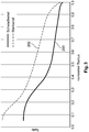
- Fig. 2 shows a diagram in which in each case the relative profile thickness is plotted over the normalized rotor radius for two different rotor blades of a wind turbine.
- the relative profile thickness namely the ratio of profile thickness to profile depth, can be specified in%, whereby it depends on the qualitative course and therefore no values are removed. Only the values for 38% and 45% are shown for orientation.
- the rotor radius here refers in each case to a rotor with at least one rotor blade mounted on a rotor hub of the rotor. The length of the respective rotor blade extends from the rotor blade root to the rotor blade tip.
- the rotor blade begins with its rotor blade root approximately at a value of 0.05 of the normalized rotor radius and ends with its rotor blade tip at the value 1 of the normalized rotor radius.
- the value of the normalized rotor radius corresponds approximately to the percentage length of the relevant rotor blade.
- the value 1 of the normalized rotor radius is equal to 100% of the rotor blade length.
- the graph 100 illustrates the profile of the relative profile thickness of a wind turbine for a low wind location and the graph 102 illustrates a profile of a wind turbine for locations with higher average wind speeds. From the graphs, it can be seen that the profile of the relative profile thickness of the graph 102 is substantially monotonously decreasing.
- Graph 102 begins in the region of the rotor blade root, that is, between a normalized rotor radius of 0.0 and 0.1 with a relative profile thickness of less than 45%. The values of the relative profile thickness decrease steadily.
- the graph 100 of the low-wind turbine starts at a significantly higher relative profile thickness. And falls only at about 15% of the normalized rotor position below the drawn 45% mark of the relative profile thickness and leaves this area only at about 50% of the normalized radius. At a normalized radial position of about 45%, the difference in the relative profile thickness between the low wind turbine of Graph 100 and the heavy wind turbine of Graph 102 is greatest.
- Fig. 3 is a diagram showing the profile depth - in the diagram simply referred to as depth - qualitatively as a function of the rotor radius, whose values are normalized to the maximum radius of the respective underlying rotor.
- the graph 200 shows the course for a low wind turbine, which is also the representation of FIG. 2 underlying, whereas the graph 202 shows the course of a strong wind turbine, which is also the FIG. 2 underlying. It can be seen that the low-wind turbine has a comparatively small depth at a very early stage, as compared to half the total radius, compared to the strong wind turbine.
- Fig. 4 shows a diagram in which the profile depths of FIG. 3 in each case the profile thickness - simplified in the diagram called thickness - is shown.
- the graphs 300 for the low-wind turbine and 402 for the high-wind turbine are shown only qualitatively above the normalized radius.
- the graphs 100, 200 and 300 on the one hand and the graphs 102, 202 and 402 are based on the same wind energy plant.
- the thickness profiles 300 and 302 are very similar for both types of plant in order to ensure the respective structural stability.
- a smaller depth is given in the outer rotor area to take into account the special conditions, such as Graph 200 of the FIG. 3 compared to graph 202. This results in the characteristic curve of the relative thickness according to graph 100 with the plateau in the range of about 40%, such as FIG. 2 shows.
- Fig. 5 shows a wind turbine 400 with a tower 402, which is built on a foundation 403.
- a nacelle 404 (nacelle) with a rotor 405 consisting essentially of a rotor hub 406 and rotor blades 407, 408 and 409 mounted thereon.
- the rotor 405 is connected to an electric generator inside the nacelle 404 for conversion coupled by mechanical work into electrical energy.
- the nacelle 404 is rotatably mounted on the tower 402, whose foundation 403 gives the necessary stability.
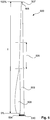
- Fig. 6 shows a side view of a rotor blade 500 of an embodiment over its entire length I, ie from 0% to 100%.
- the rotor blade 500 has a rotor blade root 504 at one end and a rotor blade tip 507 at the end remote from it.
- the rotor blade tip 507 is connected at a connection region 505 with the remaining part of the rotor blade.
- the rotor blade At the rotor blade root 504, the rotor blade has a large tread depth. In the connection area 505 and at the rotor blade tip 507, however, the tread depth is much smaller.
- the tread depth decreases, starting from the rotor blade root 504, which can also be referred to as profile root 504, to a central region 506. In the central region 506, a separation point may be provided (not shown here). From the central region 506 to the connection region 505, the tread depth is almost constant.
- the rotor blade 500 has a two-part shape in the region of the rotor blade root 504.
- the rotor blade 500 thus consists of a base profile 509, to which a further section 508 for increasing the rotor blade depth of the rotor blade 500 is arranged in the region of the rotor blade root 504.
- the section 508 is glued to the base profile 509, for example.
- Such a two-part mold is easier to handle when transporting to the site and easier to manufacture.
- FIG. 6 a hub connection area 510 can be seen. Via the hub connection region 510, the rotor blade 500 is connected to the rotor hub.
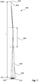
- FIG. 7 shows a further side view of the rotor blade 500 of FIG. 6 ,
- the rotor blade 500 with the base profile 509, the rotor blade depth increase section 508, the central region 506, the rotor blade root 504 and the hub connection region 510 and the connection region 505 to the rotor blade tip 507 can be seen.
- the rotor blade tip 507 is designed as a so-called winglet. As a result, vortices are reduced at the rotor blade tip.
- Fig. 1 to 7 illustrate a rotor blade or a wind turbine first without representation of the boundary layer fences and also without representation of vortex generators.
- Fig. 8 illustrates a problem that can occur with an underlying leaf of a light wind turbine.
- the illustration shows two different gradients of the local power coefficient, qualitatively plotted over the relative radius of the Rotor blade, namely the current radius r based on the maximum radius R of the underlying rotor.
- the value 1, ie 100% corresponds to the position of the blade tip and the value 0, ie 0%, to the axis of rotation of the underlying rotor. Since the sheet does not reach zero, the presentation starts at about 0.15.
- the two curves are simulation results of a three-dimensional numerical flow simulation. They show the local coefficient of performance quantitatively for two equal but differently contaminated rotor blades.
- the upper curve 700 shows the result for an essentially optimal rotor blade, which in particular has no soiling. This is always labeled “laminar-turbulent”.
- the lower curve 701 shows the result for basically the same rotor blade, but without optimal conditions, namely with soiling, which may also affect rain or raindrops on the sheet. This is in the Fig. 8 referred to as "fully turbulent".
- Fig. 9 shows a first boundary layer fence 810 and a second boundary layer fence 820. Both have a suction side section 811 and 821 and a pressure side section 812 and 822, respectively.
- Each of these sections 811, 812, 821 and 822 is designed as a web and has a base section B and a back section R, which for simplicity are designated here by the same letters in order to emphasize the functional similarity.
- Each base section B thus simultaneously identifies the profile of the blade in the respective profile section shown, namely for the suction side 801 and the pressure side 802.
- All fence sections 811, 812, 821 and 822 increase in height from an area in the vicinity of the rotor blade nose 803 Trailing edge 804 continuously closed.
- the reference numerals 801 to 804 are the same for both boundary layer fences 810 and 820 because they relate to the same rotor blade, only in the two views of Fig. 9 be shown at different radial positions.
- the Fig. 9 also shows for both boundary layer fences 810 and 820 a rotation axis 806 about which the pressure side or suction side contour is rotated in order to obtain the contour of the relevant back section R.
- This is illustrated only for the first boundary layer fence 810 and is illustrated there only for the suction side section 811, but is analogous to the pressure section 812 and also the boundary layer fence 820, viz each of the suction side portion 821 and the pressure side portion 822 mutatis mutandis transferable.
- the contour for the back section R is thus rotated by the angle of rotation ⁇ and this makes itself corresponding to the strongest at the end 808 noticeable.
- the angle of rotation ⁇ may be different for the different boundary layer sections 811, 812, 821 and 822.
- This design thus results for the fence sections a height h relative to the respective leaf surface.
- the height h changes along the respective web, ie increases from the leaf nose 803 to the trailing edge 804.
- This height h thus varies along the respective web and can also be different for the different fence sections 811, 812, 821 and 822.
- the variable h has been chosen for each fence section 811, 812, 821 and 822.
- Fig. 10 3 shows a rotor blade 800 in two views, namely a plan view of the suction side 801 and a plan view of the pressure side 802.
- the rotor blade 800 is shown from the root region 807 to the blade tip 808 and the respective plan view relates to the region of the blade tip 808 Root area 807 is twisted with respect to the blade tip area 808, which may be up to 45 to 50 °, so that the root area 807 does not appear to have the widest area, ie not the largest tread depth, but this is only a phenomenon of the perspective on this twisted area ,
- FIG. 12 shows the position of the first boundary layer fence 810 and the second boundary layer fence 820 and thus the position of the two suction side fence sections 811 and 821 and the pressure side fence sections 812 and 822.
- a rotor blade 800 of a rotor with a radius of 46 m is used.
- the first boundary layer fence 810 is arranged at a position of 15 m with respect to the radius of the rotor and the second boundary layer fence 820 is arranged at a position of 25 m.
- Fig. 10 also schematically shows a suction-side and a pressure-side position line 851 on the suction side 801 and 852 on the pressure side 802, each indicating a line along the vortex generators 853 and 854 are to be arranged.
- the vortex generators 853 and 854, which are also referred to as vortex generators, are also only indicated and can be provided in particular in a significantly higher number than shown.
- this embodiment shows vortex generators 853 on the suction side 801 only in the area between the first and second boundary layer fence 810 and 820.
- vortex generators 854 are also provided, which may be there also outside the area between the two boundary layer fences 810 and 820 to the blade root 807 out.
- FIG. 11 shows basically a section of the rotor blade 800, which essentially shows the suction side 801 of the rotor blade 800.
- the suction-side boundary layer fence sections 811 and 821 are clearly visible.
- the boundary layer fences or fence sections 821 and 811 fall out small and become larger towards the trailing edge 804, namely have a greater height than the rotor blade nose 803.
- the boundary layer fences are preferably mounted in a sheet section plane which is at a 90 ° angle to the rotor blade longitudinal axis.
- a production-related deviation thereof should not exceed a tolerance angle of 2 to 5 °, so that the end edge of the boundary layer fences, ie the area pointing to the sheet trailing edge, is not twisted more than this tolerance angle in the direction of the hub.
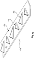
- Fig. 12 shows some vortex generators 870 in a perspective view.
- a direction of flow is indicated schematically by an arrow 872.
- the vortex generators are formed approximately triangular with a flat body, which is aligned perpendicular to the blade surface 874 and thereby obliquely to the flow direction 872 and thus is inclined to the direction of movement of the rotor blade. In this case, the inclination alternates from one vortex generator 870 to the next.
- the vortex generators have an alternating inclination to the direction of flow of the wind.
- the vortex generators also correspond in their nature and orientation about a shark fin, namely a shark fin, except that the shark fin is not oblique to the direction of flow.
- the vortex generators 870 may be applied to the rotor blade surface as a vortex generator bar 876.
- Rotor blade (1) according to embodiment 1, characterized in that the relative profile thickness (2) of the local maximum is 35% to 50%, in particular 40% to 45%.
- Rotor blade (1) according to one of embodiments 1 or 2, characterized in that the rotor blade (1) in the region of the local maximum has a tread depth of 1500 mm to 3500 mm, in particular about 2000 mm.
- Rotor blade (1) according to one of the preceding embodiments, characterized in that the rotor blade (1) is designed for a high-speed number in a range of 8 to 11, preferably from 9 to 10
- Rotor blade (1) characterized in that the rotor blade (1) in a range of 90% to 95%, the total length of the rotor blade, measured from the rotor blade root to the rotor blade tip has a tread depth (3), which is about 5% to 15%, in particular about 10%, corresponds to the tread depth (3) in the region of the rotor blade root (4) and / or that the rotor blade from 5% to 25% of the total length of the rotor blade, preferably from 5% to 35%, in particular from the rotor blade root to the central region, a linear thickness profile.
- Rotor blade (1) according to one of the preceding embodiments, characterized in that the rotor blade (1) at the rotor blade root (4) has a tread depth (3) of at least 3900 mm, in particular in a range of 3000 mm to 8000 mm, and / or in the range of 90% to 95% of the total length , in particular at 90%, starting from the rotor blade root (4), a profile depth (3) of a maximum of 1000 mm, in particular in a range of 700 mm to 300 mm.
- Rotor blade (1) according to one of the preceding embodiments, characterized in that the rotor blade (1) in the middle region has a tread depth which corresponds to about 20% to 30%, in particular about 25%, of the tread depth in the region of the rotor blade root (4)
Landscapes
- Engineering & Computer Science (AREA)
- Life Sciences & Earth Sciences (AREA)
- Sustainable Development (AREA)
- Sustainable Energy (AREA)
- Chemical & Material Sciences (AREA)
- Combustion & Propulsion (AREA)
- Mechanical Engineering (AREA)
- General Engineering & Computer Science (AREA)
- Physics & Mathematics (AREA)
- Fluid Mechanics (AREA)
- Wind Motors (AREA)
Description
- Die vorliegende Erfindung betrifft ein Rotorblatt einer Windenergieanlage. Außerdem betrifft die vorliegende Erfindung eine Windenergieanlage.
- Windenergieanlagen sind allgemein bekannt und heutzutage haben sich sogenannte Horizontalachsen-Windenergieanlagen durchgesetzt, auf die sich auch die vorliegende Anmeldung bezieht. Moderne Windenergieanlagen sind an die an ihrem Aufstellungsort zu erwartenden Windverhältnisse angepasst. Insbesondere kann grundsätzlich zwischen Windenergieanlagen für Starkwindstandorte und Windenergieanlagen für Schwachwindstandorte unterschieden werden. Ggf können weitere Untergliederungen vorgenommen werden.
- Windenergieanlagen für Schwachwindstandorte weisen im Vergleich zu Windenergieanlagen für Standorte mit höheren mittleren Windgeschwindigkeiten längere und zumindest abschnittsweise auch filigranere Rotorblätter auf. Hierdurch können diese längeren Rotorblätter eine größere Rotorfläche überstreichen, um somit auch bei schwachem Wind diesem möglichst viel Energie entnehmen zu können. Starke Belastungen durch starken Wind treten vergleichsweise selten auf.
- Für den Bau solcher Rotorblätter ist darauf zu achten, dass dies besonders im mittleren Bereich so schmal sind, dass sie möglichst wenig Gewicht aufweisen, gleichzeitig aber eine ausreichende Tragfähigkeit für das Blatt gewährleisten können. Insbesondere im mittleren Bereich des Rotorblattes, bezogen auf die radiale Richtung des Rotors, kann es Probleme bereiten, die beschriebenen Anforderungen an die Stabilität und Tragfähigkeit des Rotorblattes mit dem erforderlichen aerodynamischen Design in Einklang zu bringen.
- Der Spielraum zur Auslegung des aerodynamischen Profils kann dabei mitunter so klein sein, dass zwar ein aerodynamisches Profil mit guten Eigenschaften erzielt wird, dass aber leichte Abweichungen dieses optimalen aerodynamischen Profils für die Strömungseigenschaften signifikant sein können. Insbesondere Verunreinigungen des Rotorblattes können zu einem unerwünscht frühen Strömungsabriss führen, der bei einem verunreinigungsfreien Blatt nicht oder zumindest nicht in dem Maße auftritt. Dabei können mitunter Regentropfen als signifikante Verunreinigung des Blattes ausreichen.
- Der vorliegenden Erfindung liegt somit die Aufgabe zugrunde, zumindest eines der oben genannten Probleme zu adressieren. Insbesondere soll eine Lösung zur Verbesserung aerodynamischer Eigenschaften eines Rotorblattes angegeben werden. Insbesondere soll ein Rotorblatt einer Windenergieanlage für Schwachwindstandorte verbessert, insbesondere verschmutzungsunanfälliger gemacht werden. Zumindest soll eine zum Stand der Technik alternative Lösung vorgeschlagen werden.
- Das Deutsche Patent- und Markenamt hat in der Prioritätsanmeldung zu vorliegender PCT-Anmeldung folgenden Stand der Technik recherchiert:
DE 103 47 802 B3 US 2011/0211966 A1 ,US 2012/0051936 A1 undEP 2 466 122 A2 . - Erfindungsgemäß wird ein Rotorblatt gemäß Anspruch 1 vorgeschlagen. Ein solches Rotorblatt, nämlich das eines aerodynamischen Rotors, umfasst wenigstens einen ersten und einen zweiten Grenzschichtzaun. Die Position dieser Grenzschichtzäune ist speziell auf einen mittleren Bereich, bezogen auf eine radiale Richtung des aerodynamischen Rotors, abgestimmt. Die Position der wenigstens zwei Grenzschichtzäune ist so gewählt, dass diese Grenzschichtzäune einen mittleren Bereich des Rotorblattes einschließen.
- Hierbei liegt die Überlegung zugrunde, dass das Rotorblatt im nabennahen Bereich auch bei Schwachwindanlagen, also bei Windenergieanlage für Schwachwindstandorte, breit ausgeführt sein kann und ein weniger anfälliges Profil zulässt. Im äußeren Bereich, also zur Rotorblattspitze hin, kann ebenfalls eine robustere Profilauslegung vorgenommen werden, weil in diesem äußeren Bereich die Tragfähigkeit des Rotorblattes das Blattdesign weniger dominant bestimmt. Im mittleren Bereich spielt dabei die Tragfähigkeit des Rotorblattes in diesem Bereich eine große Rolle und der Einfluss des Windes auf den Ertrag der Windenergieanlage ist auch hier noch recht groß. Außerdem können in dem mittleren Bereich mitunter größere Einflüsse durch Verschmutzungen wie Regen auftreten, weil die Umlaufgeschwindigkeit hier nicht so hoch ist wie im äußeren Bereich des Blattes und somit sich Regenwasser besser an der Oberfläche halten kann.
- An dieser Stelle wird darauf hingewiesen, dass die Verwendung von Grenzschichtzäunen bei Rotorblättern von Windenergieanlagen grundsätzlich bekannt ist. In diesem Zusammenhang wird auf das deutsche Patent
DE 103 47 802 B3 verwiesen. Dort sind Grenzschichtzäune vorgesehen, um Querströmungen zwischen einem im Wesentlichen zylindrischen Wurzelbereich des Rotorblattes zu dem ein aerodynamisches Profil aufweisenden äußeren Teil des Rotorblattes zu verhindern. Dazu wird dort ein Grenzschichtzaun an dem Bereich vorgeschlagen, an dem das Rotorblatt von seinem etwa zylindrischen Wurzelbereich zu dem Bereich übergeht, der ein aerodynamisches Profil aufweist. Ein zweiter Grenzschichtzaun kann zur Unterstützung vorgesehen sein. - Die vorliegende Erfindung betrifft dagegen ein gänzliches anderes Problem, nämlich einen Strömungsabriss insbesondere bedingt durch Blattverunreinigungen zu verhindern oder zumindest auf einen vorbestimmten Bereich einzugrenzen. Dabei betrifft die vorliegende Erfindung insbesondere Rotorblätter, die ihre größte Profiltiefe unmittelbar in ihrem Wurzelbereich zum Befestigen an einer Rotornabe hat. Mit anderen Worten betrifft die vorliegende Erfindung insbesondere Rotorblätter, die auf ihrer vollständigen Axial- bzw. Radiallänge ein aerodynamisches Profil aufweisen.
- Dafür wird vorgeschlagen, dass der erste Grenzschichtzaun in einem Bereich von 25 bis 40% angeordnet ist und dass der zweite Grenzschichtzaun an dem Rotorblatt in einem Bereich von 45 bis 60% angeordnet ist. Diese Angaben beziehen sich auf die radiale Richtung des Rotorblattes bei bestimmungsgemäßer Verwendung in dem aerodynamischen Rotor der Windenergieanlage. Demnach wäre ein Wert von 0% genau bei der Drehachse des aerodynamischen Rotors und ein Wert von 100% an der Rotorblattspitze des Rotorblattes.
- Vorzugsweise ist der erste Grenzschichtzaun in einem Bereich von 30 bis 35% in radialer Richtung angeordnet und außerdem oder alternativ ist der zweite Grenzschichtzaun an dem Rotorblatt in radialer Richtung in einem Bereich von 50 bis 55% angeordnet. Hierdurch wird ein entsprechend konkreter mittlerer Bereich des Rotorblattes mit diesen beiden Grenzschichtzäunen versehen und zwischen diesen beiden eingeschlossen. Die vorgeschlagene Maßnahme kann sich somit konkret auf diesen mittleren Bereich konzentrieren.
- Vorzugsweise ist der erste und der zweite Grenzschichtzaun jeweils an der Saugseite des Rotorblattes angeordnet. Insbesondere wurde erkannt, dass hier die meisten Probleme mit einem Strömungsabriss auftreten können, so dass insbesondere hier die Grenzschichtzäune vorgesehen werden. Vorzugsweise ist nicht nur jeweils ein Grenzschichtzaun an der Saugseite des Rotorblattes angeordnet, sondern jeder Grenzschichtzaun weist zwei Zaunabschnitte auf, von denen ein Zaunabschnitt an der Saugseite und der andere Zaunabschnitt an der Druckseite des Rotorblattes angeordnet ist. Hierbei wurde erkannt, dass eine Unterstützung des Grenzschichtzauns der Saugseite durch einen Zaunabschnitt an der Druckseite die vorgeschlagene aerodynamische Maßnahme noch verbessern kann. Etwaige Strömungsabrissphänomene können damit noch wirksamer auf diesen mittleren Bereich des Rotorblattes beschränkt werden.
- Gemäß einer Ausführungsform ist jeder Grenzschichtzaun so ausgebildet, dass er von der Blattnase zur Hinterkante verlaufend in seiner Höhe zunimmt. Insoweit wird von einem üblichen Rotorblatt ausgegangen, das etwa in Bewegungsrichtung eine Blattnase oder Rotorblattnase aufweist und zu dieser abgewandt, also im Grunde nach hinten, eine Hinterkante aufweist. Vorzugsweise orientiert sich die Höhe des Grenzschichtzauns an der Dicke der Grenzschicht der das Blatt anströmenden Luft. Diese Grenzschicht wird als der Bereich angenommen, bei dem die anströmende Luftgeschwindigkeit einen so großen Abstand zur Blattoberfläche hat, dass sie 90% der ungebremsten Strömungsgeschwindigkeit der Luft erreicht hat. Hierbei wird die Strömungsgeschwindigkeit der Luft relativ zu dem Rotorblatt an der betreffenden Stelle zugrunde gelegt.
- Es hat sich nun herausgestellt, dass diese Grenzschicht von der Blattnase zur Hinterkante einen zunehmenden Abstand aufweist. Gemäß einer Ausführungsform wird vorgeschlagen, dass sich die Höhe des Grenzschichtzauns daran orientiert.
- Diese Ausführungen zur Höhe des Grenzschichtzauns setzen einen Grenzschichtzaun voraus, der etwa als flaches, senkrecht zur Blattoberfläche und längs zur Anströmrichtung ausgebildetes Objekt ausgestaltet ist, also etwa stegförmig ausgebildet ist. Außerdem sind die Ausführungen auch anzuwenden für Grenzschichtzaunabschnitte, die vereinfachend auch als Zaunabschnitte bezeichnet wurden, wenn der Grenzschichtzaun jeweils einen Zaunabschnitt auf der Saugseite und einen auf der Druckseite aufweist.
- Insbesondere beginnt der Grenzschichtzaun in der Nähe der Blattnase, z.B. bezogen auf eine Sehne des Blattprofils an der betreffenden Stelle bei 5 bis 10% hinter der Blattnase. Hier beginnt der Grenzschichtzaun bzw. der Zaunabschnitt mit einer geringen Höhe von 0 bis 5 mm und erhöht sich dann kontinuierlich bis zu einer Höhe von über 15 mm, insbesondere über 20 mm. Diese Erhöhung kann bei dem ersten Grenzschichtzaun bzw. dessen Zaunabschnitten auf über 30 mm ansteigen. Vorzugsweise ist der Grenzschichtzaun in seinem hinteren Bereich, insbesondere hinteren Drittel, in seiner Höhe gleichbleibend, nämlich gleichbleibend hoch. Hierdurch kann sich dieser an die Position der Grenzschicht anpassen und es werden unnötig große Höhen und damit unnötige Angriffsflächen vermieden und schließlich auch Materialeinsparungen gegenüber einer Variante mit gleichbleibend großer Höhe erreicht.
- Vorzugsweise ist somit jeder Grenzschichtzaun bzw. Zaunabschnitt als Steg ausgebildet und dieser Steg weist einen Basisabschnitt und einen Rückenabschnitt ab. Mit dem Basisabschnitt ist der Steg auf der Rotorblattoberfläche, also auf der Saugseite oder Druckseite befestigt und die andere, freie Seite des Stegs bildet der Rückenabschnitt. Der Basisabschnitt folgt somit dem Blattprofil. Der Rückenabschnitt ist ebenfalls wie das Blattprofil ausgebildet, aber an einer anderen Position. Hierzu wird eine Konturlinie zugrunde gelegt, die in ihrer Form dem Blattprofil entspricht, die aber um eine Dreh-/Rotationsachse gegenüber dem Blattprofil verdreht/rotiert ist. Diese Betrachtungsweisen gehen von einem Profilschnitt im Bereich des jeweils betrachteten Grenzschichtzauns aus. Es wird somit zunächst eine Konturlinie angenommen, die dem Blattprofil, z.B. an der Saugseite, folgt. Dann wird, gedanklich, eine Drehachse angesetzt, vorzugsweise im Bereich der Blattnase. Um diese Drehachse wird dann diese Konturlinie - gedanklich - rotiert, insbesondere um einen Winkel von etwa 1 bis 3°, so dass diese Konturlinie dann mit dem Blattprofil einen gemeinsamen Punkt in der Drehachse hat, sich ansonsten aber nach hinten zur Hinterkante hin kontinuierlich von dem Blattprofil, also in diesem Beispiel von der Saugseite, entfernt. Der Grenzschichtzaun bzw. Grenzschichtzaunabschnitt verläuft somit zwischen dem Blattprofil und dieser gedrehten Konturlinie.
- Entsprechend wird, wenn ein Zaunabschnitt an der Druckseite vorgesehen ist, die Konturlinie der Druckseite zugrunde gelegt und sie bildet den Verlauf der Basis des Stegs und die dazu gedrehte Konturlinie bildet den Verlauf des Rückens des Stegs. Der Drehsinn um dieselbe Achse, ist dabei genau umgekehrt, wie bei der Ausbildung des saugseitigen Grenzschichtzaunes.
- Im vorderen Bereich zur Blattnase, also insbesondere im Bereich von 5 bis 10% bezogen auf die Sehne des Blattes, wäre die Höhe des Steges hierbei so gering, dass der Steg dort nicht ausgebildet zu werden braucht und es ausreichend ist, wenn der Steg in einem entsprechenden Abstand zur Blattnase erst beginnt. Dies gilt sowohl für die Saugseite als auch für die Druckseite.
- Vorzugsweise orientiert sich die Höhe des Grenzschichtzauns an der zwei- bis fünffachen, insbesondere drei- bis vierfachen Größe der Verdrängungsdicke der Grenzschicht in dem entsprechenden Bereich.
- Zudem wurde auch erkannt, dass eine geringe Höhe des Grenzschichtzauns zur Blattnase hin ausreichend sein kann, weil Strömungsabrisse, die durch die vorgeschlagenen Maßnahmen verhindert werden sollen, erst im mittleren oder sogar hinteren Bereich des Blattes bzw. des Blattprofils auftreten. Entsprechend ist eine höhere Höhe des Grenzschichtzauns mit zunehmender Position zur Hinterkante hin vorteilhaft.
- Eine weitere Ausführungsform schlägt vor, dass der erste und zweite Grenzschichtzaun unterschiedliche Höhen aufweisen, insbesondere unterschiedliche mittlere Höhen aufweisen. Soweit die Grenzschichtzäune als Steg ausgebildet sind mit einem Stegrücken, der der gedrehten Profillinie folgt, ergibt sich auf der gesamten Länge des Stegs eine höhere Höhe des ersten Grenzschichtzauns gegenüber dem zweiten Grenzschichtzaun. Als Vergleich wird vereinfachend eine mittlere Höhe der beiden Grenzschichtzäune zugrunde gelegt, die beispielsweise ein arithmetisches Mittel der Höhe des Verlaufs des jeweiligen Grenzschichtzauns sein kann. Weist der Grenzschichtzaun auch einen Zaunabschnitt an der Druckseite auf, sind diese Überlegungen und Schilderungen sinngemäß auf die Höhe des jeweiligen Zaunabschnitts anzuwenden.
- Jedenfalls wird vorgeschlagen, dass der erste Grenzschichtzaun, also derjenige, der näher zur Rotornabe hin angeordnet ist, wenigstens 30%, insbesondere wenigstens 50% höher ist als der zweite Grenzschichtzaun. Hierbei wurde erkannt, dass für den äußeren Grenzschichtzaun eine geringe Höhe ausreichend ist, was aerodynamisch vorteilhaft sein kann.
- Vorzugsweise sind ergänzend Wirbelgeneratoren vorgesehen. Solche Wirbelgeneratoren, die etwa im vorderen Drittel zur Blattnase hin angeordnet sind und sich vorzugsweise auf der Saugseite des Rotorblattes befinden, können einem Ablöseeffekt, also einem Strömungsabriss am Blattprofil entgegenwirken. Insbesondere können sie bewirken, dass sich eine Position eines solchen Strömungsabrisses weiter zur Hinterkante verlegt und damit die aerodynamischen Nachteile durch den Strömungsabriss zumindest vermindert werden. Gelingt es, diesen Strömungsabriss - gedanklich - bis zur Hinterkante zu verschieben, tritt er faktisch nicht mehr auf.
- Vorzugsweise wird vorgeschlagen, dass diese Wirbelgeneratoren nur zwischen dem ersten und zweiten Grenzschichtzaun angeordnet werden. Ihre Wirkung ist somit auf diesen Bereich beschränkt und diese wird auch durch die Grenzschichtzäune zum äußeren bzw. inneren Bereich des Rotorblattes abgeschirmt. Insbesondere wird hierbei auch dem Problem Rechnung getragen, dass solche Wirbelgeneratoren eine unerwünschte Geräuschquelle sein können. Durch die Anordnung ausschließlich in diesem Bereich zwischen den beiden Grenzschichtzäunen kann somit auch ein Geräuschpegel begrenzt werden, indem eine in radialer Richtung unnötig weite Belegung mit Wirbelgeneratoren vermieden wird/werden kann.
- Vorzugsweise ist das Rotorblatt für eine Schwachwindanlage ausgelegt, also für eine Windenergieanlage, die für einen Schwachwindstandort vorgesehen ist. Somit adressieren die vorgeschlagenen Lösungen insbesondere einen problematischen Mittelbereich eines solchen Rotorblatts einer Schwachwindanlage.
- Vorzugsweise wird ein Rotorblatt zugrunde gelegt, das seine größte Profiltiefe unmittelbar an seiner Blattwurzel zum Befestigen an der Rotornabe aufweist. Es wird also kein Rotorblatt verwendet, das sich zur Nabe hin wieder verschlankt und einen im Wesentlichen zylindrischen Bereich aufweist, der nicht als Blattprofil ausgelegt ist. Mit anderen Worten betreffen die vorliegenden Lösungen somit keine Effekte, die zwischen einem Profilbereich des Rotorblattes und einem unprofilierten Bereich des Rotorblattes, nämlich einer zylindrischen Blattwurzel, auftreten.
- Erfindungsgemäß wird zudem eine Windenergieanlage vorgeschlagen, die mit einem oder mehreren Rotorblättern gemäß wenigstens einer der oben beschriebenen Ausführungsformen ausgestattet ist. Insbesondere wird eine Windenergieanlage mit drei Rotorblättern vorgeschlagen, von denen jedes Rotorblatt wie gemäß einem der obigen Ausführungsformen vorgeschlagen ausgebildet ist.
- Ein bevorzugtes Rotorblatt einer Windenergieanlage weist eine Rotorblattwurzel zur Anbindung des Rotorblattes an einer Rotornabe und eine zur Rotorblattwurzel abgewandten Seite angeordneten Rotorblattspitze auf. Dabei weist eine relative Profildicke, die als Verhältnis von Profildicke zu Profiltiefe definiert ist, in einem mittleren Bereich zwischen Rotorblattwurzel und Rotorblattspitze ein lokales Maximum auf. Unter der Profiltiefe wird im Folgenden die Länge des Profils, also der Abstand zwischen Profilnase und Profilhinterkante verstanden. Die Profildicke bezeichnet den Abstand zwischen Profilober- und Profilunterseite. Die relative Profildicke weist somit einen geringen Wert auf, wenn die Profildicke klein ist und/oder die Profiltiefe groß ist.
- Die relative Profildicke weist zwischen Rotorblattwurzel und Rotorblattspitze ein lokales Maximum auf. Das lokale Maximum befindet sich im mittleren Bereich zwischen Rotorblattwurzel und Rotorblattspitze, vorzugsweise in einem Bereich von 30 bis 60% der Gesamtlänge des Rotorblattes, gemessen von der Rotorblattwurzel zur Rotorblattspitze. Bei einer Gesamtlänge von bspw. 60 Metern befindet sich das lokale Maximum somit in einem Bereich von vorzugsweise 18 Metern bis 36 Metern. Die relative Profildicke nimmt also zunächst ausgehend von der Rotorblattwurzel ab und steigt dann in dem mittleren Bereich wieder bis zu dem lokalen Maximum an, nämlich bis zu einer Stelle an, in deren Umgebung die relative Profildicke keinen höheren Wert aufweist. Das lokale Maximum im mittleren Bereich des Rotorblatts kommt insbesondere dadurch zustande, dass die Profiltiefe ausgehend von der Rotorblattwurzel bis zum mittleren Bereich stark abnimmt. Gleichzeitig oder alternativ kann die Profildicke erhöht werden bzw. nicht so stark wie die Profiltiefe abnehmen. Dadurch wird eine Materialeinsparung erzielt, insbesondere zwischen Rotorblattwurzel und dem mittleren Bereich, und somit eine Gewichtseinsparung. Durch die Erhöhung der Profildicke wird eine hohe Stabilität des Rotorblattes erzeugt.
- Es wurde erkannt, dass eine Abnahme der Profiltiefe im mittleren Bereich zwar dort eine Verringerung der Tragfähigkeit zur Folge haben kann, dass aber gleichzeitig eine Verringerung des Gewichts des Rotorblattes erreicht wird. Eine etwaige Verschlechterung der Effizienz des Rotorblattes wird zum Erreichen eines geringeren Gewichts in Kauf genommen. Dabei wird im mittleren Bereich bei möglichst guter Effizienz aber stärker auf Stabilität und Steifigkeit fokussiert und im äußeren Bereich stärker auf eine hohe Effizienz fokussiert. Somit wird ein Profil vorgeschlagen, bei dem, die Profiltiefe vom mittleren Bereich nach außen zur Rotorblattspitze hin zumindest schwächer abnimmt als im mittleren Bereich.
- Vorzugsweise beträgt die relative Profildicke des lokalen Maximums 35% bis 50%, insbesondere 40% bis 45%. Üblicherweise beginnt die relative Profildicke an der Rotorblattwurzel bei einem Wert von 100% bis 40%. Ein Wert von etwa 100% bedeutet dabei, dass die Profildicke in etwa mit der Profiltiefe identisch ist. Danach fällt der Wert monoton ab. In einer erfindungsgemäßen Ausführungsform fällt der Wert ausgehend von der Rotorblattwurzel zunächst ab, bis er ein lokales Minimum erreicht. Nach dem lokalen Minimum verzeichnet die relative Profildicke einen Anstieg bis sie etwa 35% bis 50% beträgt.
- In einer bevorzugten Ausführungsform weist das Rotorblatt im mittleren Bereich und/oder im Bereich des lokalen Maximums eine Profiltiefe von 1500mm bis 3500mm, insbesondere etwa 2000mm auf. Wenn das Rotorblatt im Bereich der Rotorblattwurzel eine Profiltiefe von etwa 6000mm aufweist, sinkt die Profiltiefe also bis zum mittleren Bereich und/oder bis zum Bereich des lokalen Maximums um etwa ein Drittel.
- Vorzugsweise ist das Rotorblatt für eine Schnelllaufzahl in einem Bereich von 8 bis 11, vorzugsweise von 9 bis 10, ausgelegt. Dabei ist die Schnelllaufzahl als das Verhältnis von Umfangsgeschwindigkeit an der Rotorblattspitze zur Windgeschwindigkeit definiert. Hohe Auslegungsschnelllaufzahlen zusammen mit einem hohen Leistungsbeiwert können durch schlanke, schnell rotierende Blätter erreicht werden.
- In einer weiteren Ausführungsform weist das Rotorblatt in einem Bereich von 90% bis 95% der Gesamtlänge des Rotorblattes, gemessen von der Rotorblattwurzel zur Rotorblattspitze, eine Profiltiefe auf, welche etwa 5% bis 15%, insbesondere etwa 10% der Profiltiefe im Bereich der Rotorblattwurzel entspricht.
- Durch eine solche reduzierte Profiltiefe im Bereich der Rotorblattspitze werden auf den Maschinenbau und den Turm wirkende Lasten, insbesondere aerodynamische Lasten, reduziert. Es wird im Grunde ein verhältnismäßig schlankes Rotorblatt vorgeschlagen.
- In einer bevorzugten Ausführungsform weist das Rotorblatt bei der Rotorblattwurzel eine Profiltiefe von wenigstens 3900 mm, insbesondere in einem Bereich von 3000 mm bis 8000 mm auf und/oder im Bereich von 90% bis 95% der Gesamtlänge, insbesondere bei 90%, ausgehend von der Rotorblattwurzel, eine Profiltiefe von maximal 1000 mm, insbesondere in einem Bereich von 700 mm bis 300 mm auf.
- Vorzugsweise weist das Rotorblatt im mittleren Bereich, insbesondere bei 50% der Gesamtlänge des Rotorblattes und/oder im Bereich des lokalen Maximums eine Profiltiefe auf, welche etwa 20% bis 30%, insbesondere etwa 25%, der Profiltiefe im Bereich der Rotorblattwurzel entspricht. Beträgt beispielsweise die Profiltiefe im Bereich der Rotorblattwurzel 6000 mm, entspricht die Profiltiefe im Bereich des lokalen Maximums und/oder im mittleren Bereich nur noch etwa 1500 mm. Durch diese schnelle Abnahme der Profiltiefe von der Rotorblattwurzel bis zum mittleren Bereich entsteht ein schlankes Profil mit geringen Lasten, insbesondere aerodynamischen Lasten. Die Lasten sind geringer als bei anderen bekannten Rotorblättern. Bei den bekannten Profilen nimmt die Rotorblatttiefe üblicherweise im Wesentlichen linear ab. Dadurch ist insbesondere zwischen der Rotorblattwurzel und dem mittleren Bereich eine höhere Profiltiefe vorhanden und somit auch mehr Material.
- Vorzugsweise wird eine Windenergieanlage für einen Schwachwindstandort mit wenigstens einem Rotorblatt nach wenigstens einer der vorstehenden Ausführungen vorgeschlagen. Eine solche Windenergieanlage ist durch wenigstens ein schlankes und schnell rotierendes Rotorblatt durch eine hohe Auslegungsschnelllaufzahl und einen hohen Leistungsbeiwert wirtschaftlich effizient. Die Windenergieanlage ist dadurch insbesondere auch für den Betrieb im Teillastbereich und/oder für schwachen Wind und somit auch für Binnenstandorte geeignet. Die Windenergieanlage weist vorzugsweise drei Rotorblätter auf.
- Nachfolgend wird die Erfindung anhand von Ausführungsbeispielen unter Bezugnahme auf die begleitenden Figuren exemplarisch erläutert. Die Figuren enthalten dabei teilweise vereinfachte, schematische Darstellungen.
- Fig. 1
- zeigt eine schematische Darstellung eines Rotorblattes.
- Fig. 2
- zeigt ein Diagramm, in dem die relative Profildicke qualitativ über dem normierten Rotorradius dargestellt ist.
- Fig. 3
- zeigt ein Diagramm, in dem die Tiefe qualitativ über dem Radius dargestellt ist.
- Fig. 4
- zeigt ein Diagramm, in dem die Dicke qualitativ über dem Radius dargestellt ist.
- Fig. 5
- zeigt eine Windenergieanlage in einer perspektivischen Ansicht.
- Fig. 6
- zeigt ein Rotorblatt in einer Seitenansicht.
- Fig. 7
- zeigt das Rotorblatt der
Figur 6 in einer weiteren Seitenansicht. - Fig. 8
- zeigt einen lokalen Leistungsbeiwert cp_loc qualitativ für zwei Zustände abhängig der radialen Position an dem Rotorblatt.
- Fig. 9
- zeigt den ersten und zweiten Grenzschichtzaun in einer rotorblattaxialen Ansicht.
- Fig. 10
- zeigt ein Rotorblatt in zwei Ansichten.
- Fig. 11
- zeigt einen Teil eines Rotorblattes in einer perspektivischen Ansicht.
- Fig. 12
- zeigt einige Wirbelgeneratoren exemplarisch in einer perspektivischen Ansicht.
-
Fig. 1 zeigt eine Verteilung verschiedener Profilgeometrien eines Rotorblattes 1 einer Ausführungsform. In dem Rotorblatt 1 sind abschnittsweise Profildicken 2 und Profiltiefen 3 dargestellt. Das Rotorblatt 1 weist an einem Ende die Rotorblattwurzel 4 und an dem dazu abgewandten Ende einen Anschlussbereich 5 zum Anbringen einer Rotorblattspitze auf. An der Rotorblattwurzel 4 weist das Rotorblatt eine große Profiltiefe 3 auf. Im Anschlussbereich 5 ist die Profiltiefe 3 dagegen sehr viel kleiner. Die Profiltiefe nimmt, ausgehend von der Rotorblattwurzel 4, die auch als Profilwurzel 4 bezeichnet werden kann, bis zu einem mittleren Bereich 6 deutlich ab. In dem mittleren Bereich 6 kann eine Trennstelle vorgesehen sein (hier nicht dargestellt). Vom mittleren Bereich 6 bis zum Anschlussbereich 5 ist die Profiltiefe 3 nahezu konstant. Das gezeigte Rotorblatt 1 ist zum Anbringen einer kleinen Rotorblattspitze vorgesehen, die weniger als 1% der Länge des gezeigten Rotorblatts 1 ausmacht und daher hier vernachlässigt werden kann. -
Fig. 2 zeigt ein Diagramm, in dem für zwei verschiedene Rotorblätter einer Windenergieanlage jeweils die relative Profildicke über den normierten Rotorradius eingezeichnet ist. Die relative Profildicke, nämlich das Verhältnis von Profildicke zu Profiltiefe, kann in % angegeben werden, wobei es hier auf den qualitativen Verlauf ankommt und daher keine Werte abgetragen sind. Es sind nur die Werte für 38% und 45% zur Orientierung eingezeichnet. Der Rotorradius bezieht sich hierbei jeweils auf einen Rotor mit wenigstens einem an einer Rotornabe des Rotors montierten Rotorblatt. Die Länge des jeweiligen Rotorblattes erstreckt sich von der Rotorblattwurzel zur Rotorblattspitze. Das Rotorblatt beginnt mit seiner Rotorblattwurzel etwa bei einem Wert von 0,05 des normierten Rotorradius und endet mit seiner Rotorblattspitze bei dem Wert 1 des normierten Rotorradius. Im Bereich der Rotorblattspitze entspricht der Wert des normierten Rotorradius etwa der prozentualen Länge des betreffenden Rotorblattes. Insbesondere ist der Wert 1 des normierten Rotorradius gleich 100% der Rotorblattlänge. - In dem Diagramm sind zwei Graphen 100 und 102 zu erkennen. Der Graph 100 stellt den Verlauf der relativen Profildicke einer Windenergieanlage für einen Schwachwindstandort dar und der Graph 102 stellt einen Verlauf einer Windenergieanlage für Standorte mit höheren mittleren Windgeschwindigkeiten dar. Anhand der Graphen ist zu erkennen, dass der Verlauf der relativen Profildicke des Graphen 102 im Wesentlichen monoton fallend verläuft. Der Graph 102 beginnen im Bereich der Rotorblattwurzel, also zwischen einem normierten Rotorradius von 0,0 und 0,1 bei einer relativen Profildicke unter 45%. Die Werte der relativen Profildicke nehmen stetig ab.
- Der Graph 100 der Schwachwindanlage beginnt bei einer deutlich höheren relativen Profildicke. Und fällt erst bei etwa 15% der normierten Rotorposition unter die eingezeichnete 45%-Marke der relativen Profildicke und verlässt diesen Bereich erst bei etwa 50% des normierten Radius. Bei einer normierten radialen Position von etwa 45% ist der Unterschied der relativen Profildicke zwischen der Schwachwindanlage gemäß Graph 100 und der Starkwindanlage gemäß Graph 102 am größten.
- Die Darstellung zeigt somit, dass bei der Schwachwindanlage die Abnahme der relativen Dicke sehr weit nach außen verlagert ist, im Vergleich mit der Starkwindanlage. Besonders für Bereich von 40% bis 45%, an dem die relative Dicke im Vergleich zur Starkwindanlage am größten ist, wird vorgeschlagen, Grenzzäune zum vorzusehen, die diesen Bereich einfassen können und/oder es werden hier Wirbelgeneratoren vorgesehen.
- In
Fig. 3 ist ein Diagramm dargestellt, welches die Profiltiefe - in dem Diagramm vereinfacht als Tiefe bezeichnet - qualitativ in Abhängigkeit des Rotorradius zeigt, dessen Werte auf den maximalen Radius des jeweils zugrunde liegenden Rotors normiert. Der Graph 200 zeigt den Verlauf für eine Schwachwindanlage, die auch der Darstellung derFigur 2 zugrunde lag, wohingegen der Graph 202 den Verlauf einer Starkwindanlage zeigt, die auch derFigur 2 zugrunde lag. Darin ist zu erkennen, dass die Schwachwindanlage sehr früh, als schon etwa auf der Hälfte des gesamten Radius, eine vergleichsweise geringe Tiefe aufweist, verglichen mit der Starkwindanlage. -
Fig. 4 zeigt ein Diagramm, in dem zu den Profiltiefen derFigur 3 jeweils die Profildicke - in dem Diagramm vereinfacht als Dicke bezeichnet - dargestellt ist. Auch hier sind die Graphen 300 für die Schwachwindanlage und 402 für die Starkwindanlage nur qualitativ über den normierten Radius dargestellt. Den Graphen 100, 200 und 300 einerseits und den Graphen 102, 202 und 402 liegen jeweils dieselbe Windenergieanlage zugrunde. - Es ist zu erkennen, dass die Dickenverläufe 300 und 302 für beide Anlagentypen ganzähnlich sind, um die jeweilige Strukturstabilität zu gewährleisten. Für die Schwachwindanlage wird nun aber im äußeren Rotorbereich eine geringere Tiefe vorgegeben, um den besonderen Bedingungen Rechnung zu tragen, wie Graph 200 der
Figur 3 im Vergleich zum Graphen 202 zeigt. Daraus ergibt sich der charakteristische Verlauf der relativen Dicke gemäß Graph 100 mit dem Plateau im Bereich um etwa 40%, wieFigur 2 zeigt. -
Fig. 5 zeigt eine Windenergieanlage 400 mit einem Turm 402, der auf einem Fundament 403 errichtet ist. Am oberen, dem Fundament 403 gegenüberliegenden Ende befindet sich eine Gondel 404 (Maschinenhaus) mit einem Rotor 405, der im Wesentlichen aus einer Rotornabe 406 und daran angebrachten Rotorblättern 407, 408 und 409 besteht. Der Rotor 405 ist mit einem elektrischen Generator im Innern der Gondel 404 zur Wandlung von mechanischer Arbeit in elektrische Energie gekoppelt. Die Gondel 404 ist drehbar auf dem Turm 402 gelagert, dessen Fundament 403 die notwendige Standsicherheit gibt. -
Fig. 6 zeigt eine Seitenansicht eines Rotorblattes 500 einer Ausführungsform über seine Gesamtlänge I, d.h. von 0% bis 100%. Das Rotorblatt 500 weist an einem Ende eine Rotorblattwurzel 504 und an dem dazu abgewandten Ende eine Rotorblattspitze 507 auf. Die Rotorblattspitze 507 ist an einem Anschlussbereich 505 mit dem restlichen Teil des Rotorblattes verbunden. An der Rotorblattwurzel 504 weist das Rotorblatt eine große Profiltiefe auf. Im Anschlussbereich 505 und an der Rotorblattspitze 507 ist die Profiltiefe dagegen sehr viel kleiner. Die Profiltiefe nimmt, ausgehend von der Rotorblattwurzel 504, die auch als Profilwurzel 504 bezeichnet werden kann, bis zu einem mittleren Bereich 506 deutlich ab. In dem mittleren Bereich 506 kann eine Trennstelle vorgesehen sein (hier nicht dargestellt). Vom mittleren Bereich 506 bis zum Anschlussbereich 505 ist die Profiltiefe nahezu konstant. - Das Rotorblatt 500 weist im Bereich der Rotorblattwurzel 504 eine zweigeteilte Form auf. Das Rotorblatt 500 besteht somit aus einem Grundprofil 509, an das in dem Bereich der Rotorblattwurzel 504 ein weiterer Abschnitt 508 zur Erhöhung der Rotorblatttiefe des Rotorblattes 500 angeordnet ist. Der Abschnitt 508 ist dabei beispielsweise an das Grundprofil 509 angeklebt. Eine solche zweigeteilte Form ist einfacher in der Handhabung beim Transport zum Aufstellungsort und einfacher zu fertigen.
- Weiterhin ist in
Figur 6 ein Nabenanschlussbereich 510 zu erkennen. Über den Nabenanschlussbereich 510 wird das Rotorblatt 500 an die Rotornabe angeschlossen. -
Figur 7 zeigt eine weitere Seitenansicht des Rotorblattes 500 derFigur 6 . Es ist das Rotorblatt 500 mit dem Grundprofil 509, dem Abschnitt 508 zur Erhöhung der Rotorblatttiefe, der mittlere Bereich 506, die Rotorblattwurzel 504 und der Nabenanschlussbereich 510 sowie der Anschlussbereich 505 zur Rotorblattspitze 507 zu erkennen. Die Rotorblattspitze 507 ist als ein sogenanntes Winglet ausgeführt. Dadurch werden Wirbel an der Rotorblattspitze verringert. - Die
Fig. 1 bis 7 veranschaulichen ein Rotorblatt bzw. eine Windenergieanlage zunächst ohne Darstellung der Grenzschichtzäune und auch ohne Darstellung von Wirbelgeneratoren.Fig. 8 veranschaulicht ein Problem, das bei einem zugrunde liegenden Blatt einer Schwachwindanlage auftreten kann. Die Darstellung zeigt zwei verschiedene Verläufe des lokalen Leistungsbeiwertes, qualitativ abgetragen über den relativen Radius des Rotorblattes, nämlich des aktuellen Radius r bezogen auf den Maximalradius R des zugrunde liegenden Rotors. Somit entspricht der Wert 1, also 100%, der Position der Blattspitze und der Wert 0, also 0%, der Drehachse des zugrunde liegenden Rotors. Da das Blatt nicht bis zum Nullpunkt reicht, beginnt die Darstellung etwa bei 0,15. Der Untersuchung liegt eine Schnelllaufzahl von 9 (λ=9) zugrunde. - Die beiden Kurven sind Simulationsergebnisse einer dreidimensionalen numerischen Strömungssimulation. Sie zeigen den lokalen Leistungsbeiwert quantitativ für zwei gleiche, aber unterschiedlich verschmutzte Rotorblätter. Es zeigt die obere Kurve 700 das Ergebnis für ein im Grunde optimales Rotorblatt, das insbesondere keine Verschmutzungen aufweist. Dies ist jeweils mit der Bezeichnung "laminar-turbulent" versehen. Die untere Kurve 701 zeigt das Ergebnis für im Grunde dasselbe Rotorblatt, aber ohne optimale Zustände, nämlich mit Verschmutzungen, die auch Regen bzw. Regentropfen auf dem Blatt betreffen können. Dies wird in der
Fig. 8 als "vollturbulent" bezeichnet. - Bei ungünstigen Voraussetzungen in einem mittleren Bereich des Rotorblattes können Einbrüche des lokalen Leistungsbeiwertes auftreten.
-
Fig. 9 zeigt einen ersten Grenzschichtzaun 810 und einen zweiten Grenzschichtzaun 820. Beide weisen einen Saugseitenabschnitt 811 bzw. 821 und einen Druckseitenabschnitt 812 bzw. 822 auf. Jeder dieser Abschnitte 811, 812, 821 und 822 ist als Steg ausgebildet und weist einen Basisabschnitt B und einen Rückenabschnitt R auf, die hier vereinfachend mit denselben Buchstaben bezeichnet werden, um die funktionale Ähnlichkeit zu betonen. Jeder Basisabschnitt B kennzeichnet somit gleichzeitig das Profil des Blattes in dem jeweils gezeigten Profilschnitt, nämlich für die Saugseite 801 bzw. die Druckseite 802. Sämtliche Zaunabschnitte 811, 812, 821 und 822 nehmen in ihrer Höhe von einem Bereich in der Nähe der Rotorblattnase 803 zur Hinterkante 804 kontinuierlich zu. Die Bezugszeichen 801 bis 804 sind insoweit für beide Grenzschichtzäune 810 und 820 gleich, weil sie dasselbe Rotorblatt betreffen, lediglich in den beiden Ansichten derFig. 9 an unterschiedlichen radialen Positionen gezeigt werden. - Die
Fig. 9 zeigt auch für beide Grenzschichtzäune 810 und 820 eine Drehachse 806, um die die Druckseiten- bzw. Saugseitenkontur gedreht ist, um die Kontur des betreffenden Rückenabschnitts R zu erhalten. Dies ist nur für den ersten Grenzschichtzaun 810 veranschaulicht und es ist dort nur für den Saugseitenabschnitt 811 veranschaulicht, ist aber sinngemäß auf den Druckabschnitt 812 und auch den Grenzschichtzaun 820, nämlich jeweils den Saugseitenabschnitt 821 und den Druckseitenabschnitt 822 sinngemäß übertragbar. - Die Kontur für den Rückenabschnitt R ist somit um den Drehwinkel α gedreht und dies macht sich entsprechend am stärksten am Endbereich 808 bemerkbar. Der Drehwinkel α kann für die unterschiedlichen Grenzschichtzaunabschnitte 811, 812, 821 und 822 unterschiedlich ausfallen. Durch diese Auslegung ergibt sich somit für die Zaunabschnitte eine Höhe h gegenüber der jeweiligen Blattoberfläche. Die Höhe h verändert sich entlang des jeweiligen Stegs, nimmt nämlich von der Blattnase 803 zur Hinterkante 804 hin zu. Diese Höhe h variiert somit entlang des jeweiligen Steges und kann auch für die unterschiedlichen Zaunabschnitte 811, 812, 821 und 822 unterschiedlich ausfallen. Zur Veranschaulichung der funktionalen Zusammenhänge ist aber die Variable h für jeden Zaunabschnitt 811, 812, 821 und 822 gewählt worden.
-
Fig. 10 zeigt ein Rotorblatt 800 in zwei Ansichten, nämlich eine Draufsicht auf die Saugseite 801 und eine Draufsicht auf die Druckseite 802. Dabei ist das Rotorblatt 800 vom Wurzelbereich 807 bis zur Blattspitze 808 gezeigt und die jeweilige Draufsicht bezieht sich auf den Bereich der Blattspitze 808. Der Wurzelbereich 807 ist dabei gegenüber dem Blattspitzenbereich 808 verdreht, was bis zu 45 bis 50° betragen kann, so dass der Wurzelbereich 807 nicht den breitesten Bereich, also nicht die größte Profiltiefe aufzuweisen scheint, was aber nur ein Phänomen der perspektive auf diesen verdrehten Bereich ist. -
Fig. 10 zeigt die Position des ersten Grenzschichtzauns 810 und des zweiten Grenzschichtzauns 820 und damit die Position der beiden Zaunabschnitte 811 und 821 der Saugseite und der Zaunabschnitte 812 und 822 der Druckseite. In dem gezeigten Beispiel liegt ein Rotorblatt 800 eines Rotors mit einem Radius von 46 m zugrunde. Der erste Grenzschichtzaun 810 ist dabei bei einer Position von 15 m bezogen auf den Radius des Rotors angeordnet und der zweite Grenzschichtzaun 820 ist an einer Position von 25 m angeordnet. -
Fig. 10 zeigt zudem schematisch eine saugseitige und eine druckseitige Positionslinie 851 an der Saugseite 801 bzw. 852 an der Druckseite 802, die jeweils eine Linie bezeichnen, entlang der Wirbelgeneratoren 853 bzw. 854 anzuordnen sind. Die Wirbelgeneratoren 853 und 854, die auch als Vortex-Generatoren bezeichnet werden, sind ebenfalls nur angedeutet und können insbesondere in deutlich höherer Anzahl vorgesehen sein als gezeigt ist. Jedenfalls zeigt diese Ausgestaltung Wirbelgeneratoren 853 auf der Saugseite 801 nur in dem Bereich zwischen dem ersten und zweiten Grenzschichtzaun 810 bzw. 820. Auf der Druckseite 802 sind somit ebenfalls Wirbelgeneratoren 854 vorgesehen, die dort auch außerhalb des Bereichs zwischen den beiden Grenzschichtzäunen 810 und 820 zur Blattwurzel 807 hin angeordnet sein können. - Die perspektivische Darstellung der
Fig. 11 zeigt im Grunde einen Ausschnitt aus dem Rotorblatt 800, der im Wesentlichen die Saugseite 801 des Rotorblattes 800 zeigt. Zu erkennen ist die Position und Ausgestaltung der saugseitigen Grenzschichtzaunabschnitte 811 und 821. Ebenfalls wird die Anordnung der Wirbelgeneratoren 853 zwischen diesen Zaunabschnitten 811 und 821 deutlich. Zur Rotorblattnase 803 hin fallen die Grenzschichtzäune bzw. Zaunabschnitte 821 und 811 klein aus und werden zur Hinterkante 804 hin größer, weisen nämlich eine größere Höhe als zur Rotorblattnase 803 hin auf. - Die Grenzschichtzäune sind vorzugsweise in einer Blattschnittebene angebracht welche einem 90° Winkel zur Rotorblattlängsachse steht. Eine fertigungsbedingte Abweichung davon soll einen Toleranzwinkel von 2 bis 5° nicht überschreiten, so dass die Endkante der Grenzschichtzäune, also der zur Blatthinterkante weisende Bereich, nicht mehr als dieser Toleranzwinkel in Richtung Nabe verdreht ist.
-
Fig. 12 zeigt einige Wirbelgeneratoren 870 in einer perspektivischen Ansicht. Eine Anströmrichtung ist schematisch mit einem Pfeil 872 eingezeichnet. Die Wirbelgeneratoren sind etwa dreiecksförmig mit plattem Körper ausgebildet, der senkrecht zur Blattoberfläche 874 ausgerichtet ist und dabei schräg zur Anströmrichtung 872 steht und damit schräg zur Bewegungsrichtung des Rotorblattes steht. Dabei alterniert die Schrägstellung von einem Wirbelgenerator 870 zum nächsten. Die Wirbelgeneratoren weisen also eine abwechselnde Schrägstellung zur Anströmrichtung des Windes auf. Die Wirbelgeneratoren entsprechen zudem in ihrer Art und Ausrichtung etwa einer Haifischflosse, nämlich einer Haifischrückenflosse, außer dass die Haifischflosse nicht schräg zur Anströmrichtung steht. Die Wirbelgeneratoren 870 können als Wirbelgeneratorenleiste 876 auf die Rotorblattoberfläche aufgebracht werden. - Nachfolgend werden noch bevorzugte Ausführungsformen für ein Rotorblatt beschrieben, das jeweils, wie oben zu weiteren Ausführungsformen geschildert, mit zwei Grenzschichtzäunen und optional mit Wirbelgeneratoren wie beschrieben versehen sein kann.
- Rotorblatt (1) einer Windenergieanlage, mit:
- einer Rotorblattwurzel (4) zur Anbindung des Rotorblattes (1) an eine Rotornabe und
- einer zur Rotorblattwurzel (4) abgewandten Seite angeordneten Rotorblattspitze, wobei eine relative Profildicke (2), die als Verhältnis von Profildicke (2) zu Profiltiefe (3) definiert ist, in einem mittleren Bereich (6) zwischen Rotorblattwurzel und Rotorblattspitze ein lokales Maximum aufweist.
- Rotorblatt (1) nach Ausführungsform 1, dadurch gekennzeichnet, dass die relative Profildicke (2) des lokalen Maximums 35% bis 50%, insbesondere 40% bis 45%, beträgt.
- Rotorblatt (1) nach einer der Ausführungsformen 1 oder 2, dadurch gekennzeichnet, dass das Rotorblatt (1) im Bereich des lokalen Maximums eine Profiltiefe von 1500 mm bis 3500 mm, insbesondere etwa 2000 mm, aufweist.
- Rotorblatt (1) nach einer der vorstehenden Ausführungsformen,
dadurch gekennzeichnet, dass das Rotorblatt (1) für eine Schnelllaufzahl in einem Bereich von 8 bis 11 ausgelegt ist, vorzugsweise von 9 bis 10 - Rotorblatt (1) nach einer der vorstehenden Ausführungsformen,
dadurch gekennzeichnet, dass das Rotorblatt (1) in einem Bereich von 90% bis 95%, der Gesamtlänge des Rotorblattes, gemessen von der Rotorblattwurzel zur Rotorblattspitze eine Profiltiefe (3) aufweist, welche etwa 5% bis 15%, insbesondere etwa 10%, der Profiltiefe (3) im Bereich der Rotorblattwurzel (4) entspricht und/oder
dass das Rotorblatt von 5% bis 25% der Gesamtlänge des Rotorblattes, vorzugsweise von 5% bis 35%, insbesondere von der Rotorblattwurzel bis zum mittleren Bereich, einen linearen Dickenverlauf aufweist. - Rotorblatt (1) nach einer der vorstehenden Ausführungsformen,
dadurch gekennzeichnet, dass das Rotorblatt (1) bei der Rotorblattwurzel (4) eine Profiltiefe (3) von wenigstens 3900 mm, insbesondere in einem Bereich von 3000 mm bis 8000 mm, aufweist und/oder im Bereich von 90% bis 95% der Gesamtlänge, insbesondere bei 90%, ausgehend von der Rotorblattwurzel (4), eine Profiltiefe (3) von maximal 1000 mm, insbesondere in einem Bereich von 700 mm bis 300 mm, aufweist. - Rotorblatt (1) nach einer der vorstehenden Ausführungsformen,
dadurch gekennzeichnet, dass das Rotorblatt (1) im mittleren Bereich eine Profiltiefe aufweist, welche etwa 20% bis 30%, insbesondere etwa 25%, der Profiltiefe im Bereich der Rotorblattwurzel (4) entspricht
Claims (11)
- Rotorblatt eines aerodynamischen Rotors einer Windenergieanlage umfassend:- wenigstens einen ersten und einen zweiten Grenzschichtzaun (810, 820), wobei- der erste Grenzschichtzaun (810) an dem Rotorblatt in radialer Richtung, bezogen auf eine Drehachse des Rotors, in einem Bereich von 25%- 40% des Radius des Rotors angeordnet ist und- der zweite Grenzschichtzaun (820) an dem Rotorblatt in radialer Richtung, bezogen auf die Drehachse des Rotors, in einem Bereich von 45%- 60% des Radius des Rotors angeordnet ist,wobei das Rotorblatt- eine etwa in Bewegungsrichtung des Rotorblattes weisende Blattnase (803) und- eine zur Blattnase (803) abgewandte Hinterkante (804) aufweist und- jeder Grenzschichtzaun (810, 820) bzw. Zaunabschnitt (811, 812, 821, 822) von der Blattnase (803) zur Hinterkante (804) verlaufend in seiner Höhe (h) zunimmt, dadurch gekennzeichnet, dass der Grenzschichtzaun (810, 820) bzw. Zaunabschnitt (811, 812, 821, 822)- in der Nähe der Blattnase (803) mit einer Höhe (h) von 0 bis 5 mm beginnt und bis zur Hinterkante (804) kontinuierlich bis zu einer Höhe (h) von über 15 mm, insbesondere über 20 mm ansteigt, und dadurch, dass- der erste Grenzschichtzaun (810) eine größere mittlere Höhe (h) als der zweite Grenzschichtzaun (820) aufweist.
- Rotorblatt nach Anspruch 1, dadurch gekennzeichnet, dass- der erste Grenzschichtzaun (810) an dem Rotorblatt in radialer Richtung, bezogen auf die Drehachse des Rotors, in einem Bereich von 30%- 35% angeordnet ist und/oder- der zweite Grenzschichtzaun (820) an dem Rotorblatt in radialer Richtung, bezogen auf die Drehachse des Rotors, in einem Bereich von 50%- 55% angeordnet ist.
- Rotorblatt nach einem der vorstehenden Ansprüche, dadurch gekennzeichnet, dass- der erste und der zweite Grenzschichtzaun (810, 820) jeweils an der Saugseite (801) des Rotorblattes angeordnet sind oder- der erste und der zweite Grenzschichtzaun (810, 820) jeweils einen Zaunabschnitt (811, 812, 821, 822) an der Saugseite (801) und der Druckseite (802) des Rotorblattes aufweisen.
- Rotorblatt nach einem der vorstehenden Ansprüche, dadurch gekennzeichnet, dass- jeder Grenzschichtzaun (810, 820) bzw. Zaunabschnitt (811, 812, 821, 822) als Steg ausgebildet ist mit- einem Basisabschnitt (B) und- einem Rückenabschnitt (R), wobei,- bezogen auf einen Profilschnitt des Rotorblattes an der Position des jeweiligen Grenzzaunes,- der Basisabschnitt (B) dem Blattprofil folgt und- der Rückenabschnitt (R) einer dem Blattprofil entsprechenden, aber gegenüber dem Blattprofil verschwenkten Konturlinie folgt, wobei- die Konturlinie insbesondere um eine entlang der Blattnase (803) verlaufende Schwenkachse (806) um einen Auslegungswinkel verschwenkt ist.
- Rotorblatt nach Anspruch 4, dadurch gekennzeichnet, dass der Auslegungswinkel im Bereich von 1-3° liegt.
- Rotorblatt nach einem der vorstehenden Ansprüche, dadurch gekennzeichnet, dass der Grenzschichtzaun bei etwa eine Höhe (h) aufweist, die der Dicke einer Grenzschicht und/oder der 2fachen bis 5fachen Größe der Grenzverdrängung in dem Bereich entspricht.
- Rotorblatt nach einem der vorstehenden Ansprüche, dadurch gekennzeichnet, dass- die mittlere Höhe (h) des ersten Grenzschichtzauns wenigstens 30%, insbesondere wenigstens 50% höher als die mittlere Höhe (h) des zweiten Grenzschichtzauns ist.
- Rotorblatt nach einem der vorstehenden Ansprüche, dadurch gekennzeichnet, dass auf der Saugseite (801) des Rotorblattes im vorderen Drittel zur Blattnase Wirbelgeneratoren zwischen dem ersten und zweiten Grenzschichtzaun (810, 820), insbesondere ausschließlich zwischen dem ersten und zweiten Grenzschichtzaun (810, 820) angeordnet sind.
- Rotorblatt nach einem der vorstehenden Ansprüche, dadurch gekennzeichnet, dass das Rotorblatt für eine Schwachwindanlage ausgelegt ist und/oder seine größte Profiltiefe unmittelbar an seiner Blattwurzel zum Befestigen an einer Rotornabe des aerodynamischen Rotors aufweist.
- Rotorblatt nach einem der vorstehenden Ansprüche, dadurch gekennzeichnet, dass seine relative Profiltiefe, bezogen auf die Drehachse des Rotors in radialer Richtung- in einem Bereich von 30%- 50% einen Wert von 35% - 45% aufweist, insbesondere- in einem Bereich von 35%- 45% einen Wert von 38% - 45% aufweist und/oder- in einem Bereich von 40%- 55%, insbesondere 45% -50%, unter einen Wert von 38% abfällt.
- Windenergieanalage, umfassend wenigstens ein, insbesondere drei Rotorblätter gemäß einem der vorstehenden Ansprüche.
Applications Claiming Priority (2)
| Application Number | Priority Date | Filing Date | Title |
|---|---|---|---|
| DE102013210901.6A DE102013210901A1 (de) | 2013-06-11 | 2013-06-11 | Rotorblatt einer Windenergieanlage und Windenergieanlage |
| PCT/EP2014/062100 WO2014198754A1 (de) | 2013-06-11 | 2014-06-11 | Rotorblatt einer windenergieanlage und windenergieanlage |
Publications (2)
| Publication Number | Publication Date |
|---|---|
| EP3008331A1 EP3008331A1 (de) | 2016-04-20 |
| EP3008331B1 true EP3008331B1 (de) | 2019-08-21 |
Family
ID=50972677
Family Applications (1)
| Application Number | Title | Priority Date | Filing Date |
|---|---|---|---|
| EP14730833.2A Active EP3008331B1 (de) | 2013-06-11 | 2014-06-11 | Rotorblatt einer windenergieanlage und windenergieanlage |
Country Status (19)
| Country | Link |
|---|---|
| US (1) | US10202963B2 (de) |
| EP (1) | EP3008331B1 (de) |
| JP (1) | JP6154553B2 (de) |
| KR (1) | KR101787294B1 (de) |
| CN (1) | CN105324577B (de) |
| AR (1) | AR096550A1 (de) |
| AU (1) | AU2014280202B2 (de) |
| BR (1) | BR112015030731B1 (de) |
| CA (1) | CA2913101C (de) |
| CL (1) | CL2015003581A1 (de) |
| DE (1) | DE102013210901A1 (de) |
| DK (1) | DK3008331T3 (de) |
| ES (1) | ES2756577T3 (de) |
| NZ (1) | NZ714390A (de) |
| PT (1) | PT3008331T (de) |
| RU (1) | RU2638093C2 (de) |
| TW (1) | TWI548811B (de) |
| WO (1) | WO2014198754A1 (de) |
| ZA (1) | ZA201508939B (de) |
Families Citing this family (14)
| Publication number | Priority date | Publication date | Assignee | Title |
|---|---|---|---|---|
| RS62876B1 (sr) * | 2013-09-02 | 2022-02-28 | Wobben Properties Gmbh | Vorteks generator za vetroturbinu |
| CA2951802C (en) * | 2014-07-03 | 2023-06-27 | Lm Wp Patent Holding A/S | A wind turbine blade |
| DE102016201114A1 (de) | 2016-01-26 | 2017-07-27 | Wobben Properties Gmbh | Rotorblatt einer Windenergieanlage und Windenergieanlage |
| JP6856930B2 (ja) * | 2017-02-15 | 2021-04-14 | 国立研究開発法人宇宙航空研究開発機構 | ロータ、ドローン及びヘリコプタ |
| EP3587798B1 (de) | 2018-06-27 | 2020-10-14 | Siemens Gamesa Renewable Energy A/S | Aerodynamische struktur |
| EP3587799B1 (de) * | 2018-06-27 | 2025-06-18 | Siemens Gamesa Renewable Energy A/S | Aerodynamische struktur |
| DE102018117398A1 (de) * | 2018-07-18 | 2020-01-23 | Wobben Properties Gmbh | Rotorblatt für eine Windenergieanlage und Windenergieanlage |
| DE102019113044A1 (de) * | 2019-05-17 | 2020-11-19 | Wobben Properties Gmbh | Verfahren zum Auslegen und Betreiben einer Windenergieanlage, Windenergieanlage sowie Windpark |
| CN110131096A (zh) * | 2019-05-28 | 2019-08-16 | 上海电气风电集团有限公司 | 一种用于风电叶片的新型涡流发生器 |
| EP3763937A1 (de) * | 2019-07-11 | 2021-01-13 | FlowGen Development & Management GmbH | Rotorblatt für eine windenergieanlage und windenergieanlage |
| GB202001046D0 (en) * | 2020-01-24 | 2020-03-11 | Lm Wind Power As | Wind turbine blade damping device |
| EP4027008B1 (de) * | 2021-01-10 | 2025-09-03 | General Electric Renovables España S.L. | Windturbinenschaufeln mit ablenker und verfahren |
| EP4039965A1 (de) | 2021-02-05 | 2022-08-10 | Siemens Gamesa Renewable Energy A/S | Aerodynamisches element für eine schaufel einer windturbine |
| EP4457432B1 (de) * | 2021-12-28 | 2026-02-04 | Vestas Wind Systems A/S | Windenergieanlage |
Citations (1)
| Publication number | Priority date | Publication date | Assignee | Title |
|---|---|---|---|---|
| US20120051936A1 (en) * | 2011-11-02 | 2012-03-01 | Drew Eisenberg | Secondary airfoil mounted on stall fence on wind turbine blade |
Family Cites Families (12)
| Publication number | Priority date | Publication date | Assignee | Title |
|---|---|---|---|---|
| US4128363A (en) * | 1975-04-30 | 1978-12-05 | Kabushiki Kaisha Toyota Chuo Kenkyusho | Axial flow fan |
| RU2068116C1 (ru) * | 1993-03-24 | 1996-10-20 | Юрий Николаевич Данилов | Ветроколесо |
| UA54702A (uk) * | 2002-01-17 | 2003-03-17 | Володимир Юліанович Воробкевич | Лопать вітряка |
| DE10347802B3 (de) | 2003-10-10 | 2005-05-19 | Repower Systems Ag | Rotorblatt für eine Windkraftanlage |
| DE102006017897B4 (de) | 2006-04-13 | 2008-03-13 | Repower Systems Ag | Rotorblatt einer Windenergieanlage |
| CN201771673U (zh) | 2009-12-30 | 2011-03-23 | 力仓风力设备(上海)有限公司 | 风电叶片表面之涡流发生器 |
| WO2011097024A1 (en) * | 2010-02-02 | 2011-08-11 | Garden Energy, Inc. | Wind power generation system |
| DE102010026588B4 (de) * | 2010-07-08 | 2012-06-14 | Nordex Energy Gmbh | Windenergieanlagenrotorblatt mit optimierter Hinterkante |
| US9039381B2 (en) * | 2010-12-17 | 2015-05-26 | Vestas Wind Systems A/S | Wind turbine blade and method for manufacturing a wind turbine blade with vortex generators |
| US20120321462A1 (en) * | 2011-03-07 | 2012-12-20 | Mcpherson Performance Blade Llc | Wind turbine rotor blade with stall compensation |
| DK201170430A (en) * | 2011-08-05 | 2013-02-06 | Suzlon Blades Technology B V | Blade for a rotor of a wind turbine and a wind turbine |
| WO2013060722A1 (en) * | 2011-10-25 | 2013-05-02 | Lm Wind Power A/S | Wind turbine blade provided with slat |
-
2013
- 2013-06-11 DE DE102013210901.6A patent/DE102013210901A1/de not_active Withdrawn
-
2014
- 2014-06-09 TW TW103119941A patent/TWI548811B/zh not_active IP Right Cessation
- 2014-06-09 AR ARP140102213A patent/AR096550A1/es active IP Right Grant
- 2014-06-11 RU RU2015155723A patent/RU2638093C2/ru active
- 2014-06-11 US US14/897,611 patent/US10202963B2/en active Active
- 2014-06-11 KR KR1020167000418A patent/KR101787294B1/ko not_active Expired - Fee Related
- 2014-06-11 PT PT147308332T patent/PT3008331T/pt unknown
- 2014-06-11 CN CN201480033688.1A patent/CN105324577B/zh active Active
- 2014-06-11 NZ NZ714390A patent/NZ714390A/en not_active IP Right Cessation
- 2014-06-11 WO PCT/EP2014/062100 patent/WO2014198754A1/de not_active Ceased
- 2014-06-11 JP JP2016518983A patent/JP6154553B2/ja active Active
- 2014-06-11 DK DK14730833T patent/DK3008331T3/da active
- 2014-06-11 ES ES14730833T patent/ES2756577T3/es active Active
- 2014-06-11 CA CA2913101A patent/CA2913101C/en active Active
- 2014-06-11 AU AU2014280202A patent/AU2014280202B2/en not_active Ceased
- 2014-06-11 BR BR112015030731-0A patent/BR112015030731B1/pt active IP Right Grant
- 2014-06-11 EP EP14730833.2A patent/EP3008331B1/de active Active
-
2015
- 2015-12-08 ZA ZA2015/08939A patent/ZA201508939B/en unknown
- 2015-12-10 CL CL2015003581A patent/CL2015003581A1/es unknown
Patent Citations (1)
| Publication number | Priority date | Publication date | Assignee | Title |
|---|---|---|---|---|
| US20120051936A1 (en) * | 2011-11-02 | 2012-03-01 | Drew Eisenberg | Secondary airfoil mounted on stall fence on wind turbine blade |
Also Published As
| Publication number | Publication date |
|---|---|
| KR20160017083A (ko) | 2016-02-15 |
| JP2016524075A (ja) | 2016-08-12 |
| RU2638093C2 (ru) | 2017-12-11 |
| JP6154553B2 (ja) | 2017-06-28 |
| CN105324577B (zh) | 2020-01-21 |
| US10202963B2 (en) | 2019-02-12 |
| WO2014198754A1 (de) | 2014-12-18 |
| ES2756577T3 (es) | 2020-04-27 |
| CN105324577A (zh) | 2016-02-10 |
| TW201516246A (zh) | 2015-05-01 |
| PT3008331T (pt) | 2019-11-27 |
| DE102013210901A1 (de) | 2014-12-11 |
| DK3008331T3 (da) | 2019-11-11 |
| AR096550A1 (es) | 2016-01-13 |
| AU2014280202B2 (en) | 2017-02-23 |
| CA2913101A1 (en) | 2014-12-18 |
| AU2014280202A1 (en) | 2015-12-10 |
| CL2015003581A1 (es) | 2016-07-29 |
| ZA201508939B (en) | 2017-01-25 |
| KR101787294B1 (ko) | 2017-10-18 |
| CA2913101C (en) | 2020-02-25 |
| TWI548811B (zh) | 2016-09-11 |
| BR112015030731B1 (pt) | 2022-01-18 |
| EP3008331A1 (de) | 2016-04-20 |
| US20160138563A1 (en) | 2016-05-19 |
| BR112015030731A2 (pt) | 2017-07-25 |
| NZ714390A (en) | 2017-01-27 |
| RU2015155723A (ru) | 2017-07-14 |
Similar Documents
| Publication | Publication Date | Title |
|---|---|---|
| EP3008331B1 (de) | Rotorblatt einer windenergieanlage und windenergieanlage | |
| EP1514023B1 (de) | Windenergieanlage | |
| DE10347802B3 (de) | Rotorblatt für eine Windkraftanlage | |
| EP2836702B1 (de) | Rotorblatt einer windenergieanlage | |
| EP2280163B1 (de) | Windenergieanlage sowie Rotorblatt für eine Windenergieanlage | |
| EP2984334B1 (de) | Rotorblatt einer windenergieanlage und windenergieanlage | |
| EP2004990A1 (de) | Rotorblatt einer windenergieanlage | |
| EP3755899B1 (de) | Rotorblatt einer windenergieanlage mit einer splitterplatte | |
| EP3169898B1 (de) | Windenergieanlagen-rotorblatt, windenergieanlagen-rotorblattspitzenhinterkante, verfahren zum herstellen eines windenergieanlagen-rotorblattes und windenergieanlage | |
| EP2715117A1 (de) | Rotor mit einem gekrümmten rotorblatt für eine windkraftanlage | |
| EP3464887B1 (de) | Verfahren zum steuern einer windenergieanlage und windenergieanlage | |
| EP2568166A1 (de) | Windenergieanlagenrotorblatt mit einer dicken Profilhinterkante | |
| WO1996001368A1 (de) | Windenergiekonverter mit vertikaler drehachse | |
| DE102018117398A1 (de) | Rotorblatt für eine Windenergieanlage und Windenergieanlage | |
| EP3969743B1 (de) | Rotorblatt und verfahren zum auslegen eines rotorblatts einer windenergieanlage. | |
| DE102013204879A1 (de) | Rotorblatt einer Windenergieanlage, Windenergieanlage und Verfahren zum Betreiben einer Windenergieanlage | |
| EP3280910A1 (de) | Windenergieanlagen-rotorblatt | |
| AT511895A1 (de) | Windkraftrotor in darrieus-h-bauweise und zugehörendes rotorblatt |
Legal Events
| Date | Code | Title | Description |
|---|---|---|---|
| PUAI | Public reference made under article 153(3) epc to a published international application that has entered the european phase |
Free format text: ORIGINAL CODE: 0009012 |
|
| 17P | Request for examination filed |
Effective date: 20160111 |
|
| AK | Designated contracting states |
Kind code of ref document: A1 Designated state(s): AL AT BE BG CH CY CZ DE DK EE ES FI FR GB GR HR HU IE IS IT LI LT LU LV MC MK MT NL NO PL PT RO RS SE SI SK SM TR |
|
| AX | Request for extension of the european patent |
Extension state: BA ME |
|
| STAA | Information on the status of an ep patent application or granted ep patent |
Free format text: STATUS: EXAMINATION IS IN PROGRESS |
|
| 17Q | First examination report despatched |
Effective date: 20180607 |
|
| RIC1 | Information provided on ipc code assigned before grant |
Ipc: F03D 1/06 20060101AFI20190131BHEP Ipc: B64C 11/18 20060101ALI20190131BHEP Ipc: B64C 3/14 20060101ALI20190131BHEP |
|
| GRAP | Despatch of communication of intention to grant a patent |
Free format text: ORIGINAL CODE: EPIDOSNIGR1 |
|
| STAA | Information on the status of an ep patent application or granted ep patent |
Free format text: STATUS: GRANT OF PATENT IS INTENDED |
|
| INTG | Intention to grant announced |
Effective date: 20190314 |
|
| GRAS | Grant fee paid |
Free format text: ORIGINAL CODE: EPIDOSNIGR3 |
|
| GRAJ | Information related to disapproval of communication of intention to grant by the applicant or resumption of examination proceedings by the epo deleted |
Free format text: ORIGINAL CODE: EPIDOSDIGR1 |
|
| GRAL | Information related to payment of fee for publishing/printing deleted |
Free format text: ORIGINAL CODE: EPIDOSDIGR3 |
|
| STAA | Information on the status of an ep patent application or granted ep patent |
Free format text: STATUS: EXAMINATION IS IN PROGRESS |
|
| GRAR | Information related to intention to grant a patent recorded |
Free format text: ORIGINAL CODE: EPIDOSNIGR71 |
|
| STAA | Information on the status of an ep patent application or granted ep patent |
Free format text: STATUS: GRANT OF PATENT IS INTENDED |
|
| GRAA | (expected) grant |
Free format text: ORIGINAL CODE: 0009210 |
|
| STAA | Information on the status of an ep patent application or granted ep patent |
Free format text: STATUS: THE PATENT HAS BEEN GRANTED |
|
| INTC | Intention to grant announced (deleted) | ||
| INTG | Intention to grant announced |
Effective date: 20190709 |
|
| AK | Designated contracting states |
Kind code of ref document: B1 Designated state(s): AL AT BE BG CH CY CZ DE DK EE ES FI FR GB GR HR HU IE IS IT LI LT LU LV MC MK MT NL NO PL PT RO RS SE SI SK SM TR |
|
| AX | Request for extension of the european patent |
Extension state: BA ME |
|
| REG | Reference to a national code |
Ref country code: GB Ref legal event code: FG4D Free format text: NOT ENGLISH |
|
| REG | Reference to a national code |
Ref country code: CH Ref legal event code: EP |
|
| REG | Reference to a national code |
Ref country code: DE Ref legal event code: R096 Ref document number: 502014012459 Country of ref document: DE |
|
| REG | Reference to a national code |
Ref country code: AT Ref legal event code: REF Ref document number: 1170049 Country of ref document: AT Kind code of ref document: T Effective date: 20190915 |
|
| REG | Reference to a national code |
Ref country code: IE Ref legal event code: FG4D Free format text: LANGUAGE OF EP DOCUMENT: GERMAN |
|
| REG | Reference to a national code |
Ref country code: DK Ref legal event code: T3 Effective date: 20191105 |
|
| REG | Reference to a national code |
Ref country code: NL Ref legal event code: FP |
|
| REG | Reference to a national code |
Ref country code: PT Ref legal event code: SC4A Ref document number: 3008331 Country of ref document: PT Date of ref document: 20191127 Kind code of ref document: T Free format text: AVAILABILITY OF NATIONAL TRANSLATION Effective date: 20191120 |
|
| REG | Reference to a national code |
Ref country code: SE Ref legal event code: TRGR |
|
| REG | Reference to a national code |
Ref country code: LT Ref legal event code: MG4D |
|
| PG25 | Lapsed in a contracting state [announced via postgrant information from national office to epo] |
Ref country code: FI Free format text: LAPSE BECAUSE OF FAILURE TO SUBMIT A TRANSLATION OF THE DESCRIPTION OR TO PAY THE FEE WITHIN THE PRESCRIBED TIME-LIMIT Effective date: 20190821 Ref country code: LT Free format text: LAPSE BECAUSE OF FAILURE TO SUBMIT A TRANSLATION OF THE DESCRIPTION OR TO PAY THE FEE WITHIN THE PRESCRIBED TIME-LIMIT Effective date: 20190821 Ref country code: HR Free format text: LAPSE BECAUSE OF FAILURE TO SUBMIT A TRANSLATION OF THE DESCRIPTION OR TO PAY THE FEE WITHIN THE PRESCRIBED TIME-LIMIT Effective date: 20190821 Ref country code: NO Free format text: LAPSE BECAUSE OF FAILURE TO SUBMIT A TRANSLATION OF THE DESCRIPTION OR TO PAY THE FEE WITHIN THE PRESCRIBED TIME-LIMIT Effective date: 20191121 Ref country code: BG Free format text: LAPSE BECAUSE OF FAILURE TO SUBMIT A TRANSLATION OF THE DESCRIPTION OR TO PAY THE FEE WITHIN THE PRESCRIBED TIME-LIMIT Effective date: 20191121 |
|
| PG25 | Lapsed in a contracting state [announced via postgrant information from national office to epo] |
Ref country code: IS Free format text: LAPSE BECAUSE OF FAILURE TO SUBMIT A TRANSLATION OF THE DESCRIPTION OR TO PAY THE FEE WITHIN THE PRESCRIBED TIME-LIMIT Effective date: 20191221 Ref country code: LV Free format text: LAPSE BECAUSE OF FAILURE TO SUBMIT A TRANSLATION OF THE DESCRIPTION OR TO PAY THE FEE WITHIN THE PRESCRIBED TIME-LIMIT Effective date: 20190821 Ref country code: AL Free format text: LAPSE BECAUSE OF FAILURE TO SUBMIT A TRANSLATION OF THE DESCRIPTION OR TO PAY THE FEE WITHIN THE PRESCRIBED TIME-LIMIT Effective date: 20190821 Ref country code: GR Free format text: LAPSE BECAUSE OF FAILURE TO SUBMIT A TRANSLATION OF THE DESCRIPTION OR TO PAY THE FEE WITHIN THE PRESCRIBED TIME-LIMIT Effective date: 20191122 Ref country code: RS Free format text: LAPSE BECAUSE OF FAILURE TO SUBMIT A TRANSLATION OF THE DESCRIPTION OR TO PAY THE FEE WITHIN THE PRESCRIBED TIME-LIMIT Effective date: 20190821 |
|
| PG25 | Lapsed in a contracting state [announced via postgrant information from national office to epo] |
Ref country code: TR Free format text: LAPSE BECAUSE OF FAILURE TO SUBMIT A TRANSLATION OF THE DESCRIPTION OR TO PAY THE FEE WITHIN THE PRESCRIBED TIME-LIMIT Effective date: 20190821 |
|
| REG | Reference to a national code |
Ref country code: ES Ref legal event code: FG2A Ref document number: 2756577 Country of ref document: ES Kind code of ref document: T3 Effective date: 20200427 |
|
| PG25 | Lapsed in a contracting state [announced via postgrant information from national office to epo] |
Ref country code: PL Free format text: LAPSE BECAUSE OF FAILURE TO SUBMIT A TRANSLATION OF THE DESCRIPTION OR TO PAY THE FEE WITHIN THE PRESCRIBED TIME-LIMIT Effective date: 20190821 Ref country code: EE Free format text: LAPSE BECAUSE OF FAILURE TO SUBMIT A TRANSLATION OF THE DESCRIPTION OR TO PAY THE FEE WITHIN THE PRESCRIBED TIME-LIMIT Effective date: 20190821 Ref country code: RO Free format text: LAPSE BECAUSE OF FAILURE TO SUBMIT A TRANSLATION OF THE DESCRIPTION OR TO PAY THE FEE WITHIN THE PRESCRIBED TIME-LIMIT Effective date: 20190821 Ref country code: IT Free format text: LAPSE BECAUSE OF FAILURE TO SUBMIT A TRANSLATION OF THE DESCRIPTION OR TO PAY THE FEE WITHIN THE PRESCRIBED TIME-LIMIT Effective date: 20190821 |
|
| PG25 | Lapsed in a contracting state [announced via postgrant information from national office to epo] |
Ref country code: SM Free format text: LAPSE BECAUSE OF FAILURE TO SUBMIT A TRANSLATION OF THE DESCRIPTION OR TO PAY THE FEE WITHIN THE PRESCRIBED TIME-LIMIT Effective date: 20190821 Ref country code: SK Free format text: LAPSE BECAUSE OF FAILURE TO SUBMIT A TRANSLATION OF THE DESCRIPTION OR TO PAY THE FEE WITHIN THE PRESCRIBED TIME-LIMIT Effective date: 20190821 Ref country code: CZ Free format text: LAPSE BECAUSE OF FAILURE TO SUBMIT A TRANSLATION OF THE DESCRIPTION OR TO PAY THE FEE WITHIN THE PRESCRIBED TIME-LIMIT Effective date: 20190821 Ref country code: IS Free format text: LAPSE BECAUSE OF FAILURE TO SUBMIT A TRANSLATION OF THE DESCRIPTION OR TO PAY THE FEE WITHIN THE PRESCRIBED TIME-LIMIT Effective date: 20200224 |
|
| REG | Reference to a national code |
Ref country code: DE Ref legal event code: R097 Ref document number: 502014012459 Country of ref document: DE |
|
| PLBE | No opposition filed within time limit |
Free format text: ORIGINAL CODE: 0009261 |
|
| STAA | Information on the status of an ep patent application or granted ep patent |
Free format text: STATUS: NO OPPOSITION FILED WITHIN TIME LIMIT |
|
| PG2D | Information on lapse in contracting state deleted |
Ref country code: IS |
|
| 26N | No opposition filed |
Effective date: 20200603 |
|
| PG25 | Lapsed in a contracting state [announced via postgrant information from national office to epo] |
Ref country code: SI Free format text: LAPSE BECAUSE OF FAILURE TO SUBMIT A TRANSLATION OF THE DESCRIPTION OR TO PAY THE FEE WITHIN THE PRESCRIBED TIME-LIMIT Effective date: 20190821 |
|
| PG25 | Lapsed in a contracting state [announced via postgrant information from national office to epo] |
Ref country code: MC Free format text: LAPSE BECAUSE OF FAILURE TO SUBMIT A TRANSLATION OF THE DESCRIPTION OR TO PAY THE FEE WITHIN THE PRESCRIBED TIME-LIMIT Effective date: 20190821 |
|
| REG | Reference to a national code |
Ref country code: CH Ref legal event code: PL |
|
| PG25 | Lapsed in a contracting state [announced via postgrant information from national office to epo] |
Ref country code: LU Free format text: LAPSE BECAUSE OF NON-PAYMENT OF DUE FEES Effective date: 20200611 |
|
| REG | Reference to a national code |
Ref country code: BE Ref legal event code: MM Effective date: 20200630 |
|
| PG25 | Lapsed in a contracting state [announced via postgrant information from national office to epo] |
Ref country code: CH Free format text: LAPSE BECAUSE OF NON-PAYMENT OF DUE FEES Effective date: 20200630 Ref country code: LI Free format text: LAPSE BECAUSE OF NON-PAYMENT OF DUE FEES Effective date: 20200630 Ref country code: IE Free format text: LAPSE BECAUSE OF NON-PAYMENT OF DUE FEES Effective date: 20200611 |
|
| PG25 | Lapsed in a contracting state [announced via postgrant information from national office to epo] |
Ref country code: BE Free format text: LAPSE BECAUSE OF NON-PAYMENT OF DUE FEES Effective date: 20200630 Ref country code: SE Free format text: LAPSE BECAUSE OF NON-PAYMENT OF DUE FEES Effective date: 20200612 |
|
| PG25 | Lapsed in a contracting state [announced via postgrant information from national office to epo] |
Ref country code: PT Free format text: LAPSE BECAUSE OF NON-PAYMENT OF DUE FEES Effective date: 20210412 |
|
| REG | Reference to a national code |
Ref country code: AT Ref legal event code: MM01 Ref document number: 1170049 Country of ref document: AT Kind code of ref document: T Effective date: 20200611 |
|
| REG | Reference to a national code |
Ref country code: SE Ref legal event code: EUG |
|
| PG25 | Lapsed in a contracting state [announced via postgrant information from national office to epo] |
Ref country code: AT Free format text: LAPSE BECAUSE OF NON-PAYMENT OF DUE FEES Effective date: 20200611 |
|
| PG25 | Lapsed in a contracting state [announced via postgrant information from national office to epo] |
Ref country code: MT Free format text: LAPSE BECAUSE OF FAILURE TO SUBMIT A TRANSLATION OF THE DESCRIPTION OR TO PAY THE FEE WITHIN THE PRESCRIBED TIME-LIMIT Effective date: 20190821 Ref country code: CY Free format text: LAPSE BECAUSE OF FAILURE TO SUBMIT A TRANSLATION OF THE DESCRIPTION OR TO PAY THE FEE WITHIN THE PRESCRIBED TIME-LIMIT Effective date: 20190821 |
|
| PG25 | Lapsed in a contracting state [announced via postgrant information from national office to epo] |
Ref country code: MK Free format text: LAPSE BECAUSE OF FAILURE TO SUBMIT A TRANSLATION OF THE DESCRIPTION OR TO PAY THE FEE WITHIN THE PRESCRIBED TIME-LIMIT Effective date: 20190821 |
|
| PGFP | Annual fee paid to national office [announced via postgrant information from national office to epo] |
Ref country code: GB Payment date: 20250620 Year of fee payment: 12 Ref country code: DK Payment date: 20250618 Year of fee payment: 12 |
|
| PGFP | Annual fee paid to national office [announced via postgrant information from national office to epo] |
Ref country code: NL Payment date: 20250618 Year of fee payment: 12 |
|
| PGFP | Annual fee paid to national office [announced via postgrant information from national office to epo] |
Ref country code: FR Payment date: 20250626 Year of fee payment: 12 |
|
| PGFP | Annual fee paid to national office [announced via postgrant information from national office to epo] |
Ref country code: ES Payment date: 20250718 Year of fee payment: 12 |
|
| PGFP | Annual fee paid to national office [announced via postgrant information from national office to epo] |
Ref country code: DE Payment date: 20250701 Year of fee payment: 12 |