EP3008331B1 - Pale de rotor d'une éolienne et éolienne - Google Patents
Pale de rotor d'une éolienne et éolienne Download PDFInfo
- Publication number
- EP3008331B1 EP3008331B1 EP14730833.2A EP14730833A EP3008331B1 EP 3008331 B1 EP3008331 B1 EP 3008331B1 EP 14730833 A EP14730833 A EP 14730833A EP 3008331 B1 EP3008331 B1 EP 3008331B1
- Authority
- EP
- European Patent Office
- Prior art keywords
- rotor blade
- rotor
- fence
- blade
- profile
- Prior art date
- Legal status (The legal status is an assumption and is not a legal conclusion. Google has not performed a legal analysis and makes no representation as to the accuracy of the status listed.)
- Active
Links
- 238000006073 displacement reaction Methods 0.000 claims description 2
- 238000009434 installation Methods 0.000 claims 1
- 230000007423 decrease Effects 0.000 description 12
- 238000010586 diagram Methods 0.000 description 9
- 241000251730 Chondrichthyes Species 0.000 description 3
- 238000011109 contamination Methods 0.000 description 3
- 230000000694 effects Effects 0.000 description 3
- 239000000463 material Substances 0.000 description 3
- 238000004519 manufacturing process Methods 0.000 description 2
- 238000000926 separation method Methods 0.000 description 2
- 238000004088 simulation Methods 0.000 description 2
- 210000002435 tendon Anatomy 0.000 description 2
- 230000015572 biosynthetic process Effects 0.000 description 1
- 238000006243 chemical reaction Methods 0.000 description 1
- 238000010276 construction Methods 0.000 description 1
- 230000003247 decreasing effect Effects 0.000 description 1
- 230000006866 deterioration Effects 0.000 description 1
- 239000012535 impurity Substances 0.000 description 1
- 238000011835 investigation Methods 0.000 description 1
- 238000011089 mechanical engineering Methods 0.000 description 1
- 230000002093 peripheral effect Effects 0.000 description 1
Images


Classifications
-
- F—MECHANICAL ENGINEERING; LIGHTING; HEATING; WEAPONS; BLASTING
- F03—MACHINES OR ENGINES FOR LIQUIDS; WIND, SPRING, OR WEIGHT MOTORS; PRODUCING MECHANICAL POWER OR A REACTIVE PROPULSIVE THRUST, NOT OTHERWISE PROVIDED FOR
- F03D—WIND MOTORS
- F03D1/00—Wind motors with rotation axis substantially parallel to the air flow entering the rotor
- F03D1/06—Rotors
- F03D1/065—Rotors characterised by their construction elements
- F03D1/0675—Rotors characterised by their construction elements of the blades
-
- F—MECHANICAL ENGINEERING; LIGHTING; HEATING; WEAPONS; BLASTING
- F03—MACHINES OR ENGINES FOR LIQUIDS; WIND, SPRING, OR WEIGHT MOTORS; PRODUCING MECHANICAL POWER OR A REACTIVE PROPULSIVE THRUST, NOT OTHERWISE PROVIDED FOR
- F03D—WIND MOTORS
- F03D1/00—Wind motors with rotation axis substantially parallel to the air flow entering the rotor
- F03D1/06—Rotors
- F03D1/0608—Rotors characterised by their aerodynamic shape
- F03D1/0633—Rotors characterised by their aerodynamic shape of the blades
-
- B—PERFORMING OPERATIONS; TRANSPORTING
- B64—AIRCRAFT; AVIATION; COSMONAUTICS
- B64C—AEROPLANES; HELICOPTERS
- B64C11/00—Propellers, e.g. of ducted type; Features common to propellers and rotors for rotorcraft
- B64C11/16—Blades
- B64C11/18—Aerodynamic features
-
- B—PERFORMING OPERATIONS; TRANSPORTING
- B64—AIRCRAFT; AVIATION; COSMONAUTICS
- B64C—AEROPLANES; HELICOPTERS
- B64C3/00—Wings
- B64C3/10—Shape of wings
- B64C3/14—Aerofoil profile
- B64C2003/148—Aerofoil profile comprising protuberances, e.g. for modifying boundary layer flow
-
- F—MECHANICAL ENGINEERING; LIGHTING; HEATING; WEAPONS; BLASTING
- F03—MACHINES OR ENGINES FOR LIQUIDS; WIND, SPRING, OR WEIGHT MOTORS; PRODUCING MECHANICAL POWER OR A REACTIVE PROPULSIVE THRUST, NOT OTHERWISE PROVIDED FOR
- F03D—WIND MOTORS
- F03D1/00—Wind motors with rotation axis substantially parallel to the air flow entering the rotor
- F03D1/06—Rotors
- F03D1/0608—Rotors characterised by their aerodynamic shape
- F03D1/0633—Rotors characterised by their aerodynamic shape of the blades
- F03D1/0641—Rotors characterised by their aerodynamic shape of the blades of the section profile of the blades, i.e. aerofoil profile
-
- F—MECHANICAL ENGINEERING; LIGHTING; HEATING; WEAPONS; BLASTING
- F05—INDEXING SCHEMES RELATING TO ENGINES OR PUMPS IN VARIOUS SUBCLASSES OF CLASSES F01-F04
- F05B—INDEXING SCHEME RELATING TO WIND, SPRING, WEIGHT, INERTIA OR LIKE MOTORS, TO MACHINES OR ENGINES FOR LIQUIDS COVERED BY SUBCLASSES F03B, F03D AND F03G
- F05B2240/00—Components
- F05B2240/20—Rotors
- F05B2240/30—Characteristics of rotor blades, i.e. of any element transforming dynamic fluid energy to or from rotational energy and being attached to a rotor
- F05B2240/306—Surface measures
- F05B2240/3062—Vortex generators
-
- Y—GENERAL TAGGING OF NEW TECHNOLOGICAL DEVELOPMENTS; GENERAL TAGGING OF CROSS-SECTIONAL TECHNOLOGIES SPANNING OVER SEVERAL SECTIONS OF THE IPC; TECHNICAL SUBJECTS COVERED BY FORMER USPC CROSS-REFERENCE ART COLLECTIONS [XRACs] AND DIGESTS
- Y02—TECHNOLOGIES OR APPLICATIONS FOR MITIGATION OR ADAPTATION AGAINST CLIMATE CHANGE
- Y02E—REDUCTION OF GREENHOUSE GAS [GHG] EMISSIONS, RELATED TO ENERGY GENERATION, TRANSMISSION OR DISTRIBUTION
- Y02E10/00—Energy generation through renewable energy sources
- Y02E10/70—Wind energy
- Y02E10/72—Wind turbines with rotation axis in wind direction
Definitions
- the present invention relates to a rotor blade of a wind turbine. Moreover, the present invention relates to a wind turbine.
- Wind turbines are well known and nowadays so-called horizontal axis wind turbines have prevailed, to which the present application refers.
- Modern wind turbines are adapted to the expected wind conditions at their site.
- a distinction can basically be made between wind turbines for high-wind locations and wind turbines for low-wind locations. If necessary, further subdivisions can be made.
- Wind turbines for low-wind locations have longer and at least partially also more filigree rotor blades compared to wind turbines for locations with higher average wind speeds. As a result, these longer rotor blades can sweep a larger rotor surface, so as to be able to remove as much energy as possible even in weak wind. Strong loads caused by strong wind are comparatively rare.
- the scope for designing the aerodynamic profile can sometimes be so small that, although an aerodynamic profile with good properties is achieved, but that slight deviations of this optimal aerodynamic profile for the flow characteristics can be significant.
- impurities of the rotor blade can lead to an undesirably early stall, which does not occur in a contaminant-free sheet, or at least not to the extent.
- raindrops may be sufficient as a significant contamination of the leaf.
- the present invention is therefore based on the object to address at least one of the above-mentioned problems.
- a solution for improving the aerodynamic properties of a rotor blade is to be specified.
- a rotor blade of a wind turbine for weak wind locations is to be improved, in particular made less susceptible to contamination.
- At least an alternative to the prior art solution should be proposed.
- German Patent and Trademark Office has in the priority application for the present PCT application the following state of the art research: DE 103 47 802 B3 .
- US 2011/0211966 A1 US 2012/0051936 A1 and EP 2 466 122 A2 ,
- a rotor blade according to claim 1 is proposed.
- a rotor blade namely that of an aerodynamic rotor, comprises at least a first and a second boundary layer fence.
- the position of these boundary layer fences is specifically tuned to a central region relative to a radial direction of the aerodynamic rotor.
- the position of the at least two boundary layer fences is chosen such that these boundary layer fences enclose a central region of the rotor blade.
- the consideration is based on the fact that the rotor blade can be made wide in the region near the hub even in low-wind turbines, ie in wind turbines for low-wind locations, and allows a less susceptible profile.
- the outer region ie toward the rotor blade tip
- a more robust profile design can also be made, because in this outer region the load bearing capacity of the rotor blade determines the blade design less dominant.
- the load capacity of the rotor blade in this area plays a major role and the influence of the wind on the yield of the wind turbine is still quite large here.
- the middle area can sometimes occur greater influences from pollution such as rain, because the circulation speed is not so high here as in the outer area of the sheet and thus rainwater can better hold on the surface.
- boundary layer fences in wind turbine rotor blades are basically known.
- German patent DE 103 47 802 B3 directed.
- boundary layer fences are provided to prevent cross flows between a substantially cylindrical root portion of the rotor blade to the aerodynamic profile having outer portion of the rotor blade.
- a boundary layer fence is proposed at the area where the rotor blade of its approximately cylindrical Root area passes to the area having an aerodynamic profile.
- a second boundary layer fence may be provided for assistance.
- the present invention relates to a completely different problem, namely to prevent stalling, in particular due to sheet contamination, or at least to limit it to a predetermined range.
- the present invention relates to rotor blades having their largest profile depth directly in their root area for attachment to a rotor hub.
- the present invention relates in particular rotor blades having an aerodynamic profile on their full axial or radial length.
- the first boundary layer fence is arranged in a range of 25 to 40% and that the second boundary layer fence is arranged on the rotor blade in a range of 45 to 60%.
- These data refer to the radial direction of the rotor blade when used as intended in the aerodynamic rotor of the wind turbine.
- a value of 0% would be exactly at the axis of rotation of the aerodynamic rotor and a value of 100% at the rotor blade tip of the rotor blade.
- the first boundary layer fence is disposed in a range of 30 to 35% in the radial direction, and further or alternatively, the second boundary layer fence is disposed on the rotor blade in the radial direction in a range of 50 to 55%.
- a correspondingly concrete middle region of the rotor blade is provided with these two boundary layer fences and enclosed between these two. The proposed measure can thus focus specifically on this middle area.
- the first and the second boundary layer fence are each arranged on the suction side of the rotor blade.
- the boundary layer fences are provided.
- each boundary layer fence is designed such that it increases in height from the leaf nose to the trailing edge.
- a conventional rotor blade which has approximately in the direction of movement a blade nose or rotor blade nose and facing away from this, so basically backwards, has a trailing edge.
- the height of the boundary layer fence is oriented to the thickness of the boundary layer of the air flowing to the sheet.
- This boundary layer is assumed to be the area where the incoming air velocity is so far from the blade surface that it has reached 90% of the unrestrained air flow rate.
- the flow velocity of the air relative to the rotor blade at the relevant point is used.
- this boundary layer has an increasing distance from the leaf nose to the trailing edge. According to one embodiment, it is proposed that the height of the boundary layer fence is oriented thereon.
- boundary layer fence which is configured approximately as a flat, perpendicular to the blade surface and along the direction of flow trained object, that is formed approximately web-shaped.
- boundary layer fence sections which were also referred to as fence sections for simplicity, when the boundary layer fence each having a fence section on the suction side and one on the pressure side.
- the boundary layer fence in the vicinity of the leaf nose begins at 5 to 10% behind the leaf nose.
- This increase may increase to over 30 mm in the first boundary layer fence or its fence sections.
- each boundary layer fence or fence section is thus designed as a web and this web has a base portion and a back portion.
- the base portion With the base portion of the web on the rotor blade surface, that is attached to the suction side or pressure side and the other, free side of the web forms the back portion.
- the base section thus follows the blade profile.
- the spine portion is also shaped like the blade profile but at a different position.
- a contour line is used, which corresponds in shape to the blade profile, but which is rotated / rotated about a rotation / rotation axis relative to the blade profile.
- the contour line of the pressure side is used and forms the course of the base of the web and the contour line turned to form the course of the back of the web.
- the direction of rotation about the same axis, is exactly the reverse, as in the formation of the suction-side boundary layer fence.
- the height of the web would be so low that the web there need not be formed and it is sufficient if the web in a corresponding distance to the leaf nose only begins. This applies to both the suction side and the pressure side.
- the height of the boundary layer fence is oriented at two to five times, in particular three to four times, the size of the displacement of the boundary layer in the corresponding area.
- the first and second boundary layer fence have different heights, in particular have different average heights.
- the boundary layer fences are designed as a web with a web back, which follows the rotated profile line, resulting in the entire length of the web, a higher height of the first boundary layer fence opposite the second boundary layer fence.
- a mean height of the two boundary layer fences is used as a comparison, which may be, for example, an arithmetic mean of the height of the course of the respective boundary layer fence. If the boundary layer fence also has a fence section on the pressure side, these considerations and descriptions shall apply mutatis mutandis to the height of the respective fence section.
- the first boundary layer fence that is, the one which is arranged closer to the rotor hub, at least 30%, in particular at least 50% higher than the second boundary layer fence. It was recognized that a small height is sufficient for the outer boundary layer fence, which may be aerodynamically advantageous.
- vortex generators are provided in addition.
- Such vortex generators which are arranged approximately in the front third of the blade nose and are preferably located on the suction side of the rotor blade, can counteract a detachment effect, ie a stall on the blade profile. In particular, they can cause a position of such a stall further displaced to the trailing edge and thus the aerodynamic disadvantages are at least reduced by the stall. If it succeeds - to move this stall - mentally - to the trailing edge, he actually does not occur.
- these vortex generators are arranged only between the first and second boundary layer fence. Their effect is thus limited to this area and this is also shielded by the boundary layer fences to the outer or inner region of the rotor blade. In particular, this also takes into account the problem that such vortex generators may be an undesirable source of noise.
- the arrangement exclusively in this area between the two boundary layer fences thus also a noise level can be limited be avoided by an unnecessarily wide occupancy in the radial direction with vortex generators / can be.
- the rotor blade is designed for a low wind turbine, so for a wind turbine, which is intended for a low wind location.
- the proposed solutions address in particular a problematic mid-range of such a rotor blade of a low-wind turbine.
- a rotor blade is used, which has its greatest profile depth directly on its blade root for attachment to the rotor hub.
- no rotor blade is used which slims back towards the hub and has a substantially cylindrical region which is not designed as a blade profile.
- the present solutions thus do not affect any effects that occur between a profile region of the rotor blade and an unprofiled region of the rotor blade, namely a cylindrical blade root.
- a wind turbine is also proposed, which is equipped with one or more rotor blades according to at least one of the embodiments described above.
- a wind turbine with three rotor blades is proposed, of which each rotor blade is designed as proposed according to one of the above embodiments.
- a preferred rotor blade of a wind power plant has a rotor blade root for connecting the rotor blade to a rotor hub and a side facing away from the rotor blade root side rotor blade tip.
- a relative profile thickness which is defined as the ratio of profile thickness to profile depth, in a central region between the rotor blade root and the rotor blade tip on a local maximum.
- the profile depth is understood to mean the length of the profile, that is to say the distance between profile nose and profile trailing edge.
- the profile thickness refers to the distance between the upper and lower profile sides. The relative profile thickness thus has a low value if the profile thickness is small and / or the tread depth is large.
- the relative profile thickness has a local maximum between the rotor blade root and the rotor blade tip.
- the local maximum is in the middle region between the rotor blade root and the rotor blade tip, preferably in a range of 30 to 60% of the total length of the rotor blade, measured from the rotor blade root to the rotor blade tip. With a total length of, for example, 60 meters, the local maximum is thus in a range of preferably 18 meters to 36 meters.
- the relative profile thickness therefore initially decreases starting from the rotor blade root and then increases again in the middle region up to the local maximum, namely up to a point in the vicinity of which the relative profile thickness does not have a higher value.
- the local maximum in the central region of the rotor blade is achieved, in particular, by the fact that the tread depth decreases sharply starting from the rotor blade root to the middle region.
- the profile thickness can be increased or not decrease as much as the tread depth. This material saving is achieved, in particular between the rotor blade root and the central region, and thus a weight saving. By increasing the profile thickness, a high stability of the rotor blade is generated.
- the relative profile thickness of the local maximum is preferably 35% to 50%, in particular 40% to 45%.
- the relative profile thickness at the rotor blade root starts at a value of 100% to 40%.
- a value of about 100% means that the profile thickness is approximately identical with the tread depth. After that, the value drops monotonously.
- the value initially decreases starting from the rotor blade root until it reaches a local minimum. After the local minimum, the relative profile thickness increases until it is about 35% to 50%.
- the rotor blade in the central region and / or in the region of the local maximum has a tread depth of 1500 mm to 3500 mm, in particular about 2000 mm. If the rotor blade in the area of the rotor blade root has a tread depth of about 6000 mm, the tread depth thus drops to about the middle range and / or to the range of the local maximum by about one third.
- the rotor blade is designed for a high-speed number in a range of 8 to 11, preferably 9 to 10.
- the high-speed number is the ratio defined by peripheral speed at the rotor blade tip to the wind speed.
- High design speed figures together with a high coefficient of performance can be achieved with slim, fast rotating blades.
- the rotor blade in a range of 90% to 95% of the total length of the rotor blade, measured from the rotor blade root to the rotor blade tip, a tread depth, which about 5% to 15%, in particular about 10% of the tread depth in the region of the rotor blade root equivalent.
- Such a reduced tread depth in the region of the rotor blade tip reduces loads acting on the mechanical engineering and the tower, in particular aerodynamic loads. It is basically proposed a relatively slender rotor blade.
- the rotor blade at the rotor blade root a profile depth of at least 3900 mm, in particular in a range of 3000 mm to 8000 mm and / or in the range of 90% to 95% of the total length, in particular at 90%, starting from the Rotor blade root, a profile depth of at most 1000 mm, in particular in a range of 700 mm to 300 mm.
- the rotor blade preferably has a profile depth in the middle region, in particular at 50% of the total length of the rotor blade and / or in the region of the local maximum, which corresponds to approximately 20% to 30%, in particular approximately 25%, of the tread depth in the area of the rotor blade root.
- the tread depth in the area of the rotor blade root is 6000 mm
- the tread depth in the area of the local maximum and / or in the middle area is only about 1500 mm.
- This rapid decrease in tread depth from the rotor blade root to the mid-range results in a slim profile with low loads, especially aerodynamic loads.
- the loads are lower than in other known rotor blades.
- the rotor blade depth usually decreases substantially linearly. As a result, in particular between the rotor blade root and the central region a higher tread depth exists and thus more material.
- a wind energy plant for a weak wind location with at least one rotor blade is proposed.
- Such a wind turbine is economically efficient by at least one slender and fast rotating rotor blade by a high design speed number and a high power coefficient.
- the wind turbine is characterized in particular Also suitable for operation in the partial load range and / or for weak wind and thus also for inland locations.
- the wind energy plant preferably has three rotor blades.
- Fig. 1 shows a distribution of different profile geometries of a rotor blade 1 of an embodiment.
- the rotor blade 1 has at one end the rotor blade root 4 and at the end facing away from it a connection region 5 for attaching a rotor blade tip.
- the rotor blade has a large profile depth 3.
- the tread depth 3 is much smaller.
- the tread depth decreases, starting from the rotor blade root 4, which can also be referred to as the profile root 4, to a central region 6 clearly.
- a separation point may be provided (not shown here). From the middle region 6 to the connection region 5, the profile depth 3 is almost constant.
- the rotor blade 1 shown is provided for mounting a small rotor blade tip, which is less than 1% of the length of the rotor blade 1 shown and therefore can be neglected here.
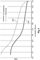
- Fig. 2 shows a diagram in which in each case the relative profile thickness is plotted over the normalized rotor radius for two different rotor blades of a wind turbine.
- the relative profile thickness namely the ratio of profile thickness to profile depth, can be specified in%, whereby it depends on the qualitative course and therefore no values are removed. Only the values for 38% and 45% are shown for orientation.
- the rotor radius here refers in each case to a rotor with at least one rotor blade mounted on a rotor hub of the rotor. The length of the respective rotor blade extends from the rotor blade root to the rotor blade tip.
- the rotor blade begins with its rotor blade root approximately at a value of 0.05 of the normalized rotor radius and ends with its rotor blade tip at the value 1 of the normalized rotor radius.
- the value of the normalized rotor radius corresponds approximately to the percentage length of the relevant rotor blade.
- the value 1 of the normalized rotor radius is equal to 100% of the rotor blade length.
- the graph 100 illustrates the profile of the relative profile thickness of a wind turbine for a low wind location and the graph 102 illustrates a profile of a wind turbine for locations with higher average wind speeds. From the graphs, it can be seen that the profile of the relative profile thickness of the graph 102 is substantially monotonously decreasing.
- Graph 102 begins in the region of the rotor blade root, that is, between a normalized rotor radius of 0.0 and 0.1 with a relative profile thickness of less than 45%. The values of the relative profile thickness decrease steadily.
- the graph 100 of the low-wind turbine starts at a significantly higher relative profile thickness. And falls only at about 15% of the normalized rotor position below the drawn 45% mark of the relative profile thickness and leaves this area only at about 50% of the normalized radius. At a normalized radial position of about 45%, the difference in the relative profile thickness between the low wind turbine of Graph 100 and the heavy wind turbine of Graph 102 is greatest.
- Fig. 3 is a diagram showing the profile depth - in the diagram simply referred to as depth - qualitatively as a function of the rotor radius, whose values are normalized to the maximum radius of the respective underlying rotor.
- the graph 200 shows the course for a low wind turbine, which is also the representation of FIG. 2 underlying, whereas the graph 202 shows the course of a strong wind turbine, which is also the FIG. 2 underlying. It can be seen that the low-wind turbine has a comparatively small depth at a very early stage, as compared to half the total radius, compared to the strong wind turbine.
- Fig. 4 shows a diagram in which the profile depths of FIG. 3 in each case the profile thickness - simplified in the diagram called thickness - is shown.
- the graphs 300 for the low-wind turbine and 402 for the high-wind turbine are shown only qualitatively above the normalized radius.
- the graphs 100, 200 and 300 on the one hand and the graphs 102, 202 and 402 are based on the same wind energy plant.
- the thickness profiles 300 and 302 are very similar for both types of plant in order to ensure the respective structural stability.
- a smaller depth is given in the outer rotor area to take into account the special conditions, such as Graph 200 of the FIG. 3 compared to graph 202. This results in the characteristic curve of the relative thickness according to graph 100 with the plateau in the range of about 40%, such as FIG. 2 shows.
- Fig. 5 shows a wind turbine 400 with a tower 402, which is built on a foundation 403.
- a nacelle 404 (nacelle) with a rotor 405 consisting essentially of a rotor hub 406 and rotor blades 407, 408 and 409 mounted thereon.
- the rotor 405 is connected to an electric generator inside the nacelle 404 for conversion coupled by mechanical work into electrical energy.
- the nacelle 404 is rotatably mounted on the tower 402, whose foundation 403 gives the necessary stability.
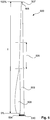
- Fig. 6 shows a side view of a rotor blade 500 of an embodiment over its entire length I, ie from 0% to 100%.
- the rotor blade 500 has a rotor blade root 504 at one end and a rotor blade tip 507 at the end remote from it.
- the rotor blade tip 507 is connected at a connection region 505 with the remaining part of the rotor blade.
- the rotor blade At the rotor blade root 504, the rotor blade has a large tread depth. In the connection area 505 and at the rotor blade tip 507, however, the tread depth is much smaller.
- the tread depth decreases, starting from the rotor blade root 504, which can also be referred to as profile root 504, to a central region 506. In the central region 506, a separation point may be provided (not shown here). From the central region 506 to the connection region 505, the tread depth is almost constant.
- the rotor blade 500 has a two-part shape in the region of the rotor blade root 504.
- the rotor blade 500 thus consists of a base profile 509, to which a further section 508 for increasing the rotor blade depth of the rotor blade 500 is arranged in the region of the rotor blade root 504.
- the section 508 is glued to the base profile 509, for example.
- Such a two-part mold is easier to handle when transporting to the site and easier to manufacture.
- FIG. 6 a hub connection area 510 can be seen. Via the hub connection region 510, the rotor blade 500 is connected to the rotor hub.
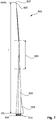
- FIG. 7 shows a further side view of the rotor blade 500 of FIG. 6 ,
- the rotor blade 500 with the base profile 509, the rotor blade depth increase section 508, the central region 506, the rotor blade root 504 and the hub connection region 510 and the connection region 505 to the rotor blade tip 507 can be seen.
- the rotor blade tip 507 is designed as a so-called winglet. As a result, vortices are reduced at the rotor blade tip.
- Fig. 1 to 7 illustrate a rotor blade or a wind turbine first without representation of the boundary layer fences and also without representation of vortex generators.
- Fig. 8 illustrates a problem that can occur with an underlying leaf of a light wind turbine.
- the illustration shows two different gradients of the local power coefficient, qualitatively plotted over the relative radius of the Rotor blade, namely the current radius r based on the maximum radius R of the underlying rotor.
- the value 1, ie 100% corresponds to the position of the blade tip and the value 0, ie 0%, to the axis of rotation of the underlying rotor. Since the sheet does not reach zero, the presentation starts at about 0.15.
- the two curves are simulation results of a three-dimensional numerical flow simulation. They show the local coefficient of performance quantitatively for two equal but differently contaminated rotor blades.
- the upper curve 700 shows the result for an essentially optimal rotor blade, which in particular has no soiling. This is always labeled “laminar-turbulent”.
- the lower curve 701 shows the result for basically the same rotor blade, but without optimal conditions, namely with soiling, which may also affect rain or raindrops on the sheet. This is in the Fig. 8 referred to as "fully turbulent".
- Fig. 9 shows a first boundary layer fence 810 and a second boundary layer fence 820. Both have a suction side section 811 and 821 and a pressure side section 812 and 822, respectively.
- Each of these sections 811, 812, 821 and 822 is designed as a web and has a base section B and a back section R, which for simplicity are designated here by the same letters in order to emphasize the functional similarity.
- Each base section B thus simultaneously identifies the profile of the blade in the respective profile section shown, namely for the suction side 801 and the pressure side 802.
- All fence sections 811, 812, 821 and 822 increase in height from an area in the vicinity of the rotor blade nose 803 Trailing edge 804 continuously closed.
- the reference numerals 801 to 804 are the same for both boundary layer fences 810 and 820 because they relate to the same rotor blade, only in the two views of Fig. 9 be shown at different radial positions.
- the Fig. 9 also shows for both boundary layer fences 810 and 820 a rotation axis 806 about which the pressure side or suction side contour is rotated in order to obtain the contour of the relevant back section R.
- This is illustrated only for the first boundary layer fence 810 and is illustrated there only for the suction side section 811, but is analogous to the pressure section 812 and also the boundary layer fence 820, viz each of the suction side portion 821 and the pressure side portion 822 mutatis mutandis transferable.
- the contour for the back section R is thus rotated by the angle of rotation ⁇ and this makes itself corresponding to the strongest at the end 808 noticeable.
- the angle of rotation ⁇ may be different for the different boundary layer sections 811, 812, 821 and 822.
- This design thus results for the fence sections a height h relative to the respective leaf surface.
- the height h changes along the respective web, ie increases from the leaf nose 803 to the trailing edge 804.
- This height h thus varies along the respective web and can also be different for the different fence sections 811, 812, 821 and 822.
- the variable h has been chosen for each fence section 811, 812, 821 and 822.
- Fig. 10 3 shows a rotor blade 800 in two views, namely a plan view of the suction side 801 and a plan view of the pressure side 802.
- the rotor blade 800 is shown from the root region 807 to the blade tip 808 and the respective plan view relates to the region of the blade tip 808 Root area 807 is twisted with respect to the blade tip area 808, which may be up to 45 to 50 °, so that the root area 807 does not appear to have the widest area, ie not the largest tread depth, but this is only a phenomenon of the perspective on this twisted area ,
- FIG. 12 shows the position of the first boundary layer fence 810 and the second boundary layer fence 820 and thus the position of the two suction side fence sections 811 and 821 and the pressure side fence sections 812 and 822.
- a rotor blade 800 of a rotor with a radius of 46 m is used.
- the first boundary layer fence 810 is arranged at a position of 15 m with respect to the radius of the rotor and the second boundary layer fence 820 is arranged at a position of 25 m.
- Fig. 10 also schematically shows a suction-side and a pressure-side position line 851 on the suction side 801 and 852 on the pressure side 802, each indicating a line along the vortex generators 853 and 854 are to be arranged.
- the vortex generators 853 and 854, which are also referred to as vortex generators, are also only indicated and can be provided in particular in a significantly higher number than shown.
- this embodiment shows vortex generators 853 on the suction side 801 only in the area between the first and second boundary layer fence 810 and 820.
- vortex generators 854 are also provided, which may be there also outside the area between the two boundary layer fences 810 and 820 to the blade root 807 out.
- FIG. 11 shows basically a section of the rotor blade 800, which essentially shows the suction side 801 of the rotor blade 800.
- the suction-side boundary layer fence sections 811 and 821 are clearly visible.
- the boundary layer fences or fence sections 821 and 811 fall out small and become larger towards the trailing edge 804, namely have a greater height than the rotor blade nose 803.
- the boundary layer fences are preferably mounted in a sheet section plane which is at a 90 ° angle to the rotor blade longitudinal axis.
- a production-related deviation thereof should not exceed a tolerance angle of 2 to 5 °, so that the end edge of the boundary layer fences, ie the area pointing to the sheet trailing edge, is not twisted more than this tolerance angle in the direction of the hub.
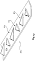
- Fig. 12 shows some vortex generators 870 in a perspective view.
- a direction of flow is indicated schematically by an arrow 872.
- the vortex generators are formed approximately triangular with a flat body, which is aligned perpendicular to the blade surface 874 and thereby obliquely to the flow direction 872 and thus is inclined to the direction of movement of the rotor blade. In this case, the inclination alternates from one vortex generator 870 to the next.
- the vortex generators have an alternating inclination to the direction of flow of the wind.
- the vortex generators also correspond in their nature and orientation about a shark fin, namely a shark fin, except that the shark fin is not oblique to the direction of flow.
- the vortex generators 870 may be applied to the rotor blade surface as a vortex generator bar 876.
- Rotor blade (1) according to embodiment 1, characterized in that the relative profile thickness (2) of the local maximum is 35% to 50%, in particular 40% to 45%.
- Rotor blade (1) according to one of embodiments 1 or 2, characterized in that the rotor blade (1) in the region of the local maximum has a tread depth of 1500 mm to 3500 mm, in particular about 2000 mm.
- Rotor blade (1) according to one of the preceding embodiments, characterized in that the rotor blade (1) is designed for a high-speed number in a range of 8 to 11, preferably from 9 to 10
- Rotor blade (1) characterized in that the rotor blade (1) in a range of 90% to 95%, the total length of the rotor blade, measured from the rotor blade root to the rotor blade tip has a tread depth (3), which is about 5% to 15%, in particular about 10%, corresponds to the tread depth (3) in the region of the rotor blade root (4) and / or that the rotor blade from 5% to 25% of the total length of the rotor blade, preferably from 5% to 35%, in particular from the rotor blade root to the central region, a linear thickness profile.
- Rotor blade (1) according to one of the preceding embodiments, characterized in that the rotor blade (1) at the rotor blade root (4) has a tread depth (3) of at least 3900 mm, in particular in a range of 3000 mm to 8000 mm, and / or in the range of 90% to 95% of the total length , in particular at 90%, starting from the rotor blade root (4), a profile depth (3) of a maximum of 1000 mm, in particular in a range of 700 mm to 300 mm.
- Rotor blade (1) according to one of the preceding embodiments, characterized in that the rotor blade (1) in the middle region has a tread depth which corresponds to about 20% to 30%, in particular about 25%, of the tread depth in the region of the rotor blade root (4)
Claims (11)
- Pale de rotor d'un rotor aérodynamique d'une éolienne comprenant :- au moins une première et une seconde clôture de couche limite (810, 820), dans laquelle-- la première clôture de couche limite (810) est disposée au niveau de la pale de rotor dans une direction radiale, par rapport à un axe de rotation du rotor, dans une plage de 25 % - 40 % du rayon du rotor, et-- la seconde clôture de couche limite (820) est disposée au niveau de la pale de rotor dans une direction radiale, par rapport à l'axe de rotation du rotor, dans une plage de 45 % - 60 % du rayon du rotor,dans laquelle la pale de rotor présente- un bord d'attaque (803) pointant à peu près dans le sens de déplacement de la pale de rotor et- un bord de fuite (804) opposé au bord d'attaque (803), et- chaque clôture de couche limite (810, 820) ou chaque section de clôture (811, 812, 821, 822) s'étendant depuis le bord d'attaque (803) vers le bord de fuite (804) augmente dans sa hauteur (h), caractérisée en ce que la clôture de couche limite (810, 820) ou la section de clôture (811, 812, 821, 822)- commence à proximité du bord d'attaque (803) avec une hauteur (h) de 0 à 5 mm et augmente jusqu'au bord de fuite (804) en continu jusqu'à une hauteur (h) supérieure à 15 mm, en particulier supérieure à 20 mm, et en ce que- la première clôture de couche limite (810) présente une hauteur (h) moyenne plus grande que la seconde clôture de couche limite (820).
- Pale de rotor selon la revendication 1, caractérisée en ce que- la première clôture de couche limite (810) est disposée au niveau de la pale de rotor dans une direction radiale, par rapport à l'axe de rotation du rotor, dans une plage de 30 % - 35 %, et/ou- la seconde clôture de couche limite (820) est disposée au niveau de la pale de rotor dans une direction radiale, par rapport à l'axe de rotation du rotor, dans une plage de 50 % - 55 %.
- Pale de rotor selon l'une quelconque des revendications précédentes, caractérisée en ce que- la première et la seconde clôture de couche limite (810, 820) sont disposées respectivement au niveau du côté aspiration (801) de la pale de rotor, ou- la première et la seconde clôture de couche limite (810, 820) présentent respectivement une section de clôture (811, 812, 821, 822) au niveau du côté aspiration (801) et du côté pression (802) de la pale de rotor.
- Pale de rotor selon l'une quelconque des revendications précédentes, caractérisée en ce que- chaque clôture de couche limite (810, 820) ou chaque section de clôture (811, 812, 821, 822) est réalisée sous la forme d'une entretoise avec- une section de base (B) et- une section arrière (R), dans laquelle- par rapport à une coupe profilée de la pale de rotor au niveau de la position de la clôture limite respective- la section de base (B) suit le profilé de pale et- la section arrière (R) suit une ligne de contour correspondant au profilé de pale, pouvant pivoter toutefois par rapport au profilé de pale, dans laquelle- la ligne de contour est pivotée d'un angle de configuration en particulier autour d'un axe de pivotement (806) s'étendant le long du bord d'attaque (803) .
- Pale de rotor selon la revendication 4, caractérisée en ce que l'angle de configuration se situe dans la plage de 1 - 3°.
- Pale de rotor selon l'une quelconque des revendications précédentes, caractérisée en ce que la clôture de couche limite présente à peu près une hauteur (h), qui correspond à l'épaisseur de la couche limite et/ou à 2 fois à 5 fois la dimension du refoulement limite dans la zone.
- Pale de rotor selon l'une quelconque des revendications précédentes, caractérisée en ce que- la hauteur (h) moyenne de la première clôture de couche limite est d'au moins 30 %, en particulier d'au moins 50 %, plus élevée que la hauteur (h) moyenne de la seconde clôture de couche limite.
- Pale de rotor selon l'une quelconque des revendications précédentes, caractérisée en ce que sont disposés, sur le côté aspiration (801) de la pale de rotor, dans le tiers avant par rapport au bord d'attaque, des générateurs de tourbillons entre la première et la seconde clôture de couche limite (810, 820), en particulier exclusivement entre la première et la seconde clôture de couche limite (810, 820).
- Pale de rotor selon l'une quelconque des revendications précédentes, caractérisée en ce que la pale de rotor est configurée pour une installation pour vents faibles et/ou présente sa plus grande profondeur de profilé directement au niveau de son pied de pale aux fins de la fixation au niveau d'un moyeu de rotor du rotor aérodynamique.
- Pale de rotor selon l'une quelconque des revendications précédentes, caractérisée en ce que sa profondeur de profilé relative, par rapport à l'axe de rotation du rotor dans une direction radiale- présente, dans une plage de 30 % - 50 %, une valeur de 35 % - 45 %, en particulier- présente, dans une plage de 35 % - 45 %, une valeur de 38 % - 45 %, et/ou- chute, dans une plage de 40 % - 55 %, en particulier 45 % - 50 %, sous une valeur de 38 %.
- Eolienne comprenant au moins une, en particulier trois, pales de rotor selon l'une quelconque des revendications précédentes.
Applications Claiming Priority (2)
| Application Number | Priority Date | Filing Date | Title |
|---|---|---|---|
| DE102013210901.6A DE102013210901A1 (de) | 2013-06-11 | 2013-06-11 | Rotorblatt einer Windenergieanlage und Windenergieanlage |
| PCT/EP2014/062100 WO2014198754A1 (fr) | 2013-06-11 | 2014-06-11 | Pale de rotor d'une éolienne et éolienne |
Publications (2)
| Publication Number | Publication Date |
|---|---|
| EP3008331A1 EP3008331A1 (fr) | 2016-04-20 |
| EP3008331B1 true EP3008331B1 (fr) | 2019-08-21 |
Family
ID=50972677
Family Applications (1)
| Application Number | Title | Priority Date | Filing Date |
|---|---|---|---|
| EP14730833.2A Active EP3008331B1 (fr) | 2013-06-11 | 2014-06-11 | Pale de rotor d'une éolienne et éolienne |
Country Status (19)
| Country | Link |
|---|---|
| US (1) | US10202963B2 (fr) |
| EP (1) | EP3008331B1 (fr) |
| JP (1) | JP6154553B2 (fr) |
| KR (1) | KR101787294B1 (fr) |
| CN (1) | CN105324577B (fr) |
| AR (1) | AR096550A1 (fr) |
| AU (1) | AU2014280202B2 (fr) |
| BR (1) | BR112015030731B1 (fr) |
| CA (1) | CA2913101C (fr) |
| CL (1) | CL2015003581A1 (fr) |
| DE (1) | DE102013210901A1 (fr) |
| DK (1) | DK3008331T3 (fr) |
| ES (1) | ES2756577T3 (fr) |
| NZ (1) | NZ714390A (fr) |
| PT (1) | PT3008331T (fr) |
| RU (1) | RU2638093C2 (fr) |
| TW (1) | TWI548811B (fr) |
| WO (1) | WO2014198754A1 (fr) |
| ZA (1) | ZA201508939B (fr) |
Families Citing this family (12)
| Publication number | Priority date | Publication date | Assignee | Title |
|---|---|---|---|---|
| PT3597902T (pt) * | 2013-09-02 | 2021-12-13 | Wobben Properties Gmbh | Gerador de vórtice para um aerogerador |
| MA40346B1 (fr) * | 2014-07-03 | 2019-07-31 | Lm Wp Patent Holding As | Pale d'éolienne |
| DE102016201114A1 (de) * | 2016-01-26 | 2017-07-27 | Wobben Properties Gmbh | Rotorblatt einer Windenergieanlage und Windenergieanlage |
| JP6856930B2 (ja) * | 2017-02-15 | 2021-04-14 | 国立研究開発法人宇宙航空研究開発機構 | ロータ、ドローン及びヘリコプタ |
| EP3587799A1 (fr) * | 2018-06-27 | 2020-01-01 | Siemens Gamesa Renewable Energy A/S | Structure aérodynamique |
| PT3587798T (pt) | 2018-06-27 | 2020-11-23 | Siemens Gamesa Renewable Energy As | Estrutura aerodinâmica |
| DE102018117398A1 (de) * | 2018-07-18 | 2020-01-23 | Wobben Properties Gmbh | Rotorblatt für eine Windenergieanlage und Windenergieanlage |
| DE102019113044A1 (de) * | 2019-05-17 | 2020-11-19 | Wobben Properties Gmbh | Verfahren zum Auslegen und Betreiben einer Windenergieanlage, Windenergieanlage sowie Windpark |
| CN110131096A (zh) * | 2019-05-28 | 2019-08-16 | 上海电气风电集团有限公司 | 一种用于风电叶片的新型涡流发生器 |
| GB202001046D0 (en) * | 2020-01-24 | 2020-03-11 | Lm Wind Power As | Wind turbine blade damping device |
| EP4027008A1 (fr) * | 2021-01-10 | 2022-07-13 | General Electric Renovables España S.L. | Pales d'éolienne avec déflecteur et procédé |
| WO2023126041A1 (fr) * | 2021-12-28 | 2023-07-06 | Vestas Wind Systems A/S | Éolienne |
Citations (1)
| Publication number | Priority date | Publication date | Assignee | Title |
|---|---|---|---|---|
| US20120051936A1 (en) * | 2011-11-02 | 2012-03-01 | Drew Eisenberg | Secondary airfoil mounted on stall fence on wind turbine blade |
Family Cites Families (12)
| Publication number | Priority date | Publication date | Assignee | Title |
|---|---|---|---|---|
| US4128363A (en) * | 1975-04-30 | 1978-12-05 | Kabushiki Kaisha Toyota Chuo Kenkyusho | Axial flow fan |
| RU2068116C1 (ru) * | 1993-03-24 | 1996-10-20 | Юрий Николаевич Данилов | Ветроколесо |
| UA54702A (uk) * | 2002-01-17 | 2003-03-17 | Володимир Юліанович Воробкевич | Лопать вітряка |
| DE10347802B3 (de) | 2003-10-10 | 2005-05-19 | Repower Systems Ag | Rotorblatt für eine Windkraftanlage |
| DE102006017897B4 (de) * | 2006-04-13 | 2008-03-13 | Repower Systems Ag | Rotorblatt einer Windenergieanlage |
| CN201771673U (zh) | 2009-12-30 | 2011-03-23 | 力仓风力设备(上海)有限公司 | 风电叶片表面之涡流发生器 |
| WO2011097024A1 (fr) * | 2010-02-02 | 2011-08-11 | Garden Energy, Inc. | Système générateur d'énergie éolienne |
| DE102010026588B4 (de) * | 2010-07-08 | 2012-06-14 | Nordex Energy Gmbh | Windenergieanlagenrotorblatt mit optimierter Hinterkante |
| US9039381B2 (en) * | 2010-12-17 | 2015-05-26 | Vestas Wind Systems A/S | Wind turbine blade and method for manufacturing a wind turbine blade with vortex generators |
| WO2012122262A2 (fr) * | 2011-03-07 | 2012-09-13 | Mcpherson Performance Blade Llc | Pale de rotor d'éolienne à performances améliorées |
| DK201170430A (en) * | 2011-08-05 | 2013-02-06 | Suzlon Blades Technology B V | Blade for a rotor of a wind turbine and a wind turbine |
| WO2013060722A1 (fr) * | 2011-10-25 | 2013-05-02 | Lm Wind Power A/S | Pale de turbine éolienne équipée d'une lame |
-
2013
- 2013-06-11 DE DE102013210901.6A patent/DE102013210901A1/de not_active Withdrawn
-
2014
- 2014-06-09 AR ARP140102213A patent/AR096550A1/es active IP Right Grant
- 2014-06-09 TW TW103119941A patent/TWI548811B/zh not_active IP Right Cessation
- 2014-06-11 RU RU2015155723A patent/RU2638093C2/ru active
- 2014-06-11 JP JP2016518983A patent/JP6154553B2/ja active Active
- 2014-06-11 CA CA2913101A patent/CA2913101C/fr active Active
- 2014-06-11 BR BR112015030731-0A patent/BR112015030731B1/pt active IP Right Grant
- 2014-06-11 KR KR1020167000418A patent/KR101787294B1/ko active IP Right Grant
- 2014-06-11 ES ES14730833T patent/ES2756577T3/es active Active
- 2014-06-11 AU AU2014280202A patent/AU2014280202B2/en not_active Ceased
- 2014-06-11 DK DK14730833T patent/DK3008331T3/da active
- 2014-06-11 US US14/897,611 patent/US10202963B2/en active Active
- 2014-06-11 CN CN201480033688.1A patent/CN105324577B/zh active Active
- 2014-06-11 EP EP14730833.2A patent/EP3008331B1/fr active Active
- 2014-06-11 NZ NZ714390A patent/NZ714390A/en not_active IP Right Cessation
- 2014-06-11 PT PT147308332T patent/PT3008331T/pt unknown
- 2014-06-11 WO PCT/EP2014/062100 patent/WO2014198754A1/fr active Application Filing
-
2015
- 2015-12-08 ZA ZA2015/08939A patent/ZA201508939B/en unknown
- 2015-12-10 CL CL2015003581A patent/CL2015003581A1/es unknown
Patent Citations (1)
| Publication number | Priority date | Publication date | Assignee | Title |
|---|---|---|---|---|
| US20120051936A1 (en) * | 2011-11-02 | 2012-03-01 | Drew Eisenberg | Secondary airfoil mounted on stall fence on wind turbine blade |
Also Published As
| Publication number | Publication date |
|---|---|
| BR112015030731A2 (pt) | 2017-07-25 |
| PT3008331T (pt) | 2019-11-27 |
| ES2756577T3 (es) | 2020-04-27 |
| BR112015030731B1 (pt) | 2022-01-18 |
| AR096550A1 (es) | 2016-01-13 |
| TW201516246A (zh) | 2015-05-01 |
| JP2016524075A (ja) | 2016-08-12 |
| WO2014198754A1 (fr) | 2014-12-18 |
| US20160138563A1 (en) | 2016-05-19 |
| AU2014280202A1 (en) | 2015-12-10 |
| CA2913101A1 (fr) | 2014-12-18 |
| CN105324577A (zh) | 2016-02-10 |
| KR101787294B1 (ko) | 2017-10-18 |
| NZ714390A (en) | 2017-01-27 |
| RU2638093C2 (ru) | 2017-12-11 |
| DK3008331T3 (da) | 2019-11-11 |
| DE102013210901A1 (de) | 2014-12-11 |
| CA2913101C (fr) | 2020-02-25 |
| KR20160017083A (ko) | 2016-02-15 |
| EP3008331A1 (fr) | 2016-04-20 |
| ZA201508939B (en) | 2017-01-25 |
| US10202963B2 (en) | 2019-02-12 |
| JP6154553B2 (ja) | 2017-06-28 |
| AU2014280202B2 (en) | 2017-02-23 |
| RU2015155723A (ru) | 2017-07-14 |
| CL2015003581A1 (es) | 2016-07-29 |
| CN105324577B (zh) | 2020-01-21 |
| TWI548811B (zh) | 2016-09-11 |
Similar Documents
| Publication | Publication Date | Title |
|---|---|---|
| EP3008331B1 (fr) | Pale de rotor d'une éolienne et éolienne | |
| EP1514023B1 (fr) | Eolienne | |
| DE10347802B3 (de) | Rotorblatt für eine Windkraftanlage | |
| EP2836702B1 (fr) | Pale d'éolienne | |
| EP2280163B1 (fr) | Eolienne et pale de rotor d'une eolienne | |
| EP2984334B1 (fr) | Pale de rotor d'éolienne et éolienne | |
| EP2004990A1 (fr) | Pale de rotor d'un dispositif d'énergie éolienne | |
| WO2012164045A1 (fr) | Rotor d'éolienne comportant une pale courbée | |
| EP3755899B1 (fr) | Pale de rotor d'une installation éolienne comprenant une plaque de déviation de la couche limite | |
| EP3169898B1 (fr) | Pale de rotor d'éolienne, bord de fuite de pointe de pale de rotor d'éolienne, procédé de fabrication d'une pale de rotor d'éolienne et éolienne | |
| EP2568166B1 (fr) | Pale de rotor d'éolienne dotée d'un rebord arrière à profil épais | |
| WO1996001368A1 (fr) | Convertisseur d'energie eolienne a axe de rotation vertical | |
| WO2014146756A1 (fr) | Pale de rotor d'une éolienne, éolienne, et procédé pour faire fonctionner une éolienne | |
| WO2020234190A1 (fr) | Pale de rotor et éolienne | |
| EP3280910A1 (fr) | Pale de rotor d'éolienne | |
| AT511895A1 (de) | Windkraftrotor in darrieus-h-bauweise und zugehörendes rotorblatt |
Legal Events
| Date | Code | Title | Description |
|---|---|---|---|
| PUAI | Public reference made under article 153(3) epc to a published international application that has entered the european phase |
Free format text: ORIGINAL CODE: 0009012 |
|
| 17P | Request for examination filed |
Effective date: 20160111 |
|
| AK | Designated contracting states |
Kind code of ref document: A1 Designated state(s): AL AT BE BG CH CY CZ DE DK EE ES FI FR GB GR HR HU IE IS IT LI LT LU LV MC MK MT NL NO PL PT RO RS SE SI SK SM TR |
|
| AX | Request for extension of the european patent |
Extension state: BA ME |
|
| STAA | Information on the status of an ep patent application or granted ep patent |
Free format text: STATUS: EXAMINATION IS IN PROGRESS |
|
| 17Q | First examination report despatched |
Effective date: 20180607 |
|
| RIC1 | Information provided on ipc code assigned before grant |
Ipc: F03D 1/06 20060101AFI20190131BHEP Ipc: B64C 11/18 20060101ALI20190131BHEP Ipc: B64C 3/14 20060101ALI20190131BHEP |
|
| GRAP | Despatch of communication of intention to grant a patent |
Free format text: ORIGINAL CODE: EPIDOSNIGR1 |
|
| STAA | Information on the status of an ep patent application or granted ep patent |
Free format text: STATUS: GRANT OF PATENT IS INTENDED |
|
| INTG | Intention to grant announced |
Effective date: 20190314 |
|
| GRAS | Grant fee paid |
Free format text: ORIGINAL CODE: EPIDOSNIGR3 |
|
| GRAJ | Information related to disapproval of communication of intention to grant by the applicant or resumption of examination proceedings by the epo deleted |
Free format text: ORIGINAL CODE: EPIDOSDIGR1 |
|
| GRAL | Information related to payment of fee for publishing/printing deleted |
Free format text: ORIGINAL CODE: EPIDOSDIGR3 |
|
| STAA | Information on the status of an ep patent application or granted ep patent |
Free format text: STATUS: EXAMINATION IS IN PROGRESS |
|
| GRAR | Information related to intention to grant a patent recorded |
Free format text: ORIGINAL CODE: EPIDOSNIGR71 |
|
| STAA | Information on the status of an ep patent application or granted ep patent |
Free format text: STATUS: GRANT OF PATENT IS INTENDED |
|
| GRAA | (expected) grant |
Free format text: ORIGINAL CODE: 0009210 |
|
| STAA | Information on the status of an ep patent application or granted ep patent |
Free format text: STATUS: THE PATENT HAS BEEN GRANTED |
|
| INTC | Intention to grant announced (deleted) | ||
| INTG | Intention to grant announced |
Effective date: 20190709 |
|
| AK | Designated contracting states |
Kind code of ref document: B1 Designated state(s): AL AT BE BG CH CY CZ DE DK EE ES FI FR GB GR HR HU IE IS IT LI LT LU LV MC MK MT NL NO PL PT RO RS SE SI SK SM TR |
|
| AX | Request for extension of the european patent |
Extension state: BA ME |
|
| REG | Reference to a national code |
Ref country code: GB Ref legal event code: FG4D Free format text: NOT ENGLISH |
|
| REG | Reference to a national code |
Ref country code: CH Ref legal event code: EP |
|
| REG | Reference to a national code |
Ref country code: DE Ref legal event code: R096 Ref document number: 502014012459 Country of ref document: DE |
|
| REG | Reference to a national code |
Ref country code: AT Ref legal event code: REF Ref document number: 1170049 Country of ref document: AT Kind code of ref document: T Effective date: 20190915 |
|
| REG | Reference to a national code |
Ref country code: IE Ref legal event code: FG4D Free format text: LANGUAGE OF EP DOCUMENT: GERMAN |
|
| REG | Reference to a national code |
Ref country code: DK Ref legal event code: T3 Effective date: 20191105 |
|
| REG | Reference to a national code |
Ref country code: NL Ref legal event code: FP |
|
| REG | Reference to a national code |
Ref country code: PT Ref legal event code: SC4A Ref document number: 3008331 Country of ref document: PT Date of ref document: 20191127 Kind code of ref document: T Free format text: AVAILABILITY OF NATIONAL TRANSLATION Effective date: 20191120 |
|
| REG | Reference to a national code |
Ref country code: SE Ref legal event code: TRGR |
|
| REG | Reference to a national code |
Ref country code: LT Ref legal event code: MG4D |
|
| PG25 | Lapsed in a contracting state [announced via postgrant information from national office to epo] |
Ref country code: FI Free format text: LAPSE BECAUSE OF FAILURE TO SUBMIT A TRANSLATION OF THE DESCRIPTION OR TO PAY THE FEE WITHIN THE PRESCRIBED TIME-LIMIT Effective date: 20190821 Ref country code: LT Free format text: LAPSE BECAUSE OF FAILURE TO SUBMIT A TRANSLATION OF THE DESCRIPTION OR TO PAY THE FEE WITHIN THE PRESCRIBED TIME-LIMIT Effective date: 20190821 Ref country code: HR Free format text: LAPSE BECAUSE OF FAILURE TO SUBMIT A TRANSLATION OF THE DESCRIPTION OR TO PAY THE FEE WITHIN THE PRESCRIBED TIME-LIMIT Effective date: 20190821 Ref country code: NO Free format text: LAPSE BECAUSE OF FAILURE TO SUBMIT A TRANSLATION OF THE DESCRIPTION OR TO PAY THE FEE WITHIN THE PRESCRIBED TIME-LIMIT Effective date: 20191121 Ref country code: BG Free format text: LAPSE BECAUSE OF FAILURE TO SUBMIT A TRANSLATION OF THE DESCRIPTION OR TO PAY THE FEE WITHIN THE PRESCRIBED TIME-LIMIT Effective date: 20191121 |
|
| PG25 | Lapsed in a contracting state [announced via postgrant information from national office to epo] |
Ref country code: IS Free format text: LAPSE BECAUSE OF FAILURE TO SUBMIT A TRANSLATION OF THE DESCRIPTION OR TO PAY THE FEE WITHIN THE PRESCRIBED TIME-LIMIT Effective date: 20191221 Ref country code: LV Free format text: LAPSE BECAUSE OF FAILURE TO SUBMIT A TRANSLATION OF THE DESCRIPTION OR TO PAY THE FEE WITHIN THE PRESCRIBED TIME-LIMIT Effective date: 20190821 Ref country code: AL Free format text: LAPSE BECAUSE OF FAILURE TO SUBMIT A TRANSLATION OF THE DESCRIPTION OR TO PAY THE FEE WITHIN THE PRESCRIBED TIME-LIMIT Effective date: 20190821 Ref country code: GR Free format text: LAPSE BECAUSE OF FAILURE TO SUBMIT A TRANSLATION OF THE DESCRIPTION OR TO PAY THE FEE WITHIN THE PRESCRIBED TIME-LIMIT Effective date: 20191122 Ref country code: RS Free format text: LAPSE BECAUSE OF FAILURE TO SUBMIT A TRANSLATION OF THE DESCRIPTION OR TO PAY THE FEE WITHIN THE PRESCRIBED TIME-LIMIT Effective date: 20190821 |
|
| PG25 | Lapsed in a contracting state [announced via postgrant information from national office to epo] |
Ref country code: TR Free format text: LAPSE BECAUSE OF FAILURE TO SUBMIT A TRANSLATION OF THE DESCRIPTION OR TO PAY THE FEE WITHIN THE PRESCRIBED TIME-LIMIT Effective date: 20190821 |
|
| REG | Reference to a national code |
Ref country code: ES Ref legal event code: FG2A Ref document number: 2756577 Country of ref document: ES Kind code of ref document: T3 Effective date: 20200427 |
|
| PG25 | Lapsed in a contracting state [announced via postgrant information from national office to epo] |
Ref country code: PL Free format text: LAPSE BECAUSE OF FAILURE TO SUBMIT A TRANSLATION OF THE DESCRIPTION OR TO PAY THE FEE WITHIN THE PRESCRIBED TIME-LIMIT Effective date: 20190821 Ref country code: EE Free format text: LAPSE BECAUSE OF FAILURE TO SUBMIT A TRANSLATION OF THE DESCRIPTION OR TO PAY THE FEE WITHIN THE PRESCRIBED TIME-LIMIT Effective date: 20190821 Ref country code: RO Free format text: LAPSE BECAUSE OF FAILURE TO SUBMIT A TRANSLATION OF THE DESCRIPTION OR TO PAY THE FEE WITHIN THE PRESCRIBED TIME-LIMIT Effective date: 20190821 Ref country code: IT Free format text: LAPSE BECAUSE OF FAILURE TO SUBMIT A TRANSLATION OF THE DESCRIPTION OR TO PAY THE FEE WITHIN THE PRESCRIBED TIME-LIMIT Effective date: 20190821 |
|
| PG25 | Lapsed in a contracting state [announced via postgrant information from national office to epo] |
Ref country code: SM Free format text: LAPSE BECAUSE OF FAILURE TO SUBMIT A TRANSLATION OF THE DESCRIPTION OR TO PAY THE FEE WITHIN THE PRESCRIBED TIME-LIMIT Effective date: 20190821 Ref country code: SK Free format text: LAPSE BECAUSE OF FAILURE TO SUBMIT A TRANSLATION OF THE DESCRIPTION OR TO PAY THE FEE WITHIN THE PRESCRIBED TIME-LIMIT Effective date: 20190821 Ref country code: CZ Free format text: LAPSE BECAUSE OF FAILURE TO SUBMIT A TRANSLATION OF THE DESCRIPTION OR TO PAY THE FEE WITHIN THE PRESCRIBED TIME-LIMIT Effective date: 20190821 Ref country code: IS Free format text: LAPSE BECAUSE OF FAILURE TO SUBMIT A TRANSLATION OF THE DESCRIPTION OR TO PAY THE FEE WITHIN THE PRESCRIBED TIME-LIMIT Effective date: 20200224 |
|
| REG | Reference to a national code |
Ref country code: DE Ref legal event code: R097 Ref document number: 502014012459 Country of ref document: DE |
|
| PLBE | No opposition filed within time limit |
Free format text: ORIGINAL CODE: 0009261 |
|
| STAA | Information on the status of an ep patent application or granted ep patent |
Free format text: STATUS: NO OPPOSITION FILED WITHIN TIME LIMIT |
|
| PG2D | Information on lapse in contracting state deleted |
Ref country code: IS |
|
| 26N | No opposition filed |
Effective date: 20200603 |
|
| PG25 | Lapsed in a contracting state [announced via postgrant information from national office to epo] |
Ref country code: SI Free format text: LAPSE BECAUSE OF FAILURE TO SUBMIT A TRANSLATION OF THE DESCRIPTION OR TO PAY THE FEE WITHIN THE PRESCRIBED TIME-LIMIT Effective date: 20190821 |
|
| PG25 | Lapsed in a contracting state [announced via postgrant information from national office to epo] |
Ref country code: MC Free format text: LAPSE BECAUSE OF FAILURE TO SUBMIT A TRANSLATION OF THE DESCRIPTION OR TO PAY THE FEE WITHIN THE PRESCRIBED TIME-LIMIT Effective date: 20190821 |
|
| REG | Reference to a national code |
Ref country code: CH Ref legal event code: PL |
|
| PG25 | Lapsed in a contracting state [announced via postgrant information from national office to epo] |
Ref country code: LU Free format text: LAPSE BECAUSE OF NON-PAYMENT OF DUE FEES Effective date: 20200611 |
|
| REG | Reference to a national code |
Ref country code: BE Ref legal event code: MM Effective date: 20200630 |
|
| PG25 | Lapsed in a contracting state [announced via postgrant information from national office to epo] |
Ref country code: CH Free format text: LAPSE BECAUSE OF NON-PAYMENT OF DUE FEES Effective date: 20200630 Ref country code: LI Free format text: LAPSE BECAUSE OF NON-PAYMENT OF DUE FEES Effective date: 20200630 Ref country code: IE Free format text: LAPSE BECAUSE OF NON-PAYMENT OF DUE FEES Effective date: 20200611 |
|
| PG25 | Lapsed in a contracting state [announced via postgrant information from national office to epo] |
Ref country code: BE Free format text: LAPSE BECAUSE OF NON-PAYMENT OF DUE FEES Effective date: 20200630 Ref country code: SE Free format text: LAPSE BECAUSE OF NON-PAYMENT OF DUE FEES Effective date: 20200612 |
|
| PG25 | Lapsed in a contracting state [announced via postgrant information from national office to epo] |
Ref country code: PT Free format text: LAPSE BECAUSE OF NON-PAYMENT OF DUE FEES Effective date: 20210412 |
|
| REG | Reference to a national code |
Ref country code: AT Ref legal event code: MM01 Ref document number: 1170049 Country of ref document: AT Kind code of ref document: T Effective date: 20200611 |
|
| REG | Reference to a national code |
Ref country code: SE Ref legal event code: EUG |
|
| PG25 | Lapsed in a contracting state [announced via postgrant information from national office to epo] |
Ref country code: AT Free format text: LAPSE BECAUSE OF NON-PAYMENT OF DUE FEES Effective date: 20200611 |
|
| PG25 | Lapsed in a contracting state [announced via postgrant information from national office to epo] |
Ref country code: MT Free format text: LAPSE BECAUSE OF FAILURE TO SUBMIT A TRANSLATION OF THE DESCRIPTION OR TO PAY THE FEE WITHIN THE PRESCRIBED TIME-LIMIT Effective date: 20190821 Ref country code: CY Free format text: LAPSE BECAUSE OF FAILURE TO SUBMIT A TRANSLATION OF THE DESCRIPTION OR TO PAY THE FEE WITHIN THE PRESCRIBED TIME-LIMIT Effective date: 20190821 |
|
| PG25 | Lapsed in a contracting state [announced via postgrant information from national office to epo] |
Ref country code: MK Free format text: LAPSE BECAUSE OF FAILURE TO SUBMIT A TRANSLATION OF THE DESCRIPTION OR TO PAY THE FEE WITHIN THE PRESCRIBED TIME-LIMIT Effective date: 20190821 |
|
| PGFP | Annual fee paid to national office [announced via postgrant information from national office to epo] |
Ref country code: NL Payment date: 20230620 Year of fee payment: 10 Ref country code: FR Payment date: 20230620 Year of fee payment: 10 Ref country code: DK Payment date: 20230621 Year of fee payment: 10 Ref country code: DE Payment date: 20221108 Year of fee payment: 10 |
|
| PGFP | Annual fee paid to national office [announced via postgrant information from national office to epo] |
Ref country code: GB Payment date: 20230622 Year of fee payment: 10 Ref country code: ES Payment date: 20230719 Year of fee payment: 10 |