WO2012164045A1 - Rotor d'éolienne comportant une pale courbée - Google Patents
Rotor d'éolienne comportant une pale courbée Download PDFInfo
- Publication number
- WO2012164045A1 WO2012164045A1 PCT/EP2012/060312 EP2012060312W WO2012164045A1 WO 2012164045 A1 WO2012164045 A1 WO 2012164045A1 EP 2012060312 W EP2012060312 W EP 2012060312W WO 2012164045 A1 WO2012164045 A1 WO 2012164045A1
- Authority
- WO
- WIPO (PCT)
- Prior art keywords
- curved
- rotor
- rotor blade
- hub
- curvature
- Prior art date
Links
- 238000011144 upstream manufacturing Methods 0.000 claims abstract description 18
- 239000000463 material Substances 0.000 claims description 12
- 229920000049 Carbon (fiber) Polymers 0.000 claims description 5
- 239000004917 carbon fiber Substances 0.000 claims description 5
- 239000003365 glass fiber Substances 0.000 claims description 3
- 238000009420 retrofitting Methods 0.000 description 5
- 238000010276 construction Methods 0.000 description 4
- 238000009825 accumulation Methods 0.000 description 3
- VNWKTOKETHGBQD-UHFFFAOYSA-N methane Chemical compound C VNWKTOKETHGBQD-UHFFFAOYSA-N 0.000 description 3
- 230000007423 decrease Effects 0.000 description 2
- 230000009471 action Effects 0.000 description 1
- 239000000853 adhesive Substances 0.000 description 1
- 230000001070 adhesive effect Effects 0.000 description 1
- 230000001174 ascending effect Effects 0.000 description 1
- 238000005452 bending Methods 0.000 description 1
- 230000008901 benefit Effects 0.000 description 1
- 230000008859 change Effects 0.000 description 1
- 230000001419 dependent effect Effects 0.000 description 1
- 230000005489 elastic deformation Effects 0.000 description 1
- 230000003993 interaction Effects 0.000 description 1
- 238000004519 manufacturing process Methods 0.000 description 1
- 230000004048 modification Effects 0.000 description 1
- 238000012986 modification Methods 0.000 description 1
- NJPPVKZQTLUDBO-UHFFFAOYSA-N novaluron Chemical compound C1=C(Cl)C(OC(F)(F)C(OC(F)(F)F)F)=CC=C1NC(=O)NC(=O)C1=C(F)C=CC=C1F NJPPVKZQTLUDBO-UHFFFAOYSA-N 0.000 description 1
- 238000005457 optimization Methods 0.000 description 1
- 238000000926 separation method Methods 0.000 description 1
- 238000003466 welding Methods 0.000 description 1
Images


Classifications
-
- F—MECHANICAL ENGINEERING; LIGHTING; HEATING; WEAPONS; BLASTING
- F03—MACHINES OR ENGINES FOR LIQUIDS; WIND, SPRING, OR WEIGHT MOTORS; PRODUCING MECHANICAL POWER OR A REACTIVE PROPULSIVE THRUST, NOT OTHERWISE PROVIDED FOR
- F03D—WIND MOTORS
- F03D1/00—Wind motors with rotation axis substantially parallel to the air flow entering the rotor
- F03D1/06—Rotors
- F03D1/0608—Rotors characterised by their aerodynamic shape
- F03D1/0633—Rotors characterised by their aerodynamic shape of the blades
-
- F—MECHANICAL ENGINEERING; LIGHTING; HEATING; WEAPONS; BLASTING
- F05—INDEXING SCHEMES RELATING TO ENGINES OR PUMPS IN VARIOUS SUBCLASSES OF CLASSES F01-F04
- F05B—INDEXING SCHEME RELATING TO WIND, SPRING, WEIGHT, INERTIA OR LIKE MOTORS, TO MACHINES OR ENGINES FOR LIQUIDS COVERED BY SUBCLASSES F03B, F03D AND F03G
- F05B2240/00—Components
- F05B2240/20—Rotors
- F05B2240/30—Characteristics of rotor blades, i.e. of any element transforming dynamic fluid energy to or from rotational energy and being attached to a rotor
- F05B2240/302—Segmented or sectional blades
-
- Y—GENERAL TAGGING OF NEW TECHNOLOGICAL DEVELOPMENTS; GENERAL TAGGING OF CROSS-SECTIONAL TECHNOLOGIES SPANNING OVER SEVERAL SECTIONS OF THE IPC; TECHNICAL SUBJECTS COVERED BY FORMER USPC CROSS-REFERENCE ART COLLECTIONS [XRACs] AND DIGESTS
- Y02—TECHNOLOGIES OR APPLICATIONS FOR MITIGATION OR ADAPTATION AGAINST CLIMATE CHANGE
- Y02E—REDUCTION OF GREENHOUSE GAS [GHG] EMISSIONS, RELATED TO ENERGY GENERATION, TRANSMISSION OR DISTRIBUTION
- Y02E10/00—Energy generation through renewable energy sources
- Y02E10/70—Wind energy
- Y02E10/72—Wind turbines with rotation axis in wind direction
Definitions
- the present invention relates to a rotor for a wind turbine, comprising a hub rotatable about a rotation axis and a number of rotor blades attached to the hub, wherein at least one rotor blade has at least one curvature portion with a curvature in the upstream direction.
- the present invention equally relates to a curved rotor blade having at least one bend portion with a curvature in a longitudinal extent for use with a rotor of the present invention.
- the achievable electrical outputs of wind turbines are limited.
- the performance of wind turbines ie their achievable electrical power, is largely dependent on the profile of your rotor blades.
- the profiles are aerodynamically shaped so that their circulation with air creates a buoyancy.
- their areas are chosen as large as possible to also increase the buoyancy.
- the maximum lift in the part-load and nominal load range is a limiting factor in the performance of wind turbines.
- the maximum achievable buoyancy of the rotor blades depends on the profile and the structural arrangement of the components of a wind turbine to each other and turns itself under certain operating conditions.
- the distance between the rotor blades and the tower affects the maximum achievable lift, as an air accumulation of the air flowing around the wind turbine between the rotor blades and tower forms.
- An authoritative operating parameter is the absolute flow velocity of the wind turbine through the wind, ie the speed with which the wind flows against the wind turbine. The limit of this operating parameter is achieved in interaction with the air accumulation, when it comes to the separation of the flow from the rotor blade. As a result, the lift decreases immediately. This results in power losses and possibly high mechanical loads on the wind turbine. Previous efforts to increase the maximum achievable lift were primarily an optimization of the profiles used. Another limit of the performance of wind turbines is given by the realizable size of profile surfaces. The profile surfaces grow depending on the rotor blade length.
- EP 1 019 631 B1 proposes that the rotor blades to be used be curved in the upstream direction. It is also contemplated in this document to tilt the nacelle from the horizontal orientation in the rotor direction towards the sky, so that the rotor blades are further spaced from the tower base. A disadvantage is stated that this results in a very unaesthetic appearance, which encounters in society on a low acceptance.
- a disadvantage of the known from EP 1 019 631 B1 device is that the curvature of the rotor blades is only suitable for wind turbines of a certain size to ensure the required distance between the rotor blades and the tower, as too large curvature of the rotor blades as aerodynamically unfavorable proves and even lead to a stall.
- the curved rotor blades from EP 1 019 631 consequently preclude an increase in the efficiency of wind power plants.
- the present invention has the object, a rotor for a wind turbine, with a hub rotatable about a rotation axis and a number of fixed to the hub rotor blades, wherein at least one rotor blade has at least one curvature portion with a curvature in the upstream direction, and a curved rotor blade to optimize the type mentioned above such that the performance of wind turbines is increased.
- the rotor-directed object is achieved by a rotor of the type mentioned, in which a extending from the hub end end base portion of the curved rotor blade is disposed with its longitudinal axis in a Vorhaltewinkel in the upstream direction to a plane orthogonal to the axis of rotation.
- the lead angle and the curvature of the rotor blades reinforce according to the invention advantageously combined in the orientation of the wind turbine in the upstream direction.
- the combination of such curved rotor blades and the lead angle more lift is generated than with rotor blades that have no curvature or are not arranged in a Vorhaltewinkel to the orthogonal plane of the axis of rotation or have neither one or the other feature of the combination.
- the lead angle may advantageously be between three degrees and four degrees, in particular three and a half degrees. However, smaller angles, e.g. 0.5 °, and larger angles, e.g. 5 °, depending on the rotor blade length and the rotor blade design possible. Also, an increase in size or length of the rotor blades described compared to conventional rotor blades later limits, since the upstream orientation of the rotor ensures a greater distance from the tower, in particular to the tower base. Conventional rotor blades are to be understood as those rotor blades which run straight over the length when no wind forces are applied to these rotor blades.
- the increase in size or length of the rotor blades and, associated therewith, the tower is a decisive factor for the performance of wind power plants, since in higher air layers the turbulences caused by the surface properties are much lower and the wind blows stronger and more evenly.
- the efficiency of wind turbines is consequently increased.
- the curved rotor blade may advantageously be about 45 meters long and set at a lead angle of three and a half degrees in the upstream direction. But there are also other rotor blade lengths executable.
- the lead angle can also be in the range of almost 0 ° to 5 °, wherein the lead angle is selected depending on the rotor blade length and the rotor blade design.
- the curved rotor blade can be designed such that under flow influence at a given flow velocity, preferably upper operating flow velocity, the curvature is substantially compensated.
- the flow velocity is understood here as the speed of the wind, with which the rotor or the rotor blades are flown during operation of the wind.
- the upper operating flow velocity is understood here as the speed of the wind, in which the curved rotor blades no longer have any curvature due to the wind forces that occur.
- the curved rotor blades are structurally designed in such a way that they are in their structurally predetermined shape when there is no wind, ie when the inflow velocity disappears, and the curvature of the curved rotor blades is compensated for by the wind forces when it flows with the upper operating inflow velocity.
- the curved rotor blades are then on a so-called zero line.
- Nennanström aus which is below the upper Radio
- the structural design of the curved rotor blades is accomplished by any means well known to those skilled in the art, e.g. the material properties and / or the mechanical construction are varied.
- the materials must be chosen such that they allow for elastic deformation and consequently no plastic deformation occurs.
- the design must take into account the respective external influencing factors based on the materials.
- a wind turbine to be built inland is sometimes subject to very different factors than a wind turbine on the high seas.
- the present invention allows the rated power of a wind turbine can be achieved over a wider range of wind speeds, since the curved rotor blades deform aerodynamically unfavorable only at higher wind speeds than conventional rotor blades. Consequently, the performance of wind turbines is increased.
- the curved rotor blade may have a variable width over the length. This allows the curved rotor blade on the one hand compensate for strength problems caused by aerodynamically necessary twists in the construction of the curved rotor blades, and on the other hand, particularly good in terms of its aerodynamic design reduce turbulence.
- the curved rotor blade can advantageously be about 2000 millimeters at its hub end and about 3500 millimeters wide at its widest point with a length of about 45 meters. In other constructive embodiments, however, the widest point may have different dimensions, e.g. up to 5500 mm.
- the base portion may be formed extending at least to one of the greatest width associated length of the curved rotor blade.
- the structural design of the base portion leads to a high strength of the entire rotor blade, whereby the rated power compared to wind turbines with conventional rotor blades over a wider range of wind speeds is achieved.
- the high strength of the pedestal section allows for less deformation by the wind compared to conventional rotor blades. As a result, longer and larger rotor blades can be used, which in turn increases the performance of wind turbines.
- the curvature section can be arranged subsequently to the base section.
- a direct connection of the curvature section to the base section has proven to be aerodynamically advantageous, since there is less mutual interference of the tower and the curved rotor blade than when using a conventional rotor blade. As a result, more lift is generated on the rotor blades, which in turn increases the performance of wind turbines.
- the curvature portion may be formed to extend to a hub facing away portion of the curved rotor blade. This leads to a greater distance between the curved rotor blade and the tower, ie less air accumulation and less interference than when using a conventional rotor blade. As a result, the rotor blades can be built larger, or longer than when using a conventional rotor blade, which also increases the performance of wind turbines.
- a substantially non-curved portion may be arranged subsequently to the curvature portion in the hub-distant direction.
- the longitudinal axis of the base portion and a longitudinal axis of the adjoining the curved portion non-curved portion may in particular at an angle of about one degree to each other.
- This angle and the lead angle can advantageously be in a ratio of one to two to one to four.
- This embodiment has proven to be aerodynamically advantageous. The buoyancy of the rotor blades is thereby increased and the performance of wind turbines is also increased.
- the curved rotor blade may have a further curved portion.
- This design is also particularly aerodynamically advantageous.
- the curvature refers to a further curvature of the curved rotor blade in the upstream direction. This increases the buoyancy of the rotor blades and increases the performance of wind turbines.
- the curved rotor blade in individual sections or all sections substantially consist of a carbon fiber and / or glass fibers containing material.
- a material has the advantage that it can be molded particularly well, is particularly lightweight and has a high rigidity. The good formability of the material makes it easy to produce the curved rotor blade.
- the defined implementation of a calculated bending line is particularly advantageous possible by the design of the curved rotor blades made of a carbon fiber material, which has proven to be particularly advantageous at wind speeds below the upper Radio Archanström für for the aerodynamics of the profile of the curved rotor blades and on reaching the upper Operating flow velocity has no more curvature.
- the high rigidity of the material also makes it possible for a wind turbine with curved rotor blades to operate even at higher wind speeds than a wind turbine with conventional rotor blades.
- the high rigidity and the low weight also make it possible to construct larger rotor blades than with other materials, since the use of carbon fibers with the same mass allows a larger area of the rotor blades to be designed.
- the curved rotor blade in individual sections or all sections substantially consist of a carbon fiber and / or glass fibers containing material.
- a material can also be formed well, is easy and inexpensive in the production and processing.
- a required stiffness of the rotor blade can be implemented constructively particularly advantageous.
- the curved rotor blade at a hub-side end have Anlegeabitese for applying the curved rotor blade to the hub, wherein a surface normal of a predetermined by the Anlegepeilen application plane with the plane orthogonal to the axis of rotation forms the lead angle.
- These Anlegeabitese serve to attach the rotor blade to the hub.
- a clearly defined contact surface between the hub and rotor blade is created, which makes it possible to fix the rotor blades in a lead angle.
- the rotor blades can consequently be aligned in accordance with the design specifications, so that the curvature of the curved rotor blades is utilized aerodynamically advantageously and a maximum of lift is achieved. This also increases the efficiency of wind turbines.
- this describes a way how to achieve the lead angle. For newly designed rotor blades this is one way to integrate the lead angle from the outset in this.
- an angle element having a surface for application to the curved rotor blade and a further surface for application to the hub, wherein the surface normals of both surfaces to each other form the lead angle.
- An angle element is particularly suitable for retrofitting to wind turbines.
- the lead angle of the rotor blades can be changed to the axis of rotation.
- a modification of the application sections of the rotor blade or a change of the hub is advantageously not necessary due to the angle element according to the invention.
- an angle element is easy to install and requires no getting used to the assembly staff compared to conventional constructions. Consequently, the aerodynamic behavior of the rotor blades can be subsequently optimized in the wind and the lift can be increased.
- the hub can Hubabelegeabschitte for applying the hub to the curved rotor blade, wherein a surface normal of a determined by the Nabenanlegeabête hub application plane with the plane orthogonal to the axis of rotation forms the lead angle.
- the Nabenanlegeabête make it possible to arrange the rotor blade and hub to each other such that the desired lead angle is achieved and the aerodynamic profile is advantageously flown. This also increases the efficiency of wind turbines.
- the object directed to a curved rotor blade is achieved by a curved rotor blade having at least one curvature portion with a curvature in a longitudinal extent for use with a rotor of the present invention, wherein the curved rotor blade at one end landing portions for applying the curved rotor blade to a hub of a Having a rotor of a wind turbine, wherein a surface normal of a predetermined by the application sections laying plane with the longitudinal axis forms a lead angle in the direction of curvature.
- a curved rotor blade has proved to be particularly aerodynamically advantageous.
- the rotor blade according to the invention with an existing hub forms an advantageous rotor, in which the curved rotor blades are arranged at a lead angle in the upstream direction to a plane orthogonal to a rotation axis.
- the object directed to a curved rotor blade is likewise achieved by a curved rotor blade according to the preamble of claim 13, which is designed so that the curvature is substantially compensated for under flow influence at a given flow velocity, preferably upper operating flow velocity, of the wind power plant.
- a given flow velocity preferably upper operating flow velocity
- the curved rotor blade forms an advantageous rotor with an existing hub.
- a curved rotor blade at one end can have application sections for applying the curved rotor blade to a hub of a rotor of a wind power plant, wherein a surface normal of a contact plane determined by the application sections forms a lead-in angle in the direction of the curvature with the longitudinal axis.
- This makes it possible to align the curved rotor blade in the lead angle, so that this is flowed aerodynamically advantageous.
- the curved rotor blade forms an advantageous rotor with an already existing hub, in which the curved rotor blades are arranged at a lead angle in the upstream direction to a plane orthogonal to a rotation axis.
- Figure 1 Schematic representation of a wind turbine in side view with a rotor according to the invention, wherein the lower half of the figure shows a state in calm weather and the upper half of the figure shows a state at a Radioanström effet;
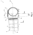
- Figure 2 front view in the wind direction on a rotor according to the invention for the wind turbine according to Figure 1 with a hub and a part of a curved rotor blade;
- FIG. 3 shows curved rotor blade according to the invention for a wind power plant according to FIG. 1, FIG. 3a) showing the curved rotor blade in the direction of arrow IIIa in FIG. 2 and FIG. 3b) showing a frontal view of the blade of the curved rotor blade shown in FIG.
- FIG. 4 profile cross sections through the curved rotor blade according to the invention in different rotor blade lengths
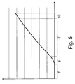
- FIG. 5 Curvature profile of the curved rotor blade according to FIG. 4 relative to the rotor blade length in a splayed coordinate system.
- Figure 1 shows a schematic representation of a wind turbine 2 in with a rotor 1 according to the invention, wherein the lower half of the figure shows a state in calm weather and the upper half of the figure shows a state at a Billanström york.
- the wind turbine 2 has a tower 3, a machine house 4, the rotor 1, a hub 6 and a number of curved rotor blades 5, 5a.
- the machine house 4 is arranged on the tower 3.
- the rotor 1 is arranged on the machine house 4.
- the rotor 1 comprises two curved rotor blades 5, 5a and a hub 6. Furthermore, in FIG.
- a curved rotor blade 5a of the same design as the curved rotor blade 5 is shown, which has been impinged by the wind at an upper operating inflow velocity.
- the curvature of the rotor blade 5 is compensated by the action of the wind, so that the rectilinear rotor blade 5a is present.
- the rotor blade 5a consequently lies on the longitudinal axis 14 of the base section 7. Furthermore, it can be seen in this state that the base section 7 increases in width away from the hub 6. At the point at which the curved rotor blade 5 is widest, the base portion 7 ends and it follows a curvature section 8.
- the curvature section 8 is adjoined in turn by a substantially non-curved section 9.
- the non-curved portion 9 is followed by a hub facing away portion 10, which has a further curved portion.
- the curved rotor blade 5 does not lie in the plane 16 orthogonal to the axis of rotation 15, even at the upper operating flow velocity, since the curved rotor blade 5 is arranged at a lead angle 11 to the hub 6.
- the lead angle 11 is about three and a half degrees.
- the hub application sections are arranged at the hub 6 at the lead angle 11.
- an angle member between the curved rotor blade 5 and the hub 6 is provided.
- This angle element has two contact sections, the first of which are connected to the curved rotor blade 5 and the second with the hub 6 and are below the Vorhaltewinkel 11 to each other.
- the curved rotor blade 5 on Anlegeabête which are aligned at the angle 11 to the orthogonal plane of the longitudinal axis 14 of the base portion 7.
- the angle element which is particularly suitable for retrofitting to existing wind turbines 2
- the other two options are preferably to choose in new constructions.
- the viewing direction of the wind turbine in FIG. 2 is indicated by an arrow II.
- Figure 2 shows a front view of a rotor according to the invention for the wind turbine according to Figure 1 with a hub and a part of a curved rotor blade in the direction of arrow II in Figure 1. It is a detail view of Figure 1.
- the hub 6 By the hub 6 is the axis of rotation 15 drawn.
- the curved rotor blade 5 By the curved rotor blade 5, of which only a part of the base portion 7 can be seen, the longitudinal axis 14 of the base portion 7 is drawn.
- another lead angle 11a is seen between the rotation axis 15 of the hub 6 and the hub application portion 12, which is equal in magnitude to the lead angle 11. The angle is about three and a half degrees. It can be seen that the lead angle 11 is given by the hub 6.
- the hub application section 12 sweeps over a conical jacket.
- the hub 6 and the curved rotor blade 5 are connected to each other by means of screw. But there are also welding, riveting and adhesive joints conceivable. It can also be seen with reference to FIG. 2 that the hub has 6 threaded bores for a screw connection to the machine house 4.
- FIG. 3 shows a curved rotor blade according to the invention for a wind power plant according to FIG. 1, FIG. 3 a) showing the curved rotor blade in the direction of arrow III a in FIG. 2 and FIG. 3 b) showing a frontal view of the blade of the curved rotor blade illustrated in FIG. Both in FIG. 3a) and in FIG. 3b), a coordinate system with grid lines is shown for orientation.
- FIG. 3 a) the length of the curved rotor blade 5 is plotted along the abscissa, and the width of the curved rotor blade 5 is plotted along the ordinate. From the hub-side end, on the left in the view a), the width increases to a point of greatest width 17.
- This area from the hub-side end to the point of greatest width 17 is the base section 7.
- a curved section 8 adjoins the base section 7.
- a substantially non-curved section 9 adjoins this curved section 8.
- At this non-curved portion 9 is followed by a hub facing away portion 10, which has a further curved portion.
- FIG. 3 b) is a view of FIG. 3 a rotated by 90 °, wherein one does not see the cross section of the curved rotor blade 5.
- the length of the curved rotor blade 5 is plotted along the abscissa, and the thickness of the curved rotor blade 5 is plotted along the ordinate.
- the wind direction from which the rotor 1 is impinged is also shown. It runs in the ordinate direction.
- the base section 7 merges into a curved section 8.
- the curved rotor blade 5 is inclined upstream, ie in the negative ordinate direction.
- the rotor blade 5 is deflected at its tip in relation to the abscissa in approximately half the amount of the thickness of the hub-side end in the upstream direction.
- FIG. 4 shows profile cross sections 18, 210-217 through the curved rotor blade according to the invention in different rotor blade lengths.
- the abscissa shows the width and the ordinate the thickness.
- the wind direction, from which the rotor 1 is flown, is also shown. It runs in the ordinate direction.
- the circle 18 shows the cross section of the curved rotor blade 5 at its hub end.
- the further profile cross-sections 210-217 show that the profile cross-section initially increases up to a maximum value in the direction away from the hub and then decreases. This is indicated by the ascending numbering of their reference numerals 210-217.
- FIG. 5 shows the curvature profile of the curved rotor blade according to FIG. 4 along the longitudinal deflection of the rotor blade.
- the abscissa represents the length of the curved rotor blade 5 and the ordinate represents a curvature of the curved rotor blade 5 in the upstream direction.
- the scales on the abscissa and on the ordinate are different.
- the curvature of the curved rotor blade 5 in the ordinate direction is shown heavily oversubscribed. Starting from the point of intersection of the abscissa and the ordinate, it is easy to see a straight line, followed by a curvature. This straight line corresponds to the base section 7.
- the curvature shown corresponds to the curved section 8 of the rotor blade 5 and extends only over a short section.
- a non-curved section 9 adjoins this curved section 8.
- This non-curved portion 9 terminates at the hub facing away from section 10.
- This hub facing away portion 10 is a further curved portion.
Abstract
Priority Applications (3)
| Application Number | Priority Date | Filing Date | Title |
|---|---|---|---|
| US14/123,058 US20140234108A1 (en) | 2011-05-31 | 2012-05-31 | Rotor with a curved rotor blade for a wind power plant |
| CA2837963A CA2837963A1 (fr) | 2011-05-31 | 2012-05-31 | Rotor d'eolienne comportant une pale courbee |
| EP12725388.8A EP2715117A1 (fr) | 2011-05-31 | 2012-05-31 | Pale courbé du rotor d'une eolienne |
Applications Claiming Priority (2)
| Application Number | Priority Date | Filing Date | Title |
|---|---|---|---|
| DE102011050777.9 | 2011-05-31 | ||
| DE102011050777A DE102011050777A1 (de) | 2011-05-31 | 2011-05-31 | Rotor und Rotorblatt für eine Windkraftanlage |
Publications (2)
| Publication Number | Publication Date |
|---|---|
| WO2012164045A1 true WO2012164045A1 (fr) | 2012-12-06 |
| WO2012164045A9 WO2012164045A9 (fr) | 2014-01-30 |
Family
ID=46208020
Family Applications (1)
| Application Number | Title | Priority Date | Filing Date |
|---|---|---|---|
| PCT/EP2012/060312 WO2012164045A1 (fr) | 2011-05-31 | 2012-05-31 | Rotor d'éolienne comportant une pale courbée |
Country Status (5)
| Country | Link |
|---|---|
| US (1) | US20140234108A1 (fr) |
| EP (1) | EP2715117A1 (fr) |
| CA (1) | CA2837963A1 (fr) |
| DE (1) | DE102011050777A1 (fr) |
| WO (1) | WO2012164045A1 (fr) |
Cited By (2)
| Publication number | Priority date | Publication date | Assignee | Title |
|---|---|---|---|---|
| EP2761170B1 (fr) | 2012-01-25 | 2017-03-08 | Siemens Aktiengesellschaft | Pale de turbine éolienne ayant une forme de courbure géométrique |
| TWI640686B (zh) * | 2015-07-22 | 2018-11-11 | 日立製作所股份有限公司 | Wind power generation device and wireless communication method in wind power generation device |
Families Citing this family (7)
| Publication number | Priority date | Publication date | Assignee | Title |
|---|---|---|---|---|
| US20150118051A1 (en) * | 2013-10-30 | 2015-04-30 | Richard A. Steinke | Wind sail receptor |
| DE102016012060A1 (de) * | 2016-09-29 | 2018-03-29 | Guido Becker | Windkraftanlage |
| CN106515044B (zh) * | 2016-10-25 | 2019-07-16 | 北京金风科创风电设备有限公司 | 叶片模具的阳模及其修改方法、叶片预弯的调整方法 |
| CN106593761B (zh) * | 2016-12-19 | 2020-06-23 | 北京金风科创风电设备有限公司 | 叶片及包括叶片的风力发电机、阳模及制造阳模的方法 |
| DE102018005965A1 (de) * | 2018-07-30 | 2020-01-30 | Senvion Gmbh | Rotorblatt für eine windenergieanlage, windenergieanlage; verfahren zum verlängern eines rotorblatts sowie verfahren zum herstellen eines rotorblatts |
| US11149709B2 (en) * | 2018-09-24 | 2021-10-19 | General Electric Company | Method to reduce noise and vibration in a jointed wind turbine blade, and associated wind turbine blade |
| CN114704439B (zh) * | 2022-06-07 | 2022-08-19 | 东方电气风电股份有限公司 | 一种风力发电机组叶片扭转变形在线监测方法 |
Citations (9)
| Publication number | Priority date | Publication date | Assignee | Title |
|---|---|---|---|---|
| EP1019631A1 (fr) | 1997-09-04 | 2000-07-19 | Lm Glasfiber A/S | Rotor d'eolienne et pales correspondantes |
| WO2003060319A1 (fr) * | 2002-01-18 | 2003-07-24 | Aloys Wobben | Element intermediaire monte a la base d'une pale d'eolienne destine a augmenter l'ecart entre l'extremite de la pale et la tour |
| EP1596063A2 (fr) * | 2004-05-11 | 2005-11-16 | REpower Systems AG | Eolienne avec pales de rotor courbées |
| US20060067828A1 (en) * | 2004-09-29 | 2006-03-30 | Wetzel Kyle K | Wind turbine rotor blade with in-plane sweep and devices using same, and method for making same |
| WO2008064678A2 (fr) * | 2006-11-27 | 2008-06-05 | Lm Glasfiber A/S | Inclinaison de pales pour aérogénérateur |
| EP1953383A1 (fr) * | 2005-10-28 | 2008-08-06 | Gamesa Innovation & Technology, S.L. | Pale fendue pour eoliennes |
| DE102009025927A1 (de) * | 2008-06-06 | 2009-12-10 | General Electric Co. | Rotoranordnung für eine Windkraftanlage und Verfahren zum Zusammenbau derselben |
| EP2169217A1 (fr) * | 2007-02-28 | 2010-03-31 | Gamesa Innovation&technology, S.L. | Pale pour éoliennes |
| WO2011134810A1 (fr) * | 2010-04-26 | 2011-11-03 | Suzlon Blade Technology B.V. | Rotor pour éolienne |
Family Cites Families (10)
| Publication number | Priority date | Publication date | Assignee | Title |
|---|---|---|---|---|
| FR2768121B1 (fr) * | 1997-09-10 | 1999-11-19 | Onera (Off Nat Aerospatiale) | Pale a signature sonore reduite, pour voilure tournante d'aeronef, et voilure tournante comportant une telle pale |
| DK177128B1 (da) * | 2003-07-10 | 2011-12-19 | Lm Glasfiber As | Transport og opbevaring af forkrumme vindmøllevinger |
| DE202006013519U1 (de) * | 2006-08-29 | 2006-12-21 | Euros Entwicklungsgesellschaft für Windkraftanlagen mbH | Windenergieanlage mit konusförmig angeordneten Rotorblättern |
| DE102006053712A1 (de) * | 2006-11-15 | 2008-05-21 | Nordex Energy Gmbh | Rotorblatt und Windkraftanlage |
| US20090324416A1 (en) * | 2008-06-30 | 2009-12-31 | Ge Wind Energy Gmbh | Wind turbine blades with multiple curvatures |
| US8562300B2 (en) * | 2009-09-14 | 2013-10-22 | Hamilton Sundstrand Corporation | Wind turbine with high solidity rotor |
| US8696315B2 (en) * | 2010-08-16 | 2014-04-15 | General Electric Company | Hub for a wind turbine and method of mounting a wind turbine |
| EP2613047B1 (fr) * | 2010-08-31 | 2018-07-11 | Mitsubishi Heavy Industries, Ltd. | Méthode de conception d'un rotor d'éolienne, dispositif d'assistance à la conception d'un rotor d'éolienne et programme d'assistance à la conception d'un rotor d'éolienne |
| US8317483B2 (en) * | 2010-12-15 | 2012-11-27 | General Electric Company | Wind turbine rotor blade |
| US9109578B2 (en) * | 2012-06-12 | 2015-08-18 | General Electric Company | Root extender for a wind turbine rotor blade |
-
2011
- 2011-05-31 DE DE102011050777A patent/DE102011050777A1/de not_active Withdrawn
-
2012
- 2012-05-31 WO PCT/EP2012/060312 patent/WO2012164045A1/fr active Application Filing
- 2012-05-31 US US14/123,058 patent/US20140234108A1/en not_active Abandoned
- 2012-05-31 EP EP12725388.8A patent/EP2715117A1/fr not_active Withdrawn
- 2012-05-31 CA CA2837963A patent/CA2837963A1/fr not_active Abandoned
Patent Citations (10)
| Publication number | Priority date | Publication date | Assignee | Title |
|---|---|---|---|---|
| EP1019631A1 (fr) | 1997-09-04 | 2000-07-19 | Lm Glasfiber A/S | Rotor d'eolienne et pales correspondantes |
| EP1019631B1 (fr) | 1997-09-04 | 2004-12-29 | Lm Glasfiber A/S | Rotor d'eolienne et pales correspondantes |
| WO2003060319A1 (fr) * | 2002-01-18 | 2003-07-24 | Aloys Wobben | Element intermediaire monte a la base d'une pale d'eolienne destine a augmenter l'ecart entre l'extremite de la pale et la tour |
| EP1596063A2 (fr) * | 2004-05-11 | 2005-11-16 | REpower Systems AG | Eolienne avec pales de rotor courbées |
| US20060067828A1 (en) * | 2004-09-29 | 2006-03-30 | Wetzel Kyle K | Wind turbine rotor blade with in-plane sweep and devices using same, and method for making same |
| EP1953383A1 (fr) * | 2005-10-28 | 2008-08-06 | Gamesa Innovation & Technology, S.L. | Pale fendue pour eoliennes |
| WO2008064678A2 (fr) * | 2006-11-27 | 2008-06-05 | Lm Glasfiber A/S | Inclinaison de pales pour aérogénérateur |
| EP2169217A1 (fr) * | 2007-02-28 | 2010-03-31 | Gamesa Innovation&technology, S.L. | Pale pour éoliennes |
| DE102009025927A1 (de) * | 2008-06-06 | 2009-12-10 | General Electric Co. | Rotoranordnung für eine Windkraftanlage und Verfahren zum Zusammenbau derselben |
| WO2011134810A1 (fr) * | 2010-04-26 | 2011-11-03 | Suzlon Blade Technology B.V. | Rotor pour éolienne |
Cited By (3)
| Publication number | Priority date | Publication date | Assignee | Title |
|---|---|---|---|---|
| EP2761170B1 (fr) | 2012-01-25 | 2017-03-08 | Siemens Aktiengesellschaft | Pale de turbine éolienne ayant une forme de courbure géométrique |
| US9920741B2 (en) | 2012-01-25 | 2018-03-20 | Siemens Aktiengesellschaft | Wind turbine blade having a geometric sweep |
| TWI640686B (zh) * | 2015-07-22 | 2018-11-11 | 日立製作所股份有限公司 | Wind power generation device and wireless communication method in wind power generation device |
Also Published As
| Publication number | Publication date |
|---|---|
| EP2715117A1 (fr) | 2014-04-09 |
| DE102011050777A1 (de) | 2012-12-06 |
| WO2012164045A9 (fr) | 2014-01-30 |
| CA2837963A1 (fr) | 2012-12-06 |
| US20140234108A1 (en) | 2014-08-21 |
Similar Documents
| Publication | Publication Date | Title |
|---|---|---|
| WO2012164045A1 (fr) | Rotor d'éolienne comportant une pale courbée | |
| EP2339171B1 (fr) | Pale pour une éolienne | |
| EP3330530B1 (fr) | Pale d'éolienne | |
| EP3008331B1 (fr) | Pale de rotor d'une éolienne et éolienne | |
| DE102009025857A1 (de) | Windmaschinenrotorflügel-Grundrisse mit verdrehten und sich verjüngenden Spitzen | |
| EP3066337B1 (fr) | Pale de rotor d'une éolienne et éolienne | |
| EP2984334B1 (fr) | Pale de rotor d'éolienne et éolienne | |
| EP2284389A2 (fr) | Pale de rotor d'une eolienne | |
| EP3399183B1 (fr) | Pale de rotor d'une éolienne | |
| EP2976524B1 (fr) | Pale de rotor d'une éolienne, éolienne, et procédé pour faire fonctionner une éolienne | |
| DE102019119027B4 (de) | Rotorblatt und Windenergieanlage | |
| EP3824176A1 (fr) | Pale de rotor pour éolienne et éolienne | |
| DE202018006764U1 (de) | Verwirbelungselement | |
| WO2014090219A2 (fr) | Pale de rotor, bras de retenue et rotor pour éolienne à axe vertical, procédé de production et éolienne à axe vertical | |
| EP3969743A1 (fr) | Pale de rotor et éolienne | |
| EP3464892B1 (fr) | Éolienne avec une tour avec un profil aérodynamique | |
| DE19807193C1 (de) | Windkraftanlage in Schnelläuferausführung | |
| EP3969741B1 (fr) | Pale de rotor et éolienne | |
| WO2016162350A1 (fr) | Pale de rotor d'éolienne | |
| DE102008035058A1 (de) | Rotorblatt und Windkraftanlage damit | |
| EP4227522A1 (fr) | Pale de rotor, éolienne, angle de dentelure, paramètre environnemental | |
| WO2020221860A1 (fr) | Rotor pour une éolienne et éolienne | |
| EP3954892A2 (fr) | Pale de rotor pour une éolienne, rotor pour une éolienne, construction et éolienne | |
| DE102019112945A1 (de) | Windenergieanlage und Windenergieanlagen-Rotorblatt | |
| EP3735530A1 (fr) | Pale de rotor pour éolienne et procédé |
Legal Events
| Date | Code | Title | Description |
|---|---|---|---|
| 121 | Ep: the epo has been informed by wipo that ep was designated in this application |
Ref document number: 12725388 Country of ref document: EP Kind code of ref document: A1 |
|
| REEP | Request for entry into the european phase |
Ref document number: 2012725388 Country of ref document: EP |
|
| WWE | Wipo information: entry into national phase |
Ref document number: 2012725388 Country of ref document: EP |
|
| ENP | Entry into the national phase |
Ref document number: 2837963 Country of ref document: CA |
|
| WWE | Wipo information: entry into national phase |
Ref document number: 14123058 Country of ref document: US |