EP1619703B1 - Folientastatur und Herstellungsmethode - Google Patents
Folientastatur und Herstellungsmethode Download PDFInfo
- Publication number
- EP1619703B1 EP1619703B1 EP05015521A EP05015521A EP1619703B1 EP 1619703 B1 EP1619703 B1 EP 1619703B1 EP 05015521 A EP05015521 A EP 05015521A EP 05015521 A EP05015521 A EP 05015521A EP 1619703 B1 EP1619703 B1 EP 1619703B1
- Authority
- EP
- European Patent Office
- Prior art keywords
- key sheet
- base plate
- hard base
- operating portions
- keytops
- Prior art date
- Legal status (The legal status is an assumption and is not a legal conclusion. Google has not performed a legal analysis and makes no representation as to the accuracy of the status listed.)
- Expired - Lifetime
Links
Images


Classifications
-
- H—ELECTRICITY
- H01—ELECTRIC ELEMENTS
- H01H—ELECTRIC SWITCHES; RELAYS; SELECTORS; EMERGENCY PROTECTIVE DEVICES
- H01H13/00—Switches having rectilinearly-movable operating part or parts adapted for pushing or pulling in one direction only, e.g. push-button switch
- H01H13/70—Switches having rectilinearly-movable operating part or parts adapted for pushing or pulling in one direction only, e.g. push-button switch having a plurality of operating members associated with different sets of contacts, e.g. keyboard
- H01H13/88—Processes specially adapted for manufacture of rectilinearly movable switches having a plurality of operating members associated with different sets of contacts, e.g. keyboards
-
- H—ELECTRICITY
- H01—ELECTRIC ELEMENTS
- H01H—ELECTRIC SWITCHES; RELAYS; SELECTORS; EMERGENCY PROTECTIVE DEVICES
- H01H2209/00—Layers
- H01H2209/006—Force isolators
-
- H—ELECTRICITY
- H01—ELECTRIC ELEMENTS
- H01H—ELECTRIC SWITCHES; RELAYS; SELECTORS; EMERGENCY PROTECTIVE DEVICES
- H01H2209/00—Layers
- H01H2209/01—Increasing rigidity; Anti-creep
-
- H—ELECTRICITY
- H01—ELECTRIC ELEMENTS
- H01H—ELECTRIC SWITCHES; RELAYS; SELECTORS; EMERGENCY PROTECTIVE DEVICES
- H01H2209/00—Layers
- H01H2209/068—Properties of the membrane
- H01H2209/082—Properties of the membrane transparent
-
- H—ELECTRICITY
- H01—ELECTRIC ELEMENTS
- H01H—ELECTRIC SWITCHES; RELAYS; SELECTORS; EMERGENCY PROTECTIVE DEVICES
- H01H2223/00—Casings
- H01H2223/034—Bezel
- H01H2223/0345—Bezel with keys positioned directly next to each other without an intermediate bezel or frame
-
- H—ELECTRICITY
- H01—ELECTRIC ELEMENTS
- H01H—ELECTRIC SWITCHES; RELAYS; SELECTORS; EMERGENCY PROTECTIVE DEVICES
- H01H2227/00—Dimensions; Characteristics
- H01H2227/036—Minimise height
-
- H—ELECTRICITY
- H01—ELECTRIC ELEMENTS
- H01H—ELECTRIC SWITCHES; RELAYS; SELECTORS; EMERGENCY PROTECTIVE DEVICES
- H01H2229/00—Manufacturing
- H01H2229/044—Injection moulding
- H01H2229/048—Insertion moulding
Definitions
- the present invention relates to a pushbutton switch key sheet for use in an operating portion of various apparatuses, such as a mobile phone, a personal digital assistant (PDA), a car navigation apparatus, or a car audio apparatus, and more particularly to a key sheet having keytops on a rigid base sheet.
- various apparatuses such as a mobile phone, a personal digital assistant (PDA), a car navigation apparatus, or a car audio apparatus, and more particularly to a key sheet having keytops on a rigid base sheet.
- a base sheet is formed such that a plurality of through-holes are formed in a thin hard resin plate, and each of the through-holes is covered with a thin-walled operating portion consisting of a rubber-like elastic material.
- a keytop is fixed to each operating portion by an adhesive or the like, thus a key sheet is formed (See JP 2003-178639 A , the first embodiment (paragraph 0014, Fig. 1 )).
- This conventional key sheet has a problem in that its molding takes effort, resulting in a rather high cost. That is, to manufacture the base sheet, it is necessary to form in the mold an inlet for the rubber-like elastic material corresponding to each through-hole of the hard resin plate. After molding, it is also necessary to perform gate cutting for each through-hole. This leads to a rather complicated mold structure, resulting in high cost and an increase in operational burden after molding.
- the operating portions are formed by injection molding using a rubber-like elastic material such as a thermoplastic elastomer
- a rubber-like elastic material such as a thermoplastic elastomer
- the keytops which are attached by adhesive or the like
- the contact switch of the printed circuit board is turned on/off by the molding marks at the time of depression of the keytops, so there is a fear of accurate depressing operation being hindered.
- the existence of the molding marks in the operating portions leads to unevenness in illumination of the keytops, so there is also a fear of the outward appearance of the key sheet when the illumination as been impaired.
- this conventional key sheet however, the rubber-like elastic material film covers one surface of the hard resin plate, which means that the thickness of the rubber-like elastic material film is added to the thickness of the hard resin plate, with the result that the thickness of the base sheet as a whole increases.
- this conventional key sheet is not applicable to an apparatus of which a reduction in thickness on the order of millimeters or less is required, as in the case of an electronic device.
- WO 2005/093 770 A1 which is a document under Art. 54(3) EPC, discloses a cover member for a pushbutton switch capable of reducing impact on a hard base and the effects of deformation of the hard base on a circuit board.
- the present invention provides a key sheet according to claim 1.
- the key sheet is formed such that the upper surfaces of the operating portions elastically supporting the keytops are formed at in-hole positions that are lower than the surface of the hard base plate.
- the keytops are fixed to the operating portions through the intermediation of adhesion layers, it is possible to reduce the height of the fixed keytops since the upper surfaces of the operating portions are at in-hole positions that are one step lower than the surface of the hard base plate, thus making it possible to achieve a reduction in the thickness of the key sheet.
- the connecting portion may be formed so as to be within the thickness of the hard base plate.
- the connecting portion does not protrude from the surface of the hard base plate, so it is possible to achieve a reduction in the thickness of the key sheet.
- the above-described key sheet has a molding mark on the connecting portion.
- the molding mark is on the connecting portion and on none of the operating portions.
- the key sheet of the present invention is formed as an illumination type key sheet, it is also possible to prevent unevenness in the illumination of the keytops due to molding marks on the operating portions.
- a recess is formed in the connecting portion, and a molding mark exists in the recess.
- the connecting portion and the operating portions are formed by injection molding of a thermoplastic elastomer, which leaves a relatively large molding mark, the molding mark remains within the depth of the recess, and does not protrude beyond the surface of the base sheet.
- the key sheet can be installed on the printed circuit board of an apparatus in a stable attitude without involving looseness with respect to the printed circuit board.
- a plurality of operating portions and a connecting portion are formed of a translucent rubber-like elastic material, and recesses for accommodating inner light sources to be provided on the apparatus are formed in the connecting portion.
- the light emitted from the inner light sources is guided from the translucent connecting portion to the operating portions, making it possible to brightly illuminate the keytops.
- the accommodating recesses have molding marks. In this construction, even if the connecting portion and the operating portions are formed through injection molding of a thermoplastic elastomer, which leaves a relatively large molding mark, no molding mark protrudes beyond the surface of the base sheet due to the depth of the accommodating recesses and the inner light sources. As a result, the key sheet can be installed on the printed circuit board of an apparatus without involving looseness.
- the present invention provides a key sheet manufacturing method according to claim 12.
- This key sheet manufacturing method includes the steps of: forming a hard base plate having a plurality of through-holes and a communicating groove leading to the plurality of through-holes; and integrally forming on a hard base plate a plurality of operating portions and a connecting portion connecting the operating portions with each other by pouring a rubber-like elastic material into an inlet of a mold having the inlet at a position corresponding to one of the through-holes or a position corresponding to the communicating groove.
- a plurality of operating portions are integrally formed through the connecting portion of the communicating groove, so that there is no need to cover the front surface or back surface of the hard base plate with a rubber-like elastic material, making it possible to manufacture a thin key sheet.
- the molding mark exists on the connecting portion and on none of the operating portions, so there is no disadvantage of the keytops being obliquely fixed to thereby impair the outward appearance of the key sheet due to protrusion of molding marks on the upper surfaces of the operating portions, or of the contact switch being erroneously turned on due to protrusion of molding marks on the lower surfaces of the operating portions.
- the key sheet obtained by this manufacturing method is formed as an illumination type key sheet, the key sheet can be one that is free from unevenness in illumination of the keytops due to molding marks on the operating
- various types of molding methods such as injection molding, compression molding, and transfer molding, are applicable according to the type of selected rubber-like elastic material forming the operating portions, etc.
- the two-color molding method is also applicable to the step of molding the hard base plate and the step of molding the operating portions, etc. of the key sheet manufacturing method described above.
- the communicating groove of the hard base plate in each aspect of the present invention described above is formed as a bottomed groove by partially removing the thickness of the hard base plate, or as a hole-shaped groove extending through the thickness of the hard base plate.
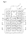
- the key sheet in each aspect of the present invention described above may be formed as a small-pitch key sheet in which a plurality of closely arranged keytops are collectively exposed through a single opening with no partition frame provided in the casing of an apparatus.
- the casing since the casing has no partition frame, it is possible to make the keytop operating surfaces so much the larger, thereby achieving an improvement in terms of operability.
- the key sheet and the key sheet manufacturing method of the present invention it is possible to achieve a reduction in production cost through simplification of the mold structure although the base sheet is thin, so it is possible to realize a key sheet which is superior in thinness at low cost. Further, it is possible to realize a key sheet superior not only in thinness but also in outward appearance and operability at low cost.
- a key sheet 11 of the first embodiment is of a type in which keytops 12 are exposed through individual operation openings 3 formed in a casing 2 of an electronic device 1.
- This electronic device 1 being a mobile phone, a PDA, a car navigation apparatus, or a car audio apparatus, or any other electronic device having a pushbutton switch key sheet is within the scope of the present invention.
- the key sheet 11 is composed of a plurality of keytops 12 and a base sheet 13. Of these, the keytops 12 are fixed to the base sheet 13 through the intermediation of adhesion layers 14 ( Fig. 3 ).
- the material of the keytops 12 is one which is entirely or partially translucent. In this case, the material of the adhesion layer 14 is also translucent. In particular, the material of the adhesion layer 14 is colorless and transparent.
- the base sheet 13 is equipped with a hard base plate 15 formed of a translucent hard resin as a base.
- the hard base plate 15 is composed of an annular outer frame portion 16 and a lattice-like inner frame portion 17 extending on the inner side of the annular outer frame portion 16.
- a holding/receiving portion 18 formed of a rubber-like elastic material.
- the back surface of the casing 2 of the electronic device 1 and a printed circuit board 4 are contained in the casing 2 pressurize and hold the holding/receiving portion 18 therebetween, whereby the key sheet 11 is attached to the electronic device 1.
- inner frame portion 17 Formed in the inner frame portion 17 are a plurality of accommodation recesses 17a, where there are accommodated inner light sources 5, such as chip light-emitting diodes (LEDs), protruding from the printed circuit board 4 of the electronic device 1.
- inner light sources 5 such as chip light-emitting diodes (LEDs)
- a plurality of through-holes 19 defined by the outer frame portion 16 and the inner frame portion 17 in correspondence with the fixing positions of the keytops 12.
- bottomed communicating grooves 17b are formed by partially reducing the plate thickness.
- the through-holes 19 are blocked by operating portions 20 formed of a rubber-like elastic material and adapted to floatingly support the keytops 12 so as to allow displacement under pressurization.
- the adjacent operating portion 20 is formed serially and integrally through connecting portions 21 filling the communicating grooves 17b.
- the upper surfaces of the operating portions 20 are situated within the through-holes 19, and are one step lower than the surface of the hard base plate 15.
- the keytops 12 are fixed to these upper surfaces, which are one step lower, through the intermediation of adhesion layers 14 formed within these upper surfaces.
- the material of the hard base plate 15 of the base sheet 13 is rigid enough not to cause the key sheet 11 to be bent by the weight of the keytops 12 even when the electronic device 1 is set upright, or it is placed obliquely or with the keytop 12 side thereof facing downwards.
- the materials for the hard base plate 15 include a polycarbonate resin, a polymethyl methacrylate resin, a polyproylene resin, polystyrene-based resins, polyacrylic-based copolymer resins, polyolefin-based resins, an acrylonitrile butadiene styrene resin, polyester-based resins, epoxy-based resins, polyurethane-based resins, a polyamide resin, and silicone-based resins.
- the key sheet 11 of this embodiment is an illumination type key sheet having accommodation recesses 17a for the inner light sources 5 in the hard base plate 15. Since light is guided through the plate thickness of the hard base plate 15, there is used, in particular, a colorless transparent material for the hard base plate 15. More specifically, of those, a transparent polycarbonate resin or a transparent polypropyrene resin is particularly used as a preferable material.
- thermosetting elastomer with satisfactory resiliency, such as silicone rubber, isoprene rubber, ethylene propylene rubber, butadiene rubber, chloroprene rubber, or natural rubber.
- thermoplastic elastomer such as styrene-based, ester-based, urethane-based, olefin-based, amide-based, butadiene-based, ethylene-vinyl-acetate-based, fluoro-rubber-based, isoprene-based, or chlorinated polyethylene based thermoplastic elastomer.
- silicone rubber, styrene-based thermoplastic elastomers, and ester-based thermoplastic elastomers make it possible to obtain a key sheet 11 with particularly satisfactory resiliency for the operating portions 20 and high durability.
- the keytops 12 may be formed of the same material as the hard base plate 15, the operating portions 20, and the connecting portions 21. Further, due to the rigidity of the hard base plate 15, it is also possible to use as the hard base plate 15 a heavy material, such as metal or wood. Further, as the adhesion layers 14 for the adhesion of the keytops 12, it is possible to use an ultraviolet setting type adhesive that cures in seconds.
- the hard base plate 15 is obtained by molding, such as injection molding.
- a thermosetting elastomer is selected as the rubber-like elastic material for the holding/receiving portion 18, the operating portions 20, and the connecting portions 21, the hard base plate 15 is placed in a cavity 24a of a mold 24 composed of an upper mold 22 and a lower mold 23.
- a thermoplastic elastomer is selected, the hard base plate 15 is placed in the cavity 24a of the mold 24 for injection molding. Then, liquid elastomer is poured in from inlets 24b opening above the communicating grooves 17b to effect molding.
- the communicating grooves 17b communicate with the adjacent through-holes 19, so the liquid elastomer is poured into both through-holes 19.
- a post processing according to the material whereby it is possible to obtain the base sheet 13, in which the operating portions 20, and the connecting portions 21 are integrally formed on the hard base plate 15.
- the hard base plate 15 and the operating portions 20, and the connecting portions 21 are formed by two-color molding.
- predetermined keytops 12 are fixed to the respective operating portions 20 through the intermediation of the adhesive layers 14, whereby the key sheet 11 of this embodiment is obtained.
- the communicating grooves 17b leading to the plurality of through-holes 19 are formed in the hard base plate 15 to connect the plurality of through-holes 19 as a series of spaces, and the connecting portions 21 connecting the operating portions 20 to the communicating grooves 17b are formed integrally as moldings connected to the operating portions 20, so there is no need to form in the mold 24 inlets 24b corresponding to the individual through-holes 19.
- the mold structure can be simplified, thereby achieving a reduction in cost.
- the plurality of operating portions 20 are integrally formed through the connecting portions 21 in the communicating grooves 17b, there is no need to cover the front surface or the back surface of the hard base plate 15 with a rubber-like elastic material, thereby achieving a general reduction in the thickness of the base sheet 13.
- the upper surfaces of the operating portions 20 elastically supporting the keytops 12 are formed at the in-hole positions of the through-holes 19 lower than the surface of the hard base plate 15. As a result, it is possible to reduce the height by which the fixed keytops 12 protrude from the hard base plate 15, thereby achieving a reduction in the thickness of the key sheet 11.
- the connecting portions 21 are formed within the plate thickness of the hard base plate 15, the connecting portions 21 do not protrude beyond the surface of the hard base plate 15, thereby achieving a reduction in the thickness of the key sheet 11.
- the connecting portions 21 have inlets 24b for the rubber-like elastic material and in which the operating portions 20 are formed by injection molding of thermoplastic elastomer, which leaves relatively large molding marks, the molding marks exist on none of the operating portions 20 but on the connecting portions 21.
- the keytops 12 being obliquely fixed due to the protrusion of molding marks on the upper surfaces of the operating portions 20 to thereby impair the outward appearance of the key sheet 11.
- nor is there fear of the contact disc springs 6 being erroneously turned on due to the protrusion of the molding marks on the lower surfaces of the operating portions 20.
- the key sheet 11 is formed as an illumination type key sheet, it is also possible to avoid unevenness in illumination of the keytops 12 since there are no molding marks on the operating portions 20.
- the hard base plate 15 is formed of a translucent resin, the light emitted from the inner light sources 5 is guided from the accommodation recesses 17a throughout the plate thickness of the translucent hard base plate 15, so that it is possible to brightly illuminate the entire surface of the key sheet 11. Thus, even when the use of a separate light guide plate is abolished, it is possible to brightly illuminate the keytops 12.
- the adhesion layers 14 are applied not to the entire upper surfaces of the operating portions 20 but partially to portions within the upper surfaces thereof, so that when the keytops 12 are depressed, the operating portions 20 undergo elastic deformation on the outer periphery side of the adhesion layers 14, making it possible for the keytops 12 to be displaced.
- the base sheet 13 can be so much the thinner and lighter.
- the holding/receiving portion 18 is formed over the entire periphery of the outer frame portion 16 of the hard base plate 15, and is held between the back surface of the casing 2 and the printed circuit board 4. As a result, watertightness of the electronic device 1 may be secured.
- a key sheet 25 according to the second embodiment differs from the key sheet 11 of the first embodiment in that recesses 21 a are formed in the connecting portions 21, and molding marks 21 b exist in the recesses. Otherwise, the operation and effects of this embodiment are the same as those of the first embodiment.
- the holding/receiving portion 18, the operating portions 20, and the connecting portions 21 are formed by injection molding of thermoplastic elastomer, which leaves relatively large molding marks 21 b.
- the molding marks 21 b remain within the depth of the recesses 21 a, and do not protrude beyond the surface of the base sheet 13.
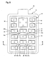
- Figs. 8 and 9 show a key sheet 26 according to the third embodiment.
- the key sheet 26 of the third embodiment differs from the key sheet 11 of the first embodiment in the construction of communicating grooves 27a of an inner frame portion 27 and connecting portions 28. That is, each bottomed communicating groove 27a formed in the hard base plate 15 leads to three through-holes 19, with the connecting portion 28 being integrally formed so as to connect them together.
- the connecting portions 28 there are formed accommodation recesses 28a for the inner light sources 5, which means that the key sheet 26 is an illumination type key sheet, in which light is guided to the operating portions 20 through the wall thickness of the connecting portions 28.
- a colorless and transparent material is used as the material as the rubber elastic material forming the connecting portions 28. More specifically, a colorless and transparent silicone rubber is used in this embodiment.
- one differing from the connecting portions 28 in refractive index is used as the material of the hard base plate 15 of this embodiment. More specifically, a white polycarbonate resin is used in this embodiment.
- the connecting portions 28 of a colorless and transparent material and the hard base plate 15 of a white material By thus forming the connecting portions 28 of a colorless and transparent material and the hard base plate 15 of a white material, the light from the inner light sources 5 is guided from the connecting portions 28 to the operating portions 20 while being reflected at the interface between the connecting portions 28 and the hard base plate 15, making it possible to brightly illuminate the keytops 12. Further, since the distance from the accommodation recesses 28a to the operating portions 20 is the same all over, it is also possible to attain uniform illumination for the keytops 12. The light entering the hard base plate 15 is diffused by the white pigment, and is not absorbed.
- the connecting portions 28 are formed of a colorless and transparent silicone rubber, which is a thermosetting elastomer.
- a thermoplastic elastomer which leaves relatively large molding marks, no large molding marks are left.
- a key sheet 29 according to the fourth embodiment is a modification of the key sheet 26 of the third embodiment.
- the key sheet 29 is formed as a small-pitch key sheet, in which the plurality of keytops 30 are collectively exposed through the operation opening 7 with no partition frame formed in the casing 2 of the electronic device 1.
- the interval between the keytops 30 is very small and ranges, for example, approximately from 0.15 mm to 0.2 mm; the distance between the keytops and the operation opening 7 is approximately as small as that.
- molding marks 28b exist in the accommodation recesses 28a of the connecting portions 28. That is, in this embodiment, the operating portions 20 and the connecting portions 28 are formed through injection molding of a thermoplastic elastomer. More specifically, a colorless and transparent styrene-based thermoplastic elastomer is used as the material. If the holding/receiving portion 18, the operating portions 20, and the connecting portions 28 are formed through injection molding of a thermoplastic elastomer, which leaves relatively large molding marks 28b, the molding marks 28b remain within the accommodation recesses 28a.
- the hard base plate 15 is formed of a black and light-blocking polypropylene resin. Thus, while a part of it is absorbed by the hard base plate 15, the light emitted from the inner light sources 5 enters the operating portions 20 through the connecting portions 28, making it possible to illuminate the keytops 30 effectively only from the back side thereof.
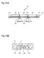
- the communicating grooves 17b, 27a are formed without allowing them to extend through the wall thickness of the inner frame portion 17, 27, it is also possible to form them as through-holes as shown in Fig. 14 . Further, while in the above-described embodiments the communicating grooves 17b, 27a are formed in the back surface of the hard base plate 15, it is also possible to form them in the front surface of the hard base plate 15, with the connecting portions 21, 28 being formed therein.
- the connecting portions 21, 28 do not protrude from the back surface of the hard base plate 15, as shown, for example, in Fig. 13
- the buffer portions 31 come into elastic contact with the printed circuit board 4, making it possible to avoid large-pressure contact of the hard base plate 15 (inner frame portion 17) and to suppress damage or deformation of the printed circuit board 4.
- the keytops 12, 30 of a rubber-like elastic material, such as a thermoplastic resin, a thermosetting resin, silicone rubber, or a thermoplastic elastomer. Further, it is possible to form on the keytops 12, 30 display portions indicating characters, figures, symbols, etc. in ink or by plating or the like. Further, the keytops 12, 30 may also be formed as open-character-illumination type keytops or character-illumination type keytops. Further, the three-dimensional configuration of the keytops 12, 30 may be other than that described above.
- the operating portions 20 are rectangular in plan view, they may also be of a circular, an elliptical, or some other polygonal configuration. Further, the configuration of the base sheet 13 and the configuration of the connecting portions 21, 28 are not restricted to those of the above-described embodiments; it is also possible to form them in some other configurations.
- key sheet 11, 25, 26, 29 of the above-described embodiments is used in the electronic device 1, it may also be formed as the key sheet of some other apparatuses, such as a PDA or a remote controller.
Landscapes
- Push-Button Switches (AREA)
- Manufacture Of Switches (AREA)
- Input From Keyboards Or The Like (AREA)
Claims (12)
- Tastenfolie (11,25,26,29), welche folgendes aufweist:eine Grundplatte (13), welche eine harte Grundplatte (15) und Bedienabschnitte aufweist, wobei die harte Grundplatte eine Vielzahl von Durchgangslöchern (19) und Bedienabschnitte (20) aufweist, die aus einem gummiartigen, elastischen Material gebildet sind, wobei das gummiartige, elastische Material an den Durchgangslöchern (19) Tastenabdeckungen (12,30) elastisch trägt und die Verschiebung der Tastenabdeckungen (12,30) unter Druck erlaubt,wobei die Tastenfolie so geformt ist, dass die oberen Flächen der Bedienabschnitte (20), welche die Tastenabdeckungen (12,30) elastisch tragen, an Positionen in Löchern gebildet sind, welche niedriger als die Oberfläche der harten Grundplatte (15) sind,dadurch gekennzeichnet , dass die harte Grundplatte (15) eine Verbindungsnut (17b,27a) aufweist, welche zu der Vielzahl von Durchgangslöchern (19) führt, und dass ein Verbindungsabschnitt (21,28), welcher die Bedienabschnitte (20) verbindet, integral in der Verbindungsnut (17b,27a) gebildet ist.
- Tastenfolie (11,25,26,29) nach Anspruch 1, wobei die Verbindungsnut (17b,27a) als ein Durchgangsloch gebildet ist, welches sich durch die harte Grundplatte (15) erstreckt und die Dicke derselben verringert.
- Tastenfolie (11,25,26,29) nach Anspruch 1 oder 2, wobei der Verbindungsabschnitt (21,28) so gebildet ist, dass er innerhalb der Dicke der harten Grundplatte (15) liegt.
- Tastenfolie (11,25,26,29) nach einem der Ansprüche 1 bis 3, wobei ein Pufferabschnitt (31), welcher von der Oberfläche der harten Grundplatte (15) hervorsteht, auf dem Verbindungabschnitt (21,28) gebildet ist.
- Tastenfolie (11,25,26,29) nach einem der Ansprüche 1 bis 4, wobei die Tastenfolie eine Gießmarke (21b,28b) auf dem Verbindungsabschnitt (21,28) aufweist.
- Tastenfolie (11,25,26,29) nach einem der Ansprüche 1 bis 5, wobei in dem Verbindungsabschnitt (21,28) ein Rücksprung (21a) gebildet ist, und wobei die Tastenfolie eine Gießmarke (21b,28b) in dem Rücksprung (21a) aufweist.
- Tastenfolie (11,25,26,29) nach einem der Ansprüche 1 bis 6, wobei die Vielzahl von Bedienabschnitten (20) und die Verbindungsabschnitte (21,28) aus einem lichtdurchlässigen gummiartigen, elastischen Material gebildet sind, und wobei Rücksprünge (17a,28a) zum Aufnehmen von inneren Lichtquellen (5), die auf dem Gerät anzuordnen sind, in den Verbindungsabschnitten (21,28) gebildet sind.
- Tastenfolie (11,25,26,29) nach einem der Ansprüche 1 bis 7, wobei das gummiartige, elastische Material farblos und transparent ist, und wobei die harte Grundplatte (15) aus einem weißen Material gebildet ist, welches sich von dem gummiartigen, elastischen Material im Brechungsindex unterscheidet.
- Tastenfolie (11,25,26,29) nach einem der Ansprüche 1 bis 8, wobei die harte Grundplatte (15) lichtdurchlässig ist.
- Tastenfolie (11,25,26,29) nach einem der Ansprüche 1 bis 9, wobei die Grundplatte (13) der Tastenfolie (11,25,26,29) mit der Vielzahl von Tastenabdeckungen (12,30) ausgestattet ist, und wobei die Tastenfolie (11,25,26,29) als eine Tastenfolie (11,25,26,29) mit geringer Teilung ausgebildet ist, bei welcher der Abstand zwischen den Tastenabdeckungen (12,30) klein ist und bei welcher die Vielzahl von Tastenabdeckungen (12,30) gemeinsam durch eine in einem elektrischen Gerät (1) gebildeten Öffnung (3) zugänglich sein kann.
- Tastenfolie (11,25,26,29) nach Anspruch 10, wobei die Tastenabdeckungen (12,30) in einem Abstand von 0,15 bis 0,2 mm angeordnet sind.
- Verfahren zur Herstellung einer Tastenfolie (11, 25,26,29), bei welchem eine harte Grundplatte, welche eine Vielzahl von Durchgangslöchern (19) aufweist, die so gebildet sind, dass sie die Grundplatte durchdringen, in einer Gießform (mold ?) (24) angeordnet wird, wobei Bedienabschnitte (20), welche die Durchgangslöcher (19) blockieren, durch Gießen eines gummiartigen, elastischen Materials gebildet werden, und wobei dann Tastenabdeckungen (12,30) an den Bedienabschnitten (20) angebracht werden, wobei das Verfahren zur Herstellung der Tastenfolie (11,25,26,29) die folgenden Schritte aufweist:Bilden der harten Grundplatte (15), welche die Vielzahl von Durchgangslöchern (19) und eine Verbindungsnut (17b,27a) aufweist, welche zu der Vielzahl von Durchgangsbohrungen (19) führt; Gießen des gummiartigen, elastischen Materials von einem Einlauf (24b) der Gießform (24), wobei der Einlauf (24b) an einer Position geöffnet ist, welche einer der Durchgangslöcher (19) oder der Verbindungsnut (17b,27a) entspricht;Bilden der Vielzahl von Bedienabschnitten (20) und eines Verbindungsabschnitts (21,28), welcher die Bedienabschnitte (20) miteinander verbindet, einteilig auf der harten Grundplatte (15);Bilden der oberen Flächen der Bedienabschnitte (20), welche die Tastenabdeckungen (12,30) elastisch tragen, an Positionen in Löchern, welche niedriger als die Oberfläche der harten Grundplatte (15) sind; undBefestigen der jeweiligen Tastenabdeckungen (12,30) an den Bedienabschnitten (20).
Priority Applications (1)
| Application Number | Priority Date | Filing Date | Title |
|---|---|---|---|
| EP08004546A EP1942513B1 (de) | 2004-07-20 | 2005-07-18 | Tastenfolie und Herstellungsverfahren für eine Tastenfolie |
Applications Claiming Priority (1)
| Application Number | Priority Date | Filing Date | Title |
|---|---|---|---|
| JP2004212111A JP4468096B2 (ja) | 2004-07-20 | 2004-07-20 | キーシート及びキーシートの製造方法 |
Related Child Applications (1)
| Application Number | Title | Priority Date | Filing Date |
|---|---|---|---|
| EP08004546A Division EP1942513B1 (de) | 2004-07-20 | 2005-07-18 | Tastenfolie und Herstellungsverfahren für eine Tastenfolie |
Publications (3)
| Publication Number | Publication Date |
|---|---|
| EP1619703A2 EP1619703A2 (de) | 2006-01-25 |
| EP1619703A3 EP1619703A3 (de) | 2006-11-29 |
| EP1619703B1 true EP1619703B1 (de) | 2008-03-19 |
Family
ID=35106736
Family Applications (2)
| Application Number | Title | Priority Date | Filing Date |
|---|---|---|---|
| EP08004546A Expired - Lifetime EP1942513B1 (de) | 2004-07-20 | 2005-07-18 | Tastenfolie und Herstellungsverfahren für eine Tastenfolie |
| EP05015521A Expired - Lifetime EP1619703B1 (de) | 2004-07-20 | 2005-07-18 | Folientastatur und Herstellungsmethode |
Family Applications Before (1)
| Application Number | Title | Priority Date | Filing Date |
|---|---|---|---|
| EP08004546A Expired - Lifetime EP1942513B1 (de) | 2004-07-20 | 2005-07-18 | Tastenfolie und Herstellungsverfahren für eine Tastenfolie |
Country Status (5)
| Country | Link |
|---|---|
| US (1) | US7655878B2 (de) |
| EP (2) | EP1942513B1 (de) |
| JP (1) | JP4468096B2 (de) |
| CN (1) | CN100550242C (de) |
| DE (2) | DE602005016618D1 (de) |
Families Citing this family (17)
| Publication number | Priority date | Publication date | Assignee | Title |
|---|---|---|---|---|
| US7465889B2 (en) * | 2005-04-28 | 2008-12-16 | Polymatech Co., Ltd. | Pushbutton switch cover sheet and method of manufacturing the same |
| JP4394047B2 (ja) * | 2005-08-05 | 2010-01-06 | 信越ポリマー株式会社 | キーフレームおよび押釦スイッチ用カバー部材 |
| JP2007213874A (ja) * | 2006-02-07 | 2007-08-23 | Sunarrow Ltd | キーベース、キーシート及びキーベース形成方法 |
| US20100009121A1 (en) * | 2006-05-15 | 2010-01-14 | Mitsubishi Plastics, Inc. | Laminated material for metal key-sheet, metal key-sheet, and metal keypad |
| USD549667S1 (en) * | 2006-05-23 | 2007-08-28 | Grand Mate Co., Ltd. | Remote controller |
| JP4668867B2 (ja) * | 2006-08-09 | 2011-04-13 | 株式会社東海理化電機製作所 | 操作装置 |
| US7978467B2 (en) * | 2007-02-05 | 2011-07-12 | Panasonic Corporation | Key sheet, press switch and electronic device provided with the press switch |
| JP4960117B2 (ja) * | 2007-02-21 | 2012-06-27 | ポリマテック株式会社 | 押釦スイッチ用加飾キーシート |
| WO2009107344A1 (ja) * | 2008-02-28 | 2009-09-03 | パナソニック株式会社 | 可動接点体とこれを用いたスイッチ |
| US8050019B2 (en) | 2008-03-18 | 2011-11-01 | Research In Motion Limited | Keypad with water and dust protection |
| DE602008004090D1 (de) | 2008-03-18 | 2011-02-03 | Research In Motion Ltd | Tastatur mit Wasser- und Staubschutz |
| CN102054610B (zh) * | 2009-10-29 | 2013-11-13 | 富士康(昆山)电脑接插件有限公司 | 按键及其制造方法 |
| WO2011080981A1 (ja) * | 2009-12-28 | 2011-07-07 | ポリマテック株式会社 | 照光式キーシート |
| US20110164910A1 (en) * | 2010-01-06 | 2011-07-07 | Shin-Etsu Polymer Co., Ltd. | Thin keypad assembly and method for manufacturing same |
| CN102832068A (zh) * | 2012-08-24 | 2012-12-19 | 鸿富锦精密工业(深圳)有限公司 | 一种按键装置及其导光膜层 |
| CN103854907B (zh) * | 2014-03-07 | 2016-03-02 | 贵阳永青仪电科技有限公司 | 一种在按键板上焊接按键的固定夹具及焊接方法 |
| CN206148326U (zh) * | 2016-08-15 | 2017-05-03 | 江海波 | 通过注塑一体成型的键盘、模具 |
Family Cites Families (11)
| Publication number | Priority date | Publication date | Assignee | Title |
|---|---|---|---|---|
| USRE29440E (en) * | 1973-01-02 | 1977-10-11 | Bowmar Instrument Corporation | Calculator keyboard switch with disc spring contact and printed circuit board |
| EP0162037B1 (de) | 1984-03-21 | 1989-04-26 | Franz Sterner | Verfahren zum Herstellen von Spritzgussteilen und Spritzgussform zur Durchführung des Verfahrens |
| JPS6318727U (de) | 1986-07-23 | 1988-02-06 | ||
| JPH078927A (ja) | 1993-06-21 | 1995-01-13 | Kao Corp | シャッター部材の超音波洗浄装置 |
| JPH078927U (ja) * | 1993-07-13 | 1995-02-07 | しなのポリマー株式会社 | 押釦スイッチ用カバー部材 |
| JPH0896653A (ja) | 1994-09-21 | 1996-04-12 | Baad Prod Kk | キーボードスイッチ用弾性材の製造方法 |
| US5661279A (en) * | 1995-10-26 | 1997-08-26 | Sunarrow Co., Ltd. | Pushbutton switch |
| JPH11144549A (ja) | 1997-11-11 | 1999-05-28 | Porimatec Kk | 硬質樹脂キートップ付キーパッドの製造方法 |
| JP2003178639A (ja) * | 2001-12-12 | 2003-06-27 | Sunarrow Ltd | ハードベース・キーユニット |
| JP4435507B2 (ja) | 2003-06-03 | 2010-03-17 | ポリマテック株式会社 | キーシート |
| WO2005093770A1 (ja) | 2004-03-25 | 2005-10-06 | Shin-Etsu Polymer Co., Ltd. | 押釦スイッチ用カバー部材とその製造方法 |
-
2004
- 2004-07-20 JP JP2004212111A patent/JP4468096B2/ja not_active Expired - Fee Related
-
2005
- 2005-07-15 US US11/181,749 patent/US7655878B2/en not_active Expired - Fee Related
- 2005-07-18 DE DE602005016618T patent/DE602005016618D1/de not_active Expired - Lifetime
- 2005-07-18 EP EP08004546A patent/EP1942513B1/de not_active Expired - Lifetime
- 2005-07-18 EP EP05015521A patent/EP1619703B1/de not_active Expired - Lifetime
- 2005-07-18 DE DE602005005395T patent/DE602005005395T2/de not_active Expired - Lifetime
- 2005-07-19 CN CNB2005100860333A patent/CN100550242C/zh not_active Expired - Fee Related
Also Published As
| Publication number | Publication date |
|---|---|
| JP4468096B2 (ja) | 2010-05-26 |
| JP2006032228A (ja) | 2006-02-02 |
| EP1942513A1 (de) | 2008-07-09 |
| CN100550242C (zh) | 2009-10-14 |
| CN1725404A (zh) | 2006-01-25 |
| US20060017693A1 (en) | 2006-01-26 |
| DE602005005395T2 (de) | 2009-04-30 |
| DE602005016618D1 (de) | 2009-10-22 |
| EP1942513B1 (de) | 2009-09-09 |
| EP1619703A2 (de) | 2006-01-25 |
| DE602005005395D1 (de) | 2008-04-30 |
| EP1619703A3 (de) | 2006-11-29 |
| US7655878B2 (en) | 2010-02-02 |
Similar Documents
| Publication | Publication Date | Title |
|---|---|---|
| EP1619703B1 (de) | Folientastatur und Herstellungsmethode | |
| JP4165646B2 (ja) | キーシート | |
| US7952043B2 (en) | Keyboard with backlighting functionality | |
| US6967292B2 (en) | Key sheet | |
| JP5301118B2 (ja) | キーアセンブリ及びこれを備えた携帯端末機 | |
| KR101283120B1 (ko) | 전자 장치용 박형 키패드 어셈블리 및 콤포넌트와 방법 | |
| CN100511530C (zh) | 用于便携式设备的具有按键支撑结构的键盘 | |
| US6861600B1 (en) | Integrated switch and backlight assembly | |
| JP4190568B1 (ja) | 携帯端末 | |
| JP4486395B2 (ja) | キーシート及びキーシートの固定構造 | |
| CN111261442A (zh) | 按键结构 | |
| US9142369B2 (en) | Stack assembly for implementing keypads on mobile computing devices | |
| WO2007135842A1 (ja) | 操作キー部品 | |
| US20110226595A1 (en) | Illumination type key sheet and push button switch | |
| US20100148994A1 (en) | Keyboard with Backlighting Functionality | |
| US6888079B2 (en) | Multifunctional pushbutton switch | |
| WO2005117047A1 (ja) | 筐体付キーユニット | |
| JP4347679B2 (ja) | キーシート | |
| KR100528493B1 (ko) | 이동 전화기의 키 패드용 키 탑 및 그 제조방법 | |
| JP5619369B2 (ja) | シートスイッチ | |
| WO2004112069A1 (ja) | キーユニット及びその製造方法 | |
| JP4430780B2 (ja) | 照光式シート状キートップおよびその製造方法 | |
| KR100880139B1 (ko) | 키 유닛과 키 유닛의 제조방법 | |
| KR100807157B1 (ko) | 포터블 전자장치들을 위한 키지지구조를 가진 키보드 | |
| KR101255010B1 (ko) | 일체형의 키버튼부를 갖는 키패드 및 이를 구비한이동단말기 |
Legal Events
| Date | Code | Title | Description |
|---|---|---|---|
| PUAI | Public reference made under article 153(3) epc to a published international application that has entered the european phase |
Free format text: ORIGINAL CODE: 0009012 |
|
| AK | Designated contracting states |
Kind code of ref document: A2 Designated state(s): AT BE BG CH CY CZ DE DK EE ES FI FR GB GR HU IE IS IT LI LT LU LV MC NL PL PT RO SE SI SK TR |
|
| AX | Request for extension of the european patent |
Extension state: AL BA HR MK YU |
|
| PUAL | Search report despatched |
Free format text: ORIGINAL CODE: 0009013 |
|
| AK | Designated contracting states |
Kind code of ref document: A3 Designated state(s): AT BE BG CH CY CZ DE DK EE ES FI FR GB GR HU IE IS IT LI LT LU LV MC NL PL PT RO SE SI SK TR |
|
| AX | Request for extension of the european patent |
Extension state: AL BA HR MK YU |
|
| RIC1 | Information provided on ipc code assigned before grant |
Ipc: H01H 13/88 20060101AFI20061025BHEP Ipc: H01H 13/704 20060101ALI20061025BHEP |
|
| 17P | Request for examination filed |
Effective date: 20070302 |
|
| 17Q | First examination report despatched |
Effective date: 20070404 |
|
| AKX | Designation fees paid |
Designated state(s): DE FI GB SE |
|
| GRAP | Despatch of communication of intention to grant a patent |
Free format text: ORIGINAL CODE: EPIDOSNIGR1 |
|
| GRAS | Grant fee paid |
Free format text: ORIGINAL CODE: EPIDOSNIGR3 |
|
| GRAA | (expected) grant |
Free format text: ORIGINAL CODE: 0009210 |
|
| AK | Designated contracting states |
Kind code of ref document: B1 Designated state(s): DE FI GB SE |
|
| REG | Reference to a national code |
Ref country code: GB Ref legal event code: FG4D |
|
| REF | Corresponds to: |
Ref document number: 602005005395 Country of ref document: DE Date of ref document: 20080430 Kind code of ref document: P |
|
| REG | Reference to a national code |
Ref country code: SE Ref legal event code: TRGR |
|
| PLBE | No opposition filed within time limit |
Free format text: ORIGINAL CODE: 0009261 |
|
| STAA | Information on the status of an ep patent application or granted ep patent |
Free format text: STATUS: NO OPPOSITION FILED WITHIN TIME LIMIT |
|
| 26N | No opposition filed |
Effective date: 20081222 |
|
| PGFP | Annual fee paid to national office [announced via postgrant information from national office to epo] |
Ref country code: FI Payment date: 20090720 Year of fee payment: 5 Ref country code: SE Payment date: 20090717 Year of fee payment: 5 |
|
| PGFP | Annual fee paid to national office [announced via postgrant information from national office to epo] |
Ref country code: GB Payment date: 20100730 Year of fee payment: 6 |
|
| PG25 | Lapsed in a contracting state [announced via postgrant information from national office to epo] |
Ref country code: FI Free format text: LAPSE BECAUSE OF NON-PAYMENT OF DUE FEES Effective date: 20100718 |
|
| PGFP | Annual fee paid to national office [announced via postgrant information from national office to epo] |
Ref country code: DE Payment date: 20110730 Year of fee payment: 7 |
|
| GBPC | Gb: european patent ceased through non-payment of renewal fee |
Effective date: 20110718 |
|
| PG25 | Lapsed in a contracting state [announced via postgrant information from national office to epo] |
Ref country code: GB Free format text: LAPSE BECAUSE OF NON-PAYMENT OF DUE FEES Effective date: 20110718 |
|
| PG25 | Lapsed in a contracting state [announced via postgrant information from national office to epo] |
Ref country code: SE Free format text: LAPSE BECAUSE OF NON-PAYMENT OF DUE FEES Effective date: 20100719 |
|
| PG25 | Lapsed in a contracting state [announced via postgrant information from national office to epo] |
Ref country code: DE Free format text: LAPSE BECAUSE OF NON-PAYMENT OF DUE FEES Effective date: 20130201 |
|
| REG | Reference to a national code |
Ref country code: DE Ref legal event code: R119 Ref document number: 602005005395 Country of ref document: DE Effective date: 20130201 |