EP1619443A2 - Oven with controllable ventilation - Google Patents
Oven with controllable ventilation Download PDFInfo
- Publication number
- EP1619443A2 EP1619443A2 EP05015520A EP05015520A EP1619443A2 EP 1619443 A2 EP1619443 A2 EP 1619443A2 EP 05015520 A EP05015520 A EP 05015520A EP 05015520 A EP05015520 A EP 05015520A EP 1619443 A2 EP1619443 A2 EP 1619443A2
- Authority
- EP
- European Patent Office
- Prior art keywords
- opening
- cooking
- appliance according
- cooking appliance
- sensor
- Prior art date
- Legal status (The legal status is an assumption and is not a legal conclusion. Google has not performed a legal analysis and makes no representation as to the accuracy of the status listed.)
- Granted
Links
- 238000009423 ventilation Methods 0.000 title 1
- 238000010411 cooking Methods 0.000 claims abstract description 69
- 230000001681 protective effect Effects 0.000 claims description 9
- 238000001514 detection method Methods 0.000 claims description 2
- 238000001816 cooling Methods 0.000 claims 1
- 238000010438 heat treatment Methods 0.000 claims 1
- 239000003517 fume Substances 0.000 description 2
- 206010053648 Vascular occlusion Diseases 0.000 description 1
- 238000013459 approach Methods 0.000 description 1
- 230000007423 decrease Effects 0.000 description 1
- 230000001419 dependent effect Effects 0.000 description 1
- 238000005265 energy consumption Methods 0.000 description 1
- 230000000630 rising effect Effects 0.000 description 1
Images
Classifications
-
- F—MECHANICAL ENGINEERING; LIGHTING; HEATING; WEAPONS; BLASTING
- F24—HEATING; RANGES; VENTILATING
- F24C—DOMESTIC STOVES OR RANGES ; DETAILS OF DOMESTIC STOVES OR RANGES, OF GENERAL APPLICATION
- F24C15/00—Details
- F24C15/20—Removing cooking fumes
- F24C15/2007—Removing cooking fumes from oven cavities
Definitions
- the invention relates to a cooking appliance according to the preamble of claim 1.
- the cooking chamber has two openings. At a first of these openings is a sensor for detecting escaping vapor. The second opening is arranged at a fan. If the sensor exiting vapors detected, the fan is turned on or operated amplified so that the exiting through the second opening fumes is conveyed away. It is also proposed to arrange a controllable slide at the second opening.
- the object is to reduce the energy consumption of this device.
- the cooking appliance is thus designed such that the fan generates an overpressure in the downstream pressure chamber.
- the first opening opens into this pressure chamber. This leads to the fact that the vapors on exiting through the first opening must overcome the pressure prevailing in the pressure chamber overpressure.
- the sensor detects a Wrasenaustritt only at the first opening when there is a certain overpressure in the cooking chamber. This is why the sensor only responds when excessive steam is actually generated in the cooking chamber. It can be seen that the energy loss can be reduced by this measure without the moisture in the cooking chamber rising inadmissibly.
- the second opening opens into the suction area of the blower, so that the fumes are efficiently conveyed away when the closure is opened.
- the cooking appliance according to FIG. 1 has a cooking chamber 1, which is delimited by walls 2 and a door 3.
- the cooking appliance shown as an example can be operated both as an oven and as a steam cooker. Accordingly, it has, in addition to conventional resistive heaters (not shown), a steam generator 4, as e.g. in EP 1 166 694.
- a cross-flow fan 6 is arranged as a fan. This promotes air from a suction 7 in a pressure chamber 8. From the pressure chamber 8, the pumped air passes through a front outlet opening 9 of the device in the environment.
- the pressure chamber 9 is bounded above by an inclined cover plate 10 and down through an inclined bottom plate 11, such that the pressure chamber 8 tapers towards the outlet opening 9. Laterally, the pressure chamber is closed by side walls (not shown).
- two openings are arranged, which are approximately equal in size and, for. each have a diameter of about 2.5 cm.
- a first opening 14 leads from the cooking chamber 1 in the interior 15 of a protective housing 16.
- the protective housing 16 is arranged in the pressure chamber 8 and communicates with this via a connection opening 17.
- the connection opening 17 is located on the side facing away from the fan of the protective housing 16.
- a temperature sensor 18 is further arranged at the mouth of the first opening 14.
- the first opening 14 is always open.
- a second opening 20 connects the cooking chamber 1 with the suction area 7 in front of the blower 6.
- a closure 21 is provided, which consists of a flap 22 which can be pushed by a stepping or servomotor 23 more or less over the mouth of the opening 20, such that the closure substantially continuously from a closed in an open position can be transferred.
- a controller 24 is provided, which among other things monitors the temperature signal output by the temperature sensor 18.
- the fan G is constantly in operation. It sucks in air through openings in the rear wall and in the side walls of the cooking appliance from the environment. This air passes through the suction region 7, is blown into the pressure chamber 8 and leaves it through the outlet opening 9. Since the pressure chamber 8 is tapered towards the outlet opening 9, a slight overpressure arises in the pressure chamber 8.
- blower 6 it is an object of the blower 6 is to dissipate to cool the device air, which has warmed on the outside of the cooking chamber to the outside.
- the function of the cooking appliance depends on whether it is used as a steam cooker or as a conventional thermal oven.
- the food or the cooking chamber 1 is heated by the resistive heaters, not shown.
- the cooking chamber temperature Tgr above 100 ° C increase.
- the shutter 21 is in the closed position because the controller 24 is configured to maintain the temperature at the temperature sensor 18 at a predetermined value Tr of, for example, 63 ° C ,
- the controller 24 starts to open the second opening 20 by operating the stepping motor 23.
- the cooking chamber 1 is connected via the second opening 20 with the suction region 7, where a relatively low pressure prevails, so that the vapor is discharged through the opening 20 and the pressure in the cooking chamber 1 is discharged.
- the pressure gradient between the pressure chamber 8 and cooking chamber 1 is reversed, and it occurs only cooler and drier air from the pressure chamber 8 in the oven, causing the temperature sensor 8 cools, so that the controller 24 closes the shutter 21 again.
- the controller 24 thus forms a control loop which tries to keep the temperature Ts at the sensor 18 approximately at the value Tr by opening the shutter 21 more or less strongly.
- the controller 24 preferably completely closes the closure 21, so that no further vapor can escape and an unnecessary loss of energy is avoided.
- vapor is removed as required from the cooking chamber 1.
- the fan 6 can remain permanently in operation, independently of the temperature value Ts of the sensor, and thus cool the cooking appliance.
- a separate fan for extracting excess vapor from the cooking chamber 1 is not required, a cross-flow fan is sufficient.
- the shutter 21 In operation as Dampfgar Eat the shutter 21 is normally closed. However, the controller again monitors the temperature Ts at the sensor 18 and uses it to control the power of the steam generator 4 in the manner described in EP 1 166 694.
- the closure 21 can be opened at the end of the steam-cooking operation and thus the steam can be discharged from the cooking chamber 1. At the same time drier air is introduced via the first opening 14 in the cooking chamber 1.
- the opening 14 and the temperature sensor 18 can be used in both modes for device control.
- the protective housing 16 shields the temperature sensor 18 from the air coming from the fan 6, so that the temperature sensor 18 can detect even small amounts of leaking vapor or vapor.
- the cooking chamber 1 When the door 3 is closed, the cooking chamber 1 is gastight except for the first and the second opening. In steam cooking operation is thus prevented that uncontrolled escape of steam from the oven and, for. Can cause moisture damage. In conventional furnace operation, the air exchange with the environment occurs in a controlled manner via the openings 14 and 20.
- the temperature Tr can be a fixed, predetermined value. However, it can also be selected depending on the temperature in the cooking chamber 1. It can thus be taken into account that the vapor emerging from the hot cooking chamber has a higher temperature, which allows a more accurate detection of Wrasens and thus a better control of the device.
- the closure 21 can be kept partially open or completely open, at least in one program phase, independently of the temperature at the sensor 18.
- the cooking appliance can be configured such that, when a selection is made special program, while at least a portion of the program keeps the shutter 21 at least partially independent of the sensor 18.
- a sensor for detecting the vapor emerging through the first opening 14 another suitable sensor may also be used instead of a temperature sensor, as described in EP 1 156 282.
Abstract
Description
Die Erfindung betrifft ein Gargerät gemäss Oberbegriff von Anspruch 1.The invention relates to a cooking appliance according to the preamble of
Aus EP 1 156 282 ist ein Backofen bekannt, dessen Garraum zwei Öffnungen aufweist. Bei einer ersten dieser Öffnungen befindet sich ein Sensor zur Detektion von austretendem Wrasen. Die zweite Öffnung ist bei einem Ventilator angeordnet. Wird vom Sensor austretender Wrasen detektiert, so wird der Ventilator eingeschaltet oder verstärkt betrieben, damit der durch die zweite Öffnung austretenden Wrasen weggefördert wird. Es wird auch vorgeschlagen, an der zweiten Öffnung einen steuerbaren Schieber anzuordnen.From
Es stellt sich die Aufgabe, den Energieverbrauch dieser Vorrichtung zu reduzieren.The object is to reduce the energy consumption of this device.
Diese Aufgabe wird durch das Gargerät gemäss Anspruch 1 gelöst.This object is achieved by the cooking appliance according to
Anspruchsgemäss ist das Gargerät also so ausgestaltet, dass das Gebläse im nachgeschalteten Druckraum einen Überdruck erzeugt. Die erste Öffnung mündet in diesen Druckraum. Dies führt dazu, dass der Wrasen beim Austritt durch die erste Öffnung den im Druckraum herrschenden Überdruck überwinden muss. Somit detektiert der Sensor bei der ersten Öffnung erst dann einen Wrasenaustritt, wenn ein gewisser Überdruck im Garraum herrscht. Deshalb spricht der Sensor nur dann an, wenn tatsächlich übermässig viel Dampf im Garraum erzeugt wird. Es zeigt sich, dass durch diese Massnahme der Energieverlust reduziert werden kann, ohne dass die Feuchte im Garraum unzulässig ansteigt.According to the claim, the cooking appliance is thus designed such that the fan generates an overpressure in the downstream pressure chamber. The first opening opens into this pressure chamber. This leads to the fact that the vapors on exiting through the first opening must overcome the pressure prevailing in the pressure chamber overpressure. Thus, the sensor detects a Wrasenaustritt only at the first opening when there is a certain overpressure in the cooking chamber. This is why the sensor only responds when excessive steam is actually generated in the cooking chamber. It can be seen that the energy loss can be reduced by this measure without the moisture in the cooking chamber rising inadmissibly.
Vorzugsweise mündet die zweite Öffnung in den Ansaugbereich des Gebläses, so dass beim Öffnen des Verschlusses der Wrasen effizient weggefördert wird.Preferably, the second opening opens into the suction area of the blower, so that the fumes are efficiently conveyed away when the closure is opened.
Weitere bevorzugte Ausführungen ergeben sich aus den abhängigen Ansprüchen sowie aus der nun folgenden Beschreibung anhand der Figuren. Dabei zeigen:
- Fig. 1 eine schematische Ansicht der wichtigsten Komponenten eines Gargeräts und
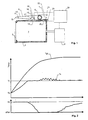
- Fig. 2 ein Beispiel möglicher Temperaturverläufe im Garraum und beim Temperatursensor (obere Grafik) und der Stellung des Verschlusses der zweiten Öffnung (untere Grafik).
- Fig. 1 is a schematic view of the main components of a cooking appliance and
- 2 shows an example of possible temperature profiles in the cooking chamber and the temperature sensor (upper graph) and the position of the closure of the second opening (lower graph).
Das Gargerät gemäss Fig. 1 besitzt einen Garraum 1, der von Wänden 2 und einer Türe 3 begrenzt wird. Das als Beispiel gezeigte Gargerät kann sowohl als Backofen, als auch als Dampfgargerät betrieben werden. Entsprechend besitzt es nebst konventioneller resistiver Heizungen (nicht gezeigt) einen Dampfgenerator 4, wie er z.B. in EP 1 166 694 beschreiben ist.The cooking appliance according to FIG. 1 has a
Ausserhalb des Garraums 1 ist ein Querstromlüfter 6 als Gebläse angeordnet. Dieser fördert Luft von einem Ansaugbereich 7 in einen Druckraum 8. Vom Druckraum 8 tritt die geförderte Luft durch eine frontseitige Austrittsöffnung 9 des Geräts in die Umgebung aus. Der Druckraum 9 wird nach oben durch eine geneigte Deckplatte 10 und nach unten durch eine geneigte Bodenplatte 11 begrenzt, derart, dass sich der Druckraum 8 gegen die Austrittsöffnung 9 hin verjüngt. Seitlich ist der Druckraum durch Seitenwände (nicht gezeigt) geschlossen.Outside the
In der Decke des Garraums 1 sind zwei Öffnungen angeordnet, die ungefähr gleich gross sind und z.B. je einen Durchmesser von ca. 2.5 cm besitzen.In the ceiling of the
Eine erste Öffnung 14 führt vom Garraum 1 in den Innenraum 15 eines Schutzgehäuses 16. Das Schutzgehäuse 16 ist im Druckraum 8 angeordnet und kommuniziert mit diesem über eine Verbindungsöffnung 17. Die Verbindungsöffnung 17 befindet sich auf der dem Gebläse abgewandten Seite des Schutzgehäuses 16. Im Schutzgehäuse 16 ist ferner bei der Mündung der ersten Öffnung 14 ein Temperatursensor 18 angeordnet. Die erste Öffnung 14 ist immer geöffnet.A
Eine zweite Öffnung 20 verbindet den Garraum 1 mit dem Ansaugbereich 7 vor dem Gebläse 6. Zum Verschliessen der zweiten Öffnung 20 ist ein Verschluss 21 vorgesehen, der aus einer Klappe 22 besteht, die von einem Schritt- oder Servomotor 23 mehr oder weniger weit über die Mündung der Öffnung 20 geschoben werden kann, derart dass der Verschluss im wesentlichen kontinuierlich von einer geschlossenen in eine geöffnete Stellung übergeführt werden kann.A
Zur Steuerung des Dampfgenerators 4, des Verschlusses 21 und der weiteren Komponenten des Gargeräts ist eine Steuerung 24 vorgesehen, die unter anderem das vom Temperatursensor 18 abgegebene Temperatursignal überwacht.For controlling the steam generator 4, the
Im Betrieb des Gargeräts ist das Gebläse G dauernd im Betrieb. Dabei saugt es Luft durch Öffnungen in der Rückwand und in den Seitenwänden des Gargeräts aus der Umgebung an. Diese Luft durchtritt den Ansaugbereich 7, wird in den Druckraum 8 geblasen und verlässt diesen durch die Austrittsöffnung 9. Da der Druckraum 8 gegen die Austrittsöffnung 9 hin verjüngt ist, entsteht dabei im Druckraum 8 ein leichter Überdruck.During operation of the cooking appliance, the fan G is constantly in operation. It sucks in air through openings in the rear wall and in the side walls of the cooking appliance from the environment. This air passes through the
Somit besteht eine Aufgabe des Gebläses 6 darin, zur Kühlung des Geräts Luft, die sich an der Aussenseite des Garraums erwärmt hat, nach aussen abzuführen.Thus, it is an object of the
Die Funktion des Gargeräts hängt davon ab, ob es als Dampfgargerät oder als konventioneller thermischer Backofen verwendet wird.The function of the cooking appliance depends on whether it is used as a steam cooker or as a conventional thermal oven.
Im konventionellen Betrieb wird das Gargut bzw. der Garraum 1 über die nicht gezeigten resistiven Heizungen erwärmt. Dabei kann, wie in Fig. 2 dargestellt, die Garraumtemperatur Tgr über 100 °C ansteigen.In conventional operation, the food or the
Zu Beginn einer konventionellen Garphase, wie sie in Fig. 2 illustriert wird, befindet sich der Verschluss 21 in der geschlossenen Stellung, da die Steuerung 24 dazu ausgestaltet ist, die Temperatur beim Temperatursensor 18 auf einem vorgegebenen Wert Tr von z.B. 63 °C zu halten.At the beginning of a conventional cooking phase, as illustrated in FIG. 2, the
Steigt die Temperatur Tgr des Garraums über 100 °C, kommt es zu einem mehr oder weniger starken Dampfaustritt aus dem Gargut. Dadurch steigt der Druck im Garraum 1 an. Übersteigt dieser Druck den Druck im Druckraum 8, so tritt der Wrasen durch die erste Öffnung 14 in den Innenraum 15 des Schutzgehäuses 16 und somit in den Druckraum 8. Dabei streicht sie am Temperatursensor 18 vorbei, so dass die von ihm gemessene Temperatur Ts ansteigt.If the temperature Tgr of the cooking chamber rises above 100 ° C, there will be a more or less strong escape of steam from the food. As a result, the pressure in the
Nähert sich die Temperatur Ts dem Wert Tr oder übersteigt sie diesen, so beginnt die Steuerung 24, die zweite Öffnung 20 zu öffnen, indem sie den Schrittmotor 23 betätigt. Damit wird der Garraum 1 über die zweite Öffnung 20 mit dem Ansaugbereich 7 verbunden, wo ein relativ geringer Druck herrscht, so dass der Wrasen durch die Öffnung 20 abgeführt und der Überdruck im Garraum 1 entladen wird. Damit kehrt sich das Druckgefälle zwischen Druckraum 8 und Garraum 1 um, und es tritt nur kühlere und trockenere Luft aus dem Druckraum 8 in den Garraum, wodurch sich der Temperatursensor 8 abkühlt, so dass die Steuerung 24 den Verschluss 21 wieder schliesst.When the temperature Ts approaches or exceeds the value Tr, the
Somit bildet die Steuerung 24 also einen Regelkreis, der versucht, durch mehr oder weniger starkes Öffnen des Verschlusses 21 die Temperatur Ts am Sensor 18 ungefähr auf dem Wert Tr zu halten.Thus, the
Übersteigt die Dampferzeugungsrate im Garraum 1 einen gewissen Wert, z.B. beim Garen eines relativ grossen, feuchten Garguts, so bleibt (wie in Fig. 2 dargestellt) der Verschluss 21 ganz geöffnet und die Temperatur Ts am Sensor 18 übersteigt den Wert Tr deutlich, bis die Dampferzeugungsrate wieder zurückgeht.If the steam generation rate in the
Bleibt die Temperatur am Temperatursensor 18 tief und wird somit kein Wrasenaustritt mehr beobachtet, so schliesst die Steuerung 24 den Verschluss 21 vorzugsweise ganz, so dass nicht weiter Wrasen austreten kann und ein unnötiger Energieverlust vermieden wird.If the temperature at the
Auf diese Weise wird bedarfsgerecht Wrasen aus dem Garraum 1 abgeführt. Gleichzeitig kann aber das Gebläse 6 dauernd und unabhängig vom Temperaturwert Ts des Sensors im Betrieb bleiben und somit das Gargerät kühlen. Ein separates Gebläse zum Absaugen von überschüssigem Wrasen aus dem Garraum 1 ist nicht erforderlich, ein Querstromlüfter genügt.In this way, vapor is removed as required from the
Im Betrieb als Dampfgargerät bleibt der Verschluss 21 normalerweise geschlossen. Die Steuerung überwacht aber wiederum die Temperatur Ts beim Sensor 18 und verwendet sie, um in der in EP 1 166 694 beschriebenen Weise die Leistung des Dampfgenerators 4 zu steuern.In operation as Dampfgargerät the
Optional kann am Ende des Dampfgarbetriebs der Verschluss 21 geöffnet und so der Dampf aus dem Garraum 1 abgeleitet werden. Gleichzeitig wird trockenere Luft über die erste Öffnung 14 in den Garraum 1 eingeleitet.Optionally, the
Somit können die Öffnung 14 und der Temperatursensor 18 in beiden Betriebsarten zur Gerätesteuerung verwendet werden.Thus, the
Dabei schirmt das Schutzgehäuse 16 den Temperatursensor 18 von der vom Gebläse 6 kommenden Luft ab, so dass der Temperatursensor 18 schon kleine Mengen von austretendem Wrasen bzw. Dampf detektieren kann.In this case, the
Bei geschlossener Türe 3 ist der Garraum 1 bis auf die erste und die zweite Öffnung gasdicht. Im Dampfgarbetrieb wird damit verhindert, dass Dampf unkontrolliert aus dem Garraum entweichen und z.B. Feuchtigkeitsschäden verursachen kann. Im konventionellen Ofenbetrieb erfolgt der Luftaustausch mit der Umgebung in kontrollierter Weise über die Öffnungen 14 und 20.When the
Wie erwähnt, kann die Temperatur Tr ein fester, vorgegebener Wert sein. Sie kann jedoch auch abhängig von der Temperatur im Garraum 1 gewählt werden. Damit kann berücksichtigt werden, dass der aus dem heissen Garraum austretende Wrasen eine höhere Temperatur besitzt, was eine genauere Detektion des Wrasens und somit eine bessere Regelung des Geräts erlaubt.As mentioned, the temperature Tr can be a fixed, predetermined value. However, it can also be selected depending on the temperature in the
Je nach Gargut kann es auch sinnvoll sein, den Verschluss 21 unabhängig vom Signal des Sensors 18 zu steuern. Beispielsweise kann bei Produkten, welchen sehr viel Feuchte zu entziehen ist, der Verschluss 21 zumindest in einer Programmphase dauernd teilweise oder ganz offen gehalten werden, unabhängig von der Temperatur am Sensor 18. Hierzu kann das Gargerät so ausgestaltet werden, dass es, bei Anwahl eines speziellen Garprogramms, während mindestens eines Teils des Programms den Verschluss 21 unabhängig vom Sensor 18 mindestens teilweise offen hält.Depending on the food to be cooked, it may also be useful to control the
Als Sensor zur Detektion des durch die erste Öffnung 14 austretenden Wrasens kann anstelle eines Temperatursensors auch ein anderer geeigneter Sensor verwendet werden, wie dies in EP 1 156 282 beschrieben ist.As a sensor for detecting the vapor emerging through the
Claims (15)
einem Garraum (1),
einem Gebläse (6) zum Fördern von Gas aus einem Ansaugbereich (7) ausserhalb des Garraums (1) in einen Druckraum (8) ausserhalb des Garraums (1),
einer ersten Öffnung (14) im Garraum (1),
einem Sensor (18) zum Detektieren von durch die erste Öffnung (14) austretendem Wrasen,
einer zweiten Öffnung (20) im Garraum (1), welche beabstandet von der ersten Öffnung (14) angeordnet ist und
einem Verschluss (21) zum Verschliessen der zweiten Öffnung (20) und einer Verschlusssteuerung (24) zur Steuerung des Verschlusses (21) abhängig von einem Signal des Sensors (18),
dadurch gekennzeichnet, dass das Gebläse (6) zum Erzeugen eines Überdrucks im Druckraum (8) ausgestaltet ist und dass die erste Öffnung (14) in den Druckraum (8) mündet.Cooking appliance with
a cooking chamber (1),
a blower (6) for conveying gas from an intake region (7) outside the cooking chamber (1) into a pressure chamber (8) outside the cooking chamber (1),
a first opening (14) in the cooking chamber (1),
a sensor (18) for detecting vapor escaping through the first opening (14),
a second opening (20) in the cooking chamber (1), which is arranged at a distance from the first opening (14) and
a closure (21) for closing the second opening (20) and a closure control (24) for controlling the closure (21) in response to a signal from the sensor (18),
characterized in that the blower (6) for generating an overpressure in the pressure chamber (8) is configured and that the first opening (14) opens into the pressure chamber (8).
Priority Applications (2)
| Application Number | Priority Date | Filing Date | Title |
|---|---|---|---|
| PL05015520T PL1619443T3 (en) | 2004-07-21 | 2005-07-18 | Oven with controllable ventilation |
| SI200531978T SI1619443T1 (en) | 2004-07-21 | 2005-07-18 | Oven with controllable ventilation |
Applications Claiming Priority (1)
| Application Number | Priority Date | Filing Date | Title |
|---|---|---|---|
| CH01235/04A CH711637B1 (en) | 2004-07-21 | 2004-07-21 | Cooking appliance with controllable ventilation. |
Publications (3)
| Publication Number | Publication Date |
|---|---|
| EP1619443A2 true EP1619443A2 (en) | 2006-01-25 |
| EP1619443A3 EP1619443A3 (en) | 2008-04-16 |
| EP1619443B1 EP1619443B1 (en) | 2015-04-08 |
Family
ID=35134116
Family Applications (1)
| Application Number | Title | Priority Date | Filing Date |
|---|---|---|---|
| EP05015520.9A Active EP1619443B1 (en) | 2004-07-21 | 2005-07-18 | Oven with controllable ventilation |
Country Status (5)
| Country | Link |
|---|---|
| EP (1) | EP1619443B1 (en) |
| CH (1) | CH711637B1 (en) |
| DK (1) | DK1619443T3 (en) |
| PL (1) | PL1619443T3 (en) |
| SI (1) | SI1619443T1 (en) |
Cited By (9)
| Publication number | Priority date | Publication date | Assignee | Title |
|---|---|---|---|---|
| EP1847203A1 (en) | 2007-06-26 | 2007-10-24 | V-Zug AG | Refining preparation with vapour escape detection |
| EP1855058A1 (en) * | 2006-08-24 | 2007-11-14 | V-Zug AG | Process and apparatus to cook dishes with vapour |
| EP2154435A2 (en) | 2008-08-06 | 2010-02-17 | Rational AG | Cooking device and method for monitoring a cooking process |
| WO2011080097A3 (en) * | 2009-12-31 | 2011-09-29 | Arcelik Anonim Sirketi | Oven with a ventilating device |
| EP3438552A4 (en) * | 2016-06-03 | 2019-05-08 | Samsung Electronics Co., Ltd. | Oven |
| EP3770508A2 (en) | 2020-11-27 | 2021-01-27 | V-Zug AG | Cooking method for operating a cooking device and cooking device |
| CN112656245A (en) * | 2020-12-31 | 2021-04-16 | 广东美的厨房电器制造有限公司 | Cooking appliance, control method of cooking appliance, and readable storage medium |
| CN115005692A (en) * | 2022-06-30 | 2022-09-06 | 杭州老板电器股份有限公司 | Cooking appliance and control method thereof |
| DE102022200778A1 (en) | 2022-01-25 | 2023-07-27 | BSH Hausgeräte GmbH | Device for discharging a stream of vapor and oven or cooking appliance |
Citations (2)
| Publication number | Priority date | Publication date | Assignee | Title |
|---|---|---|---|---|
| EP0319673A1 (en) | 1987-12-11 | 1989-06-14 | Electrolux-Juno Küchentechnik GmbH | Device and method for controlling the steam in a steam-proofing apparatus |
| EP1156282A1 (en) | 2000-05-17 | 2001-11-21 | V-Zug AG | Cooking oven with venting system |
Family Cites Families (2)
| Publication number | Priority date | Publication date | Assignee | Title |
|---|---|---|---|---|
| DE3209541A1 (en) * | 1982-03-16 | 1983-09-29 | Bosch-Siemens Hausgeräte GmbH, 7000 Stuttgart | Baking oven |
| DE10019934A1 (en) * | 2000-04-20 | 2001-10-31 | We Ma Werkzeug Und Maschb Gmbh | Device for a heating oven provided with an oven door |
-
2004
- 2004-07-21 CH CH01235/04A patent/CH711637B1/en unknown
-
2005
- 2005-07-18 PL PL05015520T patent/PL1619443T3/en unknown
- 2005-07-18 SI SI200531978T patent/SI1619443T1/en unknown
- 2005-07-18 EP EP05015520.9A patent/EP1619443B1/en active Active
- 2005-07-18 DK DK05015520.9T patent/DK1619443T3/en active
Patent Citations (2)
| Publication number | Priority date | Publication date | Assignee | Title |
|---|---|---|---|---|
| EP0319673A1 (en) | 1987-12-11 | 1989-06-14 | Electrolux-Juno Küchentechnik GmbH | Device and method for controlling the steam in a steam-proofing apparatus |
| EP1156282A1 (en) | 2000-05-17 | 2001-11-21 | V-Zug AG | Cooking oven with venting system |
Cited By (17)
| Publication number | Priority date | Publication date | Assignee | Title |
|---|---|---|---|---|
| EP1855058A1 (en) * | 2006-08-24 | 2007-11-14 | V-Zug AG | Process and apparatus to cook dishes with vapour |
| EP2189084A1 (en) * | 2007-06-26 | 2010-05-26 | V-Zug AG | Refining preparation with vapour escape detection |
| EP2279682A1 (en) | 2007-06-26 | 2011-02-02 | V-Zug AG | Preparation of food products by cooking with vapour escape detection |
| EP1847203A1 (en) | 2007-06-26 | 2007-10-24 | V-Zug AG | Refining preparation with vapour escape detection |
| EP2154435A2 (en) | 2008-08-06 | 2010-02-17 | Rational AG | Cooking device and method for monitoring a cooking process |
| EP2154435A3 (en) * | 2008-08-06 | 2010-12-08 | Rational AG | Cooking device and method for monitoring a cooking process |
| WO2011080097A3 (en) * | 2009-12-31 | 2011-09-29 | Arcelik Anonim Sirketi | Oven with a ventilating device |
| US11067287B2 (en) | 2016-06-03 | 2021-07-20 | Samsung Electronics Co., Ltd. | Oven |
| EP3438552A4 (en) * | 2016-06-03 | 2019-05-08 | Samsung Electronics Co., Ltd. | Oven |
| EP3770508A2 (en) | 2020-11-27 | 2021-01-27 | V-Zug AG | Cooking method for operating a cooking device and cooking device |
| EP3770508A3 (en) * | 2020-11-27 | 2021-06-23 | V-Zug AG | Cooking method for operating a cooking device and cooking device |
| US20220167646A1 (en) * | 2020-11-27 | 2022-06-02 | V-Zug Ag | Cooking method for operating a cooking device |
| CN112656245A (en) * | 2020-12-31 | 2021-04-16 | 广东美的厨房电器制造有限公司 | Cooking appliance, control method of cooking appliance, and readable storage medium |
| CN112656245B (en) * | 2020-12-31 | 2023-11-17 | 广东美的厨房电器制造有限公司 | Cooking appliance, control method of cooking appliance, and readable storage medium |
| DE102022200778A1 (en) | 2022-01-25 | 2023-07-27 | BSH Hausgeräte GmbH | Device for discharging a stream of vapor and oven or cooking appliance |
| WO2023143931A1 (en) | 2022-01-25 | 2023-08-03 | BSH Hausgeräte GmbH | Device for discharging a vapour flow and oven or cooking appliance |
| CN115005692A (en) * | 2022-06-30 | 2022-09-06 | 杭州老板电器股份有限公司 | Cooking appliance and control method thereof |
Also Published As
| Publication number | Publication date |
|---|---|
| PL1619443T3 (en) | 2015-08-31 |
| CH711637B1 (en) | 2017-04-13 |
| EP1619443A3 (en) | 2008-04-16 |
| DK1619443T3 (en) | 2015-05-26 |
| SI1619443T1 (en) | 2015-08-31 |
| EP1619443B1 (en) | 2015-04-08 |
Similar Documents
| Publication | Publication Date | Title |
|---|---|---|
| EP1619443B1 (en) | Oven with controllable ventilation | |
| EP2466211B1 (en) | Method for operating a cooking device | |
| EP2279682B1 (en) | Preparation of food products by cooking with vapour escape detection | |
| EP3470739A1 (en) | Cooking device and method for carrying out a processing process | |
| EP2775215B1 (en) | Baking oven with temperature limitation depending on the climate in the oven | |
| EP1855058B1 (en) | Process and apparatus to cook dishes with vapour | |
| EP1906096A2 (en) | Method for regulating the exhaust air volume flow from the cooking chamber of an oven | |
| DE102016215650A1 (en) | Haushaltsgargerät | |
| EP2848868A1 (en) | Baking oven with humidity sensor and air management system | |
| EP2662630B1 (en) | Method for preparing a cooked good and cooking device | |
| DE19955820A1 (en) | Leavening chamber that can be sealed to provide anaerobic leavening under strictly controlled conditions. | |
| DE69919268T2 (en) | Oven with hot air circulation | |
| EP1816402A2 (en) | Oven | |
| EP2445311B1 (en) | Combination cooking device | |
| DE60116849T2 (en) | Steam outlet for steam cooking appliances | |
| EP3807576B1 (en) | Cooking device | |
| EP0845234B2 (en) | Device and method to control the amount of humidity in a cooking device | |
| EP2468101B1 (en) | Method for operating a cooking device and a cooking device | |
| EP2220970B2 (en) | Refining preparation with detection of a cooling rate | |
| EP2662631A1 (en) | Method for cooking a cooked good and cooking device | |
| EP3399245A2 (en) | Cooking device | |
| DE10211522A1 (en) | Oven, especially with a mechanism for pyrolytic self-cleaning comprises a controllable flap for controlling the airflow into oven | |
| DE102010061353A1 (en) | Cooking appliance and method for operating a cooking appliance | |
| BE1029396B1 (en) | Process for cooling the vapor or steam escaping from the cooking chamber of a cooking appliance and cooking appliance | |
| CH696039A5 (en) | Combined oven with microwave and drying function. |
Legal Events
| Date | Code | Title | Description |
|---|---|---|---|
| PUAI | Public reference made under article 153(3) epc to a published international application that has entered the european phase |
Free format text: ORIGINAL CODE: 0009012 |
|
| AK | Designated contracting states |
Kind code of ref document: A2 Designated state(s): AT BE BG CH CY CZ DE DK EE ES FI FR GB GR HU IE IS IT LI LT LU LV MC NL PL PT RO SE SI SK TR |
|
| AX | Request for extension of the european patent |
Extension state: AL BA HR MK YU |
|
| PUAL | Search report despatched |
Free format text: ORIGINAL CODE: 0009013 |
|
| AK | Designated contracting states |
Kind code of ref document: A3 Designated state(s): AT BE BG CH CY CZ DE DK EE ES FI FR GB GR HU IE IS IT LI LT LU LV MC NL PL PT RO SE SI SK TR |
|
| AX | Request for extension of the european patent |
Extension state: AL BA HR MK YU |
|
| 17P | Request for examination filed |
Effective date: 20081014 |
|
| AKX | Designation fees paid |
Designated state(s): AT BE BG CH CY CZ DE DK EE ES FI FR GB GR HU IE IS IT LI LT LU LV MC NL PL PT RO SE SI SK TR |
|
| GRAP | Despatch of communication of intention to grant a patent |
Free format text: ORIGINAL CODE: EPIDOSNIGR1 |
|
| INTG | Intention to grant announced |
Effective date: 20141117 |
|
| GRAS | Grant fee paid |
Free format text: ORIGINAL CODE: EPIDOSNIGR3 |
|
| GRAA | (expected) grant |
Free format text: ORIGINAL CODE: 0009210 |
|
| AK | Designated contracting states |
Kind code of ref document: B1 Designated state(s): AT BE BG CH CY CZ DE DK EE ES FI FR GB GR HU IE IS IT LI LT LU LV MC NL PL PT RO SE SI SK TR |
|
| REG | Reference to a national code |
Ref country code: GB Ref legal event code: FG4D Free format text: NOT ENGLISH |
|
| REG | Reference to a national code |
Ref country code: CH Ref legal event code: NV Representative=s name: E. BLUM AND CO. AG PATENT- UND MARKENANWAELTE , CH Ref country code: CH Ref legal event code: EP |
|
| REG | Reference to a national code |
Ref country code: IE Ref legal event code: FG4D Free format text: LANGUAGE OF EP DOCUMENT: GERMAN |
|
| REG | Reference to a national code |
Ref country code: AT Ref legal event code: REF Ref document number: 720883 Country of ref document: AT Kind code of ref document: T Effective date: 20150515 |
|
| REG | Reference to a national code |
Ref country code: DE Ref legal event code: R096 Ref document number: 502005014745 Country of ref document: DE Effective date: 20150521 |
|
| REG | Reference to a national code |
Ref country code: DK Ref legal event code: T3 Effective date: 20150521 |
|
| REG | Reference to a national code |
Ref country code: SE Ref legal event code: TRGR |
|
| REG | Reference to a national code |
Ref country code: NL Ref legal event code: T3 |
|
| REG | Reference to a national code |
Ref country code: NL Ref legal event code: T3 |
|
| REG | Reference to a national code |
Ref country code: PL Ref legal event code: T3 |
|
| REG | Reference to a national code |
Ref country code: LT Ref legal event code: MG4D |
|
| PG25 | Lapsed in a contracting state [announced via postgrant information from national office to epo] |
Ref country code: PT Free format text: LAPSE BECAUSE OF FAILURE TO SUBMIT A TRANSLATION OF THE DESCRIPTION OR TO PAY THE FEE WITHIN THE PRESCRIBED TIME-LIMIT Effective date: 20150810 Ref country code: LT Free format text: LAPSE BECAUSE OF FAILURE TO SUBMIT A TRANSLATION OF THE DESCRIPTION OR TO PAY THE FEE WITHIN THE PRESCRIBED TIME-LIMIT Effective date: 20150408 Ref country code: FI Free format text: LAPSE BECAUSE OF FAILURE TO SUBMIT A TRANSLATION OF THE DESCRIPTION OR TO PAY THE FEE WITHIN THE PRESCRIBED TIME-LIMIT Effective date: 20150408 Ref country code: ES Free format text: LAPSE BECAUSE OF FAILURE TO SUBMIT A TRANSLATION OF THE DESCRIPTION OR TO PAY THE FEE WITHIN THE PRESCRIBED TIME-LIMIT Effective date: 20150408 |
|
| PG25 | Lapsed in a contracting state [announced via postgrant information from national office to epo] |
Ref country code: IS Free format text: LAPSE BECAUSE OF FAILURE TO SUBMIT A TRANSLATION OF THE DESCRIPTION OR TO PAY THE FEE WITHIN THE PRESCRIBED TIME-LIMIT Effective date: 20150808 Ref country code: GR Free format text: LAPSE BECAUSE OF FAILURE TO SUBMIT A TRANSLATION OF THE DESCRIPTION OR TO PAY THE FEE WITHIN THE PRESCRIBED TIME-LIMIT Effective date: 20150709 Ref country code: LV Free format text: LAPSE BECAUSE OF FAILURE TO SUBMIT A TRANSLATION OF THE DESCRIPTION OR TO PAY THE FEE WITHIN THE PRESCRIBED TIME-LIMIT Effective date: 20150408 |
|
| REG | Reference to a national code |
Ref country code: DE Ref legal event code: R097 Ref document number: 502005014745 Country of ref document: DE |
|
| PG25 | Lapsed in a contracting state [announced via postgrant information from national office to epo] |
Ref country code: EE Free format text: LAPSE BECAUSE OF FAILURE TO SUBMIT A TRANSLATION OF THE DESCRIPTION OR TO PAY THE FEE WITHIN THE PRESCRIBED TIME-LIMIT Effective date: 20150408 |
|
| PLBE | No opposition filed within time limit |
Free format text: ORIGINAL CODE: 0009261 |
|
| STAA | Information on the status of an ep patent application or granted ep patent |
Free format text: STATUS: NO OPPOSITION FILED WITHIN TIME LIMIT |
|
| PG25 | Lapsed in a contracting state [announced via postgrant information from national office to epo] |
Ref country code: CZ Free format text: LAPSE BECAUSE OF FAILURE TO SUBMIT A TRANSLATION OF THE DESCRIPTION OR TO PAY THE FEE WITHIN THE PRESCRIBED TIME-LIMIT Effective date: 20150408 Ref country code: RO Free format text: LAPSE BECAUSE OF NON-PAYMENT OF DUE FEES Effective date: 20150408 Ref country code: MC Free format text: LAPSE BECAUSE OF FAILURE TO SUBMIT A TRANSLATION OF THE DESCRIPTION OR TO PAY THE FEE WITHIN THE PRESCRIBED TIME-LIMIT Effective date: 20150408 Ref country code: SK Free format text: LAPSE BECAUSE OF FAILURE TO SUBMIT A TRANSLATION OF THE DESCRIPTION OR TO PAY THE FEE WITHIN THE PRESCRIBED TIME-LIMIT Effective date: 20150408 |
|
| 26N | No opposition filed |
Effective date: 20160111 |
|
| PG25 | Lapsed in a contracting state [announced via postgrant information from national office to epo] |
Ref country code: LU Free format text: LAPSE BECAUSE OF FAILURE TO SUBMIT A TRANSLATION OF THE DESCRIPTION OR TO PAY THE FEE WITHIN THE PRESCRIBED TIME-LIMIT Effective date: 20150718 |
|
| REG | Reference to a national code |
Ref country code: IE Ref legal event code: MM4A |
|
| REG | Reference to a national code |
Ref country code: FR Ref legal event code: PLFP Year of fee payment: 12 |
|
| PG25 | Lapsed in a contracting state [announced via postgrant information from national office to epo] |
Ref country code: IE Free format text: LAPSE BECAUSE OF NON-PAYMENT OF DUE FEES Effective date: 20150718 |
|
| REG | Reference to a national code |
Ref country code: AT Ref legal event code: MM01 Ref document number: 720883 Country of ref document: AT Kind code of ref document: T Effective date: 20150718 |
|
| PG25 | Lapsed in a contracting state [announced via postgrant information from national office to epo] |
Ref country code: AT Free format text: LAPSE BECAUSE OF NON-PAYMENT OF DUE FEES Effective date: 20150718 |
|
| PG25 | Lapsed in a contracting state [announced via postgrant information from national office to epo] |
Ref country code: BG Free format text: LAPSE BECAUSE OF FAILURE TO SUBMIT A TRANSLATION OF THE DESCRIPTION OR TO PAY THE FEE WITHIN THE PRESCRIBED TIME-LIMIT Effective date: 20150408 Ref country code: HU Free format text: LAPSE BECAUSE OF FAILURE TO SUBMIT A TRANSLATION OF THE DESCRIPTION OR TO PAY THE FEE WITHIN THE PRESCRIBED TIME-LIMIT; INVALID AB INITIO Effective date: 20050718 |
|
| PG25 | Lapsed in a contracting state [announced via postgrant information from national office to epo] |
Ref country code: CY Free format text: LAPSE BECAUSE OF FAILURE TO SUBMIT A TRANSLATION OF THE DESCRIPTION OR TO PAY THE FEE WITHIN THE PRESCRIBED TIME-LIMIT Effective date: 20150408 |
|
| REG | Reference to a national code |
Ref country code: FR Ref legal event code: PLFP Year of fee payment: 13 |
|
| PG25 | Lapsed in a contracting state [announced via postgrant information from national office to epo] |
Ref country code: BE Free format text: LAPSE BECAUSE OF NON-PAYMENT OF DUE FEES Effective date: 20150731 |
|
| REG | Reference to a national code |
Ref country code: FR Ref legal event code: PLFP Year of fee payment: 14 |
|
| REG | Reference to a national code |
Ref country code: SI Ref legal event code: SP73 Owner name: V-ZUG AG; CH Effective date: 20180628 |
|
| PGFP | Annual fee paid to national office [announced via postgrant information from national office to epo] |
Ref country code: PL Payment date: 20180621 Year of fee payment: 14 |
|
| PGFP | Annual fee paid to national office [announced via postgrant information from national office to epo] |
Ref country code: FR Payment date: 20180725 Year of fee payment: 14 |
|
| PGFP | Annual fee paid to national office [announced via postgrant information from national office to epo] |
Ref country code: GB Payment date: 20180719 Year of fee payment: 14 |
|
| REG | Reference to a national code |
Ref country code: DK Ref legal event code: EBP Effective date: 20190731 |
|
| GBPC | Gb: european patent ceased through non-payment of renewal fee |
Effective date: 20190718 |
|
| PG25 | Lapsed in a contracting state [announced via postgrant information from national office to epo] |
Ref country code: GB Free format text: LAPSE BECAUSE OF NON-PAYMENT OF DUE FEES Effective date: 20190718 Ref country code: NL Free format text: LAPSE BECAUSE OF NON-PAYMENT OF DUE FEES Effective date: 20190801 |
|
| REG | Reference to a national code |
Ref country code: NL Ref legal event code: MM Effective date: 20190801 |
|
| PG25 | Lapsed in a contracting state [announced via postgrant information from national office to epo] |
Ref country code: FR Free format text: LAPSE BECAUSE OF NON-PAYMENT OF DUE FEES Effective date: 20190731 |
|
| PG25 | Lapsed in a contracting state [announced via postgrant information from national office to epo] |
Ref country code: DK Free format text: LAPSE BECAUSE OF NON-PAYMENT OF DUE FEES Effective date: 20190731 |
|
| PGFP | Annual fee paid to national office [announced via postgrant information from national office to epo] |
Ref country code: TR Payment date: 20200717 Year of fee payment: 16 |
|
| PG25 | Lapsed in a contracting state [announced via postgrant information from national office to epo] |
Ref country code: PL Free format text: LAPSE BECAUSE OF NON-PAYMENT OF DUE FEES Effective date: 20190718 |
|
| P01 | Opt-out of the competence of the unified patent court (upc) registered |
Effective date: 20230427 |
|
| PGFP | Annual fee paid to national office [announced via postgrant information from national office to epo] |
Ref country code: IT Payment date: 20230724 Year of fee payment: 19 Ref country code: CH Payment date: 20230801 Year of fee payment: 19 |
|
| PGFP | Annual fee paid to national office [announced via postgrant information from national office to epo] |
Ref country code: SI Payment date: 20230706 Year of fee payment: 19 Ref country code: SE Payment date: 20230719 Year of fee payment: 19 Ref country code: DE Payment date: 20230719 Year of fee payment: 19 |