EP1619330A1 - Kantengetriebe - Google Patents
Kantengetriebe Download PDFInfo
- Publication number
- EP1619330A1 EP1619330A1 EP05104848A EP05104848A EP1619330A1 EP 1619330 A1 EP1619330 A1 EP 1619330A1 EP 05104848 A EP05104848 A EP 05104848A EP 05104848 A EP05104848 A EP 05104848A EP 1619330 A1 EP1619330 A1 EP 1619330A1
- Authority
- EP
- European Patent Office
- Prior art keywords
- pinion
- drive
- gear
- drive rod
- coupling part
- Prior art date
- Legal status (The legal status is an assumption and is not a legal conclusion. Google has not performed a legal analysis and makes no representation as to the accuracy of the status listed.)
- Granted
Links
Images
Classifications
-
- E—FIXED CONSTRUCTIONS
- E05—LOCKS; KEYS; WINDOW OR DOOR FITTINGS; SAFES
- E05C—BOLTS OR FASTENING DEVICES FOR WINGS, SPECIALLY FOR DOORS OR WINDOWS
- E05C9/00—Arrangements of simultaneously actuated bolts or other securing devices at well-separated positions on the same wing
- E05C9/02—Arrangements of simultaneously actuated bolts or other securing devices at well-separated positions on the same wing with one sliding bar for fastening when moved in one direction and unfastening when moved in opposite direction; with two sliding bars moved in the same direction when fastening or unfastening
Definitions
- the invention relates to an edge gear for an espagnolette fitting of a window, according to DE 103 54 185.3 a French window or the like with a drive pinion and with a receptacle for a handle for driving the drive pinion and with an engaging with the drive pinion drive rod portion, wherein the receptacle for the handle is arranged on a second pinion and between the second pinion and the drive pinion, a transmission gear is arranged.
- the intended path of the drive rod can be easily adjusted with a limited swivel angle of the handle by a corresponding design of the transmission.
- the diameter of the drive pinion can be kept very small.
- the small diameter of the drive pinion also leads to a particularly small projection of the edge gear on the fitting.
- the edge gear can be arranged in a two-leaf window without mullion in a gap between the two wings of the window.
- the edge gear described in said German patent application is but only intended for a drive rod fitting with a single drive rod.
- windows also have two drive rods movable in opposite directions to each other, which form a positive connection with a frame at the upper and lower end of the wing. Therefore, the edge gear described in said German patent application for a drive rod fitting with two counter-movable to each other drive rods should be further developed.
- An edge gear for two opposing drive rods is known for example from DE 92 07 895 U1.
- the second pinion drives a coupled with a first drive rod sliding piece and a reversing gear with two intermediate gears.
- the intermediate gears drive another gear, which is coupled to the second drive rod.
- this edge gear has a variety to be stored gears and is therefore prone to failure and expensive in manufacturing.
- the invention is based on the problem, an edge gear of the type mentioned in such a way that it is very simple in a drive of two opposing drive rods and is particularly susceptible to interference.
- a second drive rod is guided via a reverse gear in opposite directions to the first drive rod, that the first drive rod or the second pinion is connected to a sliding coupling part, that the sliding coupling part is in engagement with the reverse gear and that the second Pinion is exclusively engaged with the coupling part.
- the edge gear according to the invention has a particularly small number of components and can therefore be manufactured particularly cost-effectively.
- the sliding guide of the coupling part is also particularly susceptible to interference.
- the drive of a single component on the second pinion leads to a further considerable simplification of the structure of the edge gear according to the invention.
- the drive of the second drive rod is structurally particularly simple if the reverse gear is designed as a second transmission gear with the same transmission ratio as the first transmission gear and the opposite direction of rotation.
- the drive of the coupling part requires according to another advantageous embodiment of the invention, a particularly low structural complexity when the coupling part and the second pinion have a rack and pinion drive.
- the coupling part is made in one piece with the first drive rod and drives the second drive pinion and if the second drive pinion has a fixed bearing.
- the edge gear according to the invention requires only a single transmission gear when the second drive pinion is formed as an intermediate gear for reversing the direction of movement of the second drive rod.
- the intermediate gear and the intermediate gear cross-coupling part of the first drive rod forms the reverse gear, which drives the second drive rod opposite to the first drive rod.
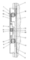
- FIG. 1 shows in a single figure 3 schematically shows an inventive edge gear arranged in a wing with a transmission gear
- An arranged in a wing 1 of a window, a French window or the like edge gear 2 is used to drive two counter-rotating drive rods 3, 4 of an espagnolette fitting.
- the drive rods 3, 4 are used to control arranged at the ends of the wing 1 closing devices with which the wing 1 can be locked in a frame.
- the wing 1 has a fitting groove 5 for receiving the drive rods 3, 4 and a portion of the edge gear 2.
- the edge gear 2 has two with the drive rods 3, 4 in engagement drive pinion 6, 7 and with a handle, not shown, for driving the drive pinion 6, 7 provided second pinion 8 and a transmission gear 9.
- a arranged in the second pinion 8 drive recess 10th serves to connect to the handle.
- the second pinion 8 drives via a rack drive 11 to a coupling part 12, which moves a first drive pinion 6 via a rotation axis 13.
- the first drive pinion 6 is engaged with a first drive rod 3 and a counterpart 14.
- the driving gear 6 meshing with the fixed counterpart 14 forms the transmission gear 9, which increases the path with which the first drive rod 6 is driven, compared to the path of the coupling part 12.
- the edge gear 2 has a reverse gear 15 with the second drive pinion 7 for driving the second drive rod 7.
- the second drive pinion 7 is formed as an intermediate gear with a non-displaceable mounting 16, which is connected to a connected to the first drive rod 6 coupling part 17 and the second drive rod 4th engaged.
- the second drive pinion 7 changes the direction of movement of the second drive rod 4 relative to the first drive rod 3.
- the coupling member 17 has a rack portion 18.
- the edge gear 2 shown in Figure 1 has a so-called negative backset, in which the axis of rotation 19 of the driven by the handle second pinion 8 is arranged above the fitting groove 5.
- the second pinion 8 has a partial toothed rim 20 extending exclusively over an angular range of 90 °.
Landscapes
- Engineering & Computer Science (AREA)
- Mechanical Engineering (AREA)
- Transmission Devices (AREA)
- Toys (AREA)
- Mechanical Control Devices (AREA)
- Switches With Compound Operations (AREA)
- Polysaccharides And Polysaccharide Derivatives (AREA)
Abstract
Description
- Die Erfindung betrifft ein Kantengetriebe für einen Treibstangenbeschlag eines Fensters, entsprechend der DE 103 54 185.3 einer Fenstertür oder dergleichen mit einem Antriebsritzel und mit einer Aufnahme für eine Handhabe zum Antrieb des Antriebsritzels und mit einem mit dem Antriebsritzel in Eingriff stehenden Treibstangenabschnitt, wobei die Aufnahme für die Handhabe auf einem zweiten Ritzel angeordnet ist und zwischen dem zweiten Ritzel und dem Antriebsritzel ein Übersetzungsgetriebe angeordnet ist.
- Bei dem in der deutschen Patentanmeldung DE 103 54 185.3 beschriebenen Kantengetriebe lässt sich der vorgesehene Weg der Treibstange bei begrenztem Schwenkwinkel der Handhabe durch eine entsprechende Auslegung des Übersetzungsgetriebes einfach einstellen. Hierdurch kann der Durchmesser des Antriebsritzels besonders klein gehalten werden. Bei einem Kantengetriebe mit einem sogenannten negativen Dornmaß, bei dem die Drehachse der Handhabe oberhalb einer die Treibstange aufnehmenden Beschlagnut angeordnet ist, führt der kleine Durchmesser des Antriebsritzels zudem zu einem besonders geringen Überstand des Kantengetriebes über die Beschlagnut. Damit lässt sich das Kantengetriebe auch in einem zweiflügeligen Fenster ohne Mittelpfosten in einem Spalt zwischen den zwei Flügeln des Fensters anordnen. Das in der genannten deutschen Patentanmeldung beschriebene Kantengetriebe ist jedoch ausschließlich für einen Treibstangenbeschlag mit einer einzigen Treibstange vorgesehen. Häufig weisen jedoch Fenster auch zwei gegenläufig zueinander bewegbare Treibstangen auf, welche am oberen und unteren Ende des Flügels einen Formschluss mit einem Rahmen erzeugen. Daher soll das in der genannten deutschen Patentanmeldung beschriebene Kantengetriebe für einen Treibstangenbeschlag mit zwei gegenläufig zueinander bewegbaren Treibstangen weiterentwickelt werden.
- Ein Kantengetriebe für zwei gegenläufige Treibstangen ist beispielsweise aus der DE 92 07 895 U1 bekannt. Hierbei treibt das zweite Ritzel ein mit einer ersten Treibstange gekoppeltes Schiebestück und ein Umkehrgetriebe mit zwei Zwischenzahnrädern an. Die Zwischenzahnräder treiben ein weiteres Zahnrad an, welches mit der zweiten Treibstange gekoppelt ist. Dieses Kantengetriebe weist jedoch eine Vielzahl zu lagernder Zahnräder auf und ist daher störanfällig und kostenintensiv in der Fertigung.
- Der Erfindung liegt das Problem zugrunde, ein Kantengetriebe der eingangs genannten Art so weiterzubilden, dass es bei einem Antrieb zweier gegenläufiger Treibstangen sehr einfach aufgebaut und besonders störunanfällig ist.
- Dieses Problem wird erfindungsgemäß dadurch gelöst, dass eine zweite Treibstange über ein Umkehrgetriebe gegenläufig zur ersten Treibstange geführt ist, dass die erste Treibstange oder das zweite Ritzel mit einem verschieblichen Koppelteil verbunden ist, dass das verschiebliche Koppelteil mit dem Umkehrgetriebe in Eingriff steht und dass das zweite Ritzel ausschließlich mit dem Koppelteil in Eingriff steht.
- Durch diese Gestaltung wird das Umkehrgetriebe über das Koppelteil angetrieben. Hierdurch weist das erfindungsgemäße Kantengetriebe eine besonders geringe Anzahl von Bauteilen auf und lässt sich daher besonders kostengünstig fertigen. Die verschiebliche Führung des Koppelteils ist zudem besonders störunanfällig. Der Antrieb eines einzigen Bauteils über das zweite Ritzel führt zu einer weiteren beträchtlichen Vereinfachung des Aufbaus des erfindungsgemäßen Kantengetriebes.
- Der Antrieb der zweiten Treibstange gestaltet sich konstruktiv besonders einfach, wenn das Umkehrgetriebe als zweites Übersetzungsgetriebe mit demselben Übersetzungsverhältnis wie das erste Übersetzungsgetriebe und der entgegengesetzten Drehrichtung ausgebildet ist.
- Der Antrieb des Koppelteils erfordert gemäß einer anderen vorteilhaften Weiterbildung der Erfindung einen besonders geringen baulichen Aufwand, wenn das Koppelteil und das zweite Ritzel einen Zahnstangenantrieb aufweisen.
- Zur weiteren Verringerung der Fertigungskosten des erfindungsgemäßen Kantengetriebes trägt es bei, wenn das Koppelteil einstückig mit der ersten Treibstange gefertigt ist und das zweite Antriebsritzel antreibt und wenn das zweite Antriebsritzel eine feststehende Lagerung aufweist.
- Das erfindungsgemäße Kantengetriebe erfordert nur ein einziges Übersetzungsgetriebe, wenn das zweite Antriebsritzel als Zwischenzahnrad zur Umkehr der Bewegungsrichtung der zweiten Treibstange ausgebildet ist. Hierdurch bildet das Zwischenzahnrad und das das Zwischenzahnrad übergreifende Koppelteil der ersten Treibstange das Umkehrgetriebe, welches die zweite Treibstange entgegengesetzt zur ersten Treibstange antreibt.
- Die Erfindung lässt zahlreiche Ausführungsformen zu. Zur weiteren Verdeutlichung ihres Grundprinzips sind zwei davon in der Zeichnung dargestellt und werden nachfolgend beschrieben. Diese zeigt in einer einzigen Figur
schematisch ein erfindungsgemäßes, in einem Flügel angeordnetes Kantengetriebe mit einem Übersetzungsgetriebe, - Ein in einem Flügel 1 eines Fensters, einer Fenstertür oder dergleichen angeordnetes Kantengetriebe 2 dient zum Antrieb zweier gegenläufig geführter Treibstangen 3, 4 eines Treibstangenbeschlages. Die Treibstangen 3, 4 dienen zum Ansteuern von an den Enden des Flügels 1 angeordneten Schließeinrichtungen, mit denen der Flügel 1 in einem Rahmen verriegelt werden kann. Der Flügel 1 weist eine Beschlagnut 5 zur Aufnahme der Treibstangen 3, 4 und eines Teilbereichs des Kantengetriebes 2 auf. Das Kantengetriebe 2 hat zwei mit den Treibstangen 3, 4 in Eingriff stehende Antriebsritzel 6, 7 und ein mit einer nicht dargestellten Handhabe zum Antrieb der Antriebsritzel 6, 7 vorgesehenes zweites Ritzel 8 und ein Übersetzungsgetriebe 9. Eine in dem zweiten Ritzel 8 angeordnete Antriebsausnehmung 10 dient zur Verbindung mit der Handhabe. Das zweite Ritzel 8 treibt über einen Zahnstangenantrieb 11 ein Koppelteil 12 an, welches über eine Drehachse 13 ein erstes Antriebsritzels 6 verschiebt. Das erste Antriebsritzel 6 steht mit einer ersten Treibstange 3 und einem Gegenstück 14 in Eingriff. Das mit dem feststehenden Gegenstück 14 in Eingriff stehende Antriebsritzel 6 bildet das Übersetzungsgetriebe 9, welches den Weg, mit dem die erste Treibstange 6 angetrieben wird, gegenüber dem Weg des Koppelteils 12 vergrößert. Weiterhin hat das Kantengetriebe 2 ein Umkehrgetriebe 15 mit dem zweiten Antriebsritzel 7 zum Antrieb der zweiten Treibstange 7. Das zweite Antriebsritzel 7 ist als Zwischenzahnrad mit einer unverschieblichen Lagerung 16 ausgebildet, welches mit einem mit der ersten Treibstange 6 verbundenen Koppelteil 17 und der zweiten Treibstange 4 in Eingriff steht. Das zweite Antriebsritzel 7 ändert die Bewegungsrichtung der zweiten Treibstange 4 gegenüber der ersten Treibstange 3. Zum Eingriff in das zweite Antriebsritzel 7 weist das Koppelteil 17 einen Zahnstangenabschnitt 18 auf.
- Das in Figur 1 dargestellte Kantengetriebe 2 weist ein sogenanntes negatives Dornmaß auf, bei dem die Drehachse 19 des von der Handhabe angetriebenen zweiten Ritzels 8 oberhalb der Beschlagnut 5 angeordnet ist. Um den Überstand des Kantengetriebes 2 über der Beschlagnut 5 möglichst gering zu halten, weist das zweite Ritzel 8 einen sich ausschließlich über einen Winkelbereich von 90° erstreckenden Teilzahnkranz 20 auf.
Claims (5)
- Kantengetriebe für einen Treibstangenbeschlag eines Fensters, entsprechend der DE 103 54 185.3 einer Fenstertür oder dergleichen mit einem Antriebsritzel und mit einer Aufnahme für eine Handhabe zum Antrieb des Antriebsritzels und mit einem mit dem Antriebsritzel in Eingriff stehenden Treibstangenabschnitt, wobei die Aufnahme für die Handhabe auf einem zweiten Ritzel angeordnet ist und zwischen dem zweiten Ritzel und dem Antriebsritzel ein Übersetzungsgetriebe angeordnet ist, dadurch gekennzeichnet, dass eine zweite Treibstange (4) über ein Umkehrgetriebe (15) gegenläufig zur ersten Treibstange (3) geführt ist, dass die erste Treibstange (3) oder das zweite Ritzel (8) mit einem verschieblichen Koppelteil (17) verbunden ist, dass das verschiebliche Koppelteil (17) mit dem Umkehrgetriebe (15) in Eingriff steht und dass das zweite Ritzel (8) ausschließlich mit dem Koppelteil (17) in Eingriff steht.
- Kantengetriebe nach Anspruch 1, dadurch gekennzeichnet, dass das Umkehrgetriebe als zweites Übersetzungsgetriebe mit demselben Übersetzungsverhältnis wie das erste Übersetzungsgetriebe und der entgegengesetzten Drehrichtung ausgebildet ist.
- Kantengetriebe nach Anspruch 1 oder 2, dadurch gekennzeichnet, dass das Koppelteil (17) und das zweite Ritzel (8) einen Zahnstangenantrieb (11) aufweisen.
- Kantengetriebe nach zumindest einem der vorhergehenden Ansprüche, dadurch gekennzeichnet, dass das Koppelteil (17) einstückig mit der ersten Treibstange (3) gefertigt ist und das zweite Antriebsritzel (7) antreibt und dass das zweite Antriebsritzel (7) eine feststehende Lagerung (16) aufweist.
- Kantengetriebe nach zumindest einem der vorhergehenden Ansprüche, dadurch gekennzeichnet, dass das zweite Antriebsritzel (7) als Zwischenzahnrad zur Umkehr der Bewegungsrichtung der zweiten Treibstange (4) ausgebildet ist.
Applications Claiming Priority (1)
| Application Number | Priority Date | Filing Date | Title |
|---|---|---|---|
| DE200410032307 DE102004032307A1 (de) | 2003-11-20 | 2004-07-03 | Kantengetriebe |
Publications (2)
| Publication Number | Publication Date |
|---|---|
| EP1619330A1 true EP1619330A1 (de) | 2006-01-25 |
| EP1619330B1 EP1619330B1 (de) | 2007-08-08 |
Family
ID=35351720
Family Applications (1)
| Application Number | Title | Priority Date | Filing Date |
|---|---|---|---|
| EP05104848A Expired - Lifetime EP1619330B1 (de) | 2004-07-03 | 2005-06-03 | Kantengetriebe |
Country Status (3)
| Country | Link |
|---|---|
| EP (1) | EP1619330B1 (de) |
| AT (1) | ATE369475T1 (de) |
| DE (1) | DE502005001169D1 (de) |
Citations (4)
| Publication number | Priority date | Publication date | Assignee | Title |
|---|---|---|---|---|
| US5102174A (en) * | 1990-02-05 | 1992-04-07 | Ferco International Usine De Ferrures De Batiment | Gearing for espagnolette fitting |
| DE9207895U1 (de) * | 1992-06-12 | 1992-09-03 | Gebr. Goldschmidt Baubeschläge GmbH, 5628 Heiligenhaus | Aufsatzgetriebe eines Fenster- oder Türbeschlages |
| EP0564863A1 (de) * | 1992-04-06 | 1993-10-13 | SCHÜCO International KG | Antrieb eines Riegelstangenbeschlages eines Fensters oder einer Tür |
| DE10354185A1 (de) * | 2003-11-20 | 2005-06-23 | Aug. Winkhaus Gmbh & Co. Kg | Kantengetriebe |
-
2005
- 2005-06-03 EP EP05104848A patent/EP1619330B1/de not_active Expired - Lifetime
- 2005-06-03 AT AT05104848T patent/ATE369475T1/de not_active IP Right Cessation
- 2005-06-03 DE DE502005001169T patent/DE502005001169D1/de not_active Expired - Lifetime
Patent Citations (4)
| Publication number | Priority date | Publication date | Assignee | Title |
|---|---|---|---|---|
| US5102174A (en) * | 1990-02-05 | 1992-04-07 | Ferco International Usine De Ferrures De Batiment | Gearing for espagnolette fitting |
| EP0564863A1 (de) * | 1992-04-06 | 1993-10-13 | SCHÜCO International KG | Antrieb eines Riegelstangenbeschlages eines Fensters oder einer Tür |
| DE9207895U1 (de) * | 1992-06-12 | 1992-09-03 | Gebr. Goldschmidt Baubeschläge GmbH, 5628 Heiligenhaus | Aufsatzgetriebe eines Fenster- oder Türbeschlages |
| DE10354185A1 (de) * | 2003-11-20 | 2005-06-23 | Aug. Winkhaus Gmbh & Co. Kg | Kantengetriebe |
Also Published As
| Publication number | Publication date |
|---|---|
| DE502005001169D1 (de) | 2007-09-20 |
| ATE369475T1 (de) | 2007-08-15 |
| EP1619330B1 (de) | 2007-08-08 |
Similar Documents
| Publication | Publication Date | Title |
|---|---|---|
| DE102015107955A1 (de) | Elektrische Antriebseinheit | |
| EP2058461A2 (de) | Treibstangengetriebe | |
| EP0150392A2 (de) | Federtriebwerk für Fahrspielzeuge | |
| EP0598927B1 (de) | Betätigungsgetriebe für Beschläge an Fenstern, Türen oder dergleichen | |
| EP2921622B1 (de) | Treibriegelbeschlag | |
| EP2735678B1 (de) | Beschlag für Fenster, Türen oder dergleichen | |
| EP1619330B1 (de) | Kantengetriebe | |
| DE102004032307A1 (de) | Kantengetriebe | |
| EP3736400B1 (de) | Entriegelungsvorrichtung mit automatischem antrieb | |
| DE10354185B4 (de) | Kantengetriebe | |
| DE69512998T2 (de) | Verschluss für Tür, Fenster oder Dgl. | |
| EP4004314A1 (de) | Antriebseinheit für kraftfahrzeugtechnische anwendungen | |
| DE1244611B (de) | Betaetigungsgetriebe fuer laengsverschiebbare Treibstangen an Fenstern, Tueren, Klappen od. dgl., insbesondere fuer Kipp-Schwenkfluegel | |
| EP1288418B1 (de) | Beschlagseinheit für ein Kipp- oder Drehkippfenster | |
| EP0736657A1 (de) | Öffenbarer Fensterflügel/Türflügel | |
| EP3162994B1 (de) | Antriebsgetriebe für einen treibstangenbeschlag | |
| EP3246499B1 (de) | Zur montage in einer einen hinterschnitt aufweisenden beschlagnut vorgesehenes beschlagteil | |
| EP1533454B1 (de) | Treibstangenbeschlag | |
| EP0922827B1 (de) | Gegenläufiges Treibstangengetriebe mit Offset-Getriebekasten | |
| EP3128109B1 (de) | Antriebsgetriebe für einen treibstangenbeschlag | |
| DE2923460C2 (de) | Rechts und links verwendbares Drehstangenschloß | |
| DE1266173B (de) | Getriebe eines Treibstangenbeschlages fuer Fenster, Tueren od. dgl., insbesondere fuer Kipp-Schwenkfluegel-Fenster | |
| DE102004059837A1 (de) | Treibstangenantrieb | |
| DE202004010424U1 (de) | Antriebseinrichtung für einen Treibstangenbeschlag | |
| EP0367842A1 (de) | Handhebelgetriebe zum Aufschrauben auf den Flügelrahmen von Fenstern, Türen oder dergleichen |
Legal Events
| Date | Code | Title | Description |
|---|---|---|---|
| PUAI | Public reference made under article 153(3) epc to a published international application that has entered the european phase |
Free format text: ORIGINAL CODE: 0009012 |
|
| AK | Designated contracting states |
Kind code of ref document: A1 Designated state(s): AT BE BG CH CY CZ DE DK EE ES FI FR GB GR HU IE IS IT LI LT LU MC NL PL PT RO SE SI SK TR |
|
| AX | Request for extension of the european patent |
Extension state: AL BA HR LV MK YU |
|
| 17P | Request for examination filed |
Effective date: 20060626 |
|
| AKX | Designation fees paid |
Designated state(s): AT BE BG CH CY CZ DE DK EE ES FI FR GB GR HU IE IS IT LI LT LU MC NL PL PT RO SE SI SK TR |
|
| GRAP | Despatch of communication of intention to grant a patent |
Free format text: ORIGINAL CODE: EPIDOSNIGR1 |
|
| GRAS | Grant fee paid |
Free format text: ORIGINAL CODE: EPIDOSNIGR3 |
|
| GRAA | (expected) grant |
Free format text: ORIGINAL CODE: 0009210 |
|
| AK | Designated contracting states |
Kind code of ref document: B1 Designated state(s): AT BE BG CH CY CZ DE DK EE ES FI FR GB GR HU IE IS IT LI LT LU MC NL PL PT RO SE SI SK TR |
|
| REG | Reference to a national code |
Ref country code: GB Ref legal event code: FG4D Free format text: NOT ENGLISH |
|
| GBT | Gb: translation of ep patent filed (gb section 77(6)(a)/1977) |
Effective date: 20070808 |
|
| REG | Reference to a national code |
Ref country code: CH Ref legal event code: EP |
|
| REG | Reference to a national code |
Ref country code: IE Ref legal event code: FG4D Free format text: LANGUAGE OF EP DOCUMENT: GERMAN |
|
| REF | Corresponds to: |
Ref document number: 502005001169 Country of ref document: DE Date of ref document: 20070920 Kind code of ref document: P |
|
| REG | Reference to a national code |
Ref country code: DE Ref legal event code: R096 Ref document number: 502005001169 Country of ref document: DE Effective date: 20070920 |
|
| ET | Fr: translation filed | ||
| PG25 | Lapsed in a contracting state [announced via postgrant information from national office to epo] |
Ref country code: NL Free format text: LAPSE BECAUSE OF FAILURE TO SUBMIT A TRANSLATION OF THE DESCRIPTION OR TO PAY THE FEE WITHIN THE PRESCRIBED TIME-LIMIT Effective date: 20070808 Ref country code: LT Free format text: LAPSE BECAUSE OF FAILURE TO SUBMIT A TRANSLATION OF THE DESCRIPTION OR TO PAY THE FEE WITHIN THE PRESCRIBED TIME-LIMIT Effective date: 20070808 Ref country code: ES Free format text: LAPSE BECAUSE OF FAILURE TO SUBMIT A TRANSLATION OF THE DESCRIPTION OR TO PAY THE FEE WITHIN THE PRESCRIBED TIME-LIMIT Effective date: 20071119 Ref country code: IS Free format text: LAPSE BECAUSE OF FAILURE TO SUBMIT A TRANSLATION OF THE DESCRIPTION OR TO PAY THE FEE WITHIN THE PRESCRIBED TIME-LIMIT Effective date: 20071208 Ref country code: BG Free format text: LAPSE BECAUSE OF FAILURE TO SUBMIT A TRANSLATION OF THE DESCRIPTION OR TO PAY THE FEE WITHIN THE PRESCRIBED TIME-LIMIT Effective date: 20071108 Ref country code: FI Free format text: LAPSE BECAUSE OF FAILURE TO SUBMIT A TRANSLATION OF THE DESCRIPTION OR TO PAY THE FEE WITHIN THE PRESCRIBED TIME-LIMIT Effective date: 20070808 |
|
| NLV1 | Nl: lapsed or annulled due to failure to fulfill the requirements of art. 29p and 29m of the patents act | ||
| PG25 | Lapsed in a contracting state [announced via postgrant information from national office to epo] |
Ref country code: PL Free format text: LAPSE BECAUSE OF FAILURE TO SUBMIT A TRANSLATION OF THE DESCRIPTION OR TO PAY THE FEE WITHIN THE PRESCRIBED TIME-LIMIT Effective date: 20070808 |
|
| REG | Reference to a national code |
Ref country code: IE Ref legal event code: FD4D |
|
| PG25 | Lapsed in a contracting state [announced via postgrant information from national office to epo] |
Ref country code: DK Free format text: LAPSE BECAUSE OF FAILURE TO SUBMIT A TRANSLATION OF THE DESCRIPTION OR TO PAY THE FEE WITHIN THE PRESCRIBED TIME-LIMIT Effective date: 20070808 Ref country code: GR Free format text: LAPSE BECAUSE OF FAILURE TO SUBMIT A TRANSLATION OF THE DESCRIPTION OR TO PAY THE FEE WITHIN THE PRESCRIBED TIME-LIMIT Effective date: 20071109 |
|
| PG25 | Lapsed in a contracting state [announced via postgrant information from national office to epo] |
Ref country code: SK Free format text: LAPSE BECAUSE OF FAILURE TO SUBMIT A TRANSLATION OF THE DESCRIPTION OR TO PAY THE FEE WITHIN THE PRESCRIBED TIME-LIMIT Effective date: 20070808 Ref country code: CZ Free format text: LAPSE BECAUSE OF FAILURE TO SUBMIT A TRANSLATION OF THE DESCRIPTION OR TO PAY THE FEE WITHIN THE PRESCRIBED TIME-LIMIT Effective date: 20070808 Ref country code: IE Free format text: LAPSE BECAUSE OF FAILURE TO SUBMIT A TRANSLATION OF THE DESCRIPTION OR TO PAY THE FEE WITHIN THE PRESCRIBED TIME-LIMIT Effective date: 20070808 Ref country code: PT Free format text: LAPSE BECAUSE OF FAILURE TO SUBMIT A TRANSLATION OF THE DESCRIPTION OR TO PAY THE FEE WITHIN THE PRESCRIBED TIME-LIMIT Effective date: 20080108 |
|
| PLBE | No opposition filed within time limit |
Free format text: ORIGINAL CODE: 0009261 |
|
| STAA | Information on the status of an ep patent application or granted ep patent |
Free format text: STATUS: NO OPPOSITION FILED WITHIN TIME LIMIT |
|
| PG25 | Lapsed in a contracting state [announced via postgrant information from national office to epo] |
Ref country code: RO Free format text: LAPSE BECAUSE OF FAILURE TO SUBMIT A TRANSLATION OF THE DESCRIPTION OR TO PAY THE FEE WITHIN THE PRESCRIBED TIME-LIMIT Effective date: 20070808 Ref country code: SE Free format text: LAPSE BECAUSE OF FAILURE TO SUBMIT A TRANSLATION OF THE DESCRIPTION OR TO PAY THE FEE WITHIN THE PRESCRIBED TIME-LIMIT Effective date: 20071108 |
|
| 26N | No opposition filed |
Effective date: 20080509 |
|
| REG | Reference to a national code |
Ref country code: DE Ref legal event code: R097 Ref document number: 502005001169 Country of ref document: DE Effective date: 20080509 |
|
| BERE | Be: lapsed |
Owner name: AUG. WINKHAUS G.M.B.H. & CO. KG Effective date: 20080630 |
|
| PG25 | Lapsed in a contracting state [announced via postgrant information from national office to epo] |
Ref country code: MC Free format text: LAPSE BECAUSE OF NON-PAYMENT OF DUE FEES Effective date: 20080630 |
|
| PG25 | Lapsed in a contracting state [announced via postgrant information from national office to epo] |
Ref country code: BE Free format text: LAPSE BECAUSE OF NON-PAYMENT OF DUE FEES Effective date: 20080630 |
|
| PG25 | Lapsed in a contracting state [announced via postgrant information from national office to epo] |
Ref country code: EE Free format text: LAPSE BECAUSE OF FAILURE TO SUBMIT A TRANSLATION OF THE DESCRIPTION OR TO PAY THE FEE WITHIN THE PRESCRIBED TIME-LIMIT Effective date: 20070808 |
|
| PG25 | Lapsed in a contracting state [announced via postgrant information from national office to epo] |
Ref country code: SI Free format text: LAPSE BECAUSE OF FAILURE TO SUBMIT A TRANSLATION OF THE DESCRIPTION OR TO PAY THE FEE WITHIN THE PRESCRIBED TIME-LIMIT Effective date: 20070808 |
|
| PG25 | Lapsed in a contracting state [announced via postgrant information from national office to epo] |
Ref country code: CY Free format text: LAPSE BECAUSE OF FAILURE TO SUBMIT A TRANSLATION OF THE DESCRIPTION OR TO PAY THE FEE WITHIN THE PRESCRIBED TIME-LIMIT Effective date: 20070808 |
|
| PG25 | Lapsed in a contracting state [announced via postgrant information from national office to epo] |
Ref country code: AT Free format text: LAPSE BECAUSE OF NON-PAYMENT OF DUE FEES Effective date: 20080603 |
|
| REG | Reference to a national code |
Ref country code: CH Ref legal event code: PL |
|
| PG25 | Lapsed in a contracting state [announced via postgrant information from national office to epo] |
Ref country code: LI Free format text: LAPSE BECAUSE OF NON-PAYMENT OF DUE FEES Effective date: 20090630 Ref country code: CH Free format text: LAPSE BECAUSE OF NON-PAYMENT OF DUE FEES Effective date: 20090630 |
|
| PG25 | Lapsed in a contracting state [announced via postgrant information from national office to epo] |
Ref country code: LU Free format text: LAPSE BECAUSE OF NON-PAYMENT OF DUE FEES Effective date: 20080603 Ref country code: HU Free format text: LAPSE BECAUSE OF FAILURE TO SUBMIT A TRANSLATION OF THE DESCRIPTION OR TO PAY THE FEE WITHIN THE PRESCRIBED TIME-LIMIT Effective date: 20080209 |
|
| PG25 | Lapsed in a contracting state [announced via postgrant information from national office to epo] |
Ref country code: TR Free format text: LAPSE BECAUSE OF FAILURE TO SUBMIT A TRANSLATION OF THE DESCRIPTION OR TO PAY THE FEE WITHIN THE PRESCRIBED TIME-LIMIT Effective date: 20070808 |
|
| PG25 | Lapsed in a contracting state [announced via postgrant information from national office to epo] |
Ref country code: IT Free format text: LAPSE BECAUSE OF NON-PAYMENT OF DUE FEES Effective date: 20080630 |
|
| PGFP | Annual fee paid to national office [announced via postgrant information from national office to epo] |
Ref country code: GB Payment date: 20130701 Year of fee payment: 9 Ref country code: FR Payment date: 20130719 Year of fee payment: 9 |
|
| GBPC | Gb: european patent ceased through non-payment of renewal fee |
Effective date: 20140603 |
|
| REG | Reference to a national code |
Ref country code: FR Ref legal event code: ST Effective date: 20150227 |
|
| PG25 | Lapsed in a contracting state [announced via postgrant information from national office to epo] |
Ref country code: GB Free format text: LAPSE BECAUSE OF NON-PAYMENT OF DUE FEES Effective date: 20140603 Ref country code: FR Free format text: LAPSE BECAUSE OF NON-PAYMENT OF DUE FEES Effective date: 20140630 |
|
| PGFP | Annual fee paid to national office [announced via postgrant information from national office to epo] |
Ref country code: DE Payment date: 20210827 Year of fee payment: 17 |
|
| REG | Reference to a national code |
Ref country code: DE Ref legal event code: R119 Ref document number: 502005001169 Country of ref document: DE |
|
| PG25 | Lapsed in a contracting state [announced via postgrant information from national office to epo] |
Ref country code: DE Free format text: LAPSE BECAUSE OF NON-PAYMENT OF DUE FEES Effective date: 20230103 |
|
| P01 | Opt-out of the competence of the unified patent court (upc) registered |
Effective date: 20230515 |