EP1618918B1 - Electrode implantable - Google Patents
Electrode implantable Download PDFInfo
- Publication number
- EP1618918B1 EP1618918B1 EP05105557.2A EP05105557A EP1618918B1 EP 1618918 B1 EP1618918 B1 EP 1618918B1 EP 05105557 A EP05105557 A EP 05105557A EP 1618918 B1 EP1618918 B1 EP 1618918B1
- Authority
- EP
- European Patent Office
- Prior art keywords
- electrode
- magnesium
- alloy
- weight
- containing section
- Prior art date
- Legal status (The legal status is an assumption and is not a legal conclusion. Google has not performed a legal analysis and makes no representation as to the accuracy of the status listed.)
- Not-in-force
Links
Images

Classifications
-
- A—HUMAN NECESSITIES
- A61—MEDICAL OR VETERINARY SCIENCE; HYGIENE
- A61N—ELECTROTHERAPY; MAGNETOTHERAPY; RADIATION THERAPY; ULTRASOUND THERAPY
- A61N1/00—Electrotherapy; Circuits therefor
- A61N1/02—Details
- A61N1/04—Electrodes
- A61N1/05—Electrodes for implantation or insertion into the body, e.g. heart electrode
- A61N1/056—Transvascular endocardial electrode systems
- A61N1/0565—Electrode heads
Definitions
- implantable electrode which comprises at least one electrical conductor with a proximal connection region for a pulse generator and at least one working electrode which can be connected to the pulse generator via the conductor.
- the invention is defined in claim 1.
- Electrodes of the generic type are well known in the art. They are part of numerous functional electro-stimulation devices (FES), which are used for the electrical treatment of nerve or muscle cells in the diagnostic or therapeutic area.
- FES functional electro-stimulation devices
- Implant systems for functional electrostimulation include, for example, pacemakers with a pulse generator for artificially stimulating cardiac actions housed in a biocompatible housing with associated electronic circuitry and power supply. The housing has a connection point where the electrode is connected.
- electrode refers in medical technology not only the transition point of the electrical energy according to physical definition, but refers It also refers to the conductor consisting of the electrical conductor, including the surrounding insulation, as well as all the other functional elements permanently connected to the conductor. In the following, for purposes of clarification, the section of the electrode which actually acts in the physical sense and which comprises the transition point of the electrical energy is referred to as the "working electrode”.
- the materials suitable for the purpose of the use should have sufficient bioresistance and also good biocompatibility. It is therefore to be ensured that a long-term implantation in the body-that is to say in a highly corrosive environment-proceeds without appreciable degradation processes and does not lead to an undesired immunological reaction.
- Biocompatible plastics based on silicone, polycarbonates, epoxysilane, polyurethane, polysulfones, polyethylene and polyester can be used to insulate the electrical cable.
- the working electrodes which may be designed as leakage, stimulation and sensing electrodes, are generally formed based on biocompatible metals such as platinum, iridium titanium or gold.
- Materials for use in implants are acceptable if the surrounding tissue - even with an increased risk of allergies - only to a small extent with non-specific inflammation to mechanical disturbances and the presence of the material reacts.
- Electrodes have such areas, inter alia, at the connection points to the housing of the pulse generator, since there set the geometries of the components a "mechanically flexible deflection" of the electrode limits.
- Another area of special stress lies in the area of the working electrodes, which, in order to perform their function, must be in direct contact with the tissue to be stimulated. Again and again there are unwanted immunological and inflammatory reactions of the body.
- electrodes must often be provided with anchor elements or support structures to provide a relative spatial location of the working electrode to be treated To ensure tissue. Also in the areas of the support structures and anchoring elements, which can be configured in a very diverse manner, usually occur more immunological and inflammatory reactions.
- the present invention is therefore based on the object of further improving the compatibility of implanted electrodes which comprise at least one electrical conductor with a proximal connection region for a pulse generator and at least one working electrode which can be connected to the pulse generator via the conductor.
- the electrode having at least one portion containing elemental magnesium. It has surprisingly been found that elemental magnesium apparently exerts a positive effect on the surrounding tissue and counteracts a strong immunological and inflammatory reactions of the body on the presence of the electrode. The mechanism of action underlying the effect has not yet been established. The desired effect only occurs when the magnesium is present in elementary form, at least for a short time - whether as a pure element or as an alloy.
- the magnesium is preferably present in the form of a biodegradable magnesium alloy which contains at least 50% by weight, preferably at least 70% by weight, particularly preferably at least 85% by weight, of magnesium.
- Biodegradation is understood to mean hydrolytic, enzymatic and other metabolism-related degradation processes in the living organism, which lead to a gradual dissolution of at least large parts of the alloy.
- biocorrosion is often used synonymously.
- bioresorption additionally includes the subsequent absorption of the degradation products.
- the alloy is preferably of the type WE, ie it contains yttrium and rare earths as alloying components.
- the abovementioned alloys can be processed well and have an antiproliferative effect in in vitro experiments to detect smooth human muscle cells. They are thus particularly suitable for preventing unwanted reactions of the body to the presence of the electrode. It is possible that the processes involved in the decomposition of the alloy support or enhance the antiproliferative effect.
- the specific composition of the magnesium alloy and its modification are predefined in such a way that the decomposition starts immediately after implantation and is maintained until the electrode has been coated with connective tissue, at least in some areas. This period should preferably be between 1 to 90 days, in particular 3 to 30 days. The extent of the degradation processes depends on the conditions prevailing at the implantation site.
- An at least partial covering means that at least the areas of the magnesium-containing sections are covered with connective tissue for more than 50% of their area.
- the magnesium-containing portions of the electrode are individually adapted to the respective desired application in order to achieve the desired release behavior. It is known that a higher magnesium content leads to an increase in the decomposition rate. It is further known that the processing of the material, e.g. by extrusion, leads to a change in the metallic structure, and thus the decomposition can be influenced.
- the section may consist entirely or partially of magnesium or its alloys.
- the provision of magnesium or its alloys is in the form of small metal particles embedded in a biodegradable matrix. With decomposition of the matrix, the particles are released and also slowly degraded.
- the particles preferably have a diameter of 0.1 ⁇ m to 500 ⁇ m, in particular 1 ⁇ m to 50 ⁇ m.
- Hyaluronic acid and its derivatives are preferred as the matrix since this biopolymer degrades very rapidly and has a very high biocompatibility.
- a magnesium-containing "section” can take any geometry.
- the lead of the electrode i. the electrical conductor is coated with insulating material over its entire extent with magnesium or its alloys.
- the section into the electrode as an independent structural element, e.g. in the form of a ring drawn from the material at a predetermined point on the line.
- the magnesium-containing sections are arranged at the proximal end of the electrode, ie adjacent to the connection region of the pulse generator, are particularly suitable.
- preferred arrangements are those in which the sections are arranged next to the working electrodes.
- a magnesium-containing portion is arranged on or next to the anchor elements or support structures of the electrode.
- the magnesium-containing portion covers an electrically active surface of the working electrode.
- This area of the working electrode is particularly susceptible to immunological and inflammatory reactions after implantation and recording of its desired functionality, which in part lead to scarring of the tissue and thus can permanently affect the functionality of the working electrode.
- elemental magnesium does not substantially limit the functionality of drain electrodes, stimulation electrodes and measuring electrodes and thereby exerts a positive supressive effect on the immunological response of the surrounding tissue.
- the magnesium-containing portion is preferably only a few micrometers, in particular 10-100 microns thick.
- the section is further preferably designed such that it has decomposed to more than 90% by weight within 1 hour to 120 hours, in particular 12 hours to 36 hours.
- the just described preferred embodiments of the sections again consist in whole or in part of magnesium or its alloys.
- the active surface of the electrode preferably has cavities (pits, slots, holes) filled with magnesium (alloy).
- the entire active surface may still be provided with a very thin coating of magnesium. This dissolves quickly and causes in the first few days a relief of acute reactions. Subsequently, the magnesium in the cavities has a lower dose over a longer period of time (a few weeks).
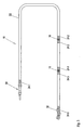
- Fig. 1 schematically shows a functional electro-stimulation device 10, which is designed for the electrical treatment of nerve or muscle cells, in particular for the artificial stimulation of heart actions.
- the electrical stimulation device 10 can be divided into a housing 12 and an electrode 16 connected to the housing 12 at a connection point 14.
- the housing 12 contains necessary components for the functionality of the electro-stimulation device 10, such as a pulse generator, electrical circuits and a power supply.
- the electrode 16 has at its proximal, ie connected to the housing 12 end suitable, not shown here closer structures that allow connection to the housing 12. Such structures are well known in the art and have been associated with the present invention no further meaning, so that a detailed description of the same is dispensed with.
- the electrode 16 has three working electrodes 18, 19, 20, which are understood to mean electrically conductive structural elements which comprise a transition point for the electrical energy.
- the two working electrodes 18, 19 are exemplified as ring electrodes and may consist of a platinum-iridium alloy, while the distal working electrode 20 forms a hemispherical head of the electrode 16 and consists of an iridium-coated platinum-iridium alloy.
- the working electrodes 18, 19, 20 may be designed as discharge, stimulation or measuring electrodes. It should be noted that the material, number, location and geometry of the working electrodes 18, 19, 20 can be varied widely without significant impact on the subject matter of the present invention.
- the electrode 16 further comprises a conduit 22 in which - not shown here - one or more electrical conductors extend, wherein the same of an insulator material, in particular based on plastic, are wrapped.
- the insulator material should have at least tolerable biocompatibility and sufficient bioresistance. Suitable materials for this purpose are well known to the person skilled in the art.
- the electrode 16 also shows six magnesium-containing sections 24.1 to 24.6.
- a first section 24. 1 is arranged adjacent to the connection point 14 of the housing 12, that is to say in the region of the proximal end of the electrode 16.
- the magnesium-containing sections 24.2 to 24.5 enclose the annular working electrodes 18 and 19.
- the section 24.6 directly adjoins the working electrode 20 at the distal end of the electrode 16.
- regions on the electrode 16 can be determined which, after implantation, are increasingly the starting point for tissue irritations in the surrounding tissue.
- the sections 24.1 to 24.6 now extend in particular over these areas or are arranged at least adjacent thereto. This is based on the knowledge that sections 24.1 to 24.6, containing elemental magnesium, become one significant reduction of irritation in the surrounding tissue.
- the entire line 22 may be coated with a coating containing elemental magnesium or a different structural element.
- Fig. 2 shows in a highly schematic manner a cross section through the line 22 of the electrode 16 in the region of a magnesium-containing portion 24.7.
- the electrical line 22 comprises a total of three electrical conductors 26, which are enveloped by an insulator material 28.
- the magnesium-containing portion 24.7 connects, which either consists of a coating of a mixed with small particles of magnesium, biodegradable matrix or massively designed as a sleeve of a biodegradable magnesium alloy.
- Fig. 3 shows a further electrode 16, wherein functionally the same type of component of the electrode 16 with the same reference numerals Fig. 1 were provided.
- the proximal connection region 30 of the electrode 16 in turn carries a magnesium-containing section 24.1.
- the two working electrodes 18, 19 are limited by magnesium-containing sections 24.2 to 24.5.
- the electrode 16 carries an anchor element 32, which tapers helically toward the tip of the electrode 16 and is intended to anchor in the surrounding tissue after or during implantation.
- the entire distal region of the electrode 16, in which the anchor element 32 is arranged, is covered by a magnesium-containing section 24.8.
- Section 24.8 can be realized as a coating of a biodegradable matrix with added magnesium particles.
- the variant 1 at Fig. 1 referenced approach the variant 1 at Fig. 1 referenced approach.
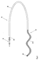
- Fig. 4 shows a further alternative embodiment of the electrode 16, in which a holding structure 34 is to hold the electrode 16 in a desired position after implantation.
- the support structure 34 is formed as a helical portion of the electrode 16 and should be able to be supported due to the shape of the surrounding tissue.
- the entire distal region of the electrode 16, which adjoins the working electrode 20, and thus the holding structure 34 is completed covered by a magnesium-containing section 24.9.
- the section 24.9 can again be in the form of a coating, as exemplified by the variant 1 of Fig. 1 is representable, covered.
Claims (12)
- Electrode (16) implantable, qui comprend au moins un conducteur électrique avec une zone de connexion proximale pour un générateur d'impulsions ainsi qu'au moins une électrode de travail pouvant être connectée avec le générateur d'impulsions par l'intermédiaire du conducteur, où l'électrode (16) comprend au moins une partie (24.1 à 24.9) qui contient du magnésium sous forme d'élément, caractérisée en ce que le magnésium est présent sous la forme d'un alliage biodégradable qui contient au moins 50 % en poids de magnésium.
- Electrode (16) selon la revendication 1, caractérisée en ce que l'alliage de magnésium contient au moins 70% en poids, de manière particulièrement préférée, au moins 85% en poids, de magnésium.
- Electrode (16) selon la revendication 2, caractérisée en ce que l'alliage de magnésium est un alliage du type WE.
- Electrode (16) selon l'une des revendications 1 à 3 caractérisée en ce qu'une partie contenant du magnésium (24.1 à 24.9) est disposée à l'extrémité proximale de l'électrode (16).
- Electrode (16) selon l'une des revendications 1 à 3, caractérisée en ce qu'une partie contenant du magnésium (24.1 à 24.9) est disposée à côté de l'électrode de travail (18, 19, 20).
- Electrode (16) selon l'une des revendications 1 à 3, caractérisée en ce qu'une partie contenant du magnésium (24.1 à 24.9) recouvre une surface électriquement active de l'électrode de travail (18, 19, 20).
- Electrode (16) selon la revendication 6, caractérisée en ce que la surface électriquement active de l'électrode de travail présente des cavités (creux, fentes, trous) qui sont remplies avec du magnésium en tant qu'élément pur ou avec des alliages de magnésium.
- Electrode (16) selon l'une des revendications 1 à 3, caractérisée en ce qu'une partie contenant du magnésium (24.1 à 24.9) est disposée sur ou au voisinage d'une structure support (34) ou d'un élément d'ancrage (32) de l'électrode (16).
- Electrode (16) selon l'une des revendications précédentes, caractérisée en ce que la partie contenant du magnésium a une épaisseur de 10 à 100 µm.
- Electrode (16) selon l'une des revendications précédentes, caractérisée en ce que la mise au point des alliages de magnésium est effectuée sous la forme de petites particules métalliques qui sont incorporées dans une matrice biodégradable.
- Electrode (16) selon la revendication 10, caractérisée en ce que les particules présentent un diamètre de 0,1 µm à 500 µm, de préférence de 1 µm à 50 µm
- Electrode (16) selon la revendication 10, caractérisée en ce que la matrice est de l'acide hyaluronique, en sus de ses dérivés.
Applications Claiming Priority (1)
| Application Number | Priority Date | Filing Date | Title |
|---|---|---|---|
| DE102004035904A DE102004035904A1 (de) | 2004-07-20 | 2004-07-20 | Implantierbare Elektrode |
Publications (2)
| Publication Number | Publication Date |
|---|---|
| EP1618918A1 EP1618918A1 (fr) | 2006-01-25 |
| EP1618918B1 true EP1618918B1 (fr) | 2015-09-16 |
Family
ID=34940220
Family Applications (1)
| Application Number | Title | Priority Date | Filing Date |
|---|---|---|---|
| EP05105557.2A Not-in-force EP1618918B1 (fr) | 2004-07-20 | 2005-06-22 | Electrode implantable |
Country Status (5)
| Country | Link |
|---|---|
| US (1) | US8660661B2 (fr) |
| EP (1) | EP1618918B1 (fr) |
| JP (1) | JP2006026416A (fr) |
| CN (1) | CN1724088B (fr) |
| DE (1) | DE102004035904A1 (fr) |
Families Citing this family (12)
| Publication number | Priority date | Publication date | Assignee | Title |
|---|---|---|---|---|
| US7879189B2 (en) * | 2005-12-15 | 2011-02-01 | Kimberly-Clark Worldwide, Inc. | Additive compositions for treating various base sheets |
| US8876861B2 (en) * | 2007-09-12 | 2014-11-04 | Transluminal Technologies, Inc. | Closure device, deployment apparatus, and method of deploying a closure device |
| MX2010002827A (es) | 2007-09-12 | 2010-08-31 | Transluminal Technologies Llc | Dispositivo de cierre, aparato de despliegue y metodo para despliegue de dispositivo de cierre. |
| US9456816B2 (en) | 2007-09-12 | 2016-10-04 | Transluminal Technologies, Llc | Closure device, deployment apparatus, and method of deploying a closure device |
| US8888841B2 (en) | 2010-06-21 | 2014-11-18 | Zorion Medical, Inc. | Bioabsorbable implants |
| MX356254B (es) | 2010-11-09 | 2018-05-21 | Transluminal Tech Llc | Aleaciones de magnesio-aluminio diseñadas especialmente y usos medicos de las mismas en un ambiente hemodinamico. |
| WO2012075311A2 (fr) | 2010-12-01 | 2012-06-07 | Zorion Medical, Inc. | Implants absorbables à base de magnésium |
| US10246763B2 (en) | 2012-08-24 | 2019-04-02 | The Regents Of The University Of California | Magnesium-zinc-strontium alloys for medical implants and devices |
| CN106782745B (zh) * | 2016-12-20 | 2019-07-05 | 南京心湃医疗科技有限公司 | 一种双极心脏起搏电流提供导线及单元、装置 |
| WO2018112767A1 (fr) * | 2016-12-20 | 2018-06-28 | 南京心湃医疗科技有限公司 | Fil de fourniture de courant de stimulation cardiaque, unité et dispositif |
| AU2018218261B2 (en) * | 2017-02-09 | 2020-06-11 | Med-El Elektromedizinische Geraete Gmbh | Dexamethasone coating for use with electrode carrier |
| CN109498984B (zh) * | 2017-09-15 | 2024-02-06 | 北京纳米能源与系统研究所 | 一体化可降解的电刺激导线及其制备方法 |
Citations (4)
| Publication number | Priority date | Publication date | Assignee | Title |
|---|---|---|---|---|
| US4011861A (en) * | 1974-04-03 | 1977-03-15 | Case Western Reserve University | Implantable electric terminal for organic tissue |
| US4273137A (en) * | 1979-12-17 | 1981-06-16 | Pravoverov Nikolai L | Electrical conductor for implantation into human body |
| US6463334B1 (en) * | 1998-11-02 | 2002-10-08 | Cardiac Pacemakers, Inc. | Extendable and retractable lead |
| WO2004112891A1 (fr) * | 2003-06-21 | 2004-12-29 | Biotronik Gmbh & Co. Kg | Electrode de stimulation implantable pourvue d'un revetement destine a augmenter la compatibilite tissulaire |
Family Cites Families (8)
| Publication number | Priority date | Publication date | Assignee | Title |
|---|---|---|---|---|
| DE2262674A1 (de) * | 1972-12-26 | 1974-06-27 | Burnel | Energieversorgungseinrichtung fuer einen herz-schrittmacher |
| US4314554A (en) | 1979-07-16 | 1982-02-09 | Greatbatch W | Tissue growth control apparatus and method |
| JPS62120403A (ja) | 1985-11-20 | 1987-06-01 | Permelec Electrode Ltd | 表面多孔質体チタン複合体の製造方法 |
| DD258658A1 (de) | 1986-01-27 | 1988-07-27 | Univ Berlin Humboldt | Verfahren zum pruefen von loetstellen elektronischer baugruppen |
| EP0966979B1 (fr) * | 1998-06-25 | 2006-03-08 | Biotronik AG | Support pour la paroi des vaisseaux implantable et biodégradable, notamment un extenseur coronaire |
| US6304786B1 (en) * | 1999-03-29 | 2001-10-16 | Cardiac Pacemakers, Inc. | Implantable lead with dissolvable coating for improved fixation and extraction |
| US6385491B1 (en) * | 1999-10-04 | 2002-05-07 | Medtronic, Inc. | Temporary medical electrical lead having biodegradable electrode mounting pad loaded with therapeutic drug |
| DE10253634A1 (de) * | 2002-11-13 | 2004-05-27 | Biotronik Meß- und Therapiegeräte GmbH & Co. Ingenieurbüro Berlin | Endoprothese |
-
2004
- 2004-07-20 DE DE102004035904A patent/DE102004035904A1/de not_active Withdrawn
-
2005
- 2005-06-22 EP EP05105557.2A patent/EP1618918B1/fr not_active Not-in-force
- 2005-07-19 JP JP2005209223A patent/JP2006026416A/ja active Pending
- 2005-07-20 CN CN2005100875038A patent/CN1724088B/zh not_active Expired - Fee Related
- 2005-07-20 US US11/185,144 patent/US8660661B2/en not_active Expired - Fee Related
Patent Citations (4)
| Publication number | Priority date | Publication date | Assignee | Title |
|---|---|---|---|---|
| US4011861A (en) * | 1974-04-03 | 1977-03-15 | Case Western Reserve University | Implantable electric terminal for organic tissue |
| US4273137A (en) * | 1979-12-17 | 1981-06-16 | Pravoverov Nikolai L | Electrical conductor for implantation into human body |
| US6463334B1 (en) * | 1998-11-02 | 2002-10-08 | Cardiac Pacemakers, Inc. | Extendable and retractable lead |
| WO2004112891A1 (fr) * | 2003-06-21 | 2004-12-29 | Biotronik Gmbh & Co. Kg | Electrode de stimulation implantable pourvue d'un revetement destine a augmenter la compatibilite tissulaire |
Also Published As
| Publication number | Publication date |
|---|---|
| DE102004035904A1 (de) | 2006-02-16 |
| EP1618918A1 (fr) | 2006-01-25 |
| CN1724088B (zh) | 2011-04-13 |
| US20060020315A1 (en) | 2006-01-26 |
| JP2006026416A (ja) | 2006-02-02 |
| CN1724088A (zh) | 2006-01-25 |
| US8660661B2 (en) | 2014-02-25 |
Similar Documents
| Publication | Publication Date | Title |
|---|---|---|
| EP1618918B1 (fr) | Electrode implantable | |
| DE102004062394B4 (de) | Intravenöse Herzschrittmacherelektrode und Verfahren zu deren Herstellung | |
| EP1618919B1 (fr) | Fixation pour électrodes et cathéters implantables | |
| EP2083911B1 (fr) | Implant retinien comprenant un corps principal | |
| DE4231600B4 (de) | Implantierbares Defibrillationssystem | |
| AT507045B1 (de) | Implantierbare, gewebe-stimulierende vorrichtung | |
| DE19916315A1 (de) | Verfahren zum Bilden einer dünnen keramikartigen Schicht auf einem Bioimplantat | |
| EP0966979A2 (fr) | Support pour la paroi des vaisseaux implantable et biodégradable, notamment un extenseur coronaire | |
| EP2399619B1 (fr) | Implant et son procédé de fabrication | |
| DE2262674A1 (de) | Energieversorgungseinrichtung fuer einen herz-schrittmacher | |
| FitzGerald | Suppression of scarring in peripheral nerve implants by drug elution | |
| EP2184082A1 (fr) | Ligne implantable | |
| EP2198899A2 (fr) | Convertisseur temps vers numérique et boucle numérique à phase asservie entièrement numérique | |
| DE102004035903A1 (de) | Fixierung für implantierbare Elektroden und Katheder | |
| WO2015162306A1 (fr) | Procédé de traitement de la surface d'un implant biocorrodable | |
| WO1999065537A1 (fr) | Implantation superficielle et revetement superficiel pour extenseurs et autres implants | |
| EP1878464B1 (fr) | Dispositif à électrodes implantable | |
| DE102007046879B4 (de) | Dentalimplantat | |
| DE102008010188A1 (de) | Verfahren zur Herstellung eines Isolationsschlauchs und Verfahren zur Herstellung einer Elektrode | |
| DE102009023163B4 (de) | Stimulationselektrode | |
| EP2476456A1 (fr) | Implant à électrodes ou à sondes auto-dégradable | |
| DE19721192C2 (de) | Biokompatible Barrieremembran | |
| EP2260883A2 (fr) | Système d'implant doté d'un implant temporaire et procédé d'influence du degré de corrosion d'un implant | |
| DE102022129920B3 (de) | Implantatsystem mit aktiv regulierbarer Degradation und Verfahren zur aktiv regulierbaren Degradation eines Implantatsystems | |
| DE102004035987A1 (de) | Fixierungseinrichtung mit einem Schutzelement |
Legal Events
| Date | Code | Title | Description |
|---|---|---|---|
| PUAI | Public reference made under article 153(3) epc to a published international application that has entered the european phase |
Free format text: ORIGINAL CODE: 0009012 |
|
| AK | Designated contracting states |
Kind code of ref document: A1 Designated state(s): AT BE BG CH CY CZ DE DK EE ES FI FR GB GR HU IE IS IT LI LT LU MC NL PL PT RO SE SI SK TR |
|
| AX | Request for extension of the european patent |
Extension state: AL BA HR LV MK YU |
|
| 17P | Request for examination filed |
Effective date: 20060421 |
|
| AKX | Designation fees paid |
Designated state(s): AT BE BG CH CY CZ DE DK EE ES FI FR GB GR HU IE IS IT LI LT LU MC NL PL PT RO SE SI SK TR |
|
| 17Q | First examination report despatched |
Effective date: 20080826 |
|
| GRAP | Despatch of communication of intention to grant a patent |
Free format text: ORIGINAL CODE: EPIDOSNIGR1 |
|
| INTG | Intention to grant announced |
Effective date: 20150616 |
|
| RIN1 | Information on inventor provided before grant (corrected) |
Inventor name: KUTTLER, MARC Inventor name: GEISTERT, WOLFGANG |
|
| GRAS | Grant fee paid |
Free format text: ORIGINAL CODE: EPIDOSNIGR3 |
|
| GRAA | (expected) grant |
Free format text: ORIGINAL CODE: 0009210 |
|
| AK | Designated contracting states |
Kind code of ref document: B1 Designated state(s): AT BE BG CH CY CZ DE DK EE ES FI FR GB GR HU IE IS IT LI LT LU MC NL PL PT RO SE SI SK TR |
|
| REG | Reference to a national code |
Ref country code: GB Ref legal event code: FG4D Free format text: NOT ENGLISH |
|
| REG | Reference to a national code |
Ref country code: CH Ref legal event code: EP |
|
| REG | Reference to a national code |
Ref country code: IE Ref legal event code: FG4D Free format text: LANGUAGE OF EP DOCUMENT: GERMAN |
|
| REG | Reference to a national code |
Ref country code: AT Ref legal event code: REF Ref document number: 749296 Country of ref document: AT Kind code of ref document: T Effective date: 20151015 |
|
| REG | Reference to a national code |
Ref country code: DE Ref legal event code: R096 Ref document number: 502005014933 Country of ref document: DE |
|
| REG | Reference to a national code |
Ref country code: NL Ref legal event code: MP Effective date: 20150916 |
|
| PG25 | Lapsed in a contracting state [announced via postgrant information from national office to epo] |
Ref country code: LT Free format text: LAPSE BECAUSE OF FAILURE TO SUBMIT A TRANSLATION OF THE DESCRIPTION OR TO PAY THE FEE WITHIN THE PRESCRIBED TIME-LIMIT Effective date: 20150916 Ref country code: GR Free format text: LAPSE BECAUSE OF FAILURE TO SUBMIT A TRANSLATION OF THE DESCRIPTION OR TO PAY THE FEE WITHIN THE PRESCRIBED TIME-LIMIT Effective date: 20151217 Ref country code: FI Free format text: LAPSE BECAUSE OF FAILURE TO SUBMIT A TRANSLATION OF THE DESCRIPTION OR TO PAY THE FEE WITHIN THE PRESCRIBED TIME-LIMIT Effective date: 20150916 |
|
| REG | Reference to a national code |
Ref country code: LT Ref legal event code: MG4D |
|
| PG25 | Lapsed in a contracting state [announced via postgrant information from national office to epo] |
Ref country code: SE Free format text: LAPSE BECAUSE OF FAILURE TO SUBMIT A TRANSLATION OF THE DESCRIPTION OR TO PAY THE FEE WITHIN THE PRESCRIBED TIME-LIMIT Effective date: 20150916 |
|
| PG25 | Lapsed in a contracting state [announced via postgrant information from national office to epo] |
Ref country code: NL Free format text: LAPSE BECAUSE OF FAILURE TO SUBMIT A TRANSLATION OF THE DESCRIPTION OR TO PAY THE FEE WITHIN THE PRESCRIBED TIME-LIMIT Effective date: 20150916 |
|
| PG25 | Lapsed in a contracting state [announced via postgrant information from national office to epo] |
Ref country code: ES Free format text: LAPSE BECAUSE OF FAILURE TO SUBMIT A TRANSLATION OF THE DESCRIPTION OR TO PAY THE FEE WITHIN THE PRESCRIBED TIME-LIMIT Effective date: 20150916 Ref country code: IT Free format text: LAPSE BECAUSE OF FAILURE TO SUBMIT A TRANSLATION OF THE DESCRIPTION OR TO PAY THE FEE WITHIN THE PRESCRIBED TIME-LIMIT Effective date: 20150916 Ref country code: SK Free format text: LAPSE BECAUSE OF FAILURE TO SUBMIT A TRANSLATION OF THE DESCRIPTION OR TO PAY THE FEE WITHIN THE PRESCRIBED TIME-LIMIT Effective date: 20150916 Ref country code: CZ Free format text: LAPSE BECAUSE OF FAILURE TO SUBMIT A TRANSLATION OF THE DESCRIPTION OR TO PAY THE FEE WITHIN THE PRESCRIBED TIME-LIMIT Effective date: 20150916 Ref country code: IS Free format text: LAPSE BECAUSE OF FAILURE TO SUBMIT A TRANSLATION OF THE DESCRIPTION OR TO PAY THE FEE WITHIN THE PRESCRIBED TIME-LIMIT Effective date: 20160116 Ref country code: EE Free format text: LAPSE BECAUSE OF FAILURE TO SUBMIT A TRANSLATION OF THE DESCRIPTION OR TO PAY THE FEE WITHIN THE PRESCRIBED TIME-LIMIT Effective date: 20150916 |
|
| PG25 | Lapsed in a contracting state [announced via postgrant information from national office to epo] |
Ref country code: PL Free format text: LAPSE BECAUSE OF FAILURE TO SUBMIT A TRANSLATION OF THE DESCRIPTION OR TO PAY THE FEE WITHIN THE PRESCRIBED TIME-LIMIT Effective date: 20150916 Ref country code: RO Free format text: LAPSE BECAUSE OF FAILURE TO SUBMIT A TRANSLATION OF THE DESCRIPTION OR TO PAY THE FEE WITHIN THE PRESCRIBED TIME-LIMIT Effective date: 20150916 Ref country code: PT Free format text: LAPSE BECAUSE OF FAILURE TO SUBMIT A TRANSLATION OF THE DESCRIPTION OR TO PAY THE FEE WITHIN THE PRESCRIBED TIME-LIMIT Effective date: 20160118 |
|
| REG | Reference to a national code |
Ref country code: DE Ref legal event code: R097 Ref document number: 502005014933 Country of ref document: DE |
|
| PLBE | No opposition filed within time limit |
Free format text: ORIGINAL CODE: 0009261 |
|
| STAA | Information on the status of an ep patent application or granted ep patent |
Free format text: STATUS: NO OPPOSITION FILED WITHIN TIME LIMIT |
|
| 26N | No opposition filed |
Effective date: 20160617 |
|
| PG25 | Lapsed in a contracting state [announced via postgrant information from national office to epo] |
Ref country code: DK Free format text: LAPSE BECAUSE OF FAILURE TO SUBMIT A TRANSLATION OF THE DESCRIPTION OR TO PAY THE FEE WITHIN THE PRESCRIBED TIME-LIMIT Effective date: 20150916 |
|
| PG25 | Lapsed in a contracting state [announced via postgrant information from national office to epo] |
Ref country code: SI Free format text: LAPSE BECAUSE OF FAILURE TO SUBMIT A TRANSLATION OF THE DESCRIPTION OR TO PAY THE FEE WITHIN THE PRESCRIBED TIME-LIMIT Effective date: 20150916 |
|
| PG25 | Lapsed in a contracting state [announced via postgrant information from national office to epo] |
Ref country code: BE Free format text: LAPSE BECAUSE OF NON-PAYMENT OF DUE FEES Effective date: 20160630 |
|
| PG25 | Lapsed in a contracting state [announced via postgrant information from national office to epo] |
Ref country code: MC Free format text: LAPSE BECAUSE OF FAILURE TO SUBMIT A TRANSLATION OF THE DESCRIPTION OR TO PAY THE FEE WITHIN THE PRESCRIBED TIME-LIMIT Effective date: 20150916 |
|
| GBPC | Gb: european patent ceased through non-payment of renewal fee |
Effective date: 20160622 |
|
| REG | Reference to a national code |
Ref country code: FR Ref legal event code: ST Effective date: 20170228 |
|
| PG25 | Lapsed in a contracting state [announced via postgrant information from national office to epo] |
Ref country code: FR Free format text: LAPSE BECAUSE OF NON-PAYMENT OF DUE FEES Effective date: 20160630 |
|
| PG25 | Lapsed in a contracting state [announced via postgrant information from national office to epo] |
Ref country code: GB Free format text: LAPSE BECAUSE OF NON-PAYMENT OF DUE FEES Effective date: 20160622 |
|
| REG | Reference to a national code |
Ref country code: AT Ref legal event code: MM01 Ref document number: 749296 Country of ref document: AT Kind code of ref document: T Effective date: 20160622 |
|
| PG25 | Lapsed in a contracting state [announced via postgrant information from national office to epo] |
Ref country code: AT Free format text: LAPSE BECAUSE OF NON-PAYMENT OF DUE FEES Effective date: 20160622 |
|
| REG | Reference to a national code |
Ref country code: DE Ref legal event code: R081 Ref document number: 502005014933 Country of ref document: DE Owner name: BIOTRONIK SE & CO. KG, DE Free format text: FORMER OWNER: BIOTRONIK CRM PATENT AG, BAAR, CH |
|
| PG25 | Lapsed in a contracting state [announced via postgrant information from national office to epo] |
Ref country code: CY Free format text: LAPSE BECAUSE OF FAILURE TO SUBMIT A TRANSLATION OF THE DESCRIPTION OR TO PAY THE FEE WITHIN THE PRESCRIBED TIME-LIMIT Effective date: 20150916 Ref country code: HU Free format text: LAPSE BECAUSE OF FAILURE TO SUBMIT A TRANSLATION OF THE DESCRIPTION OR TO PAY THE FEE WITHIN THE PRESCRIBED TIME-LIMIT; INVALID AB INITIO Effective date: 20050622 |
|
| PG25 | Lapsed in a contracting state [announced via postgrant information from national office to epo] |
Ref country code: TR Free format text: LAPSE BECAUSE OF FAILURE TO SUBMIT A TRANSLATION OF THE DESCRIPTION OR TO PAY THE FEE WITHIN THE PRESCRIBED TIME-LIMIT Effective date: 20150916 Ref country code: LU Free format text: LAPSE BECAUSE OF NON-PAYMENT OF DUE FEES Effective date: 20160622 |
|
| PG25 | Lapsed in a contracting state [announced via postgrant information from national office to epo] |
Ref country code: BG Free format text: LAPSE BECAUSE OF FAILURE TO SUBMIT A TRANSLATION OF THE DESCRIPTION OR TO PAY THE FEE WITHIN THE PRESCRIBED TIME-LIMIT Effective date: 20150916 |
|
| PGFP | Annual fee paid to national office [announced via postgrant information from national office to epo] |
Ref country code: DE Payment date: 20210625 Year of fee payment: 17 |
|
| PGFP | Annual fee paid to national office [announced via postgrant information from national office to epo] |
Ref country code: IE Payment date: 20210622 Year of fee payment: 17 Ref country code: CH Payment date: 20210623 Year of fee payment: 17 |
|
| REG | Reference to a national code |
Ref country code: DE Ref legal event code: R119 Ref document number: 502005014933 Country of ref document: DE |
|
| REG | Reference to a national code |
Ref country code: CH Ref legal event code: PL |
|
| PG25 | Lapsed in a contracting state [announced via postgrant information from national office to epo] |
Ref country code: LI Free format text: LAPSE BECAUSE OF NON-PAYMENT OF DUE FEES Effective date: 20220630 Ref country code: IE Free format text: LAPSE BECAUSE OF NON-PAYMENT OF DUE FEES Effective date: 20220622 Ref country code: CH Free format text: LAPSE BECAUSE OF NON-PAYMENT OF DUE FEES Effective date: 20220630 |
|
| PG25 | Lapsed in a contracting state [announced via postgrant information from national office to epo] |
Ref country code: DE Free format text: LAPSE BECAUSE OF NON-PAYMENT OF DUE FEES Effective date: 20230103 |