EP1617569A2 - Procédé pour la transmission des signaux d'information numériques avec une pluralité d'antennes - Google Patents
Procédé pour la transmission des signaux d'information numériques avec une pluralité d'antennes Download PDFInfo
- Publication number
- EP1617569A2 EP1617569A2 EP05014739A EP05014739A EP1617569A2 EP 1617569 A2 EP1617569 A2 EP 1617569A2 EP 05014739 A EP05014739 A EP 05014739A EP 05014739 A EP05014739 A EP 05014739A EP 1617569 A2 EP1617569 A2 EP 1617569A2
- Authority
- EP
- European Patent Office
- Prior art keywords
- transmission
- receiver
- signals
- time
- signal
- Prior art date
- Legal status (The legal status is an assumption and is not a legal conclusion. Google has not performed a legal analysis and makes no representation as to the accuracy of the status listed.)
- Granted
Links
- 238000000034 method Methods 0.000 title claims abstract description 85
- 230000005540 biological transmission Effects 0.000 title claims abstract description 78
- 238000012937 correction Methods 0.000 claims abstract description 3
- 125000004122 cyclic group Chemical group 0.000 claims description 16
- 238000004891 communication Methods 0.000 claims description 14
- 230000004048 modification Effects 0.000 claims description 5
- 238000012986 modification Methods 0.000 claims description 5
- 238000003491 array Methods 0.000 claims description 4
- 230000001413 cellular effect Effects 0.000 claims description 3
- 238000006073 displacement reaction Methods 0.000 claims description 2
- 238000012545 processing Methods 0.000 claims description 2
- 230000008054 signal transmission Effects 0.000 claims 1
- 238000012876 topography Methods 0.000 claims 1
- 238000001514 detection method Methods 0.000 abstract description 2
- 238000005562 fading Methods 0.000 description 38
- 238000004088 simulation Methods 0.000 description 15
- 230000002123 temporal effect Effects 0.000 description 13
- 230000008569 process Effects 0.000 description 10
- 238000001228 spectrum Methods 0.000 description 9
- 238000010586 diagram Methods 0.000 description 7
- 230000003595 spectral effect Effects 0.000 description 7
- 238000011161 development Methods 0.000 description 5
- 230000018109 developmental process Effects 0.000 description 5
- 230000000694 effects Effects 0.000 description 5
- 239000000969 carrier Substances 0.000 description 3
- 230000001934 delay Effects 0.000 description 3
- 230000001419 dependent effect Effects 0.000 description 3
- 230000006872 improvement Effects 0.000 description 3
- 230000008901 benefit Effects 0.000 description 2
- 238000013461 design Methods 0.000 description 2
- 238000010295 mobile communication Methods 0.000 description 2
- 238000005457 optimization Methods 0.000 description 2
- 230000009467 reduction Effects 0.000 description 2
- 230000004044 response Effects 0.000 description 2
- 230000009466 transformation Effects 0.000 description 2
- 239000004606 Fillers/Extenders Substances 0.000 description 1
- 238000007476 Maximum Likelihood Methods 0.000 description 1
- 230000003044 adaptive effect Effects 0.000 description 1
- 239000000654 additive Substances 0.000 description 1
- 230000000996 additive effect Effects 0.000 description 1
- 238000013459 approach Methods 0.000 description 1
- 230000008859 change Effects 0.000 description 1
- 238000006243 chemical reaction Methods 0.000 description 1
- 238000000750 constant-initial-state spectroscopy Methods 0.000 description 1
- 239000000470 constituent Substances 0.000 description 1
- 238000010276 construction Methods 0.000 description 1
- 238000013016 damping Methods 0.000 description 1
- 230000003111 delayed effect Effects 0.000 description 1
- 230000001066 destructive effect Effects 0.000 description 1
- 239000006185 dispersion Substances 0.000 description 1
- 239000003365 glass fiber Substances 0.000 description 1
- 238000003780 insertion Methods 0.000 description 1
- 230000037431 insertion Effects 0.000 description 1
- 230000037361 pathway Effects 0.000 description 1
- 230000002441 reversible effect Effects 0.000 description 1
- 230000007480 spreading Effects 0.000 description 1
- 238000012546 transfer Methods 0.000 description 1
Images


Classifications
-
- H—ELECTRICITY
- H04—ELECTRIC COMMUNICATION TECHNIQUE
- H04B—TRANSMISSION
- H04B7/00—Radio transmission systems, i.e. using radiation field
- H04B7/02—Diversity systems; Multi-antenna system, i.e. transmission or reception using multiple antennas
- H04B7/12—Frequency diversity
-
- H—ELECTRICITY
- H04—ELECTRIC COMMUNICATION TECHNIQUE
- H04L—TRANSMISSION OF DIGITAL INFORMATION, e.g. TELEGRAPHIC COMMUNICATION
- H04L1/00—Arrangements for detecting or preventing errors in the information received
- H04L1/004—Arrangements for detecting or preventing errors in the information received by using forward error control
- H04L1/0056—Systems characterized by the type of code used
- H04L1/0071—Use of interleaving
-
- H—ELECTRICITY
- H04—ELECTRIC COMMUNICATION TECHNIQUE
- H04L—TRANSMISSION OF DIGITAL INFORMATION, e.g. TELEGRAPHIC COMMUNICATION
- H04L1/00—Arrangements for detecting or preventing errors in the information received
- H04L1/02—Arrangements for detecting or preventing errors in the information received by diversity reception
- H04L1/06—Arrangements for detecting or preventing errors in the information received by diversity reception using space diversity
- H04L1/0618—Space-time coding
-
- H—ELECTRICITY
- H04—ELECTRIC COMMUNICATION TECHNIQUE
- H04L—TRANSMISSION OF DIGITAL INFORMATION, e.g. TELEGRAPHIC COMMUNICATION
- H04L1/00—Arrangements for detecting or preventing errors in the information received
- H04L1/12—Arrangements for detecting or preventing errors in the information received by using return channel
- H04L1/16—Arrangements for detecting or preventing errors in the information received by using return channel in which the return channel carries supervisory signals, e.g. repetition request signals
- H04L1/18—Automatic repetition systems, e.g. Van Duuren systems
- H04L1/1812—Hybrid protocols; Hybrid automatic repeat request [HARQ]
-
- H—ELECTRICITY
- H04—ELECTRIC COMMUNICATION TECHNIQUE
- H04L—TRANSMISSION OF DIGITAL INFORMATION, e.g. TELEGRAPHIC COMMUNICATION
- H04L27/00—Modulated-carrier systems
- H04L27/26—Systems using multi-frequency codes
- H04L27/2601—Multicarrier modulation systems
- H04L27/2602—Signal structure
Definitions
- the invention relates to a method of transmitting digital message signals from a plurality of signal emitters or signal emitter groups, such as e.g. Antennas or antenna arrays comprising transmitters to a receiver of a transmission system, e.g. a radio transmission system, via a transmission medium, which at the receiver can lead to a variance of the power of the signals in time and thus to not faultless transmission, using diversity measures in the frequency and / or time domain.
- a plurality of signal emitters or signal emitter groups such as e.g. Antennas or antenna arrays comprising transmitters to a receiver of a transmission system, e.g. a radio transmission system, via a transmission medium, which at the receiver can lead to a variance of the power of the signals in time and thus to not faultless transmission, using diversity measures in the frequency and / or time domain.
- the multipath propagation of the signal in the transmission channel of radio systems causes constructive and destructive interference of the signal at the receiving antenna. Above all, the resulting signal loss is critical, which can lead to the quality of the radio connection becoming very poor and the connection can no longer be maintained.
- the transmission signals are transmitted by means of antenna lobes in the direction of the best signal paths for the receiver.
- the available transmission power is optimally bundled and interference in the cellular radio system is minimized.
- the received signals are optimally received by aligning the lobes of an intelligent antenna at the receiver and interference signals are suppressed.
- the signal of a transmitting lobe in the channel always still spreads dispersive, yet it comes to signal attenuation, which must be remedied with one of the other methods mentioned above, and their disadvantages can not be avoided.
- the invention is based on the object to further reduce the negative effects of signal fading while reducing the required transmission power and the interference caused thereby in the transmission system.
- this object is achieved in that differently modifies the signals to be transmitted for the various signal emitter or Signalaussende worns milieu by time-dispersive discontinuous shift and thus emitted discontinuously offset in time so that the receiver is able to correctly detect the signal due to the additional diversity.
- the transmission signal is modified differently at several antennas or antenna groups by the method according to the invention at the transmitter by time-dispersive discontinuous displacement, so that the receiver is able to correctly detect the signal due to the additional diversity.
- the time-dispersive discontinuous change of the transmission signal is lossless and thus performed without loss of energy of the transmission signal and without disturbing the neighboring transmission signals.
- the method of the invention reduces the negative effects of signal fading in the multipath propagation channel; thus it reduces the required transmit power and the resulting interference in the radio system.
- An essential feature of the invention is that the signals at the various antennas or signal emitting devices of the transmitter are transmitted discontinuously offset in time. This can be regarded as a temporal spread of the transmission signal.
- a spread in the frequency domain increases the time selectivity in the spectrum of the received signal.
- a deterministic time selectivity of the spectrum may e.g. in the case of a fading channel with no temporal selectivity, artificially generate them to avoid cases in which the entire spectrum is in a deep fading and there are significant disturbances in the receiver, up to the total system failure. This is achieved with the new method according to the invention by the artificial selectivity and improved in an advantageous manner by a combination with a suitable channel coding.
- the received signal can be subject to a long time a strong signal fading and terminate the connection. If an artificial time variance is brought about, then the temporal signal fading is relatively short and the occurring transmission errors can be corrected in a suitable manner, for example by a channel coding.
- the efficiency can be improved by scrambling the data in the transmitter with an interleaver. In OFDM transmission, this may be a time and frequency interleaving. The recipient provides the corresponding deinterleaver.
- the discontinuous temporal selectivity makes it possible to maximize the choice of the degree of diversity, for example in multi-carrier systems only because of the maximum controllable loss-free time selectivity by the inventive method in the existing physical transmission system.
- the method according to the invention sets the usable diversity to a maximum degree without the loss of energy to neighboring carriers or without interference from neighboring carriers in the system.
- spectral efficiency can be optimized by maximizing the number of carriers within a given bandwidth. Due to the deterministic use of the discontinuous temporal selectivity, the effect can be exploited without loss.
- the discontinuous temporal selectivity is not tied to wireless transmission but is applicable in any transmission medium that suffers from variance in the power of the signal over time at the receiver and hence in a non-error-free transmission. This can be caused by fading channels or, for example, also by transmission media, which are distinguished by different damping properties as a function of the wavelength.
- the discontinuous temporal selectivity can be advantageously linked to the cyclic delay diversity (CDD) method.
- CDD cyclic delay diversity
- the method according to the invention which operates with discontinuous temporal selectivity, can furthermore advantageously be used in radio transmission systems with intelligent antenna groups.
- Intelligent antenna groups form the transmission beam, so that interference in the transmission system can be avoided.
- reducing the spatial transmission lobes avoids the time and frequency variance. This results in a reduction of the selectivity in the transmission system, which can cause errors up to a total termination of the radio connection.
- the discontinuous temporal selectivity according to the invention now makes it possible to compensate for this reduction lossless by the modification of the transmission signal and thus to provide a lossless transmission.
- the existing transmission space in the time and frequency range is utilized to the maximum, which can be connected in an expedient manner with the optimization in space by intelligent antenna groups that specifically address the receiver by the topographical conditions of the channel.
- the resulting artificial selectivity avoids faulty communication between transmitter and receiver, this security can be increased by the connection with a suitable channel coding yet.
- Another advantageous development of the invention is to suitably combine the individual emission lobes with space-time coding, in which, as has already been explained, redundancy is inserted not only in the time and / or frequency direction into the data stream, but also in FIG "spatial direction.”
- Different signals are emitted from the isotropic transmission antennas, which are superimposed on the receiver.
- the flexibility of space-time coding can be further enhanced by multi-lobe transmit and receive antennas, which are pairwise matched.
- separate propagation channels can be realized, which prevent the aforementioned signal overlay at the receiver and allow both a targeted distribution of information at the transmitter and a processing of the received signals and not only their superposition at the individual lobes.
- a suitable decoder must be available at the receiving end.
- the inventive method and its refinements improve the possibilities to target the transmission power targeted to the receiver and thereby minimize the required transmission power.
- methods such as multi-carrier code division multiplexing (MC-CDM) can be used when using the method according to the invention, which have no rate losses and by appropriate utilization of time and / or Frequency diversity improve the transmission quality.
- MC-CDM multi-carrier code division multiplexing
- a receiver of a mobile device may receive its data not only from a base station, but several lobes of different base stations may send to the receiver data signals modified according to the invention or refinements thereof. If the mobile radio device in turn has several lobes available for transmission, it can in the reverse direction with its transmitter modify its data signals not only to one but to a plurality of base stations according to the invention or developments thereof.
- These two possibilities also simplify the procedure of a "soft handover" in which the mobile device changes the base stations, whereby already a connection, over one or more lobes to the new base station before the connection is cleared via one or more other lobes to the old base station.
- Delay and Doppler spread of multipath fading channels are recognized as diversity sources in wireless communication systems.
- extensive delay and Doppler spread may cause non-negligible inter-symbol interference (ISI) and / or intercarrier interference (ICI) in OFDM (Orthogonal Frequency Division Multiplex) systems.
- ISI inter-symbol interference
- ICI intercarrier interference
- OFDM Orthogonal Frequency Division Multiplex
- MIMO multiple-input-multiple-output
- CDD cyclic delay diversity
- the Cyclic Delay Diversity (CDD) scheme increases the delay spread of the channel, but does not produce additional intersymbol interference (ISI).
- ISI intersymbol interference
- cyclic delay diversity devices increase the frequency selectivity and therefore increase the exploitable diversity in the frequency domain.
- time-variant fading i. the time-selectivity has been recognized as a source of diversity.
- the delay spread of multipath fading channels causes a non-flat channel transmission characteristic in the frequency domain over the available bandwidth. Deep fading can be observed for some subcarriers, which means that signals from different propagation paths can be destructively superimposed, while others can show constructive superposition of the various multipath propagation pathways.
- delay diversity systems simply to send out delayed replicas of the time domain signal over several transmit antennas, thus increasing the observable delay spread at the receiver.
- simple delays can cause ISI since they increase the maximum observable channel delay spread at the receiver.
- This problem can be solved for OFDM transmission systems by supplying cyclic delays (cyclic shifts) to the time domain signal before adding the cyclic expansion, as shown in Fig.1.
- Fig.1 the front ends of the transmitter and the receiver of the known CDD-OFDM system are shown.
- This scheme improves the frequency selectivity of the channel transfer function without an increase in the observable time domain channel delay spread at the receiver.
- the signal subcarriers 1,..., N FFT subjected to a fast Fourier transformation (FFT) are combined in the transmitter in an OFDM modulator 1 and, combined, passed through a power distribution element 2 to M antenna channels. Then follow for each antenna channel m, 0, ..., M-1, a time delay element 3 for the introduction of a cyclic delay and a member 4 for the introduction of a cyclic extension. This is followed in each antenna channel m by the relevant transmission antenna 5, from which the transmission takes place on a radio transmission path 6.
- FFT fast Fourier transformation
- the signals received by a receiving antenna 7 are passed through a cyclic expansion removing means 8 and input to an OFDM demodulator 9, so that they are inverse FFT signal subcarriers 1, ..., N FFT can be removed again.
- the idea underlying the invention is to increase the time-selectivity of the fading channel in a similar manner.
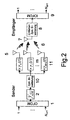
- Fig. 2 the front ends of the transmitter and the receiver, respectively, show the general concept of the method proposed by the invention, with corresponding elements being used for reference numerals corresponding to those of Fig. 1. 1 M s ( t ) Let the time domain signal be after the OFDM modulation in an OFDM modulator 1 and the guard interval insertion.
- the factor introduced by the power distribution section 2 1 M keeps the total transmitted power independent of the number of transmit antennas 5.
- this signal will be in each of the M antenna channels m, 0, ..., M-1 separately multiplied in a multiplier 11 with a signal ⁇ m ( t ).
- the spectra of the channel fading processes ⁇ m , l ( t ) are modified and superimposed according to equation (2).
- This method can be regarded as a type of spread spectrum system, ie a spreading of the transmission signal.
- the fading modification is assigned to the channel and this scheme is considered as a channel transformation, more precisely as a spread of the channel fading process.
- the description emphasizes the standard compatibility of the method according to the invention.
- PSD Power Spectrum Density
- FIG. 3 shows the spectral power density (PSD) of the superposition fading process ⁇ 1 ( t ) when the component processes ⁇ m , l ( t ) of the Jakesian form with f D Max correspond to maximum Doppler spread.
- FIG. 3 shows the spectral power density (PSD) of the superposition fading process ⁇ 1 ( t ) when the component processes ⁇ m , l ( t ) of the Jakesian form with f D Max correspond to maximum Doppler spread.
- FIG. 3 shows the spectral power density (PSD) of the superposition fading process ⁇ 1 ( t ) when the component processes ⁇ m , l ( t ) of the Jakesian form with f
- FIG. 3 (a) shows the spectral power density (PSD) of the channel-specific fading process ⁇ m, l ( t ) and FIG. 3 (b) shows the spectral power density (PSD) of the modified fading process ⁇ 1 ( t ).
- the antenna index m has been omitted for simplicity Since the additional Doppler spread is 20% of subcarrier spacing, ⁇ '(k) is expected to cause serious ICI In contrast, ⁇ "( k ) is during OFDM Symbol periods constant, making the observable ICI dependent only on the channel's own fading processes ⁇ m, l ( t ). Due to the step shape of the Doppler spread signals, this method can be referred to as Discontinuous Doppler Diversity (DDD).
- DDD Discontinuous Doppler Diversity
- the transmitter consists of a source 12 of the signals, a channel encoder 13, an interleaver 14, a modulator 15 and a serial-parallel converter 16.
- the receiver includes a parallel-to-serial converter 17, a demodulator 18, a deinterleaver 19, a Channel decoder 20 and a sink 21 for the signals.
- the information bits coming from the source 12 are coded in the channel coder 13 using a 1/3 rate 1/3 convolutional code or a rate 1/3 turbo code.
- the demodulator 18 provides log likelihood values LL on the assumption that the channel state information CSI is completely known. These LL values are descrambled in de-interleaver 19 and used for soft-decision maximum likelihood (SDML) viiterbi decoding in channel decoder 20.
- SDML soft-decision maximum likelihood
- the model for the channel propagation scenario is a Rayleigh fading model with 2 or 12 taps of equal distance with a 1 dB exponential decay from tap path to tap path and a maximum delay spread of 60 and 176 sample samples, respectively.
- a DDD transmitter with transmit / receive front ends is used, as shown in FIG are shown.
- Table 1 A summary of the main simulation system parameters is shown in Table 1.
- Figures 6-9 show the bit error rate (BER) of the simulation of the method of the invention as compared to a continuous Doppler diversity (DD) method using equation (4).
- BER bit error rate
- DD continuous Doppler diversity
- Figures 6-9 show the bit error rate (BER) of the simulation of the method of the invention as compared to a continuous Doppler diversity (DD) method using equation (4).
- BER bit error rate
- the bit error performance is nearly equal to that of the return antenna system, which means that the diversity gain due to the additional Doppler spread is canceled out by the additional ICI loss.
- the ICI loss continues to increase to maintain balance with the diversity gain, i. the bit error rate (BER) becomes almost equal compared to the return antenna reference system.
- this assumption is modeled by generating independent complex Gaussian distributed zero-mean-space fading coefficients with zero mean zero and a variance of 1/2 per complex dimension, i. the interleaver to deinterleaver simulation chain is considered a replacement IR fading channel.
- Fig. 7 the same 2-tap path Rayleigh fading channel is used in combination with turbo channel coding.
- the performance of convolution and turbo coding is similar.
- the gap for the turbocharged 2-tap IR channel channel scenario is greater than 6 dB because the turbo encoder can further exploit diversity, if available.
- Figure 8 shows the results for a 12-tap Path Rayleigh fading channel and convolutional code.
- This multipath channel provides more frequency diversity than the 2-tap path channel. Therefore, the improvements are only about 2 dB for the convolutionally coded scenario. Further increase of the transmit antenna number shifts the results closer to the performance of the IR channel boundary. The limit is about 1.5 dB for three transmit antennas when using the DDD system.
- FIG. 9 shows the same simulation setup with turbo channel coding.
- the turbo coder Turbocode can exploit the additional diversity of the multipath and DDD compared to the DD system, but is not - as in the DD system - affected by additional interference. However, there is still a 3 dB power loss over the IR curve, which offers the most exploitable diversity. This 3 dB gap could be reduced by increasing the transmit antenna number, while still using the DDD system.
- the DDD system surpasses its Doppler diversity (DD) counterpart without increasing complexity, since additional ICI does not occur and no compensation measures are necessary. Therefore, the higher the initial Doppler spread of the channel, the greater the advantage of the DDD system in terms of ICI.
- the performance of the two systems DD and DDD remains almost the same when ICI is at such a level that it is negligible, i. for low Doppler spreads compared to subcarrier spacing.
- the DDD scheme simplifies the system design because its bit error rate (BER) performance monotonously improves with an increasing number of transmit antennas, whereas in the case of the continuous Doppler diversity technique, an optimum must be found from a certain number of transmit antennas worsening by the vast ICI. An optimization problem for the error rate regarding the number of transmit antennas therefore does not exist for DDD in system design.
- BER bit error rate
- the Doppler spread is changed with a fixed set of transmit antennas.
- the bit error rate (BER) performance is quite similar for all different Doppler spreads.
- Even the initial Doppler spread of 1% is already reliable, to be exploited by the discontinuous Doppler diversity scheme DDD (Discontinuous Doppler Diversity).
- DDD discontinuous Doppler Diversity
- the channel code could not successfully exploit diversity as the potential diversity converges to saturation.
- the lack of diversity gap over the IR (Independent Rayleigh) results could be achieved by using frequency diversity systems, such as, e.g. CDD, be scaled down.
- the invention thus proposes a method for increasing the Doppler spread of fading channels, which provides additional time selectivity and therefore diversity in the time domain.
- the new scheme relies on the use of multiple transmit antennas, where the transmit signal is multiplied by a transmit antenna specific signal, causing the fading processes of the channel to be effectively spread.
- ICI is avoided in OFDM systems due to this increased Doppler spread by keeping the spread signals constant for the duration of an OFDM symbol period and changing the signal only between successive OFDM symbols. This method does not require changes to the receiver, making it standard compatible.
- the present invention is of great interest to the information and communications industry and may, among other things, improve the transmission quality and capacity of existing radio systems as well as future radio systems. Importantly, the method of the invention may also be implemented so that it can be used in existing standards systems without requiring modification of the standards.
- the invention may be advantageous in all systems that have hitherto benefited from a certain degree of temporal selectivity, which benefit has hitherto been of limited use due to the loss of signal energy and the disturbance of neighboring signals.
- This could also include wireless transmission media such as glass fiber, which, based on the additional temporal selectivity, can better utilize their existing dispersion effects to exploit them, for example with suitable channel coding.
- temporal selectivity can also be advantageously integrated into an MC-CDMA system.
Landscapes
- Engineering & Computer Science (AREA)
- Computer Networks & Wireless Communication (AREA)
- Signal Processing (AREA)
- Radio Transmission System (AREA)
- Mobile Radio Communication Systems (AREA)
- Detection And Prevention Of Errors In Transmission (AREA)
Applications Claiming Priority (1)
| Application Number | Priority Date | Filing Date | Title |
|---|---|---|---|
| DE102004034424A DE102004034424A1 (de) | 2004-07-15 | 2004-07-15 | Verfahren zur Übertragung digitaler Nachrichtensignale |
Publications (3)
| Publication Number | Publication Date |
|---|---|
| EP1617569A2 true EP1617569A2 (fr) | 2006-01-18 |
| EP1617569A3 EP1617569A3 (fr) | 2006-05-03 |
| EP1617569B1 EP1617569B1 (fr) | 2007-09-19 |
Family
ID=35134775
Family Applications (1)
| Application Number | Title | Priority Date | Filing Date |
|---|---|---|---|
| EP05014739A Not-in-force EP1617569B1 (fr) | 2004-07-15 | 2005-07-07 | Procédé pour la transmission des signaux d'information numériques avec une pluralité d'antennes |
Country Status (3)
| Country | Link |
|---|---|
| EP (1) | EP1617569B1 (fr) |
| AT (1) | ATE373902T1 (fr) |
| DE (2) | DE102004034424A1 (fr) |
Cited By (1)
| Publication number | Priority date | Publication date | Assignee | Title |
|---|---|---|---|---|
| EP2071758A1 (fr) | 2007-12-11 | 2009-06-17 | Sony Corporation | Appareil et procédé de transmission OFDM, et appareil et procédé de réception OFDM |
Citations (1)
| Publication number | Priority date | Publication date | Assignee | Title |
|---|---|---|---|---|
| EP1289168A1 (fr) * | 2001-08-31 | 2003-03-05 | Deutsches Zentrum für Luft- und Raumfahrt e.V. | Procédé de transmission de données au moyen de signaux radio |
-
2004
- 2004-07-15 DE DE102004034424A patent/DE102004034424A1/de not_active Withdrawn
-
2005
- 2005-07-07 DE DE502005001518T patent/DE502005001518D1/de active Active
- 2005-07-07 AT AT05014739T patent/ATE373902T1/de not_active IP Right Cessation
- 2005-07-07 EP EP05014739A patent/EP1617569B1/fr not_active Not-in-force
Patent Citations (1)
| Publication number | Priority date | Publication date | Assignee | Title |
|---|---|---|---|---|
| EP1289168A1 (fr) * | 2001-08-31 | 2003-03-05 | Deutsches Zentrum für Luft- und Raumfahrt e.V. | Procédé de transmission de données au moyen de signaux radio |
Non-Patent Citations (3)
| Title |
|---|
| DAMMANN A ET AL: "TRANSMIT/RECEIVE-ANTENNA DIVERSITY TECHNIQUES FOR OFDM SYSTEMS" EUROPEAN TRANSACTIONS ON TELECOMMUNICATIONS, WILEY & SONS, CHICHESTER, GB, Bd. 13, Nr. 5, September 2002 (2002-09), Seiten 531-538, XP001133087 ISSN: 1124-318X * |
| RAULEFS R ET AL: "The doppler spread - gaining diversity for future mobile radio systems" GLOBECOM'03. 2003 - IEEE GLOBAL TELECOMMUNICATIONS CONFERENCE. CONFERENCE PROCEEDINGS. SAN FRANCISCO, DEC. 1 - 5, 2003, IEEE GLOBAL TELECOMMUNICATIONS CONFERENCE, NEW YORK, NY : IEEE, US, Bd. VOL. 7 OF 7, 1. Dezember 2003 (2003-12-01), Seiten 1301-1305, XP010677505 ISBN: 0-7803-7974-8 * |
| XIAONNNG PENG ET AL: "Packet transmission in fourth-generation broadband multimedia wireless communication systems" INFORMATION, COMMUNICATIONS AND SIGNAL PROCESSING, 2003 AND FOURTH PACIFIC RIM CONFERENCE ON MULTIMEDIA. PROCEEDINGS OF THE 2003 JOINT CONFERENCE OF THE FOURTH INTERNATIONAL CONFERENCE ON SINGAPORE 15-18 DEC. 2003, PISCATAWAY, NJ, USA,IEEE, Bd. 2, 15. Dezember 2003 (2003-12-15), Seiten 916-920, XP010701273 ISBN: 0-7803-8185-8 * |
Cited By (5)
| Publication number | Priority date | Publication date | Assignee | Title |
|---|---|---|---|---|
| EP2071758A1 (fr) | 2007-12-11 | 2009-06-17 | Sony Corporation | Appareil et procédé de transmission OFDM, et appareil et procédé de réception OFDM |
| EP2071757A1 (fr) | 2007-12-11 | 2009-06-17 | Sony Corporation | Appareil et procédé de transmission, et appareil de réception et procédé |
| EP2234306A1 (fr) | 2007-12-11 | 2010-09-29 | Sony Corporation | Appareil et procédé de transmission OFDM, et appareil et procédé de réception OFDM |
| EA015539B1 (ru) * | 2007-12-11 | 2011-08-30 | Сони Корпорейшн | Устройство и способ передачи и устройство и способ приема |
| EP2387173A2 (fr) | 2007-12-11 | 2011-11-16 | Sony Corporation | Appareil et procédé de transmission OFDM, et appareil et procédé de réception OFDM |
Also Published As
| Publication number | Publication date |
|---|---|
| EP1617569B1 (fr) | 2007-09-19 |
| DE502005001518D1 (de) | 2007-10-31 |
| ATE373902T1 (de) | 2007-10-15 |
| EP1617569A3 (fr) | 2006-05-03 |
| DE102004034424A1 (de) | 2006-02-16 |
Similar Documents
| Publication | Publication Date | Title |
|---|---|---|
| DE60303598T2 (de) | Verfahren und system für multikanalsender und empfänger mit amplituden und phasenkalibrierung | |
| DE69929788T2 (de) | Verfahren und vorrichtung zur diversitätsübertragung | |
| DE60217706T2 (de) | Stfbc-kodierungs-/-dekodierungsvorrichtung und -verfahren in einem ofdm-mobilkommunikationssystem | |
| EP2289213B1 (fr) | Dispositif d'attribution et d'évaluation de symboles de transmission | |
| DE60211705T2 (de) | Verfahren und vorrichtung zum verarbeiten von daten zur übertragung in einem mehrkanaligen kommunikationssystem unter verwendung einer selektiven kanalübertragung | |
| DE602004013462T2 (de) | Broadcast-übertragung mit räumlicher spreizung in einem mehrantennen-kommunikationssystem | |
| DE60035439T2 (de) | Differenzielle raum-zeitblockcodierung | |
| DE10237868B4 (de) | Einrichtung und Verfahren zum Senden und Empfangen von Daten unter Verwendung einer Antennengruppe in einem Mobilkommunikationssystem | |
| DE202008018337U1 (de) | Vorrichtung zum Ermöglichen einer schnellen Decodierung von Übertragungen mit mehreren Codeblöcken | |
| EP2439870B1 (fr) | Procédé de production de signaux d'émission ou de symboles OFDM dans un système de communication et dispositif de système de communication | |
| DE202008018240U1 (de) | Sende-Diversity für Bestätigung und Kategorie 0-Bits in einem drahtlosen Kommunikationssystem | |
| DE202008018251U1 (de) | Sendevorrichtung für CCFI in einem drahtlosen Kommunikationssystem | |
| DE602004006583T2 (de) | Vorrichtung und Verfahren zur Unterdrückung von Interferenzsignalen in einem System mit mehreren Antennen | |
| DE102007051356A1 (de) | Verfahren und Vorrichtung zum Bereitstellen von Zeit-Frequenz-Diversität in drahtlosen OFDM-Kommunikationssystemen | |
| DE60123282T2 (de) | Übertragen eines digitalen signals | |
| DE202004021918U1 (de) | Frequenzselektive Sendesignalgewichtung fürMehrfachantennen-Kommunikationssysteme | |
| DE69830641T2 (de) | Vermittlungssystem mit diversität in einer orthogonalen frequenzmultiplexumgebung, und betriebsverfahren | |
| EP1617569B1 (fr) | Procédé pour la transmission des signaux d'information numériques avec une pluralité d'antennes | |
| EP1223700A1 (fr) | Système et procédé de transmission AMRC à multiporteuses avec mappage adaptatif | |
| DE19543622C2 (de) | Verfahren und Vorrichtung zum bidirektionalen Übertragen von hochratigen Digitalsignalen | |
| DE60209234T2 (de) | Übertragungsverfahren mit verringerter interferenz in ein sttd-schema | |
| EP1605653B1 (fr) | Procédé de transmission de signaux sans fils, employant des mesures d'égalisation | |
| DE10142404B4 (de) | Verfahren zur Funkübertragung von digitalen Nachrichtensignalen | |
| DE102005044963B4 (de) | Verfahren zur Übertragung digitaler Nachrichtensignale | |
| EP2026519A1 (fr) | Prédistorsion pour un encodage de bloc espace-temps |
Legal Events
| Date | Code | Title | Description |
|---|---|---|---|
| PUAI | Public reference made under article 153(3) epc to a published international application that has entered the european phase |
Free format text: ORIGINAL CODE: 0009012 |
|
| AK | Designated contracting states |
Kind code of ref document: A2 Designated state(s): AT BE BG CH CY CZ DE DK EE ES FI FR GB GR HU IE IS IT LI LT LU LV MC NL PL PT RO SE SI SK TR |
|
| AX | Request for extension of the european patent |
Extension state: AL BA HR MK YU |
|
| PUAL | Search report despatched |
Free format text: ORIGINAL CODE: 0009013 |
|
| AK | Designated contracting states |
Kind code of ref document: A3 Designated state(s): AT BE BG CH CY CZ DE DK EE ES FI FR GB GR HU IE IS IT LI LT LU LV MC NL PL PT RO SE SI SK TR |
|
| AX | Request for extension of the european patent |
Extension state: AL BA HR MK YU |
|
| RIC1 | Information provided on ipc code assigned before grant |
Ipc: H04B 7/06 20060101AFI20051101BHEP Ipc: H04L 27/26 20060101ALI20060315BHEP |
|
| RAP1 | Party data changed (applicant data changed or rights of an application transferred) |
Owner name: DEUTSCHES ZENTRUM FUER LUFT- UND RAUMFAHRT E.V. |
|
| 17P | Request for examination filed |
Effective date: 20060811 |
|
| 17Q | First examination report despatched |
Effective date: 20060929 |
|
| AKX | Designation fees paid |
Designated state(s): AT BE BG CH CY CZ DE DK EE ES FI FR GB GR HU IE IS IT LI LT LU LV MC NL PL PT RO SE SI SK TR |
|
| GRAP | Despatch of communication of intention to grant a patent |
Free format text: ORIGINAL CODE: EPIDOSNIGR1 |
|
| GRAS | Grant fee paid |
Free format text: ORIGINAL CODE: EPIDOSNIGR3 |
|
| GRAA | (expected) grant |
Free format text: ORIGINAL CODE: 0009210 |
|
| AK | Designated contracting states |
Kind code of ref document: B1 Designated state(s): AT BE BG CH CY CZ DE DK EE ES FI FR GB GR HU IE IS IT LI LT LU LV MC NL PL PT RO SE SI SK TR |
|
| REG | Reference to a national code |
Ref country code: GB Ref legal event code: FG4D Free format text: NOT ENGLISH |
|
| REG | Reference to a national code |
Ref country code: CH Ref legal event code: EP |
|
| REF | Corresponds to: |
Ref document number: 502005001518 Country of ref document: DE Date of ref document: 20071031 Kind code of ref document: P |
|
| REG | Reference to a national code |
Ref country code: IE Ref legal event code: FG4D Free format text: LANGUAGE OF EP DOCUMENT: GERMAN |
|
| GBT | Gb: translation of ep patent filed (gb section 77(6)(a)/1977) |
Effective date: 20071122 |
|
| PG25 | Lapsed in a contracting state [announced via postgrant information from national office to epo] |
Ref country code: LT Free format text: LAPSE BECAUSE OF FAILURE TO SUBMIT A TRANSLATION OF THE DESCRIPTION OR TO PAY THE FEE WITHIN THE PRESCRIBED TIME-LIMIT Effective date: 20070919 Ref country code: FI Free format text: LAPSE BECAUSE OF FAILURE TO SUBMIT A TRANSLATION OF THE DESCRIPTION OR TO PAY THE FEE WITHIN THE PRESCRIBED TIME-LIMIT Effective date: 20070919 |
|
| PG25 | Lapsed in a contracting state [announced via postgrant information from national office to epo] |
Ref country code: PL Free format text: LAPSE BECAUSE OF FAILURE TO SUBMIT A TRANSLATION OF THE DESCRIPTION OR TO PAY THE FEE WITHIN THE PRESCRIBED TIME-LIMIT Effective date: 20070919 |
|
| NLV1 | Nl: lapsed or annulled due to failure to fulfill the requirements of art. 29p and 29m of the patents act | ||
| PG25 | Lapsed in a contracting state [announced via postgrant information from national office to epo] |
Ref country code: LV Free format text: LAPSE BECAUSE OF FAILURE TO SUBMIT A TRANSLATION OF THE DESCRIPTION OR TO PAY THE FEE WITHIN THE PRESCRIBED TIME-LIMIT Effective date: 20070919 |
|
| PG25 | Lapsed in a contracting state [announced via postgrant information from national office to epo] |
Ref country code: ES Free format text: LAPSE BECAUSE OF FAILURE TO SUBMIT A TRANSLATION OF THE DESCRIPTION OR TO PAY THE FEE WITHIN THE PRESCRIBED TIME-LIMIT Effective date: 20071230 Ref country code: GR Free format text: LAPSE BECAUSE OF FAILURE TO SUBMIT A TRANSLATION OF THE DESCRIPTION OR TO PAY THE FEE WITHIN THE PRESCRIBED TIME-LIMIT Effective date: 20071220 Ref country code: NL Free format text: LAPSE BECAUSE OF FAILURE TO SUBMIT A TRANSLATION OF THE DESCRIPTION OR TO PAY THE FEE WITHIN THE PRESCRIBED TIME-LIMIT Effective date: 20070919 |
|
| REG | Reference to a national code |
Ref country code: IE Ref legal event code: FD4D |
|
| ET | Fr: translation filed | ||
| PG25 | Lapsed in a contracting state [announced via postgrant information from national office to epo] |
Ref country code: PT Free format text: LAPSE BECAUSE OF FAILURE TO SUBMIT A TRANSLATION OF THE DESCRIPTION OR TO PAY THE FEE WITHIN THE PRESCRIBED TIME-LIMIT Effective date: 20080219 Ref country code: SK Free format text: LAPSE BECAUSE OF FAILURE TO SUBMIT A TRANSLATION OF THE DESCRIPTION OR TO PAY THE FEE WITHIN THE PRESCRIBED TIME-LIMIT Effective date: 20070919 Ref country code: IS Free format text: LAPSE BECAUSE OF FAILURE TO SUBMIT A TRANSLATION OF THE DESCRIPTION OR TO PAY THE FEE WITHIN THE PRESCRIBED TIME-LIMIT Effective date: 20080119 Ref country code: CZ Free format text: LAPSE BECAUSE OF FAILURE TO SUBMIT A TRANSLATION OF THE DESCRIPTION OR TO PAY THE FEE WITHIN THE PRESCRIBED TIME-LIMIT Effective date: 20070919 |
|
| PG25 | Lapsed in a contracting state [announced via postgrant information from national office to epo] |
Ref country code: RO Free format text: LAPSE BECAUSE OF FAILURE TO SUBMIT A TRANSLATION OF THE DESCRIPTION OR TO PAY THE FEE WITHIN THE PRESCRIBED TIME-LIMIT Effective date: 20070919 Ref country code: SE Free format text: LAPSE BECAUSE OF FAILURE TO SUBMIT A TRANSLATION OF THE DESCRIPTION OR TO PAY THE FEE WITHIN THE PRESCRIBED TIME-LIMIT Effective date: 20071219 |
|
| PLBE | No opposition filed within time limit |
Free format text: ORIGINAL CODE: 0009261 |
|
| STAA | Information on the status of an ep patent application or granted ep patent |
Free format text: STATUS: NO OPPOSITION FILED WITHIN TIME LIMIT |
|
| PG25 | Lapsed in a contracting state [announced via postgrant information from national office to epo] |
Ref country code: DK Free format text: LAPSE BECAUSE OF FAILURE TO SUBMIT A TRANSLATION OF THE DESCRIPTION OR TO PAY THE FEE WITHIN THE PRESCRIBED TIME-LIMIT Effective date: 20070919 |
|
| 26N | No opposition filed |
Effective date: 20080620 |
|
| PG25 | Lapsed in a contracting state [announced via postgrant information from national office to epo] |
Ref country code: IE Free format text: LAPSE BECAUSE OF FAILURE TO SUBMIT A TRANSLATION OF THE DESCRIPTION OR TO PAY THE FEE WITHIN THE PRESCRIBED TIME-LIMIT Effective date: 20070919 |
|
| PG25 | Lapsed in a contracting state [announced via postgrant information from national office to epo] |
Ref country code: MC Free format text: LAPSE BECAUSE OF NON-PAYMENT OF DUE FEES Effective date: 20080731 |
|
| PG25 | Lapsed in a contracting state [announced via postgrant information from national office to epo] |
Ref country code: EE Free format text: LAPSE BECAUSE OF FAILURE TO SUBMIT A TRANSLATION OF THE DESCRIPTION OR TO PAY THE FEE WITHIN THE PRESCRIBED TIME-LIMIT Effective date: 20070919 |
|
| PG25 | Lapsed in a contracting state [announced via postgrant information from national office to epo] |
Ref country code: SI Free format text: LAPSE BECAUSE OF FAILURE TO SUBMIT A TRANSLATION OF THE DESCRIPTION OR TO PAY THE FEE WITHIN THE PRESCRIBED TIME-LIMIT Effective date: 20070919 |
|
| PG25 | Lapsed in a contracting state [announced via postgrant information from national office to epo] |
Ref country code: CY Free format text: LAPSE BECAUSE OF FAILURE TO SUBMIT A TRANSLATION OF THE DESCRIPTION OR TO PAY THE FEE WITHIN THE PRESCRIBED TIME-LIMIT Effective date: 20070919 |
|
| PG25 | Lapsed in a contracting state [announced via postgrant information from national office to epo] |
Ref country code: BG Free format text: LAPSE BECAUSE OF FAILURE TO SUBMIT A TRANSLATION OF THE DESCRIPTION OR TO PAY THE FEE WITHIN THE PRESCRIBED TIME-LIMIT Effective date: 20071219 |
|
| PG25 | Lapsed in a contracting state [announced via postgrant information from national office to epo] |
Ref country code: AT Free format text: LAPSE BECAUSE OF NON-PAYMENT OF DUE FEES Effective date: 20080707 |
|
| REG | Reference to a national code |
Ref country code: CH Ref legal event code: PL |
|
| PG25 | Lapsed in a contracting state [announced via postgrant information from national office to epo] |
Ref country code: CH Free format text: LAPSE BECAUSE OF NON-PAYMENT OF DUE FEES Effective date: 20090731 Ref country code: LI Free format text: LAPSE BECAUSE OF NON-PAYMENT OF DUE FEES Effective date: 20090731 |
|
| PG25 | Lapsed in a contracting state [announced via postgrant information from national office to epo] |
Ref country code: BE Free format text: LAPSE BECAUSE OF NON-PAYMENT OF DUE FEES Effective date: 20080731 Ref country code: HU Free format text: LAPSE BECAUSE OF FAILURE TO SUBMIT A TRANSLATION OF THE DESCRIPTION OR TO PAY THE FEE WITHIN THE PRESCRIBED TIME-LIMIT Effective date: 20080320 Ref country code: LU Free format text: LAPSE BECAUSE OF NON-PAYMENT OF DUE FEES Effective date: 20080707 |
|
| PG25 | Lapsed in a contracting state [announced via postgrant information from national office to epo] |
Ref country code: TR Free format text: LAPSE BECAUSE OF FAILURE TO SUBMIT A TRANSLATION OF THE DESCRIPTION OR TO PAY THE FEE WITHIN THE PRESCRIBED TIME-LIMIT Effective date: 20070919 |
|
| PG25 | Lapsed in a contracting state [announced via postgrant information from national office to epo] |
Ref country code: IT Free format text: LAPSE BECAUSE OF NON-PAYMENT OF DUE FEES Effective date: 20080731 |
|
| REG | Reference to a national code |
Ref country code: DE Ref legal event code: R084 Ref document number: 502005001518 Country of ref document: DE |
|
| REG | Reference to a national code |
Ref country code: DE Ref legal event code: R084 Ref document number: 502005001518 Country of ref document: DE Effective date: 20140404 |
|
| REG | Reference to a national code |
Ref country code: FR Ref legal event code: PLFP Year of fee payment: 11 |
|
| REG | Reference to a national code |
Ref country code: FR Ref legal event code: PLFP Year of fee payment: 12 |
|
| REG | Reference to a national code |
Ref country code: FR Ref legal event code: PLFP Year of fee payment: 13 |
|
| REG | Reference to a national code |
Ref country code: FR Ref legal event code: PLFP Year of fee payment: 14 |
|
| PGFP | Annual fee paid to national office [announced via postgrant information from national office to epo] |
Ref country code: FR Payment date: 20190621 Year of fee payment: 15 |
|
| PGFP | Annual fee paid to national office [announced via postgrant information from national office to epo] |
Ref country code: GB Payment date: 20190626 Year of fee payment: 15 Ref country code: DE Payment date: 20190617 Year of fee payment: 15 |
|
| REG | Reference to a national code |
Ref country code: DE Ref legal event code: R119 Ref document number: 502005001518 Country of ref document: DE |
|
| GBPC | Gb: european patent ceased through non-payment of renewal fee |
Effective date: 20200707 |
|
| PG25 | Lapsed in a contracting state [announced via postgrant information from national office to epo] |
Ref country code: FR Free format text: LAPSE BECAUSE OF NON-PAYMENT OF DUE FEES Effective date: 20200731 Ref country code: GB Free format text: LAPSE BECAUSE OF NON-PAYMENT OF DUE FEES Effective date: 20200707 |
|
| PG25 | Lapsed in a contracting state [announced via postgrant information from national office to epo] |
Ref country code: DE Free format text: LAPSE BECAUSE OF NON-PAYMENT OF DUE FEES Effective date: 20210202 |