EP1617569A2 - Method for transmission of digital information signals with a plurality of antennas - Google Patents
Method for transmission of digital information signals with a plurality of antennas Download PDFInfo
- Publication number
- EP1617569A2 EP1617569A2 EP05014739A EP05014739A EP1617569A2 EP 1617569 A2 EP1617569 A2 EP 1617569A2 EP 05014739 A EP05014739 A EP 05014739A EP 05014739 A EP05014739 A EP 05014739A EP 1617569 A2 EP1617569 A2 EP 1617569A2
- Authority
- EP
- European Patent Office
- Prior art keywords
- transmission
- receiver
- signals
- time
- signal
- Prior art date
- Legal status (The legal status is an assumption and is not a legal conclusion. Google has not performed a legal analysis and makes no representation as to the accuracy of the status listed.)
- Granted
Links
- 238000000034 method Methods 0.000 title claims abstract description 85
- 230000005540 biological transmission Effects 0.000 title claims abstract description 78
- 238000012937 correction Methods 0.000 claims abstract description 3
- 125000004122 cyclic group Chemical group 0.000 claims description 16
- 238000004891 communication Methods 0.000 claims description 14
- 230000004048 modification Effects 0.000 claims description 5
- 238000012986 modification Methods 0.000 claims description 5
- 238000003491 array Methods 0.000 claims description 4
- 230000001413 cellular effect Effects 0.000 claims description 3
- 238000006073 displacement reaction Methods 0.000 claims description 2
- 238000012545 processing Methods 0.000 claims description 2
- 230000008054 signal transmission Effects 0.000 claims 1
- 238000012876 topography Methods 0.000 claims 1
- 238000001514 detection method Methods 0.000 abstract description 2
- 238000005562 fading Methods 0.000 description 38
- 238000004088 simulation Methods 0.000 description 15
- 230000002123 temporal effect Effects 0.000 description 13
- 230000008569 process Effects 0.000 description 10
- 238000001228 spectrum Methods 0.000 description 9
- 238000010586 diagram Methods 0.000 description 7
- 230000003595 spectral effect Effects 0.000 description 7
- 238000011161 development Methods 0.000 description 5
- 230000018109 developmental process Effects 0.000 description 5
- 230000000694 effects Effects 0.000 description 5
- 239000000969 carrier Substances 0.000 description 3
- 230000001934 delay Effects 0.000 description 3
- 230000001419 dependent effect Effects 0.000 description 3
- 230000006872 improvement Effects 0.000 description 3
- 230000008901 benefit Effects 0.000 description 2
- 238000013461 design Methods 0.000 description 2
- 238000010295 mobile communication Methods 0.000 description 2
- 238000005457 optimization Methods 0.000 description 2
- 230000009467 reduction Effects 0.000 description 2
- 230000004044 response Effects 0.000 description 2
- 230000009466 transformation Effects 0.000 description 2
- 239000004606 Fillers/Extenders Substances 0.000 description 1
- 238000007476 Maximum Likelihood Methods 0.000 description 1
- 230000003044 adaptive effect Effects 0.000 description 1
- 239000000654 additive Substances 0.000 description 1
- 230000000996 additive effect Effects 0.000 description 1
- 238000013459 approach Methods 0.000 description 1
- 230000008859 change Effects 0.000 description 1
- 238000006243 chemical reaction Methods 0.000 description 1
- 238000000750 constant-initial-state spectroscopy Methods 0.000 description 1
- 239000000470 constituent Substances 0.000 description 1
- 238000010276 construction Methods 0.000 description 1
- 238000013016 damping Methods 0.000 description 1
- 230000003111 delayed effect Effects 0.000 description 1
- 230000001066 destructive effect Effects 0.000 description 1
- 239000006185 dispersion Substances 0.000 description 1
- 239000003365 glass fiber Substances 0.000 description 1
- 238000003780 insertion Methods 0.000 description 1
- 230000037431 insertion Effects 0.000 description 1
- 230000037361 pathway Effects 0.000 description 1
- 230000002441 reversible effect Effects 0.000 description 1
- 230000007480 spreading Effects 0.000 description 1
- 238000012546 transfer Methods 0.000 description 1
Images


Classifications
-
- H—ELECTRICITY
- H04—ELECTRIC COMMUNICATION TECHNIQUE
- H04B—TRANSMISSION
- H04B7/00—Radio transmission systems, i.e. using radiation field
- H04B7/02—Diversity systems; Multi-antenna system, i.e. transmission or reception using multiple antennas
- H04B7/12—Frequency diversity
-
- H—ELECTRICITY
- H04—ELECTRIC COMMUNICATION TECHNIQUE
- H04L—TRANSMISSION OF DIGITAL INFORMATION, e.g. TELEGRAPHIC COMMUNICATION
- H04L1/00—Arrangements for detecting or preventing errors in the information received
- H04L1/004—Arrangements for detecting or preventing errors in the information received by using forward error control
- H04L1/0056—Systems characterized by the type of code used
- H04L1/0071—Use of interleaving
-
- H—ELECTRICITY
- H04—ELECTRIC COMMUNICATION TECHNIQUE
- H04L—TRANSMISSION OF DIGITAL INFORMATION, e.g. TELEGRAPHIC COMMUNICATION
- H04L1/00—Arrangements for detecting or preventing errors in the information received
- H04L1/02—Arrangements for detecting or preventing errors in the information received by diversity reception
- H04L1/06—Arrangements for detecting or preventing errors in the information received by diversity reception using space diversity
- H04L1/0618—Space-time coding
-
- H—ELECTRICITY
- H04—ELECTRIC COMMUNICATION TECHNIQUE
- H04L—TRANSMISSION OF DIGITAL INFORMATION, e.g. TELEGRAPHIC COMMUNICATION
- H04L1/00—Arrangements for detecting or preventing errors in the information received
- H04L1/12—Arrangements for detecting or preventing errors in the information received by using return channel
- H04L1/16—Arrangements for detecting or preventing errors in the information received by using return channel in which the return channel carries supervisory signals, e.g. repetition request signals
- H04L1/18—Automatic repetition systems, e.g. Van Duuren systems
- H04L1/1812—Hybrid protocols; Hybrid automatic repeat request [HARQ]
-
- H—ELECTRICITY
- H04—ELECTRIC COMMUNICATION TECHNIQUE
- H04L—TRANSMISSION OF DIGITAL INFORMATION, e.g. TELEGRAPHIC COMMUNICATION
- H04L27/00—Modulated-carrier systems
- H04L27/26—Systems using multi-frequency codes
- H04L27/2601—Multicarrier modulation systems
- H04L27/2602—Signal structure
Abstract
Description
Die Erfindung betrifft ein Verfahren zur Übertragung digitaler Nachrichtensignale von einem mehrere Signalaussendeeinrichtungen oder Signalaussendeeinrichtungsgruppen, wie z.B. Antennen oder Antennengruppen, aufweisenden Sender zu einem Empfänger eines Übertragungssystems, z.B. eines Funkübertragungssystems, über ein Übertragungsmedium, das am Empfänger zu einer Varianz der Leistung der Signale in der Zeit und damit zu nicht fehlerfreier Übertragung führen kann, unter Verwendung von Diversitätsmaßnahmen im Frequenz- und/oder Zeitbereich.The invention relates to a method of transmitting digital message signals from a plurality of signal emitters or signal emitter groups, such as e.g. Antennas or antenna arrays comprising transmitters to a receiver of a transmission system, e.g. a radio transmission system, via a transmission medium, which at the receiver can lead to a variance of the power of the signals in time and thus to not faultless transmission, using diversity measures in the frequency and / or time domain.
Die Mehrwegeausbreitung des Signals im Übertragungskanal von Funksystemen verursacht konstruktive und destruktive Überlagerungen des Signals an der Empfangsantenne. Kritisch ist vor allem der daraus resultierende Signalschwund, der dazu führen kann, dass die Qualität der Funkverbindung sehr schlecht wird und die Verbindung nicht mehr aufrecht erhalten werden kann.The multipath propagation of the signal in the transmission channel of radio systems causes constructive and destructive interference of the signal at the receiving antenna. Above all, the resulting signal loss is critical, which can lead to the quality of the radio connection becoming very poor and the connection can no longer be maintained.
Es sind mehrere Verfahren bekannt, die eingesetzt werden können, um dem Signalschwund entgegenzuwirken.Several methods are known that can be used to counteract the signal fading.
Beispielsweise aus dem Buch von J. G. Proakis: "Digital Communications", New York, McGraw-Hill, 1995 ist die Kanalcodierung bekannt, die auf Kosten von Redundanz im Datenstrom Übertragungsfehler in begrenztem Maße korrigieren kann. Eine solche Kanalcodierung verringert die spektrale Effizienz des Systems, da Redundanz in den Datenstrom eingefügt werden muss. Bei heutigen Rundfunksystemen wie DAB und DVB, aber auch bei Mobilfunksystemen wie z.B. GSM und UMTS liegen diese Verluste in der Größenordung von 50%.For example, in the book by JG Proakis, "Digital Communications," New York, McGraw-Hill, 1995, channel coding is known which can to a limited extent correct transmission errors at the expense of redundancy in the data stream. Such channel coding reduces the spectral efficiency of the system because redundancy must be introduced into the data stream. In today's broadcasting systems such as DAB and DVB, but also in mobile systems such as GSM and UMTS, these losses are in the order of 50%.
Eine andere Methode, um einem Signalschwund entgegenzuwirken, ist die aus dem Buch von R. van Nee und R. Prasad: "OFDM for Wireless Multimedia Communications", Artech House Publishers, 2000 bekannte Leistungsregelung, die bei starken Signaldämpfungen die Sendeleistung anhebt, um die Verbindung aufrecht zu erhalten. Eine derartige Leistungsregelung erhöht die Interferenz in einem Funksystem, da dadurch andere Teilnehmer stärker gestört werden können. Ferner widerstrebt dieser Ansatz dem Ziel, den Durchsatz an Daten zu optimieren, da verstärkt Sendeleistung in ungünstigen Übertragungskanälen verschwendet wird, die dann aber nicht mehr für die guten Übertragungskanäle zur Verfügung steht.Another method of counteracting signal fading is the power control known from the book by R. van Nee and R. Prasad, "OFDM for Wireless Multimedia Communications," Artech House Publishers, 2000, which increases transmit power at high signal attenuations Maintain connection. Such a power control increases the interference in a radio system, as it can disrupt other participants more. Furthermore, this approach is reluctant to the goal of optimizing the throughput of data, as more transmission power is wasted in unfavorable transmission channels, which is then no longer available for the good transmission channels.
In dem bereits erwähnten Buch von J. G. Proakis und aus dem Artikel von S. Kaiser: "Spatial transmit diversity techniques for broadband OFDM systems" in Proc. IEEE Global Telecommun. Conf. (GLOBECOM 2000), San Francisco, USA, Seiten 1824-1828, Nov./Dec. 2000 sind Diversitätstechniken beschrieben, bei denen mehrere Sende- und/oder Empfangsantennen eingesetzt werden, wodurch mehrere unabhängig voneinander gestörte Signale am/im Empfänger überlagert werden und die Datendetektion zuverlässiger wird. Hierbei gibt es Diversitätstechniken, die sowohl die Zeit- als auch die Frequenzrichtung ausnutzen. Im Zeitbereich arbeiten diese Techniken bislang mit einem einhergehenden Verlust von Signalenergie und einer Störung der Nachbarsignale.In the already mentioned book by J. G. Proakis and from the article by S. Kaiser: "Spatial transmit diversity techniques for broadband OFDM systems" in Proc. IEEE Global Telecommun. Conf. (GLOBECOM 2000), San Francisco, USA, pages 1824-1828, Nov./Dec. In 2000, diversity techniques are described in which multiple transmit and / or receive antennas are used, thereby superimposing multiple independently disturbed signals on / in the receiver and making data detection more reliable. There are diversity techniques that exploit both the time and frequency directions. In the time domain, these techniques have so far worked with a concomitant loss of signal energy and interference with neighboring signals.
Aus den Artikeln von V. Tarokh, N. Seshadri und A. R. Calderbank: "Space-Time Codes for High Data Rate Wireless Communication: Performance Criterion and Code Construction" in IEEE Transactions on Information Theory, Vol. 44, No. 2, Seiten 744-764, März 1998 und S. M. Alamouti: "A simple transmit diversity technique for wireless communications" in IEEE Journal on Selected Areas in Communications, Vol. 16, No. 8, Seiten 1451-1458, Oktober 1998 ist das sogenannte Space-Time-Coding bekannt, das zusätzlich Redundanz in "Raumrichtung" einfügt. Dabei werden über mehrere Sendeantennen gleichzeitig verschiedene codierte Signale abgestrahlt, die über eine oder mehrere Empfangsantennen empfangen werden. Bei der Verwendung von Space-Time-Coding ist empfangsseitig ein geeigneter Decoder zur Verfügung zu stellen.From the articles by V. Tarokh, N. Seshadri and AR Calderbank: "Space-Time Codes for High-Rate Wireless Communication: Performance Criterion and Code Construction" in IEEE Transactions on Information Theory, Vol. 44, no. 2, pages 744-764, March 1998 and SM Alamouti: "A simple transmit diversity technique for wireless communications" in IEEE Journal on Selected Areas in Communications, Vol. 16, no. 8, pages 1451-1458, October 1998, the so-called space-time coding is known, which additionally introduces redundancy in "spatial direction". In this case, different coded signals are simultaneously emitted via several transmitting antennas, which are received via one or more receiving antennas. When using space-time coding, a suitable decoder must be provided at the receiving end.
In den Artikeln von L. C. Godara: "Applications of Antenna Arrays to Mobile Communications, Part I: Performance Improvement, Feasibility, and System Considerations" in Proceedings of the IEEE, Vol. 85, No.7, Seiten 1031-1060 und L. C. Godara: "Applications of Antenna Arrays to Mobile Communications, Part II: Beam-Forming and Direction-of-Arrival Considerations" in Proceedings of the IEEE, Vol. 85, No.8, Seiten 1195-1245 sind intelligente Antennen beschrieben, die auf "intelligente" Art mittels eines adaptiven Antennenprozessors mehrere Signale in Empfangs- oder Senderichtung mit verschiedenen Antennenelementen kombinieren.In the articles of LC Godara: "Applications of Antenna Arrays to Mobile Communications, Part I: Performance Improvement, Feasibility, and System Considerations" in Proceedings of the IEEE, Vol. 85, No.7, pages 1031-1060 and LC Godara: "Applications of Antenna Arrays to Mobile Communications, Part II: Beam-Forming and Direction-of-Arrival Considerations" in Proceedings of the IEEE, Vol. 85, No.8, pages 1195-1245, describes smart antennas that are based on "intelligent "Art using an adaptive antenna processor combine several signals in the receive or transmit direction with different antenna elements.
Die Sendesignale werden mittels Antennenkeulen in Richtung der besten Signalwege für den Empfänger ausgesendet. Die zur Verfügung stehende Sendeleistung wird optimal gebündelt und Interferenz im zellularen Funksystem minimiert. Die Empfangssignale werden durch das Ausrichten der Keulen einer intelligenten Antenne am Empfänger optimal empfangen und Störsignale werden unterdrückt. Da sich bei intelligenten Antennen das Signal einer Sendekeule im Kanal immer noch dispersiv ausbreitet, kommt es dennoch zu Signaldämpfungen, die mit einer der anderen zuvor erwähnten Methoden behoben werden müssen, wobei auch deren Nachteile nicht vermieden werden können.The transmission signals are transmitted by means of antenna lobes in the direction of the best signal paths for the receiver. The available transmission power is optimally bundled and interference in the cellular radio system is minimized. The received signals are optimally received by aligning the lobes of an intelligent antenna at the receiver and interference signals are suppressed. As with intelligent antennas, the signal of a transmitting lobe in the channel always still spreads dispersive, yet it comes to signal attenuation, which must be remedied with one of the other methods mentioned above, and their disadvantages can not be avoided.
Der Erfindung liegt die Aufgabe zu Grunde, die negativen Auswirkungen des Signalschwunds weiter zu reduzieren und dabei die erforderliche Sendeleistung und die dadurch verursachte Interferenz im Übertragungssystem zu verringern.The invention is based on the object to further reduce the negative effects of signal fading while reducing the required transmission power and the interference caused thereby in the transmission system.
Gemäß der Erfindung, die sich auf ein Verfahren zur Übertragung digitaler Nachrichtensignale der eingangs genannten Art bezieht, wird diese Aufgabe dadurch gelöst, dass am Sender die auszusendenden Signale für die verschiedenen Signalaussendeeinrichtungen bzw. Signalaussendeeinrichtungsgruppen durch zeitdispersive diskontinuierliche Verschiebung verschieden modifiziert und somit zeitlich diskontinuierlich versetzt ausgesendet werden, so dass der Empfänger in der Lage ist, das Signal auf Grund der zusätzlichen Diversität korrekt zu detektieren.According to the invention, which relates to a method for transmitting digital communication signals of the type mentioned above, this object is achieved in that differently modifies the signals to be transmitted for the various signal emitter or Signalaussendeeinrichtungsgruppen by time-dispersive discontinuous shift and thus emitted discontinuously offset in time so that the receiver is able to correctly detect the signal due to the additional diversity.
In Funksystemen wird durch das Verfahren nach der Erfindung am Sender durch zeitdispersive diskontinuierliche Verschiebung das Sendesignal an mehreren Antennen oder Antennengruppen verschieden modifiziert, so dass der Empfänger in der Lage ist, das Signal aufgrund der zusätzlichen Diversität korrekt zu detektieren. Die zeitdispersive diskontinuierliche Veränderung des Sendesignals wird verlustfrei und somit ohne Energieverlust des Sendesignals und ohne Störung der Nachbarsendesignale durchgeführt. Das Verfahren nach der Erfindung reduziert die negativen Auswirkungen des Signalschwunds im Mehrwegeausbreitungskanals; somit reduziert es die erforderliche Sendeleistung und die dadurch verursachte Interferenz im Funksystem.In radio systems, the transmission signal is modified differently at several antennas or antenna groups by the method according to the invention at the transmitter by time-dispersive discontinuous displacement, so that the receiver is able to correctly detect the signal due to the additional diversity. The time-dispersive discontinuous change of the transmission signal is lossless and thus performed without loss of energy of the transmission signal and without disturbing the neighboring transmission signals. The method of the invention reduces the negative effects of signal fading in the multipath propagation channel; thus it reduces the required transmit power and the resulting interference in the radio system.
Ein wesentliches Merkmal der Erfindung besteht darin, dass die Signale an den verschiedenen Antennen bzw. Signalaussendeeinrichtungen des Senders zeitlich diskontinuierlich versetzt gesendet werden. Dies kann als eine zeitliche Spreizung des Sendesignals angesehen werden. Eine Spreizung im Frequenzbereich erhöht die Zeitselektivität im Spektrum des empfangenen Signals. Eine deterministische Zeitselektivität des Spektrums kann z.B. im Falle eines Schwundkanals ohne zeitliche Selektivität diese künstlich erzeugen, um Fälle zu vermeiden, in denen sich das gesamte Spektrum in einem tiefen Schwund befindet und es zu erheblichen Störungen im Empfänger kommt, bis hin zum gesamten Systemausfall. Dies wird mit dem neuen Verfahren nach der Erfindung durch die künstliche Selektivität erreicht und in vorteilhafter Weise durch eine Kombination mit einer geeigneten Kanalcodierung noch verbessert.An essential feature of the invention is that the signals at the various antennas or signal emitting devices of the transmitter are transmitted discontinuously offset in time. This can be regarded as a temporal spread of the transmission signal. A spread in the frequency domain increases the time selectivity in the spectrum of the received signal. A deterministic time selectivity of the spectrum may e.g. in the case of a fading channel with no temporal selectivity, artificially generate them to avoid cases in which the entire spectrum is in a deep fading and there are significant disturbances in the receiver, up to the total system failure. This is achieved with the new method according to the invention by the artificial selectivity and improved in an advantageous manner by a combination with a suitable channel coding.
Ist die zeitliche Varianz des Übertragungskanals langsam, z.B. in kleinen Funkzellen wie im Indoor-Bereich, so kann das Empfangssignal längere Zeit einem starken Signalschwund unterliegen und die Verbindung abbrechen. Wird eine künstliche Zeitvarianz herbeigeführt, so ist der zeitliche Signalschwund relativ kurz und die auftretenden Übertragungsfehler können in geeigneter Weise z.B. von einer Kanalcodierung korrigiert werden. Die Effizienz kann durch das Verwürfeln der Daten im Sender mit einem Interleaver verbessert werden. Bei einer OFDM-Übertragung kann dies ein Zeit- und Frequenzinterleaving sein. Der Empfänger stellt hierbei die entsprechenden Deinterleaver zur Verfügung.If the temporal variance of the transmission channel is slow, for example in small radio cells as in the indoor area, the received signal can be subject to a long time a strong signal fading and terminate the connection. If an artificial time variance is brought about, then the temporal signal fading is relatively short and the occurring transmission errors can be corrected in a suitable manner, for example by a channel coding. The efficiency can be improved by scrambling the data in the transmitter with an interleaver. In OFDM transmission, this may be a time and frequency interleaving. The recipient provides the corresponding deinterleaver.
Die diskontinuierliche zeitliche Selektivität erlaubt es, die Wahl des Diversitätsgrades beispielsweise bei Mehrträgersystemen nur noch auf Grund der maximal beherrschbaren verlustfreien Zeitselektivität durch das erfindungsgemäße Verfahren im existierenden physikalischen Übertragungssystem zu maximieren. Das Verfahren nach der Erfindung setzt die verwendbare Diversität auf einen maximalen Grad ohne den Verlust von Energie an Nachbarträger bzw. ohne die Störung von Nachbarträgern im System. Durch das verlustfreie Erhöhen der Diversität im System kann die spektrale Effizienz durch das Maximieren der Anzahl von Trägern innerhalb einer gegebenen Bandbreite optimiert werden. Durch das deterministische Einsetzen der diskontinuierlichen zeitlichen Selektivität kann der Effekt verlustfrei ausgenutzt werden.The discontinuous temporal selectivity makes it possible to maximize the choice of the degree of diversity, for example in multi-carrier systems only because of the maximum controllable loss-free time selectivity by the inventive method in the existing physical transmission system. The method according to the invention sets the usable diversity to a maximum degree without the loss of energy to neighboring carriers or without interference from neighboring carriers in the system. By losslessly increasing diversity in the system, spectral efficiency can be optimized by maximizing the number of carriers within a given bandwidth. Due to the deterministic use of the discontinuous temporal selectivity, the effect can be exploited without loss.
Die diskontinuierliche zeitliche Selektivität ist nicht an eine drahtlose Übertragung gebunden, sondern ist in jedem Übertragungsmedium anwendbar, das am Empfänger an einer Varianz der Leistung des Signals in der Zeit und damit an einer nicht fehlerfreien Übertragung leidet. Dies kann durch Schwundkanäle oder beispielsweise auch durch Übertragungsmedien verursacht werden, die sich in Abhängigkeit von der Wellenlänge durch unterschiedliche Dämpfungseigenschaften auszeichnen.The discontinuous temporal selectivity is not tied to wireless transmission but is applicable in any transmission medium that suffers from variance in the power of the signal over time at the receiver and hence in a non-error-free transmission. This can be caused by fading channels or, for example, also by transmission media, which are distinguished by different damping properties as a function of the wavelength.
In den Artikeln von A. Dammann, S. Kaiser: "Performance of low complex antenna diversity techniques for mobile OFDM systems" in Proceedings 3rd International Workshop on Multi-Carrier Spread-Spectrum & Related Topics (MC-SS'2001), Oberpfaffenhofen, Germany, September 2001, Seiten 53-64, ISBN 0-7923-7653-6 und von A. Dammann, S. Kaiser: "Transmit/receive antenna diversity techniques for OFDM systems" in European Transactions on Telecommunications, Vol. 13, No. 5, Seiten 531-538, September-Oktober 2002 ist das sogenannte Cyclic-Delay-Diversity-Verfahren beschrieben, welches die Diversität im Frquenzbereich eines OFDM-Systems maximiert, ohne zusätzliche Intersymbolinterferenzen (ISI) hervorzurufen. Die diskontinuierliche zeitliche Selektivität kann in vorteilhafter Weise mit dem Cyclic-Delay-Diversity(CDD)-Verfahren verknüpft werden. Beide Techniken zusammen erschließen mit der räumlichen Komponente den potentiellen Diversitätsraum (Zeit- und Frequenzbereich) komplett. Durch das Verknüpfen beider Techniken kann man Übertragungssysteme mit einer zufälligen Dämpfungskomponente durch künstliche Selektivität in Frequenz und Zeit optimieren.In the articles by A. Dammann, S. Kaiser: "Performance of low complex antenna diversity techniques for mobile OFDM systems" in
Das erfindungsgemäße Verfahren, das mit diskontinuierlicher zeitlicher Selektivität arbeitet, kann des weiteren vorteilhaft in Funkübertragungssystemen mit intelligenten Antennengruppen eingesetzt werden. Intelligente Antennengruppen formen den Sendestrahl, so dass Interferenz im Übertragungssystem vermieden werden kann. Jedoch wird durch die Reduzierung der räumlichen Sendekeulen die Zeit- und Frequenzvarianz vermieden. Hierdurch entsteht eine Reduzierung der Selektivität im Übertragungssystem, wodurch Fehler bis zu einem totalen Abbruch der Funkverbindung entstehen können. Die diskontinuierliche zeitliche Selektivität nach der Erfindung erlaubt es nun, diese Reduzierung verlustfrei durch die Modifikation des Sendesignals zu kompensieren und somit eine verlustfreie Übertragung zu gewähren.The method according to the invention, which operates with discontinuous temporal selectivity, can furthermore advantageously be used in radio transmission systems with intelligent antenna groups. Intelligent antenna groups form the transmission beam, so that interference in the transmission system can be avoided. However, reducing the spatial transmission lobes avoids the time and frequency variance. This results in a reduction of the selectivity in the transmission system, which can cause errors up to a total termination of the radio connection. The discontinuous temporal selectivity according to the invention now makes it possible to compensate for this reduction lossless by the modification of the transmission signal and thus to provide a lossless transmission.
Eine vorteilhafte Weiterbildung der Erfindung ist somit durch die Verknüpfung der erwähnten Merkmale zusätzlich mit dem Cyclic-Delay-Diversity(CDD)-Verfahren gegeben.An advantageous development of the invention is thus given by the combination of the mentioned features in addition to the cyclic delay diversity (CDD) method.
Hierbei wird der vorhandene Übertragungsraum im Zeit- und Frequenzbereich maximal ausgenutzt, was in zweckmäßiger Weise noch mit der Optimierung im Raum durch intelligente Antennengruppen verbunden werden kann, die gezielt den Empfänger durch die topographischen Gegebenheiten des Kanals ansprechen. Die entstehende künstliche Selektivität vermeidet eine fehlerhafte Kommunikation zwischen Sender und Empfänger, wobei diese Sicherheit durch die Verbindung mit einer geeigneten Kanalcodierung noch gesteigert werden kann.Here, the existing transmission space in the time and frequency range is utilized to the maximum, which can be connected in an expedient manner with the optimization in space by intelligent antenna groups that specifically address the receiver by the topographical conditions of the channel. The resulting artificial selectivity avoids faulty communication between transmitter and receiver, this security can be increased by the connection with a suitable channel coding yet.
Eine andere vorteilhafte Weiterbildung der Erfindung besteht darin, die einzelnen Sendekeulen mit Space-Time-Codierung geeignet zu kombinieren, bei der, wie bereits erläutert worden ist, Redundanz nicht nur in Zeit- und/oder Frequenzrichtung in den Datenstrom eingefügt wird, sondern auch in "Raumrichtung". Dabei werden von den isotropen Sendeantennen verschiedene Signale abgestrahlt, die sich am Empfänger überlagern. Die Flexibilität von Space-Time-Coding lässt sich durch Sende- und Empfangsantennen mit mehreren Keulen, die paarweise aufeinander adaptiert sind, weiter steigern. Hiermit können getrennte Ausbreitungskanäle realisiert werden, welche die vorher erwähnte Signalüberlagerung am Empfänger verhindern und sowohl eine gezielte Verteilung der Information am Sender als auch eine Verarbeitung der empfangenen Signale und nicht nur deren Überlagerung an den einzelnen Keulen zulassen. Bei der Verwendung von Space-Time-Coding muss empfangsseitig ein geeigneter Decoder zur Verfügung stehen.Another advantageous development of the invention is to suitably combine the individual emission lobes with space-time coding, in which, as has already been explained, redundancy is inserted not only in the time and / or frequency direction into the data stream, but also in FIG "spatial direction." Different signals are emitted from the isotropic transmission antennas, which are superimposed on the receiver. The flexibility of space-time coding can be further enhanced by multi-lobe transmit and receive antennas, which are pairwise matched. Hereby, separate propagation channels can be realized, which prevent the aforementioned signal overlay at the receiver and allow both a targeted distribution of information at the transmitter and a processing of the received signals and not only their superposition at the individual lobes. When using space-time coding, a suitable decoder must be available at the receiving end.
Die einzelnen Weiterbildungen der Erfindung, die auch in den unmittelbar oder mittelbar vom Anspruch 1 abhängigen Unteransprüchen angegeben sind, können miteinander kombiniert werden und ermöglichen so eine weitere Verbesserung der Übertragungseigenschaften eines mit dem Verfahren nach der Erfindung arbeitenden Systems.The individual developments of the invention, which are also specified in the dependent directly or indirectly from
Das erfindungsgemäße Verfahren und dessen Weiterbildungen verbessern die Möglichkeiten, die Sendeleistung gezielter auf den Empfänger auszurichten und dadurch die erforderliche Sendeleistung zu minimieren. Anstelle einer klassischen Kanalcodierung zur Korrektur von Restfehlern können bei Anwendung des Verfahrens nach der Erfindung auch Verfahren wie Multi-Carrier-Code-Division-Multiplexing (MC-CDM) eingesetzt werden, die keine Ratenverluste aufweisen und durch geeignete Ausnutzung von Zeit- und/oder Frequenzdiversität die Übertragungsqualität verbessern. Das MC-CDM-Verfahren ist in dem Artikel von S. Kaiser: "Performance of multi-carrier CDM and COFDM in fading channels" in Proceedings IEEE Global Telecommunications Conference (GLOBECOM'99), Rio de Janeiro, Brasilien, Seiten 847-851, Dezember 1999 beschrieben.The inventive method and its refinements improve the possibilities to target the transmission power targeted to the receiver and thereby minimize the required transmission power. Instead of a classical channel coding for the correction of residual errors, methods such as multi-carrier code division multiplexing (MC-CDM) can be used when using the method according to the invention, which have no rate losses and by appropriate utilization of time and / or Frequency diversity improve the transmission quality. The MC-CDM method is described in the article by S. Kaiser: "Performance of multi-carrier CDM and COFDM in fading channels" in Proceedings IEEE Global Telecommunications Conference (GLOBECOM'99), Rio de Janeiro, Brazil, pages 847-851 , December 1999.
Die Anwendung des Verfahrens nach der vorliegenden Erfindung bietet auch neue Möglichkeiten der Zellplanung in Mobilfunksystemen. So kann ein Empfänger eines Mobilfunkgeräts seine Daten nicht nur von einer Basisstation erhalten, sondern mehrere Keulen unterschiedlicher Basisstationen können dem Empfänger Datensignale, die entsprechend der Erfindung oder Weiterbildungen davon modifiziert sind, senden. Stehen dem Mobilfunkgerät seinerseits mehrere Keulen zum Senden zur Verfügung, so kann dieses in umgekehrter Richtung mit seinem Sender seine Datensignale nicht nur an eine, sondern an mehrere Basisstationen entsprechend der Erfindung oder Weiterbildungen davon modifizieren. Diese beiden Möglichkeiten vereinfachen auch das Verfahren eines "Soft-Handovers", bei dem das Mobilfunkgerät die Basisstationen wechselt, wobei bereits eine Verbindung, über eine oder mehrere Keulen zur neuen Basisstation besteht, bevor die Verbindung über eine oder mehrere andere Keulen zur alten Basisstation abgebaut wird.The application of the method according to the present invention also offers new possibilities of cell planning in mobile radio systems. Thus, a receiver of a mobile device may receive its data not only from a base station, but several lobes of different base stations may send to the receiver data signals modified according to the invention or refinements thereof. If the mobile radio device in turn has several lobes available for transmission, it can in the reverse direction with its transmitter modify its data signals not only to one but to a plurality of base stations according to the invention or developments thereof. These two possibilities also simplify the procedure of a "soft handover" in which the mobile device changes the base stations, whereby already a connection, over one or more lobes to the new base station before the connection is cleared via one or more other lobes to the old base station.
Es wird nun anhand von Zeichnungen, ausgehend vom Stand der Technik, ein Ausführungsbeispiel erläutert, bei dem das Verfahren nach der Erfindung in ein OFDM-System integriert und mit einer geeigneten Kanalcodierung verbunden ist. Es zeigen:
- Fig.1
- in Blockschaltbildform die Sender/Empfänger-Frontends eines bekannten Cyclic-Delay-Diversity(CDD)-OFDM-Übertragungssystems,
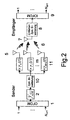
- Fig.2
- ebenfalls in Blockschaltbildform die Sender/Empfänger-Frontends eines gemäß der Erfindung arbeitenden Doppler-Diversity-OFDM-Übertragungssystems,
- Fig.3
- in zwei Diagrammen (a) und (b) spektrale Leistungsdichten,
- Fig.4
- in einem Diagramm Dopplerspreizsignale,
- Fig.5
- in einem Blockschaltbild die (De)Codierungs- und (De)Modulationsteile eines Simulationssystems,
- Fig.6 bis Fig.9
- in Diagrammen die Bitfehlerrate BER des Verfahrens nach der Erfindung im Vergleich zu einem kontinuierlichen Doppler-Diversity(DD)-Verfahren in Abhängigkeit vom Signal/Rausch-Verhältnis SNR [dB] für vier verschiedene Simulationsfälle, und
- Fig.10
- in einem Diagramm ebenfalls die Bitfehlerrate BER des Verfahrens nach der Erfindung im Vergleich zu einem kontinuierlichen Doppler-Diversity(DD)-Verfahren in Abhängigkeit vom Signal/Rausch-Verhältnis SNR [dB] für eine Simulation, bei der die Dopplerspreizung mit einem festgelegten Satz Sendeantennen variiert wird.
- Fig.1
- in block diagram form the transceiver front-ends of a known cyclic delay diversity (CDD) -OFDM transmission system,
- Fig.2
- also in block diagram form the transmitter / receiver front ends of a Doppler diversity OFDM transmission system according to the invention,
- Figure 3
- in two diagrams (a) and (b) spectral power densities,
- Figure 4
- in a diagram Doppler spread signals,
- Figure 5
- in a block diagram the (de) coding and (de) modulation parts of a simulation system,
- Fig.6 to Fig.9
- in diagrams, the bit error rate BER of the method according to the invention in comparison with a continuous Doppler-diversity (DD) method as a function of the signal-to-noise ratio SNR [dB] for four different simulation cases, and
- Figure 10
- in a diagram also the bit error rate BER of the method according to the invention in comparison with a continuous Doppler-diversity (DD) method as a function of the signal-to-noise ratio SNR [dB] for a simulation in which the Doppler spread with a fixed set transmission antennas is varied.
Delay- und Dopplerspreizung von Mehrwegeschwundkanälen sind als Diversitätsquellen in drahtlosen Kommunikationssystemen erkannt. Eine extensive Delay- und Dopplerspreizung können allerdings nichtvernachlässigbare NachbarIntersymbolinterferenzen (ISI; Inter-symbol interference) und/oder NachbarZwischenträgerinterferenzen (ICI; Intercarrier interference) in OFDM(Orthogonal Frequency Division Multiplex)-Systemen verursachen. Im nachfolgend erläuterten Ausführungsbeispiel der vorliegenden Erfindung wird ein Verfahren zur Steigerung der Dopplerspreizung des Mehrwegeschwundkanals ohne zusätzlich verursachtes ICI beschrieben. Der Grundgedanke besteht darin, das OFDM-Zeitbereichssignal vorverzerrt über mehrere Sendeantennen auszusenden. Dieses vorgeschlagene neue Verfahren kann zusätzlich bei bereits bestehenden OFDM-Systemen eingesetzt werden, ohne dass Änderungen am Empfänger erfolgen, was es standardkompatibel macht.Delay and Doppler spread of multipath fading channels are recognized as diversity sources in wireless communication systems. However, extensive delay and Doppler spread may cause non-negligible inter-symbol interference (ISI) and / or intercarrier interference (ICI) in OFDM (Orthogonal Frequency Division Multiplex) systems. In the embodiment of the present invention explained below, a method is described for increasing the Doppler spread of the multipath fading channel without additionally causing ICI. The basic idea is to transmit the OFDM time domain signal predistorted over several transmit antennas. This proposed new method can additionally be used with existing OFDM systems without making any changes to the receiver, which makes it standard compatible.
Seit einiger Zeit findet das Multiple-Input-Multiple-Output(MIMO)-Konzept bei den Entwicklungsaktivitäten für drahtlose Kommunikationssysteme infolge der höheren Kapazität im Vergleich zu Einantennensystemen reges Interesse. MIMO-Systeme verwenden im allgemeinen mehrere Antennen beim Sender und/oder beim Empfänger. 1993 wurde ein wenig komplexes Sendeantennen-Delay-Diversity-Schema für Einträger-Übertragungssysteme vorgeschlagen, das in dem Artikel von A. Wittneben: "A new bandwidth efficient transmit antenna modulation diversity scheme for linear digital modulation" in Proceedings IEEE International Conference on Communications (ICC 1993), Mai 1993, Seiten 1630-1634 beschrieben ist.For some time, the multiple-input-multiple-output (MIMO) concept has received much interest in wireless communications development activities due to the higher capacity compared to single-antenna systems. MIMO systems generally use multiple antennas at the transmitter and / or at the receiver. 1993 became one A less complex transmit antenna delay diversity scheme has been proposed for single-carrier transmission systems as described in the article by A. Wittneben: "A new bandwidth efficient transmit antenna modulation diversity scheme for linear digital modulation" in Proceedings IEEE International Conference on Communications (ICC 1993). , May 1993, pages 1630-1634.
In engem Zusammenhang mit dieser Delay-Diversity-Lösung steht das sogenannte Cyclic-Delay-Diversity(CDD)-Schema für OFDM-Systeme, das in den bereits erwähnten Artikeln von A. Dammann, S. Kaiser: "Performance of low complex antenna diversity techniques for mobile OFDM systems" in Proceedings 3rd International Workshop on Multi-Carrier Spread-Spectrum & Related Topics (MC-SS'2001), Oberpfaffenhofen, Germany, September 2001, Seiten 53-64, ISBN 0-7923-7653-6 und von A. Dammann, S. Kaiser: "Transmit/receive antenna diversity techniques for OFDM systems" in European Transactions on Telecommunications, Vol. 13, No. 5, Seiten 531-538, September-Oktober 2002 beschrieben ist.Closely related to this delay diversity solution is the so-called cyclic delay diversity (CDD) scheme for OFDM systems, which is described in the previously mentioned articles by A. Dammann, S. Kaiser: "Performance of low complex antenna diversity techniques for mobile OFDM systems "in Proceedings 3rd International Workshop on Multi-Carrier Spread-Spectrum & Related Topics (MC-SS'2001), Oberpfaffenhofen, Germany, September 2001, pages 53-64, ISBN 0-7923-7653-6 and by A. Dammann, S. Kaiser: "Transmit / receive antenna diversity techniques for OFDM systems" in European Transactions on Telecommunications, Vol. 5, pages 531-538, September-October 2002.
Das Cyclic-Delay-Diversity(CDD)-Schema steigert die Verzögerungsspreizung (delay spread) des Kanals, ruft aber keine zusätzliche Intersymbolinterferenz (ISI) hervor. In Bezug auf OFDM-Systeme steigern (zyklische) Delay-Diversity-Einrichtungen die Frequenzselektivität und vergrößern deshalb die ausnutzbare Diversität im Frequenzbereich. So wie die Frequenzselektivität ist auch der zeitvariante Schwund, d.h. die Zeitselektivität, als Diversitätsquelle erkannt worden.The Cyclic Delay Diversity (CDD) scheme increases the delay spread of the channel, but does not produce additional intersymbol interference (ISI). With respect to OFDM systems, (cyclic) delay diversity devices increase the frequency selectivity and therefore increase the exploitable diversity in the frequency domain. As well as frequency selectivity, time-variant fading, i. the time-selectivity has been recognized as a source of diversity.
In diesem Zusammenhang wird auf den Artikel von A. M. Sayeed und B. Aszhang: "Exploiting Doppler diversity in mobile wireless communications" in Proceedings 1997 Conference on Information Sciences and Systems (CISS 1997), Baltimore, MD, USA, 1997, Seiten 287-292 hingewiesen. Wie aus dem Artikel von R. Raulefs, A. Dammann, S. Kaiser und G. Auer: "The Doppler spread - gaining diversity for future mobile radio systems" in Proceedings IEEE Global Telecommunications Conference (GLOBECOM 2003), San Francisco, CA, USA, Dezember 2003, Vol. 3, Seiten 1301-1305 zu entnehmen ist, wird Zeitdiversität durch künstliche Zunahme der Dopplerspreizung mit mehreren Antennen am Sender auf Kosten zusätzlicher Zwischenträger-Interferenz (ICI) gewonnen. Durch das nachstehend erläuterte Ausführungsbeispiel des Verfahrens nach der Erfindung wird bei einem OFDM-Übertragungssystem die Zeitdiversität ohne den Nachteil zusätzlicher ICI gesteigert.In this regard, the article by AM Sayeed and B. Aszhang: "Exploiting Doppler Diversity in mobile wireless communications "in Proceedings 1997 Conference on Information Sciences and Systems (CISS 1997), Baltimore, MD, USA, 1997, pp. 287-292, as disclosed in the article by R. Raulefs, A. Dammann, S. Kaiser and G. Auer: "The Doppler spread - gaining diversity for future mobile radio systems" in Proceedings IEEE Global Telecommunications Conference (GLOBECOM 2003), San Francisco, CA, USA, December 2003, Vol. 3, pages 1301-1305 can be seen, Time diversity is obtained by artificially increasing Doppler spread with multiple antennas at the transmitter at the expense of additional intercarrier interference (ICI). <br/><br/> By the embodiment of the method according to the invention discussed below, in an OFDM transmission system, time diversity is increased without the penalty of additional ICI.
Zunächst wird das bekannte CDD-Konzept rekapituliert, da es das Gegenstück des hier vorgeschlagenen neuen Zeitdiversitätsschemas ist. Danach wird das neuartige Zeitbereich-Diversitätskonzept nach der Erfindung detailliert dargestellt und es wird mit Zeitdiversitätssystemen verglichen, die ICI hervorrufen.First, the well-known CDD concept is recapitulated since it is the counterpart of the new time diversity scheme proposed here. Thereafter, the novel time domain diversity concept of the invention is detailed and compared to time diversity systems that cause ICI.
In OFDM-Systemen verursacht die Verzögerungsspreizung von Mehrwegeschwundkanälen eine nichtflache Kanalübertragungscharakteristik im Frequenzbereich über die verfügbare Bandbreite. Tiefe Schwundeinbrüche können für manche Unterträger beobachtet werden, was bedeutet, dass Signale aus unterschiedlichen Ausbreitungswegen destruktiv überlagert sein können, wogegen andere eine konstruktive Überlagerung der verschiedenen Mehrwegeausbreitungswege zeigen können.In OFDM systems, the delay spread of multipath fading channels causes a non-flat channel transmission characteristic in the frequency domain over the available bandwidth. Deep fading can be observed for some subcarriers, which means that signals from different propagation paths can be destructively superimposed, while others can show constructive superposition of the various multipath propagation pathways.
Die grundsätzliche Idee von Delay-Diversity-Systemen besteht schlechthin darin, verzögerte Replikas des Zeitbereichssignals über mehrere Sendeantennen auszusenden und somit die beobachtbare Verzögerungsspreizung am Empfänger zu steigern. Einfache Verzögerungen können jedoch ISI verursachen, da sie die maximal beobachtbare Kanalverzögerungsspreizung am Empfänger vergrößern. Dieses Problem kann für OFDM-Übertragungssysteme durch die Zuführung zyklischer Verzögerungen (zyklische Verschiebungen) an das Zeitbereichssignal gelöst werden, bevor die zyklische Erweiterung hinzugefügt wird, wie dies in Fig.1 gezeigt ist.The basic idea of delay diversity systems is simply to send out delayed replicas of the time domain signal over several transmit antennas, thus increasing the observable delay spread at the receiver. However, simple delays can cause ISI since they increase the maximum observable channel delay spread at the receiver. This problem can be solved for OFDM transmission systems by supplying cyclic delays (cyclic shifts) to the time domain signal before adding the cyclic expansion, as shown in Fig.1.
In Fig.1 sind die Frontends des Senders und des Empfängers des bekannten CDD-OFDM-Systems dargestellt. Dieses Schema verbessert die Frequenzselektivität der Kanalübertragungsfunktion ohne eine Zunahme der beobachtbaren Zeitbereich-Kanalverzögerungsspreizung am Empfänger. Die einer Fast Fourier Transformation (FFT) unterzogenen Signal-Unterträger 1,...,N FFT werden im Sender in einem OFDM-Modulator 1 kombiniert und zusammengefasst über ein Leistungsverteilglied 2 auf M Antennenkanäle geleitet. Danach folgen für jeden Antennenkanal m, 0,...,M-1 ein Zeitverzögerungsglied 3 für die Einführung einer zyklischen Verzögerung und ein Glied 4 zur Einführung einer zyklischen Erweiterung. Danach folgt in jedem Antennenkanal m die betreffende Sendeantenne 5, von denen aus die Aussendung auf einen Funkübertragungsweg 6 erfolgt. Im Empfänger des Funkübertragungssystems werden die von einer Empfangsantenne 7 aufgenommenen Signale über eine Einrichtung 8 zum Entfernen der zyklischen Erweiterung geführt und einem OFDM-Demodulator 9 eingegeben, so dass dann nach inverser FFT die Signal-Unterträger 1,...,N FFT wieder entnehmbar sind.In Fig.1, the front ends of the transmitter and the receiver of the known CDD-OFDM system are shown. This scheme improves the frequency selectivity of the channel transfer function without an increase in the observable time domain channel delay spread at the receiver. The
Da das im vorhergehenden Teil beschriebene CDD-System die Frequenzselektivität des Mehrwegekanals steigert, besteht der der Erfindung zu Grunde liegende Gedanke nun darin, die Zeitselektivität des Schwundkanals auf ähnliche Weise zu steigern. In Fig.2 zeigen die Frontends des Senders bzw. des Empfängers das allgemeine Konzept des durch die Erfindung vorgeschlagenen Verfahrens, wobei für sich entsprechende Elemente Bezugszeichen verwendet werden, die mit denjenigen von Fig.1 übereinstimmen. 
Der durch das Leistungsverteilglied 2 eingeführte Faktor ![]()


![]()
Nachfolgend liegt die Konzentration auf dem zu multiplizierenden Signal 
Es wird ein OFDM-Übertragungssystem betrachtet, das eine Fast-Fourier-Transformationslänge (FFT-Länge) von N FFT und einen Unterträgerabstand von Δf sc verwendet. Die Spreizsignale γ m (t) werden dann zu Zeitpunkten t = k·T s abgetastet, wobei 

wobei k der diskrete Zeitindex ist.Consider an OFDM transmission system using a fast Fourier transform length (FFT length) of N FFT and a subcarrier spacing of Δf sc . The spread signals γ m ( t ) are then sampled at times t = k · T s , where
where k is the discrete time index.
Die Signale γ' m (k) steigern die Schwundschwankungen während einer OFDM-Symbolperiode und verursachen deswegen zusätzliche ICI. Da Interesse daran besteht, die Zeitselektivität des Schwundprozesses zwischen OFDM-Symbolen zu steigern, besteht die Idee schlechthin darin, γ' m (k) während eines OFDM-Symbols konstant zu halten und jenes Signal nur in OFDM-Symbolintervallen zu aktualisieren. Wenn N OFDM = N FFT + NGuard die OFDM-Symbollänge einschließlich dem Guard-Intervall bezeichnet, können die modifizierten Spreizsignale ausgedrückt werden als 
wobei "div" eine ganzzahlige Teilung bezeichnet, d.h. eine Teilung mit Rundung auf die nächste ganze Zahl nach -∞ hin. Wird γ(t) z.B. entsprechend der Gleichung (3) gewählt, so zeigt Fig.4 die Realteile der Spreizsignale γ'(k) und γ"(k) für fD = 0,2·Δf sc, N Guard = 5 und N FFT = 1024. Der Antennenindex m wurde der Einfachheit halber fortgelassen. Da die zusätzliche Dopplerspreizung 20 % des Unterträgerabstandes beträgt, wird erwartet, dass γ'(k) ernsthafte ICI verursacht. Im Gegensatz dazu ist γ"(k) während der OFDM-Symbolperioden konstant, was die beobachtbare ICI lediglich von den kanaleigenen Schwundprozessen α m, l (t) abhängig macht. Infolge der Stufenform der Dopplerspreizsignale lässt sich dieses Verfahren als diskontinuierliche Dopplerdiversität (DDD; Discontinuous Doppler Diversity) bezeichnen.The signals γ ' m ( k ) increase the fading variations during an OFDM symbol period and therefore cause additional ICI. Since there is interest in increasing the time-selectivity of the fading process between OFDM symbols, the idea consists simply in keeping γ 'm (k) during an OFDM symbol is constant and to update that signal only in OFDM symbol intervals. If N OFDM = N FFT + N Guard denotes the OFDM symbol length including the guard interval, the modified spread signals can be expressed as
where "div" denotes an integer pitch, ie a pitch with rounding to the nearest integer to -∞. If γ ( t ) is selected according to equation (3), for example, FIG. 4 shows the real parts of the spread signals γ '( k ) and γ "( k ) for f D = 0.2 · Δ f sc , N Guard = 5 and N FFT = 1024. The antenna index m has been omitted for simplicity Since the additional Doppler spread is 20% of subcarrier spacing, γ '(k) is expected to cause serious ICI In contrast, γ "( k ) is during OFDM Symbol periods constant, making the observable ICI dependent only on the channel's own fading processes α m, l ( t ). Due to the step shape of the Doppler spread signals, this method can be referred to as Discontinuous Doppler Diversity (DDD).
Es wird nun das Simulationssystem vorgestellt, das zum Nachweis der Wirksamkeit des DDD-Schemas verwendet wurde.We will now introduce the simulation system used to demonstrate the effectiveness of the DDD scheme.
Für die Simulationen wird ein codiertes OFDMA-System betrachtet. Die Auslegungen des (De)Codier- und (De)Modulationsteils im Sender und Empfänger sind in Fig.5 dargestellt. Der Sender besteht aus einer Quelle 12 der Signale, einem Kanalcodierer 13, einem Interleaver 14, einem Modulator 15 und einem Seriell-Parallel-Wandler 16. Der Empfänger enthält einen Parallel-Seriell-Wandler 17, einen Demodulator 18, einen Deinterleaver 19, einen Kanaldecodierer 20 und eine Senke 21 für die Signale. Am Sender werden im Kanalcodierer 13 die aus der Quelle 12 kommenden Informationsbits codiert, wobei ein Faltungscode mit Rate 1/3 mit Gedächtnistiefe 8 oder ein Turbocode mit Rate 1/3 verwendet wird.For the simulations, a coded OFDMA system is considered. The interpretations of the (de) coding and (de) modulation part in the transmitter and receiver are shown in FIG. The transmitter consists of a
Die Bits eines Codeworts werden dann im Interleaver 14 zufällig verwürfelt (interleaved), im Modulator 15 zu einer 4-QAM-Konstellation gemapped und im Seriell-Parallel-Wandler 16 einem OFDM-Rahmen zugeteilt, der aus 96 OFDM-Symbolen unter Verwendung von N FFT = 1024 Unterträgern besteht. Auf Seiten des Empfängers sorgt nach der Parallel-Seriell-Wandlung des OFDM-Rahmens im Parallel-Seriell-Wandler 17 der Demodulator 18 für Log-Likelihood-Werte LL unter der Voraussetzung, dass die Kanalzustandsinformation CSI vollkommen bekannt ist. Diese LL-Werte werden im Deinterleaver 19 entwürfelt und für eine Soft-Decision-Maximum-Likelihood(SDML)-Viterbi-Decodierung bzw. Turbodecodierung im Kanaldecodierer 20 benutzt.The bits of a codeword are then randomly scrambled (interleaved) in the
Das Modell für das Kanalausbreitungsszenario ist ein Rayleigh-Schwundmodell mit 2 oder 12 Abgriffen Pfaden von gleichem Abstand mit einem exponentiellen Leistungsabfall von 1 dB von Abgriff Pfad zu AbgriffPfad und einer maximalen Verzögerungsspreizung von 60 bzw. 176 Abtastproben-Abtastwerten. Für die Simulationen wird ein DDD-Sender mit Sende/Empfangs-Frontends verwendet, wie sie in Fig.2 gezeigt sind. Die antennenspezifischen DopplerSpreizsignale werden so gewählt, dass die Dopplerspektren der einen Bestandteil bildenden Schwundkanäle symmetrisch in Bezug auf die Frequenz null verschoben werden und aneinander angrenzen. Es wird 


Jakes-Spektralform
Jakes-spectral
Nachfolgend sind die Simulationsergebnisse angegeben.The simulation results are given below.
Fig.6 bis Fig.9 zeigen die Bitfehlerrate (BER) der Simulation des Verfahrens nach der Erfindung im Vergleich zu einem kontinuierlichen Doppler-Diversity(DD)-Verfahren, das Gleichung (4) benutzt. Zur Bezugnahme ist die Bitfehlerrate (BER) eines Einsendeantennensystems eingezeichnet. Für das kontinuierliche Doppler-Diversity-System mit zwei Sendeantennen ist die Bitfehler-Leistungsfähigkeit nahezu gleich derjenigen des Einsendeantennensystems, was bedeutet, dass der Diversitätsgewinn infolge der zusätzlichen Dopplerspreizung durch den zusätzlichen ICI-Verlust aufgehoben wird. Wird die Anzahl der Sendeantennen auf ein Dreisendeantennensystem gesteigert, so wächst der ICI-Verlust weiter an, um das Gleichgewicht mit dem Diversitätsgewinn zu halten, d.h. die Bitfehlerrate (BER) wird nahezu gleich im Vergleich zum Einsendeantennen-Bezugssystem.Figures 6-9 show the bit error rate (BER) of the simulation of the method of the invention as compared to a continuous Doppler diversity (DD) method using equation (4). For reference, the bit error rate (BER) of a return antenna system is shown. For the continuous Doppler diversity system with two transmit antennas, the bit error performance is nearly equal to that of the return antenna system, which means that the diversity gain due to the additional Doppler spread is canceled out by the additional ICI loss. As the number of transmit antennas on a three-terminal antenna system increases, the ICI loss continues to increase to maintain balance with the diversity gain, i. the bit error rate (BER) becomes almost equal compared to the return antenna reference system.
Für das durch die Erfindung vorgeschlagene DDD-System. verbessert sich die Bitfehlerratenleistung mit einer anwachsenden Anzahl von Sendeantennen. Die ausnutzbare Zeitdiversität nimmt zu und die ICI bleibt gleich wie beim Einsendeantennen-Bezugssystem. Die Ergebnisse in Fig.6 zeigen eine Lücke von etwa 4 dB Verlust für die faltungscodierten 2-AbgriffPfad-Kanalsimulationsergebnisse im Vergleich zu den Ergebnissen für den statistisch unabhängigen Rayleigh Kanal (IR; Independent Rayleigh)-Ergebnissen. Die IR-Leistungsergebnisse beruhen auf der Annahme eines perfekten Interleaving, so dass die Gesamt-Kanalschwundkoeffizienten unkorreliert sind.For the DDD system proposed by the invention. Bit error rate performance improves with an increasing number of transmit antennas. The exploitable time diversity increases and the ICI remains the same as the submit antenna reference system. The results in Figure 6 show a gap of about 4 dB loss for the convolutionally coded 2-tap path simulation results compared to the results for the random independent Rayleigh channel (IR) results. The IR performance results are based on the assumption of a perfect interleaving such that the overall channel fading coefficients are uncorrelated.
Bei der Simulationsausführung wird diese Annahme durch Erzeugung unabhängiger komplexwertiger, nach Gauß verteilter Freqüenzbereich-Schwundkoeffizienten mit Nullmitte Mittelwert Null und einer Varianz von 1/2 pro komplexer Dimension modelliert, d.h. die Simulationskette vom Interleaver zum Deinterleaver wird als ein Ersatz-IR-Schwundkanal betrachtet.In the simulation implementation, this assumption is modeled by generating independent complex Gaussian distributed zero-mean-space fading coefficients with zero mean zero and a variance of 1/2 per complex dimension, i. the interleaver to deinterleaver simulation chain is considered a replacement IR fading channel.
In Fig.7 wird der gleiche 2-AbgriffPfad-Rayleigh-Schwundkanal in Kombination mit einer Turbo-Kanalcodierung verwendet. Die Leistungsfähigkeit von Faltungs- und Turbocodierung ist ähnlich. Allerdings ist die Lücke für das turbocodierte 2-Abgriff-Kanalszenario zur IR-Kurve größer als 6 dB, da der Turbo-Codierer die Diversität, wenn verfügbar, noch weiter ausnutzen kann.In Fig. 7, the same 2-tap path Rayleigh fading channel is used in combination with turbo channel coding. The performance of convolution and turbo coding is similar. However, the gap for the turbocharged 2-tap IR channel channel scenario is greater than 6 dB because the turbo encoder can further exploit diversity, if available.
In Fig.8 sind die Ergebnisse für einen 12-AbgriffPfad-Rayleigh-Schwundkanal und Faltungscode dargestellt. Dieser Mehrwegekanal bietet mehr Frequenzdiversität als der 2-AbgriffPfad-Kanal. Deshalb sind die Verbesserungen lediglich etwa 2 dB für das faltungscodierte Szenario. Eine weitere Steigerung der Sendeantennenzahl verschiebt die Ergebnisse näher an die Leistungsfähigkeit der IR-Kanal-Grenze. Die Grenze liegt für drei Sendeantennen bei Verwendung des DDD-Sytems um etwa 1,5 dB weg.Figure 8 shows the results for a 12-tap Path Rayleigh fading channel and convolutional code. This multipath channel provides more frequency diversity than the 2-tap path channel. Therefore, the improvements are only about 2 dB for the convolutionally coded scenario. Further increase of the transmit antenna number shifts the results closer to the performance of the IR channel boundary. The limit is about 1.5 dB for three transmit antennas when using the DDD system.
Fig.9 zeigt den gleichen Simulationsaufbau mit Turbo-Kanalcodierung. Der Turbocodierer Turbocode kann die zusätzliche Diversität des Mehrwegs und von DDD im Vergleich zum DD-System ausnutzen, wird aber nicht - wie im DD-System - durch zusätzliche Interferenz beeinträchtigt. Es besteht jedoch noch ein Leistungsverlust von 3 dB gegenüber der IR-Kurve, welche die am besten ausnutzbare Diversität bietet. Diese Lücke von 3 dB könnte durch Zunahme der Sendeantennenzahl verkleinert werden, wobei weiterhin das DDD-System benutzt wird.FIG. 9 shows the same simulation setup with turbo channel coding. The turbo coder Turbocode can exploit the additional diversity of the multipath and DDD compared to the DD system, but is not - as in the DD system - affected by additional interference. However, there is still a 3 dB power loss over the IR curve, which offers the most exploitable diversity. This 3 dB gap could be reduced by increasing the transmit antenna number, while still using the DDD system.
Grundsätzlich übertrifft das DDD-System sein Doppler-Diversity(DD)-Gegenstück ohne Erhöhung dermit geringerer Komplexität, da zusätzliche ICI nicht auftritt und keine Kompensationsmaßnahmen notwendig sind. Je höher die anfängliche Dopplerspreizung des Kanals ist, desto größer ist deshalb der Vorteil des DDD-Systems, was ICI angeht. Das Leistungsvermögen der beiden Systeme DD und DDD bleibt jedoch fast gleich, wenn ICI auf einem solchen Niveau ist, dass sie vernachlässigbar ist, d.h. für niedrige Dopplerspreizungen im Vergleich zum Unterträgerabstand.Basically, the DDD system surpasses its Doppler diversity (DD) counterpart without increasing complexity, since additional ICI does not occur and no compensation measures are necessary. Therefore, the higher the initial Doppler spread of the channel, the greater the advantage of the DDD system in terms of ICI. However, the performance of the two systems DD and DDD remains almost the same when ICI is at such a level that it is negligible, i. for low Doppler spreads compared to subcarrier spacing.
Darüber hinaus vereinfacht das DDD-Schema den Systemaufbau, weil sich seine Bitfehlerraten(BER)-Leistungsfähigkeit mit einer zunehmenden Anzahl von Sendeantennen monoton verbessert, wogegen im Fall des kontinuierlichen Doppler-Diversity-Verfahrens ein Optimum gefunden werden musssich ab einer bestimmten Anzahl an Sendeantennen wieder eine Verschlechterung durch die überwiegende ICI einstellt. Ein Optimierungsproblem für die Fehlerrate bezüglich der Anzahl der Sendeantennen existiert deshalb nicht für DDD beim Systemdesign.In addition, the DDD scheme simplifies the system design because its bit error rate (BER) performance monotonously improves with an increasing number of transmit antennas, whereas in the case of the continuous Doppler diversity technique, an optimum must be found from a certain number of transmit antennas worsening by the vast ICI. An optimization problem for the error rate regarding the number of transmit antennas therefore does not exist for DDD in system design.
In Fig.10 wird die Dopplerspreizung mit einem festgelegten Satz Sendeantennen verändert. Die Bitfehlerraten(BER)-Leistungsfähigkeit ist für alle verschiedenen Dopplerspreizungen ganz ähnlich. Schon die Anfangsdopplerspreizung von 1% ist bereits zuverlässig, um durch das diskontinuierliche Dopplerdiversitätsschema DDD (Discontinuous Doppler Diversity) ausgenutzt zu werden. Der Kanalcode könnte die Diversität nicht erfolgreich weiter ausnutzen, da die mögliche Diversität in eine Sättigung konvergiert. Die fehlende Diversitätslücke gegenüber den IR(Independent Rayleigh)-Ergebnissen könnte durch Anwendung von Frequenzdiversitätssystemen, wie z.B. CDD, verkleinert werden.In Fig. 10, the Doppler spread is changed with a fixed set of transmit antennas. The bit error rate (BER) performance is quite similar for all different Doppler spreads. Even the initial Doppler spread of 1% is already reliable, to be exploited by the discontinuous Doppler diversity scheme DDD (Discontinuous Doppler Diversity). The channel code could not successfully exploit diversity as the potential diversity converges to saturation. The lack of diversity gap over the IR (Independent Rayleigh) results could be achieved by using frequency diversity systems, such as, e.g. CDD, be scaled down.
Durch die Erfindung wird somit ein Verfahren zur Steigerung der Dopplerspreizung von Schwundkanälen vorgeschlagen, das zusätzliche Zeitselektivität und daher Diversität im Zeitbereich vorsieht. Das neue Schema beruht auf dem Gebrauch mehrerer Sendeantennen, wobei das Sendesignal mit einem sendeantennenspezifischen Signal multipliziert wird, was bewirkt, dass die Schwundprozesse des Kanals effektiv gespreizt werden. Darüber hinaus wird ICI in OFDM-Systemen infolge dieser gesteigerten Dopplerspreizung vermieden, indem die Spreizsignale für die Dauer einer OFDM-Symbolperiode konstant gehalten werden und das Signal nur zwischen aufeinanderfolgenden OFDM-Symbolen geändert wird. Dieses Verfahren verlangt keine Veränderungen am Empfänger, was es standardkompatibel macht.The invention thus proposes a method for increasing the Doppler spread of fading channels, which provides additional time selectivity and therefore diversity in the time domain. The new scheme relies on the use of multiple transmit antennas, where the transmit signal is multiplied by a transmit antenna specific signal, causing the fading processes of the channel to be effectively spread. Moreover, ICI is avoided in OFDM systems due to this increased Doppler spread by keeping the spread signals constant for the duration of an OFDM symbol period and changing the signal only between successive OFDM symbols. This method does not require changes to the receiver, making it standard compatible.
Die vorliegende Erfindung ist von großem Interesse für die Informations- und Kommunikationsbranche und kann unter anderem die Übertragungsqualität und Kapazität bestehender Funksysteme wie auch zukünftiger Funksysteme verbessern. Von Bedeutung ist, dass das Verfahren nach der Erfindung auch so implementiert werden kann, dass es auch in Systemen nach bestehenden Standards eingesetzt werden kann, ohne dass eine Modifikation der Standards erforderlich ist.The present invention is of great interest to the information and communications industry and may, among other things, improve the transmission quality and capacity of existing radio systems as well as future radio systems. Importantly, the method of the invention may also be implemented so that it can be used in existing standards systems without requiring modification of the standards.
Des weiteren kann die Erfindung in allen Systemen vorteilhaft sein, die bislang aus einem gewissen Grad an zeitlicher Selektivität Nutzen gezogen haben, wobei dieser Nutzen aufgrund des Verlustes an Signalenergie und der Störung der Nachbarsignale bislang nur beschränkt verwertbar war. Dies könnte auch funklose Übertragungsmedien wie Glasfaser mit einschlie-βen, die anhand der zusätzlichen zeitlichen Selektivität ihre vorhandenen Dispersionseffekte gezielter nutzen können, um diese auszunutzen, beispielsweise mit einer geeigneten Kanalcodierung.Furthermore, the invention may be advantageous in all systems that have hitherto benefited from a certain degree of temporal selectivity, which benefit has hitherto been of limited use due to the loss of signal energy and the disturbance of neighboring signals. This could also include wireless transmission media such as glass fiber, which, based on the additional temporal selectivity, can better utilize their existing dispersion effects to exploit them, for example with suitable channel coding.
Des weiteren lässt sich die zeitliche Selektivität auch vorteilhaft in ein MC-CDMA System integrieren.Furthermore, the temporal selectivity can also be advantageously integrated into an MC-CDMA system.
- 11
- OFDM-ModulatorOFDM modulator
- 22
- LeistungsverteilgliedLeistungsverteilglied
- 33
- ZeitverzögerungsgliedTime delay element
- 44
- Glied zur Einführung einer zyklischen ErweiterungLink to the introduction of a cyclical extension
- 55
- Sendeantennentransmitting antennas
- 66
- Funkübertragungswegradio transmission
- 77
- Empfangsantennereceiving antenna
- 88th
- Einrichtung zum Entfernen der zyklischen ErweiterungDevice for removing the cyclic extension
- 99
- OFDM-DemodulatorOFDM demodulator
- 1010
- Erweiterungsgliedextenders
- 1111
- Multipliziergliedmultiplier
- 1212
- Quellesource
- 1313
- Kanalcodiererchannel encoder
- 1414
- Interleaverinterleaver
- 1515
- Modulatormodulator
- 1616
- Seriell-Parallel-WandlerSerial-to-parallel converter
- 1717
- Parallel-Seriell-WandlerParallel to serial converter
- 1818
- Demodulatordemodulator
- 1919
- Deinterleaverdeinterleaver
- 2020
- KanaldecodiererChannel decoder
- 2121
- Senkedepression
Claims (19)
Applications Claiming Priority (1)
| Application Number | Priority Date | Filing Date | Title |
|---|---|---|---|
| DE102004034424A DE102004034424A1 (en) | 2004-07-15 | 2004-07-15 | Method for transmitting digital message signals |
Publications (3)
| Publication Number | Publication Date |
|---|---|
| EP1617569A2 true EP1617569A2 (en) | 2006-01-18 |
| EP1617569A3 EP1617569A3 (en) | 2006-05-03 |
| EP1617569B1 EP1617569B1 (en) | 2007-09-19 |
Family
ID=35134775
Family Applications (1)
| Application Number | Title | Priority Date | Filing Date |
|---|---|---|---|
| EP05014739A Not-in-force EP1617569B1 (en) | 2004-07-15 | 2005-07-07 | Method for transmission of digital information signals with a plurality of antennas |
Country Status (3)
| Country | Link |
|---|---|
| EP (1) | EP1617569B1 (en) |
| AT (1) | ATE373902T1 (en) |
| DE (2) | DE102004034424A1 (en) |
Cited By (1)
| Publication number | Priority date | Publication date | Assignee | Title |
|---|---|---|---|---|
| EP2071758A1 (en) | 2007-12-11 | 2009-06-17 | Sony Corporation | OFDM-Transmitting apparatus and method, and OFDM-receiving apparatus and method |
Citations (1)
| Publication number | Priority date | Publication date | Assignee | Title |
|---|---|---|---|---|
| EP1289168A1 (en) * | 2001-08-31 | 2003-03-05 | Deutsches Zentrum für Luft- und Raumfahrt e.V. | Method for radio transmission of digital data systems |
-
2004
- 2004-07-15 DE DE102004034424A patent/DE102004034424A1/en not_active Withdrawn
-
2005
- 2005-07-07 EP EP05014739A patent/EP1617569B1/en not_active Not-in-force
- 2005-07-07 DE DE502005001518T patent/DE502005001518D1/en active Active
- 2005-07-07 AT AT05014739T patent/ATE373902T1/en not_active IP Right Cessation
Patent Citations (1)
| Publication number | Priority date | Publication date | Assignee | Title |
|---|---|---|---|---|
| EP1289168A1 (en) * | 2001-08-31 | 2003-03-05 | Deutsches Zentrum für Luft- und Raumfahrt e.V. | Method for radio transmission of digital data systems |
Non-Patent Citations (3)
| Title |
|---|
| DAMMANN A ET AL: "TRANSMIT/RECEIVE-ANTENNA DIVERSITY TECHNIQUES FOR OFDM SYSTEMS" EUROPEAN TRANSACTIONS ON TELECOMMUNICATIONS, WILEY & SONS, CHICHESTER, GB, Bd. 13, Nr. 5, September 2002 (2002-09), Seiten 531-538, XP001133087 ISSN: 1124-318X * |
| RAULEFS R ET AL: "The doppler spread - gaining diversity for future mobile radio systems" GLOBECOM'03. 2003 - IEEE GLOBAL TELECOMMUNICATIONS CONFERENCE. CONFERENCE PROCEEDINGS. SAN FRANCISCO, DEC. 1 - 5, 2003, IEEE GLOBAL TELECOMMUNICATIONS CONFERENCE, NEW YORK, NY : IEEE, US, Bd. VOL. 7 OF 7, 1. Dezember 2003 (2003-12-01), Seiten 1301-1305, XP010677505 ISBN: 0-7803-7974-8 * |
| XIAONNNG PENG ET AL: "Packet transmission in fourth-generation broadband multimedia wireless communication systems" INFORMATION, COMMUNICATIONS AND SIGNAL PROCESSING, 2003 AND FOURTH PACIFIC RIM CONFERENCE ON MULTIMEDIA. PROCEEDINGS OF THE 2003 JOINT CONFERENCE OF THE FOURTH INTERNATIONAL CONFERENCE ON SINGAPORE 15-18 DEC. 2003, PISCATAWAY, NJ, USA,IEEE, Bd. 2, 15. Dezember 2003 (2003-12-15), Seiten 916-920, XP010701273 ISBN: 0-7803-8185-8 * |
Cited By (5)
| Publication number | Priority date | Publication date | Assignee | Title |
|---|---|---|---|---|
| EP2071758A1 (en) | 2007-12-11 | 2009-06-17 | Sony Corporation | OFDM-Transmitting apparatus and method, and OFDM-receiving apparatus and method |
| EP2071757A1 (en) | 2007-12-11 | 2009-06-17 | Sony Corporation | OFDM-Transmitting apparatus and method, and OFDM-receiving apparatus and method |
| EP2234306A1 (en) | 2007-12-11 | 2010-09-29 | Sony Corporation | OFDM-Transmitting apparatus and method, and OFDM-receiving apparatus and method |
| EA015539B1 (en) * | 2007-12-11 | 2011-08-30 | Сони Корпорейшн | Ofdm-transmitting apparatus and method and ofdm-receiving apparatus and method |
| EP2387173A2 (en) | 2007-12-11 | 2011-11-16 | Sony Corporation | Transmitting apparatus and method, and receiving apparatus and method |
Also Published As
| Publication number | Publication date |
|---|---|
| ATE373902T1 (en) | 2007-10-15 |
| DE102004034424A1 (en) | 2006-02-16 |
| EP1617569A3 (en) | 2006-05-03 |
| EP1617569B1 (en) | 2007-09-19 |
| DE502005001518D1 (en) | 2007-10-31 |
Similar Documents
| Publication | Publication Date | Title |
|---|---|---|
| DE60303598T2 (en) | METHOD AND SYSTEM FOR MULTICANAL TRANSMITTER AND RECEIVER WITH AMPLITUDE AND PHASE CALIBRATION | |
| DE69929788T2 (en) | METHOD AND DEVICE FOR DIVERSITY TRANSMISSION | |
| DE60217706T2 (en) | STFBC CODING / DECODING DEVICE AND METHOD IN AN OFDM MOBILE COMMUNICATION SYSTEM | |
| EP2289213B1 (en) | Apparatus for assigning and assessing transmission symbols | |
| DE60211705T2 (en) | METHOD AND DEVICE FOR PROCESSING DATA FOR TRANSMISSION IN A MULTI-CHANNEL COMMUNICATION SYSTEM USING A SELECTIVE CHANNEL TRANSMISSION | |
| DE602004013462T2 (en) | BROADCAST TRANSMISSION WITH SPATIAL SPREAD IN A MULTIPLE COMMUNICATION SYSTEM | |
| DE60035439T2 (en) | DIFFERENTIAL ROOM TIME BLOCK CODING | |
| DE202008018337U1 (en) | Apparatus for enabling fast decoding of transmissions with multiple code blocks | |
| DE202008018270U1 (en) | Transmit diversity for acknowledgment and category 0 bits in a wireless communication system | |
| DE202008018251U1 (en) | Transmitter for CCFI in a wireless communication system | |
| DE602004006583T2 (en) | Apparatus and method for suppressing interference signals in a multiple antenna system | |
| DE102007051356A1 (en) | Signals transmitting method for use in orthogonal frequency division multiplexing communication system, involves selecting orthogonal frequency division multiplexing signals as signal group, and multiplying coding sample with group | |
| DE60123282T2 (en) | TRANSMITTING A DIGITAL SIGNAL | |
| DE202004021918U1 (en) | Frequency-selective transmit signal weighting for multiple antenna communication systems | |
| DE69830641T2 (en) | INTERCONNECTION SYSTEM WITH DIVERSITY IN AN ORTHOGONAL FREQUENCY MULTIPLEX ENVIRONMENT, AND OPERATING PROCESS | |
| EP1617569B1 (en) | Method for transmission of digital information signals with a plurality of antennas | |
| EP1223700A1 (en) | MC-CDMA transmission system and method with adaptive mapping | |
| DE19543622C2 (en) | Method and device for the bidirectional transmission of high-rate digital signals | |
| DE60209234T2 (en) | TRANSMISSION PROCEDURE WITH REDUCED INTERFERENCE IN A STTD SCHEME | |
| EP1605653B1 (en) | Method of wireless transmission of signals, using equalisation measures | |
| DE10142404B4 (en) | Method for the radio transmission of digital message signals | |
| DE102005044963B4 (en) | Method for transmitting digital message signals | |
| EP2026519A1 (en) | Predistortion for a space-time block coding | |
| DE10162545C1 (en) | Multi-carrier data transmission method with adaptive modulation of data dependent on actual channel status information | |
| DE102005053714B4 (en) | Interleaver and deinterleaver for MIMO multiple antenna systems |
Legal Events
| Date | Code | Title | Description |
|---|---|---|---|
| PUAI | Public reference made under article 153(3) epc to a published international application that has entered the european phase |
Free format text: ORIGINAL CODE: 0009012 |
|
| AK | Designated contracting states |
Kind code of ref document: A2 Designated state(s): AT BE BG CH CY CZ DE DK EE ES FI FR GB GR HU IE IS IT LI LT LU LV MC NL PL PT RO SE SI SK TR |
|
| AX | Request for extension of the european patent |
Extension state: AL BA HR MK YU |
|
| PUAL | Search report despatched |
Free format text: ORIGINAL CODE: 0009013 |
|
| AK | Designated contracting states |
Kind code of ref document: A3 Designated state(s): AT BE BG CH CY CZ DE DK EE ES FI FR GB GR HU IE IS IT LI LT LU LV MC NL PL PT RO SE SI SK TR |
|
| AX | Request for extension of the european patent |
Extension state: AL BA HR MK YU |
|
| RIC1 | Information provided on ipc code assigned before grant |
Ipc: H04B 7/06 20060101AFI20051101BHEP Ipc: H04L 27/26 20060101ALI20060315BHEP |
|
| RAP1 | Party data changed (applicant data changed or rights of an application transferred) |
Owner name: DEUTSCHES ZENTRUM FUER LUFT- UND RAUMFAHRT E.V. |
|
| 17P | Request for examination filed |
Effective date: 20060811 |
|
| 17Q | First examination report despatched |
Effective date: 20060929 |
|
| AKX | Designation fees paid |
Designated state(s): AT BE BG CH CY CZ DE DK EE ES FI FR GB GR HU IE IS IT LI LT LU LV MC NL PL PT RO SE SI SK TR |
|
| GRAP | Despatch of communication of intention to grant a patent |
Free format text: ORIGINAL CODE: EPIDOSNIGR1 |
|
| GRAS | Grant fee paid |
Free format text: ORIGINAL CODE: EPIDOSNIGR3 |
|
| GRAA | (expected) grant |
Free format text: ORIGINAL CODE: 0009210 |
|
| AK | Designated contracting states |
Kind code of ref document: B1 Designated state(s): AT BE BG CH CY CZ DE DK EE ES FI FR GB GR HU IE IS IT LI LT LU LV MC NL PL PT RO SE SI SK TR |
|
| REG | Reference to a national code |
Ref country code: GB Ref legal event code: FG4D Free format text: NOT ENGLISH |
|
| REG | Reference to a national code |
Ref country code: CH Ref legal event code: EP |
|
| REF | Corresponds to: |
Ref document number: 502005001518 Country of ref document: DE Date of ref document: 20071031 Kind code of ref document: P |
|
| REG | Reference to a national code |
Ref country code: IE Ref legal event code: FG4D Free format text: LANGUAGE OF EP DOCUMENT: GERMAN |
|
| GBT | Gb: translation of ep patent filed (gb section 77(6)(a)/1977) |
Effective date: 20071122 |
|
| PG25 | Lapsed in a contracting state [announced via postgrant information from national office to epo] |
Ref country code: LT Free format text: LAPSE BECAUSE OF FAILURE TO SUBMIT A TRANSLATION OF THE DESCRIPTION OR TO PAY THE FEE WITHIN THE PRESCRIBED TIME-LIMIT Effective date: 20070919 Ref country code: FI Free format text: LAPSE BECAUSE OF FAILURE TO SUBMIT A TRANSLATION OF THE DESCRIPTION OR TO PAY THE FEE WITHIN THE PRESCRIBED TIME-LIMIT Effective date: 20070919 |
|
| PG25 | Lapsed in a contracting state [announced via postgrant information from national office to epo] |
Ref country code: PL Free format text: LAPSE BECAUSE OF FAILURE TO SUBMIT A TRANSLATION OF THE DESCRIPTION OR TO PAY THE FEE WITHIN THE PRESCRIBED TIME-LIMIT Effective date: 20070919 |
|
| NLV1 | Nl: lapsed or annulled due to failure to fulfill the requirements of art. 29p and 29m of the patents act | ||
| PG25 | Lapsed in a contracting state [announced via postgrant information from national office to epo] |
Ref country code: LV Free format text: LAPSE BECAUSE OF FAILURE TO SUBMIT A TRANSLATION OF THE DESCRIPTION OR TO PAY THE FEE WITHIN THE PRESCRIBED TIME-LIMIT Effective date: 20070919 |
|
| PG25 | Lapsed in a contracting state [announced via postgrant information from national office to epo] |
Ref country code: ES Free format text: LAPSE BECAUSE OF FAILURE TO SUBMIT A TRANSLATION OF THE DESCRIPTION OR TO PAY THE FEE WITHIN THE PRESCRIBED TIME-LIMIT Effective date: 20071230 Ref country code: GR Free format text: LAPSE BECAUSE OF FAILURE TO SUBMIT A TRANSLATION OF THE DESCRIPTION OR TO PAY THE FEE WITHIN THE PRESCRIBED TIME-LIMIT Effective date: 20071220 Ref country code: NL Free format text: LAPSE BECAUSE OF FAILURE TO SUBMIT A TRANSLATION OF THE DESCRIPTION OR TO PAY THE FEE WITHIN THE PRESCRIBED TIME-LIMIT Effective date: 20070919 |
|
| REG | Reference to a national code |
Ref country code: IE Ref legal event code: FD4D |
|
| ET | Fr: translation filed | ||
| PG25 | Lapsed in a contracting state [announced via postgrant information from national office to epo] |
Ref country code: PT Free format text: LAPSE BECAUSE OF FAILURE TO SUBMIT A TRANSLATION OF THE DESCRIPTION OR TO PAY THE FEE WITHIN THE PRESCRIBED TIME-LIMIT Effective date: 20080219 Ref country code: SK Free format text: LAPSE BECAUSE OF FAILURE TO SUBMIT A TRANSLATION OF THE DESCRIPTION OR TO PAY THE FEE WITHIN THE PRESCRIBED TIME-LIMIT Effective date: 20070919 Ref country code: IS Free format text: LAPSE BECAUSE OF FAILURE TO SUBMIT A TRANSLATION OF THE DESCRIPTION OR TO PAY THE FEE WITHIN THE PRESCRIBED TIME-LIMIT Effective date: 20080119 Ref country code: CZ Free format text: LAPSE BECAUSE OF FAILURE TO SUBMIT A TRANSLATION OF THE DESCRIPTION OR TO PAY THE FEE WITHIN THE PRESCRIBED TIME-LIMIT Effective date: 20070919 |
|
| PG25 | Lapsed in a contracting state [announced via postgrant information from national office to epo] |
Ref country code: RO Free format text: LAPSE BECAUSE OF FAILURE TO SUBMIT A TRANSLATION OF THE DESCRIPTION OR TO PAY THE FEE WITHIN THE PRESCRIBED TIME-LIMIT Effective date: 20070919 Ref country code: SE Free format text: LAPSE BECAUSE OF FAILURE TO SUBMIT A TRANSLATION OF THE DESCRIPTION OR TO PAY THE FEE WITHIN THE PRESCRIBED TIME-LIMIT Effective date: 20071219 |
|
| PLBE | No opposition filed within time limit |
Free format text: ORIGINAL CODE: 0009261 |
|
| STAA | Information on the status of an ep patent application or granted ep patent |
Free format text: STATUS: NO OPPOSITION FILED WITHIN TIME LIMIT |
|
| PG25 | Lapsed in a contracting state [announced via postgrant information from national office to epo] |
Ref country code: DK Free format text: LAPSE BECAUSE OF FAILURE TO SUBMIT A TRANSLATION OF THE DESCRIPTION OR TO PAY THE FEE WITHIN THE PRESCRIBED TIME-LIMIT Effective date: 20070919 |
|
| 26N | No opposition filed |
Effective date: 20080620 |
|
| PG25 | Lapsed in a contracting state [announced via postgrant information from national office to epo] |
Ref country code: IE Free format text: LAPSE BECAUSE OF FAILURE TO SUBMIT A TRANSLATION OF THE DESCRIPTION OR TO PAY THE FEE WITHIN THE PRESCRIBED TIME-LIMIT Effective date: 20070919 |
|
| PG25 | Lapsed in a contracting state [announced via postgrant information from national office to epo] |
Ref country code: MC Free format text: LAPSE BECAUSE OF NON-PAYMENT OF DUE FEES Effective date: 20080731 |
|
| PG25 | Lapsed in a contracting state [announced via postgrant information from national office to epo] |
Ref country code: EE Free format text: LAPSE BECAUSE OF FAILURE TO SUBMIT A TRANSLATION OF THE DESCRIPTION OR TO PAY THE FEE WITHIN THE PRESCRIBED TIME-LIMIT Effective date: 20070919 |
|
| PG25 | Lapsed in a contracting state [announced via postgrant information from national office to epo] |
Ref country code: SI Free format text: LAPSE BECAUSE OF FAILURE TO SUBMIT A TRANSLATION OF THE DESCRIPTION OR TO PAY THE FEE WITHIN THE PRESCRIBED TIME-LIMIT Effective date: 20070919 |
|
| PG25 | Lapsed in a contracting state [announced via postgrant information from national office to epo] |
Ref country code: CY Free format text: LAPSE BECAUSE OF FAILURE TO SUBMIT A TRANSLATION OF THE DESCRIPTION OR TO PAY THE FEE WITHIN THE PRESCRIBED TIME-LIMIT Effective date: 20070919 |
|
| PG25 | Lapsed in a contracting state [announced via postgrant information from national office to epo] |
Ref country code: BG Free format text: LAPSE BECAUSE OF FAILURE TO SUBMIT A TRANSLATION OF THE DESCRIPTION OR TO PAY THE FEE WITHIN THE PRESCRIBED TIME-LIMIT Effective date: 20071219 |
|
| PG25 | Lapsed in a contracting state [announced via postgrant information from national office to epo] |
Ref country code: AT Free format text: LAPSE BECAUSE OF NON-PAYMENT OF DUE FEES Effective date: 20080707 |
|
| REG | Reference to a national code |
Ref country code: CH Ref legal event code: PL |
|
| PG25 | Lapsed in a contracting state [announced via postgrant information from national office to epo] |
Ref country code: CH Free format text: LAPSE BECAUSE OF NON-PAYMENT OF DUE FEES Effective date: 20090731 Ref country code: LI Free format text: LAPSE BECAUSE OF NON-PAYMENT OF DUE FEES Effective date: 20090731 |
|
| PG25 | Lapsed in a contracting state [announced via postgrant information from national office to epo] |
Ref country code: BE Free format text: LAPSE BECAUSE OF NON-PAYMENT OF DUE FEES Effective date: 20080731 Ref country code: HU Free format text: LAPSE BECAUSE OF FAILURE TO SUBMIT A TRANSLATION OF THE DESCRIPTION OR TO PAY THE FEE WITHIN THE PRESCRIBED TIME-LIMIT Effective date: 20080320 Ref country code: LU Free format text: LAPSE BECAUSE OF NON-PAYMENT OF DUE FEES Effective date: 20080707 |
|
| PG25 | Lapsed in a contracting state [announced via postgrant information from national office to epo] |
Ref country code: TR Free format text: LAPSE BECAUSE OF FAILURE TO SUBMIT A TRANSLATION OF THE DESCRIPTION OR TO PAY THE FEE WITHIN THE PRESCRIBED TIME-LIMIT Effective date: 20070919 |
|
| PG25 | Lapsed in a contracting state [announced via postgrant information from national office to epo] |
Ref country code: IT Free format text: LAPSE BECAUSE OF NON-PAYMENT OF DUE FEES Effective date: 20080731 |
|
| REG | Reference to a national code |
Ref country code: DE Ref legal event code: R084 Ref document number: 502005001518 Country of ref document: DE |
|
| REG | Reference to a national code |
Ref country code: DE Ref legal event code: R084 Ref document number: 502005001518 Country of ref document: DE Effective date: 20140404 |
|
| REG | Reference to a national code |
Ref country code: FR Ref legal event code: PLFP Year of fee payment: 11 |
|
| REG | Reference to a national code |
Ref country code: FR Ref legal event code: PLFP Year of fee payment: 12 |
|
| REG | Reference to a national code |
Ref country code: FR Ref legal event code: PLFP Year of fee payment: 13 |
|
| REG | Reference to a national code |
Ref country code: FR Ref legal event code: PLFP Year of fee payment: 14 |
|
| PGFP | Annual fee paid to national office [announced via postgrant information from national office to epo] |
Ref country code: FR Payment date: 20190621 Year of fee payment: 15 |
|
| PGFP | Annual fee paid to national office [announced via postgrant information from national office to epo] |
Ref country code: GB Payment date: 20190626 Year of fee payment: 15 Ref country code: DE Payment date: 20190617 Year of fee payment: 15 |
|
| REG | Reference to a national code |
Ref country code: DE Ref legal event code: R119 Ref document number: 502005001518 Country of ref document: DE |
|
| GBPC | Gb: european patent ceased through non-payment of renewal fee |
Effective date: 20200707 |
|
| PG25 | Lapsed in a contracting state [announced via postgrant information from national office to epo] |
Ref country code: FR Free format text: LAPSE BECAUSE OF NON-PAYMENT OF DUE FEES Effective date: 20200731 Ref country code: GB Free format text: LAPSE BECAUSE OF NON-PAYMENT OF DUE FEES Effective date: 20200707 |
|
| PG25 | Lapsed in a contracting state [announced via postgrant information from national office to epo] |
Ref country code: DE Free format text: LAPSE BECAUSE OF NON-PAYMENT OF DUE FEES Effective date: 20210202 |