EP1617023A2 - Dispositif d'actionnement des serrures pour portes ou ouvrants d'un véhicule - Google Patents
Dispositif d'actionnement des serrures pour portes ou ouvrants d'un véhicule Download PDFInfo
- Publication number
- EP1617023A2 EP1617023A2 EP20050009428 EP05009428A EP1617023A2 EP 1617023 A2 EP1617023 A2 EP 1617023A2 EP 20050009428 EP20050009428 EP 20050009428 EP 05009428 A EP05009428 A EP 05009428A EP 1617023 A2 EP1617023 A2 EP 1617023A2
- Authority
- EP
- European Patent Office
- Prior art keywords
- pawl
- spring
- over
- counter
- catch
- Prior art date
- Legal status (The legal status is an assumption and is not a legal conclusion. Google has not performed a legal analysis and makes no representation as to the accuracy of the status listed.)
- Granted
Links
Images


Classifications
-
- E—FIXED CONSTRUCTIONS
- E05—LOCKS; KEYS; WINDOW OR DOOR FITTINGS; SAFES
- E05B—LOCKS; ACCESSORIES THEREFOR; HANDCUFFS
- E05B85/00—Details of vehicle locks not provided for in groups E05B77/00 - E05B83/00
- E05B85/20—Bolts or detents
- E05B85/24—Bolts rotating about an axis
- E05B85/26—Cooperation between bolts and detents
-
- E—FIXED CONSTRUCTIONS
- E05—LOCKS; KEYS; WINDOW OR DOOR FITTINGS; SAFES
- E05B—LOCKS; ACCESSORIES THEREFOR; HANDCUFFS
- E05B15/00—Other details of locks; Parts for engagement by bolts of fastening devices
- E05B15/04—Spring arrangements in locks
- E05B2015/0493—Overcenter springs
-
- E—FIXED CONSTRUCTIONS
- E05—LOCKS; KEYS; WINDOW OR DOOR FITTINGS; SAFES
- E05B—LOCKS; ACCESSORIES THEREFOR; HANDCUFFS
- E05B81/00—Power-actuated vehicle locks
- E05B81/12—Power-actuated vehicle locks characterised by the function or purpose of the powered actuators
- E05B81/14—Power-actuated vehicle locks characterised by the function or purpose of the powered actuators operating on bolt detents, e.g. for unlatching the bolt
- E05B81/15—Power-actuated vehicle locks characterised by the function or purpose of the powered actuators operating on bolt detents, e.g. for unlatching the bolt with means preventing the detent to return to its latching position before the bolt has moved to the unlatched position
-
- Y—GENERAL TAGGING OF NEW TECHNOLOGICAL DEVELOPMENTS; GENERAL TAGGING OF CROSS-SECTIONAL TECHNOLOGIES SPANNING OVER SEVERAL SECTIONS OF THE IPC; TECHNICAL SUBJECTS COVERED BY FORMER USPC CROSS-REFERENCE ART COLLECTIONS [XRACs] AND DIGESTS
- Y10—TECHNICAL SUBJECTS COVERED BY FORMER USPC
- Y10T—TECHNICAL SUBJECTS COVERED BY FORMER US CLASSIFICATION
- Y10T292/00—Closure fasteners
- Y10T292/08—Bolts
- Y10T292/1043—Swinging
- Y10T292/1044—Multiple head
- Y10T292/1045—Operating means
- Y10T292/1047—Closure
-
- Y—GENERAL TAGGING OF NEW TECHNOLOGICAL DEVELOPMENTS; GENERAL TAGGING OF CROSS-SECTIONAL TECHNOLOGIES SPANNING OVER SEVERAL SECTIONS OF THE IPC; TECHNICAL SUBJECTS COVERED BY FORMER USPC CROSS-REFERENCE ART COLLECTIONS [XRACs] AND DIGESTS
- Y10—TECHNICAL SUBJECTS COVERED BY FORMER USPC
- Y10T—TECHNICAL SUBJECTS COVERED BY FORMER US CLASSIFICATION
- Y10T292/00—Closure fasteners
- Y10T292/08—Bolts
- Y10T292/1043—Swinging
- Y10T292/1075—Operating means
- Y10T292/1082—Motor
Definitions
- the invention is directed to a device referred to in the preamble of claim 1.
- the classic components of a castle include a spring-loaded rotary latch, which cooperates when closing the door with a stationary closing part and a spring-loaded, pivot-mounted pawl, which when closing the door in at least one catch of the catch occurs.
- a so-called "snow load device” To the present device is added a so-called "snow load device". The snow load protection comes into play when the catch in electrical and / or manual operation of the pawl remains in its blocking effective closed position and does not release the closing part. Then, despite being pressed, the door can not be opened.
- This "snow load case” occurs in the case of a lock arranged in a tailgate of a vehicle when a snow load is lying on the closed tailgate. Namely, this snow load presses the tailgate so tightly into the closing part, that the restoring force of the seal and / or the spring load is not sufficient to convert the catch again into its open position. From this fact the term “snow load case” is derived. Without a “snow load device” the pawl would be moved back from its pawl spring into its locked position, where it falls into a catch of the catch and therefore holds the catch again in its closed position. The task of the snow load device is to hold the pawl in its release end position obtained by actuation until the catch has actually reached its open position. The result is that after removing the snow load from the tailgate, the already released catch is moved back from its spring load in its open position, without again an actuation would have to be done.
- a lock is known in which the force of the pawl spring always acts in the same direction on the pawl, this force is made ineffective by additional securing means.
- These securing means consist of a U-shaped Verhakungslasche on a driver, which is rotatably connected to the pawl, and control surfaces and a projection on the catch. In the case of snow fall the hooking tab engages behind the projection, whereby the driver is supported on the rotary latch and creates a gap between the rotary latch and the pawl. The effective in the snow load case latch spring force is transmitted to the catch on the catch.
- These securing means take up a relatively large amount of space in the lock.
- the invention has for its object to develop a reliable device referred to in the preamble of claim 1 species, which is inexpensive and space-saving. This is inventively achieved by the measures mentioned in claim 1, which has the following special significance.
- the invention proposes to use a so-called "Übertot Vietnamesefeder" as a pawl spring.
- This Automattot Vietnamesefeder changes at the transition of the pawl between the locked position and a release end position the sense of direction of their spring force. While the pawl is loaded in the locked position of the Mattertot Vietnamesefeder towards the rotary latch, it is directed away in the release end position of the rotary latch.
- the snow load device practically consists only of the Mattertot Vietnamesefeder, which cooperates with the pawl and with the catch. This is sufficient for the training of a snow load device.
- So no additional components required for the snow load device You can deal with the elements that are already available in a lock, namely handle, pawl spring and rotary latch.
- the previously required special components of the known snow load device are superfluous. It saves not only the manufacture and assembly of these special components, but above all valuable space in the castle.
- the invention is very simple, which is why it does not come to interference.
- the device according to the invention works very reliably.
- the snow load device 10 according to the invention consists only in the design of the pawl spring 40 in a special way, namely as a so-called "over-center spring".
- this vontot Vietnamesefeder formed as a leg spring.
- the snow load device according to the invention is characterized by the peculiarity to get along without additional lock parts.
- the rotary latch 20 is rotatably mounted on a stationary pivot 21 in the lock housing not shown in detail and is under the action of a spring load illustrated by the force arrow 22.
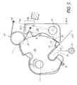
- This spring load 22 endeavors to transfer the rotary latch 20 into its open position shown in FIG. 5, which is marked there with the auxiliary line 20. 1.
- This open position 20.1 is determined by the fact that the rotary latch 20 is supported on a stationary stop 12 in the housing.
- the open position 20.1 of the rotary latch 20 of Fig. 5 indicates the position of the open tailgate.
- a fixedly seated on the vehicle closing part 11 is aligned with the opening of a provided in the rotary latch 20 section 24. If the tailgate is closed in the sense of the movement arrow 13 of FIG. 5, then the closing part 11 enters the rotary latch cutout 24 and moves the rotary latch 20 against its spring load 22 in various locking positions. There are so-called “pre-rest periods” and “main detents” on rotary traps. In the present, simplified embodiment, only a single catch 23 is shown on the rotary latch 20.
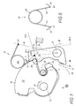
- the rotary latch 20 reaches its apparent from Fig. 1 closed position, where the detected closing part 11 has been taken deep into the interior of the castle.
- This closed position of the rotary latch 20 is marked in FIG. 1 by the auxiliary line marked 20.2.
- This closed position 20.2 is secured by an already mentioned pawl 30.
- the pawl 30 is pivotally mounted on a pin 31, which also sits fixed in the lock housing.
- the pawl 30 is spring-loaded in the first embodiment by a leg spring 40, which according to the invention as "Over-center spring" works. The particular mode of action of such a Kochtotddlingfeder 40 is explained in Fig. 6.
- the Kochtot Vietnamese Federation 40 formed as a leg spring in the first embodiment consists of a helix 43, protrude from the two legs 44, 45.
- the free ends of these legs 44, 45 form two spring ends 41, 42, of which the one spring end 41 acts on the pawl 30 and is therefore moved during pivoting of the pawl 30 and consequently "movement end” should be referred to.
- the other spring end 42 is fixed in the lock housing and rests. That is why it should be called the "Festende" of the Mattertot Vietnamesefeder40.
- Theniktotddlingfeder 40 always exerts a spring force, which seeks to divide its two legs 44, 45 apart. This is illustrated by force arrows 47 in FIG. 6.
- the Mattertot Vietnamesefeder 40 has a so-called "dead center line 46" with respect to the movement end 41 can get into two opposing layers.
- This dead center line 46 is determined by an imaginary rectilinear connection between the pivot bearing 31 of the pawl 30 and the stationary fixed end 42 of the over-center spring 40. Depending on the different pivoting positions, different effects are produced on the latch 30.
- Fig. 1 position is thus the "locked position” of the pawl 30 and illustrated there by the auxiliary line 30.2.
- the end of movement 41 of the over-center spring 40 occupies the first stable end position marked by the auxiliary line 48.1.
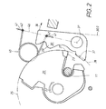
- the end of movement 41 of the Mattertot Vietnamesefeder40 is located on the dead center line 46. Then the two lying on the dead center line 46 spring forces 47 cancel each other.
- the pawl 30 is free of forces in the dead center 30.0.
- the pawl 30 is manually or motorally moved beyond the dead center 30.0 and protrudes already in the dead center with a control surface 37 in the dot-dashed Fig. 2 clarified rotary travel of the peripheral contour 25 of the rotary latch 20 into it.
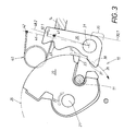
- the pawl 30 finally arrives in its release end position 30.1 shown in FIG. 3, which is delimited by an end stop 14 of the pawl.
- the pawl 30, the catch 23 of the catch 20 has been released because their counter-detent 33 is at a distance from the peripheral contour 25 of the catch 20. The resulting consequences will be discussed in more detail later.
- the movement end 41 of the over-center spring 40 is located on the opposite side of the dead center line 46 with respect to the rotary latch 20. Because of the latch stop 14, a second end position marked by the auxiliary line 28.2 is present from the end of movement 41.
- the force relationships explained in more detail in connection with FIG. 6 allow a counter torque illustrated in the direction of the arrow 32.1 in FIG. 3 to be produced which acts in a clockwise direction. This counter-torque 32.1 is opposite to the torque 32.2 described in connection with FIG. 1.
- the pawl 30 has released the rotary catch 20 both in its dead center position 30.0 of FIG. 2 and in its release end position 30.1 of FIG.
- the resilience of the elastic door seal pushes the closing part away, whereby the catch 20 is rotated by taking advantage of the spring load acting on them 22nd
- the special "snow load case” can occur, where the rotary latch 20 is still in its closed position 20.2 of FIG. 1 even after release of the pawl 30, according to FIG.
- the rotary latch 20 can not turn fast enough to move, e.g. Fig. 2 shows, with its catch 23 on the counter-latch 33 of the pawl 30 move past.
- counter torque 32.1 would be generated, the pawl back into the detent 23 or another rest, e.g. a Vorrast the catch 20 to come. This would correspond to the prior art without "snow load device”.
- the tailgate would not be open.
- the pawl 30 has, in addition to its blocking-effective arm 34, a counter-arm 35 on the opposite side with respect to its pivot bearing 31.
- On the counter-arm 35 is a control surface 37 which is generated by an angled projection 38.
- the already mentioned circumferential contour 25 of the rotary latch 20 is a circle with respect to the pivot 21. Dash-dotted in Fig. 2 and 3, the resulting rotary path is indicated, which results when the rotary latch 20 but finally in the sense of the movement arrow Turned back 26 of FIG.
- the circumferential contour 25 of the rotary latch 20 moves with its acting as counter-control surface 27 starting piece against the pawl control surface 37.
- the counter-control surface 27 abuts the pawl-side control surface 37 at. Thereby, the pawl 30 is forcibly moved in the counterclockwise direction against the torque 32.1 exerted on it in the sense of the movement arrow 39 shown in FIG.
- FIG. 4 again shows the unstable limiting case where the pawl 30 is already in the dead center position 30.0 described several times. Also in this case, an interaction of the control surface 37 and the counter-control surface 27 is ensured until the rotary latch 20 has actually reached its stop 12 and is in its apparent from Fig. 5 open position 20.1. The closing part 11 is free, as can be seen from FIG. 5.
- the depth of engagement of the pawl counter-latching 33 may be limited in the latch latch 23 by a shoulder 16 which is resiliently supported on a corresponding mating shoulder of the rotary latch 20 due to the described latch torque 32.2.
- this counter-shoulder is formed by the outline contour 25 of the rotary latch 20.
- the invention is of interest not only for the snow load case.
- the rotary latch 20 With the device according to the invention, the rotary latch 20 always has sufficient time to move from its closed position 20.2 of FIG. 1 into its open position 20.1 in FIG. 5 due to its spring load 22. The pawl "waits" until the rotation of the Rotary latch 20 is completed. Only then does she go to her from Fig. 5 apparent standby position 30.3.
- FIGS. 7 and 8 show two alternatives of an over-center spring.
- a compression spring 50 is used as Studentstot Vietnamesefeder, which is supported at one end to a stationary end 52, which is located on the already described in the first embodiment dead center 46.
- the other spring end 51 acts on the pawl 30 and therefore functions as a "movement end".
- the analogous effects act as described in connection with the first embodiment.
- the Mattertot Vietnamesefeder is designed as a tension spring 60, the ends of which act at 61, 62 in Fig. 8.
- the one end 61 is arranged movably on the pawl 30 and thus to be referred to as the "end of movement”.
- the other end of the spring 62 is fixed in position and lies on the already repeatedly mentioned dead center line 46. This end 62 is therefore the "fixed end" of the tension spring 60th
Landscapes
- Lock And Its Accessories (AREA)
Applications Claiming Priority (1)
| Application Number | Priority Date | Filing Date | Title |
|---|---|---|---|
| DE200410033735 DE102004033735B4 (de) | 2004-07-13 | 2004-07-13 | Vorrichtung zur Betätigung von Schlössern an Türen oder Klappen von Fahrzeugen |
Publications (3)
| Publication Number | Publication Date |
|---|---|
| EP1617023A2 true EP1617023A2 (fr) | 2006-01-18 |
| EP1617023A3 EP1617023A3 (fr) | 2008-05-21 |
| EP1617023B1 EP1617023B1 (fr) | 2010-06-30 |
Family
ID=35207580
Family Applications (1)
| Application Number | Title | Priority Date | Filing Date |
|---|---|---|---|
| EP20050009428 Expired - Fee Related EP1617023B1 (fr) | 2004-07-13 | 2005-04-29 | Serrure pour ouvrants ou portes d'un véhicule |
Country Status (3)
| Country | Link |
|---|---|
| US (1) | US7261339B2 (fr) |
| EP (1) | EP1617023B1 (fr) |
| DE (2) | DE102004033735B4 (fr) |
Cited By (5)
| Publication number | Priority date | Publication date | Assignee | Title |
|---|---|---|---|---|
| FR2911897A1 (fr) * | 2007-01-30 | 2008-08-01 | Valeo Securite Habitacle Sas | Serrure electrique perfectionnee pour ouvrant de vehicule automobile |
| CN101983273B (zh) * | 2008-02-28 | 2013-07-10 | 开开特股份公司 | 机动车门锁 |
| CN105569449A (zh) * | 2008-03-10 | 2016-05-11 | 索斯科公司 | 旋转式棘爪闩锁 |
| WO2018142210A1 (fr) * | 2017-02-02 | 2018-08-09 | Kiekert Ag | Verrou de portière de véhicule automobile |
| EP3604722A1 (fr) * | 2018-08-01 | 2020-02-05 | Witte Automotive GmbH | Serrure |
Families Citing this family (17)
| Publication number | Priority date | Publication date | Assignee | Title |
|---|---|---|---|---|
| EP1734209B1 (fr) | 2005-06-15 | 2013-08-14 | Intier Automotive Closures S.p.A. | Serrure pour porte de véhicule automobile |
| DE102006022436B4 (de) | 2006-05-13 | 2018-07-12 | Huf Hülsbeck & Fürst Gmbh & Co. Kg | Schloss für eine Klappe oder eine Tür an einem Fahrzeug und Verfahren zu seiner Herstellung |
| CN100545407C (zh) * | 2006-06-17 | 2009-09-30 | 重庆长安汽车股份有限公司 | 汽车中门门锁主体 |
| DE202006015093U1 (de) * | 2006-09-30 | 2006-11-30 | Emka Beschlagteile Gmbh & Co. Kg | Einpunkt-Verriegelungseinrichtung für insbesondere Schaltschränke |
| DE102007003293B4 (de) * | 2007-01-23 | 2023-11-16 | Bayerische Motoren Werke Aktiengesellschaft | Schloss mit einem verstellbaren Fangelement für eine Frontklappe eines Kraftfahrzeugs |
| WO2008144904A1 (fr) * | 2007-05-25 | 2008-12-04 | Magna Closures Inc. | Verrou de couvercle de coffre avec levier de charge électromécaniquement actionné |
| EP2071106B1 (fr) * | 2007-12-14 | 2015-10-28 | Volvo Car Corporation | Dispositif de fixation à fermeture motorisée |
| JP5177536B2 (ja) * | 2008-09-25 | 2013-04-03 | アイシン精機株式会社 | オープンルーフ開閉装置 |
| US8123260B2 (en) * | 2009-03-13 | 2012-02-28 | Sukup Manufacturing Co. | Latching device for a grain bin door |
| US8528950B2 (en) | 2010-02-01 | 2013-09-10 | Strattec Security Corporation | Latch mechanism and latching method |
| US9187935B2 (en) | 2011-10-19 | 2015-11-17 | Inteva Products, Llc | Latch assembly |
| DE102012024302A1 (de) * | 2012-12-12 | 2014-06-12 | Kiekert Aktiengesellschaft | Kraftfahrzeugtürschloss |
| DE102013217265A1 (de) * | 2013-08-29 | 2015-03-19 | Kiekert Ag | Elektrisches Kraftfahrzeugschloss mit Federspeicher |
| JP6453356B2 (ja) * | 2013-11-22 | 2019-01-16 | ゲコム コーポレーション | 車両のボンネットラッチ |
| US10641018B2 (en) * | 2014-05-30 | 2020-05-05 | Inteva Products, Llc | Latch with spring for bell crank lever |
| JP6482905B2 (ja) * | 2015-03-05 | 2019-03-13 | テイ・エス テック株式会社 | 乗物用ラッチ装置 |
| CN206581743U (zh) * | 2017-03-03 | 2017-10-24 | 恩坦华产品有限责任公司 | 用于车辆锁闩致动器机构的弹簧保持组件 |
Citations (4)
| Publication number | Priority date | Publication date | Assignee | Title |
|---|---|---|---|---|
| EP0285006A2 (fr) * | 1987-03-31 | 1988-10-05 | FIAT AUTO S.p.A. | Verrou à rattrapage automatique du jeu, notamment pour véhicule automobile |
| DE3801581C1 (fr) * | 1988-01-21 | 1988-10-13 | Bomoro Bocklenberg & Motte Gmbh & Co Kg, 5600 Wuppertal, De | |
| US4971373A (en) * | 1988-09-26 | 1990-11-20 | Mitsui Kinzoku Kogyo Kabushiki Kaisha | Noise suppressing device in lock device for vehicle |
| EP1081321A2 (fr) * | 1999-09-04 | 2001-03-07 | Kiekert Aktiengesellschaft | Serrure de porte pour véhicule automobile |
Family Cites Families (8)
| Publication number | Priority date | Publication date | Assignee | Title |
|---|---|---|---|---|
| US3666305A (en) * | 1970-12-04 | 1972-05-30 | Ford Motor Co | Door latch assembly |
| DE3801158A1 (de) | 1988-01-16 | 1989-07-27 | Struck Marina | Blutzucker-messgeraet |
| DE19725416C1 (de) * | 1997-06-17 | 1999-01-21 | Huf Huelsbeck & Fuerst Gmbh | Drehfallenschloß, insbesondere für Kraftfahrzeuge |
| FR2782111B1 (fr) * | 1998-08-05 | 2002-12-06 | Valeo Securite Habitacle | Serrure electrique perfectionnee pour ouvrant de vehicule automobile |
| US6076868A (en) * | 1999-02-09 | 2000-06-20 | General Motors Corporation | Vehicle compartment latch |
| DE19948052A1 (de) * | 1999-10-06 | 2001-04-12 | Mannesmann Vdo Ag | Öffnungshilfe für Türschlösser |
| JP4474811B2 (ja) * | 2000-11-27 | 2010-06-09 | 株式会社デンソー | ドアロック駆動装置 |
| DE10206813A1 (de) * | 2002-02-19 | 2003-08-28 | Huf Huelsbeck & Fuerst Gmbh | Schloss, insbesondere für Kraftfahrzeugtüren, -klappen oder dgl. |
-
2004
- 2004-07-13 DE DE200410033735 patent/DE102004033735B4/de not_active Expired - Fee Related
-
2005
- 2005-04-29 DE DE200550009813 patent/DE502005009813D1/de active Active
- 2005-04-29 EP EP20050009428 patent/EP1617023B1/fr not_active Expired - Fee Related
- 2005-06-30 US US11/173,678 patent/US7261339B2/en not_active Expired - Fee Related
Patent Citations (4)
| Publication number | Priority date | Publication date | Assignee | Title |
|---|---|---|---|---|
| EP0285006A2 (fr) * | 1987-03-31 | 1988-10-05 | FIAT AUTO S.p.A. | Verrou à rattrapage automatique du jeu, notamment pour véhicule automobile |
| DE3801581C1 (fr) * | 1988-01-21 | 1988-10-13 | Bomoro Bocklenberg & Motte Gmbh & Co Kg, 5600 Wuppertal, De | |
| US4971373A (en) * | 1988-09-26 | 1990-11-20 | Mitsui Kinzoku Kogyo Kabushiki Kaisha | Noise suppressing device in lock device for vehicle |
| EP1081321A2 (fr) * | 1999-09-04 | 2001-03-07 | Kiekert Aktiengesellschaft | Serrure de porte pour véhicule automobile |
Cited By (9)
| Publication number | Priority date | Publication date | Assignee | Title |
|---|---|---|---|---|
| FR2911897A1 (fr) * | 2007-01-30 | 2008-08-01 | Valeo Securite Habitacle Sas | Serrure electrique perfectionnee pour ouvrant de vehicule automobile |
| WO2008095831A1 (fr) * | 2007-01-30 | 2008-08-14 | Valeo Sécurité Habitacle | Serrure électrique perfectionnée pour ouvrant de véhicule automobile |
| CN103953230A (zh) * | 2007-01-30 | 2014-07-30 | 法雷奥安全座舱公司 | 用于机动车的开启元件的改进电动锁 |
| CN101983273B (zh) * | 2008-02-28 | 2013-07-10 | 开开特股份公司 | 机动车门锁 |
| CN105569449A (zh) * | 2008-03-10 | 2016-05-11 | 索斯科公司 | 旋转式棘爪闩锁 |
| WO2018142210A1 (fr) * | 2017-02-02 | 2018-08-09 | Kiekert Ag | Verrou de portière de véhicule automobile |
| CN110249104A (zh) * | 2017-02-02 | 2019-09-17 | 开开特股份公司 | 机动车门锁 |
| CN110249104B (zh) * | 2017-02-02 | 2021-05-28 | 开开特股份公司 | 机动车门锁 |
| EP3604722A1 (fr) * | 2018-08-01 | 2020-02-05 | Witte Automotive GmbH | Serrure |
Also Published As
| Publication number | Publication date |
|---|---|
| DE102004033735B4 (de) | 2006-07-27 |
| DE502005009813D1 (de) | 2010-08-12 |
| EP1617023B1 (fr) | 2010-06-30 |
| US7261339B2 (en) | 2007-08-28 |
| DE102004033735A1 (de) | 2006-02-09 |
| US20060012185A1 (en) | 2006-01-19 |
| EP1617023A3 (fr) | 2008-05-21 |
Similar Documents
| Publication | Publication Date | Title |
|---|---|---|
| EP1617023B1 (fr) | Serrure pour ouvrants ou portes d'un véhicule | |
| EP2304139B1 (fr) | Serrure a levier de blocage et centre de gravite reequilibre | |
| EP2342405B1 (fr) | Verrou pour véhicule à moteur | |
| EP2326781B1 (fr) | Unité de serrure comportant des cliquets d'arrêt à plusieurs parties et un cliquet de blocage précontraint par ressort | |
| DE4222868A1 (de) | Sperrvorrichtung für Türen eines Kraftfahrzeugs | |
| EP1091061A2 (fr) | Dispositif d'assistance à l'ouverture des serrures de porte | |
| DE2403238B2 (de) | Kraftfahrzeugtürverschluß mit zwei gegenüberliegenden Sperrklinken und einer Gabelfalle | |
| EP3612697B1 (fr) | Serrure pour véhicule à moteur | |
| DE3150620A1 (de) | Tuerverschluss fuer eine kraftfahrzeugtuer | |
| DE102011076704A1 (de) | Schloss für eine Klappe oder Tür | |
| DE102017209376A1 (de) | Fahrzeugverschluss-Verriegelungsanordnung mit Doppelklinken-Verriegelungsmechanismus | |
| DE10361168B4 (de) | Kraftfahrzeugschloß, insbesondere für Hauben oder Klappen | |
| EP1408187B1 (fr) | Dispositif d'actionnement d'une serrure pour portes, volets, ou similaires, en particulier sur véhicules | |
| EP3784855B1 (fr) | Serrure de véhicule automobile | |
| DE102011108438A1 (de) | Kraftfahrzeugschloss | |
| EP2803795A2 (fr) | Serrure de véhicule automobile | |
| DE3833758A1 (de) | Beschlag mit einer handhabe zur betaetigung der schlossnuss eines in eine tuer od. dgl. eingesetzten schlosses | |
| DE102009026919A1 (de) | Schloss mit steuerbarer Vorspannung | |
| EP2949842A1 (fr) | Système de poignée de porte pour un véhicule | |
| WO2015032383A2 (fr) | Serrure de porte de véhicule à moteur | |
| EP3880907A1 (fr) | Serrure de véhicule à moteur | |
| DE3533721A1 (de) | Zentralverriegelungseinrichtung | |
| DE10217488A1 (de) | Vorrichtung zum Betätigen eines Verschlusses von Türen, Klappen od.dgl., insbesondere an Fahrzeugen | |
| EP1920126A1 (fr) | Dispositif d'actionnement d'une serrure | |
| DE102017119252A1 (de) | Funktionskomponente einer Kraftfahrzeugschlossanordnung |
Legal Events
| Date | Code | Title | Description |
|---|---|---|---|
| PUAI | Public reference made under article 153(3) epc to a published international application that has entered the european phase |
Free format text: ORIGINAL CODE: 0009012 |
|
| AK | Designated contracting states |
Kind code of ref document: A2 Designated state(s): AT BE BG CH CY CZ DE DK EE ES FI FR GB GR HU IE IS IT LI LT LU MC NL PL PT RO SE SI SK TR |
|
| AX | Request for extension of the european patent |
Extension state: AL BA HR LV MK YU |
|
| PUAL | Search report despatched |
Free format text: ORIGINAL CODE: 0009013 |
|
| AK | Designated contracting states |
Kind code of ref document: A3 Designated state(s): AT BE BG CH CY CZ DE DK EE ES FI FR GB GR HU IE IS IT LI LT LU MC NL PL PT RO SE SI SK TR |
|
| AX | Request for extension of the european patent |
Extension state: AL BA HR LV MK YU |
|
| 17P | Request for examination filed |
Effective date: 20080515 |
|
| AKX | Designation fees paid |
Designated state(s): DE |
|
| RTI1 | Title (correction) |
Free format text: LOCK ON WINGS OR DOORS OF A VEHICLE |
|
| GRAP | Despatch of communication of intention to grant a patent |
Free format text: ORIGINAL CODE: EPIDOSNIGR1 |
|
| GRAS | Grant fee paid |
Free format text: ORIGINAL CODE: EPIDOSNIGR3 |
|
| GRAA | (expected) grant |
Free format text: ORIGINAL CODE: 0009210 |
|
| AK | Designated contracting states |
Kind code of ref document: B1 Designated state(s): DE |
|
| REF | Corresponds to: |
Ref document number: 502005009813 Country of ref document: DE Date of ref document: 20100812 Kind code of ref document: P |
|
| PLBE | No opposition filed within time limit |
Free format text: ORIGINAL CODE: 0009261 |
|
| STAA | Information on the status of an ep patent application or granted ep patent |
Free format text: STATUS: NO OPPOSITION FILED WITHIN TIME LIMIT |
|
| 26N | No opposition filed |
Effective date: 20110331 |
|
| REG | Reference to a national code |
Ref country code: DE Ref legal event code: R097 Ref document number: 502005009813 Country of ref document: DE Effective date: 20110330 |
|
| PGFP | Annual fee paid to national office [announced via postgrant information from national office to epo] |
Ref country code: DE Payment date: 20200327 Year of fee payment: 16 |
|
| REG | Reference to a national code |
Ref country code: DE Ref legal event code: R119 Ref document number: 502005009813 Country of ref document: DE |
|
| PG25 | Lapsed in a contracting state [announced via postgrant information from national office to epo] |
Ref country code: DE Free format text: LAPSE BECAUSE OF NON-PAYMENT OF DUE FEES Effective date: 20211103 |