EP1616776A2 - Querträger für ein Kratffahrzeug - Google Patents
Querträger für ein Kratffahrzeug Download PDFInfo
- Publication number
- EP1616776A2 EP1616776A2 EP05015249A EP05015249A EP1616776A2 EP 1616776 A2 EP1616776 A2 EP 1616776A2 EP 05015249 A EP05015249 A EP 05015249A EP 05015249 A EP05015249 A EP 05015249A EP 1616776 A2 EP1616776 A2 EP 1616776A2
- Authority
- EP
- European Patent Office
- Prior art keywords
- cross member
- shells
- member according
- insertion part
- section
- Prior art date
- Legal status (The legal status is an assumption and is not a legal conclusion. Google has not performed a legal analysis and makes no representation as to the accuracy of the status listed.)
- Granted
Links
- 238000003780 insertion Methods 0.000 claims abstract description 28
- 230000037431 insertion Effects 0.000 claims abstract description 28
- 238000011161 development Methods 0.000 description 5
- 230000018109 developmental process Effects 0.000 description 5
- 238000000034 method Methods 0.000 description 4
- 238000009434 installation Methods 0.000 description 3
- 238000004519 manufacturing process Methods 0.000 description 3
- 239000002184 metal Substances 0.000 description 3
- 238000004026 adhesive bonding Methods 0.000 description 1
- 238000005452 bending Methods 0.000 description 1
- 230000000994 depressogenic effect Effects 0.000 description 1
- 230000007935 neutral effect Effects 0.000 description 1
- 230000000087 stabilizing effect Effects 0.000 description 1
- 238000003466 welding Methods 0.000 description 1
Images


Classifications
-
- B—PERFORMING OPERATIONS; TRANSPORTING
- B60—VEHICLES IN GENERAL
- B60R—VEHICLES, VEHICLE FITTINGS, OR VEHICLE PARTS, NOT OTHERWISE PROVIDED FOR
- B60R16/00—Electric or fluid circuits specially adapted for vehicles and not otherwise provided for; Arrangement of elements of electric or fluid circuits specially adapted for vehicles and not otherwise provided for
- B60R16/02—Electric or fluid circuits specially adapted for vehicles and not otherwise provided for; Arrangement of elements of electric or fluid circuits specially adapted for vehicles and not otherwise provided for electric constitutive elements
- B60R16/0207—Wire harnesses
- B60R16/0215—Protecting, fastening and routing means therefor
-
- B—PERFORMING OPERATIONS; TRANSPORTING
- B62—LAND VEHICLES FOR TRAVELLING OTHERWISE THAN ON RAILS
- B62D—MOTOR VEHICLES; TRAILERS
- B62D25/00—Superstructure or monocoque structure sub-units; Parts or details thereof not otherwise provided for
- B62D25/08—Front or rear portions
- B62D25/14—Dashboards as superstructure sub-units
- B62D25/145—Dashboards as superstructure sub-units having a crossbeam incorporated therein
Definitions
- the invention relates to a cross member for a motor vehicle.
- Such a cross member is known from DE 102 21 654 A1. It serves to connect the A-pillars or other components on the sides of a motor vehicle with each other.
- the cross member may additionally be connected to the tunnel and / or the end wall.
- a cross member for a motor vehicle which has at least two profile sections arranged in axial extension of different cross-section, which are arranged overlapping over a partial length.
- the profile sections are connected to each other in the overlapping area by a stabilizing connection part.
- the object of the invention is to propose an improved cross member for a motor vehicle.
- a portion of the cross member is formed of two half-shells, which are interconnected. This section is preferably located on the driver's side of the motor vehicle.
- the half shells are preferably made of metal. They are preferably welded together, in particular Mag- or laser welded, but can also be connected to each other in other ways, for example glued or riveted together.
- the cross member may serve to receive the longitudinal column, fasteners and / or attachments.
- the half shells preferably form a box profile. As a result, the stability, in particular the torsional stiffness of the cross member is increased.
- an insertion part is inserted in the cross member.
- the insertion part is preferably made of metal.
- a breakthrough in the cross member can be created by the insertion part, in particular for components in the cockpit of the motor vehicle, for example for a cable installation and / or air duct installation.
- a further advantageous embodiment is characterized in that the insertion part is fixedly connected to the half-shells.
- the insertion part is welded to the half-shells. But it can also be connected in other ways with the half shells, in particular glued or riveted.
- the insertion part has flanges.
- the flanges are preferably located on both sides of the insertion part.
- the flanges are connected to the half-shells.
- the connection is preferably by welding.
- a further advantageous development is characterized in that the insertion part rests on one side from the outside and on the other side from the inside to the half-shells.
- the insertion part can be joined and connected in a particularly simple manner with the half shells or with the box profile formed by the half shells. This is particularly advantageous if the insertion part has flanges.
- a further advantageous development is characterized in that a portion of the cross member has a Rollformprofil (rolled profile).
- This section is preferably located on the passenger side of the motor vehicle. It is advantageous if it is a constant Rollformprofil.
- the Rollformprofil is preferably designed as a hollow profile. Rollformprofile can be produced inexpensively.
- the Rollformprofil is formed into a hollow profile and welded. It is particularly advantageous if the Rollformprofil is laser welded in Rollformprozeß.
- the Rollformprofil preferably has an undercut, which is preferably rolled.
- the undercut is preferably provided on the back of the Rollformprofils. It can serve for the direct attachment of attachments or for receiving a clip system for attachments.
- a harness can be attached to the Rollformprofil by the undercut.
- Rollformprofile give the possibility to produce undercuts in cross section. This can be done almost cost neutral.
- the rollform profile can be bent. Preferably, it is subsequently bent.
- the Rollformprofil is permanently connected to the half-shells.
- the Rollformprofil is welded to the half-shells. But it can also be connected in other ways with the half shells, in particular glued or riveted.
- the half shells enclose the roll forming profile completely or partially.
- a further advantageous embodiment is characterized in that the cross member has a innenchristumgeformte tunnel support.
- Internal pressure molded components ensure optimal power flow. This can be used for support in the floor area of the vehicle.
- a method of manufacturing an internal pressure-formed component is known from DE 199 15 381 A1, to which reference is made known.
- the cross section of the tunnel support is preferably larger towards a horizontally extending portion of the cross member.
- cross member has a tunnel support made of a bent tube, preferably a bent square tube.
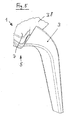
- the transverse beam for a motor vehicle illustrated in FIG. 1 in a perspective view comprises a first section 1 which lies on the driver's side, a second section 2 which lies on the passenger side and which is connected to the first section 1, a first tunnel support 3 on the driver's side and a second tunnel support 4 on the passenger side.
- the first portion 1 of the cross member is connected at its left, outer end with the A-pillar (not shown in the drawing) on the driver side of the motor vehicle. At its right, inner end, the first section 1 of the cross member is connected to the left, inner end of the second section 2 and to the upper end of the first tunnel support 3.
- the first portion 1 of the cross member is formed of two half-shells 5, 6, which are interconnected, namely welded, as shown in FIGS. 1, 2 and 3 can be seen.
- the half shells 5, 6, which are made of metal, form a box section.
- the rear, the vehicle interior facing half-shell 5 has an L-shaped cross section, wherein the longer leg 7 extends substantially vertically and the shorter leg 8 at the lower end of the longer leg 7 to form a rounding 9 by about 90 ° to the front folded.
- the rear half-shell 5 has at the upper end of its longer leg 7 by about 45 ° to the rear bent flange 10.
- the shorter leg 8 has at its front end a bent by about 45 ° down flange 11.
- the profile of the front half-shell 6 is also L-shaped, with a longer leg 12 which is vertical and substantially parallel to the longer leg 7 of the rear half-shell 5, and with a shorter leg 13, at the upper end of the longer leg 12 below Forming a rounding 14 is bent by about 90 ° to the rear.
- the longer leg 12 is provided at its lower end with a beveled by about 45 ° forward flange 15. At the rear End of the shorter leg 13 is provided with a beveled by about 45 ° upwardly flange 16.
- the half shells 5, 6 are welded at their flanges 10, 16 and 11, 15 to form a box section. They could also be glued or riveted.
- an insertion part 17 is inserted.
- an opening is provided in the longer leg 7 of the rear half-shell 5, which has a square shape and into which the insertion part 17 can be inserted.
- the insertion part 17 comprises four equally sized side walls 18, which form a square with rounded corners, which is slightly smaller than the square opening in the longer leg 7th
- the side surfaces 18 are bent at their rear ends to form rounded portions 19 and adjoining flanges 20 by approximately 90 ° in each case to the outside.
- the front ends of the side walls 18 are bent to form rounding 21 and adjoining flanges 22 by about 90 ° in each case inwardly.
- the ends of the flanges 22 are aligned with the outline of a square opening 23 in the longer leg 12 of the front half-shell. 6
- the flanges 20 are welded to the edge regions of the longer leg 7 surrounding the opening in the longer leg 7 of the rear half shell 5. They could also be glued or riveted.
- the flanges 22 of the insertion part 17 are welded to the lying on the rear side, the opening 23 surrounding edge regions of the longer leg 12 of the front half-shell 6. They could also be glued or riveted.
- the inner ends of the flanges 22 form a square opening 24 which is congruent with the opening 23 in the longer leg 12 of the front half-shell 6.
- 24 components can be passed, for example, one or more cables or an air duct.
- the insertion part 17 offers this Way the possibility of a cable or air duct installation by the cross member or its first section. 1
- the insertion part 17 rests on its rear side in the vehicle direction with the flanges 20 from the outside to the half-shells, namely on the half-shell 5. It is on the other, in the vehicle direction front side of the inside of the half-shells, namely the half-shell 6 at.
- the insertion part 17 can be easily joined and connected to the box profile formed by the half-shells 5, 6.
- the second portion 2 of the cross member has in the manner shown in FIGS. 1 and 4 on a Rollformprofil, which is rectangular and consists of two larger, vertical legs 25, 26 and two smaller, horizontal legs 27, 28, which have rounded 29th with the larger legs 25, 26 are connected.
- a Rollformprofil which is rectangular and consists of two larger, vertical legs 25, 26 and two smaller, horizontal legs 27, 28, which have rounded 29th with the larger legs 25, 26 are connected.
- an undercut 30 is rolled, which has the shape of a dovetail with rounded corners. It serves to receive a clip system 31.
- the clip system 31 comprises a connecting part 32 which extends into the undercut 30 and whose outer circumference is smaller than the input opening of the undercut, and a latching part 33 whose outer circumference or at least parts thereof are larger than the input opening of the undercut 30, wherein outer parts of the Verrastungsteils 33 are elastically pressed inwards so that the Verrastungsteil 33 can pass through the input opening of the undercut 30.
- the latching part 33 may have an insertion bevel 34 at its outer end facing the undercut 30. It may also have an insertion bevel 35 on the opposite side, so that it can be pulled out of the undercut 30 again with a corresponding force.
- the latching part 33 may also be designed in such a way that it hooked in the undercut 30 and can not be pulled out by a corresponding application of force (not shown in the drawing).
- the arrangement may be made such that the latching member 30 can be pressed by a tool and/holbar from the undercut 30.
- An attachment of the motor vehicle is connected to the other end of the connecting part 32 of the clip system 31.
- this is a wiring harness 36.
- the Rollformprofil the second portion 2 of the cross member is designed as a constant profile.
- the shape and size of the profile is thus the same over the entire length of the second section.
- the Rollformprofil is formed into a hollow profile and welded. It is preferably laser-welded directly in the roll-forming process.
- the rolled undercut 30 is used to hold the clip system 31. However, it is also possible to attach one or more attachments in the undercut 30 directly.
- the roll forming profile of the second section 2 is bent in the manner shown in FIG. 1. This bending takes place subsequently, ie after the production of the rollform profile.
- the first section 1 facing the end of the second portion 2, which is located in the center of the vehicle is bent upwards, so that an elevated portion 37 is formed, which is bent back at its end facing the first portion 1 back down.
- the Rollformprofil of the second portion 2 is inextricably connected in an overlap region 38 with the first portion 1 of the cross member, preferably welded.
- the half-shells 5, 6 of the first section 1 enclose the Rollformprofil the second portion 2 wholly or partially.
- the first tunnel support 3 is connected to the half-shells 5, 6 of the first section 1. It is permanently connected to these half-shells 5, 6, namely welded. The connection lies in the region of the overlap region 38.
- the first tunnel support 3 is manufactured by an internal pressure forming process.
- the cross section of the first tunnel support 3 becomes larger toward the first section 1 of the cross member extending substantially in the horizontal direction.
- the connection The substantially horizontally extending portions 1, 2 to the tunnel is thus effected by a discontinuous profile, namely the profile of the first tunnel support 3, which in the upper region in which it is connected to the half-shells 5, 6 of the first section 1, a significantly enlarged Cross section has.
- the first tunnel support 3 serves to connect the first and second sections 1, 2 extending essentially in the horizontal direction to the tunnel of the motor vehicle.
- the cross-sectional enlargement of the first tunnel support 3 is produced by the manufacturing method, namely, the internal pressure forming method by which the first tunnel support 3 is manufactured.
- the first tunnel support 3 is connected by punched holes or attached nuts to the bottom area (not shown in the drawing). It is in its upper end to the outside, in the exemplary embodiment so the driver side, bent.
- the second tunnel support 4 is made of a bent tube.
- the tube has a square profile. It is bent in the upper end region in the vehicle direction to the front and connected to the second section 2 of the cross member.
- the bent square tube of the second tunnel support 4 has at its lower end a depressed end portion 39 for tunnel fastening.
- the cross member forms a connection in the motor vehicle between the connection points of the A-pillars on the right and left side of the body and the tunnel area. It serves to accommodate instrument panel and attachments in the cockpit.
- the support structure is formed from the first section 1 on the driver side and the second section 2 on the passenger side.
- the connection to the tunnel is made by a produced in the internal pressure forming process profile on the driver's side, which forms the first tunnel support 3, and a curved square tube on the passenger side, which forms the second tunnel support 4.
Landscapes
- Engineering & Computer Science (AREA)
- Mechanical Engineering (AREA)
- Chemical & Material Sciences (AREA)
- Combustion & Propulsion (AREA)
- Transportation (AREA)
- Body Structure For Vehicles (AREA)
Abstract
Description
- Die Erfindung betrifft einen Querträger für ein Kraftfahrzeug.
- Ein derartiger Querträger ist aus der DE 102 21 654 A1 bekannt. Er dient dazu, die A-Säulen oder andere Bauteile an den Seiten eines Kraftfahrzeugs miteinander zu verbinden. Der Querträger kann zusätzlich mit dem Tunnel und/oder der Stirnwand verbunden sein.
- Aus der EP 0 990 578 A2 ist ein Querträger für ein Kraftfahrzeug bekannt, der zumindest zwei in axialer Verlängerung angeordnete Profilabschnitte unterschiedlichen Querschnitts aufweist, die über eine Teillänge überlappend angeordnet sind. Die Profilabschnitte sind im Überlappungsbereich durch ein stabilisierendes Verbindungsteil miteinander verbunden.
- Aufgabe der Erfindung ist es, einen verbesserten Querträger für ein Kraftfahrzeug vorzuschlagen.
- Gemäß der Erfindung wird diese Aufgabe durch die Merkmale des Anspruchs 1 gelöst. Ein Abschnitt des Querträgers ist aus zwei Halbschalen gebildet, die miteinander verbunden sind. Dieser Abschnitt befindet sich vorzugsweise auf der Fahrerseite des Kraftfahrzeugs. Die Halbschalen sind vorzugsweise aus Metall. Sie sind vorzugsweise miteinander verschweißt, insbesondere Mag- oder Lasergeschweißt, können aber auch auf andere Weise miteinander verbunden, beispielsweise miteinander verklebt oder vernietet sein. Der Querträger kann zur Aufnahme der Längssäule, von Befestigungselementen und/oder Anbauteilen dienen.
- Vorteilhafte Weiterbildungen sind in den Unteransprüchen beschrieben.
- Die Halbschalen bilden vorzugsweise ein Kastenprofil. Hierdurch wird die Stabilität, insbesondere die Verwindungssteifigkeit des Querträgers erhöht.
- Vorzugsweise ist in dem Querträger ein Einschubteil eingefügt. Das Einschubteil ist vorzugsweise aus Metall. Durch das Einschubteil kann insbesondere ein Durchbruch in dem Querträger geschaffen werden, insbesondere für Komponenten im Cockpit des Kraftfahrzeugs, beispielsweise für eine Kabelverlegung und/oder Luftkanalverlegung.
- Eine weitere vorteilhafte Weiterbildung ist dadurch gekennzeichnet, daß das Einschubteil mit den Halbschalen fest verbunden ist. Insbesondere ist das Einschubteil mit den Halbschalen verschweißt. Es kann aber auch auf andere Weise mit den Halbschalen verbunden, insbesondere verklebt oder vernietet sein.
- Vorteilhaft ist es, wenn das Einschubteil Flansche aufweist. Die Flansche befinden sich vorzugsweise auf beiden Seiten des Einschubteils.
- Vorzugsweise sind die Flansche mit den Halbschalen verbunden. Die Verbindung erfolgt vorzugsweise durch Verschweißen. Es sind dabei auch andere Verbindungsarten möglich, wie beispielsweise Verkleben oder Vernieten.
- Eine weitere vorteilhafte Weiterbildung ist dadurch gekennzeichnet, daß das Einschubteil auf einer Seite von außen und auf der anderen Seite von innen an den Halbschalen anliegt. Hierdurch kann das Einschubteil auf besonders einfache Weise mit den Halbschalen bzw. mit dem von den Halbschalen gebildeten Kastenprofil gefügt und verbunden werden. Dies ist besonders dann vorteilhaft, wenn das Einschubteil Flansche aufweist.
- Eine weitere vorteilhafte Weiterbildung ist dadurch gekennzeichnet, daß ein Abschnitt des Querträgers ein Rollformprofil (Walzprofil) aufweist. Dieser Abschnitt befindet sich vorzugsweise auf der Beifahrerseite des Kraftfahrzeugs. Vorteilhaft ist es, wenn es sich um ein konstantes Rollformprofil handelt. Das Rollformprofil ist vorzugsweise als Hohlprofil ausgestaltet. Rollformprofile können preiswert hergestellt werden.
- Vorteilhaft ist es, wenn das Rollformprofil zu einem Hohlprofil geformt und verschweißt ist. Hierbei ist es von besonderem Vorteil, wenn das Rollformprofil im Rollformprozeß lasergeschweißt ist.
- Das Rollformprofil weist vorzugsweise einen Hinterschnitt auf, der vorzugsweise eingewalzt ist. Der Hinterschnitt ist vorzugsweise auf der Rückseite des Rollformprofils vorgesehen. Er kann zur direkten Befestigung von Anbauteilen dienen oder zur Aufnahme eines Clipsystems für Anbauteile. Insbesondere kann durch den Hinterschnitt ein Kabelbaum an dem Rollformprofil befestigt werden. Rollformprofile geben die Möglichkeit, Hinterschnitte im Querschnitt zu fertigen. Dies kann annähernd kostenneutral erfolgen.
- Das Rollformprofil kann gebogen sein. Vorzugsweise ist es nachträglich gebogen.
- Eine vorteilhafte Weiterbildung ist dadurch gekennzeichnet, daß das Rollformprofil mit den Halbschalen unlösbar verbunden ist. Vorzugsweise ist das Rollformprofil mit den Halbschalen verschweißt. Es kann aber auch auf andere Weise mit den Halbschalen verbunden, insbesondere verklebt oder vernietet sein.
- Vorzugsweise umschließen die Halbschalen das Rollformprofil ganz oder teilweise.
- Eine weitere vorteilhafte Weiterbildung ist dadurch gekennzeichnet, daß der Querträger eine innendruckumgeformte Tunnelstütze aufweist. Innendruckumgeformte Bauteile gewährleisten einen optimalen Kraftfluß. Dieser kann zur Abstützung im Bodenbereich des Fahrzeugs ausgenutzt werden. Ein Verfahren zum Herstellen eines innendruckumgeformten Bauteils ist aus der DE 199 15 381 A1, auf die Bezug genommen wird, bekannt.
- Der Querschnitt der Tunnelstütze wird vorzugsweise zu einem horizontal verlaufenden Abschnitt des Querträgers hin größer.
- Eine weitere vorteilhafte Weiterbildung ist dadurch gekennzeichnet, daß der Querträger eine Tunnelstütze aus einem gebogenen Rohr, vorzugsweise einem gebogenen Vierkantrohr, aufweist.
- Durch steigende Anforderungen an den Komfort wird durch zusätzliche Komponenten der Bauraum in einem Fahrzeug-Cockpit immer enger. Gleichzeitig werden die Anforderungen an die Stabilität der tragenden Bauteile immer höher, inbesondere die Anforderungen hinsichtlich des Schwingungsverhaltens und des Crashverhaltens. Die vorliegende Erfindung bietet eine technische Lösung für diese gegenläufigen Anforderungen.
- Ein Ausführungsbeispiel der Erfindung wird nachstehend anhand der beigefügten Zeichnung im einzelnen erläutert. In der Zeichnung zeigt
- Fig. 1
- einen Querträger für ein Kraftfahrzeug in einer perspektivischen Ansicht,
- Fig. 2
- einen Querschnitt durch den auf der Fahrerseite liegenden Abschnitt des Querträgers gemäß Fig. 1,
- Fig. 3
- einen vergrößerten Ausschnitt aus der Fig. 2,
- Fig. 4
- einen Querschnitt durch den auf der Beifahrerseite liegenden Abschnitt des Querträgers gemäß Fig. 1 und
- Fig. 5
- die auf der Fahrerseite des Querträgers gemäß Fig. 1 liegende Tunnelstütze in einer vergrößerten Ansicht.
- Der in Fig. 1 in einer perspektivischen Ansicht dargestellte Querträger für ein Kraftfahrzeug umfaßt einen ersten Abschnitt 1, der auf der Fahrerseite liegt, einen zweiten Abschnitt 2, der auf der Beifahrerseite liegt und der mit dem ersten Abschnitt 1 verbunden ist, eine erste Tunnelstütze 3 auf der Fahrerseite und eine zweite Tunnelstütze 4 auf der Beifahrerseite.
- Der erste Abschnitt 1 des Querträgers wird an seinem linken, äußeren Ende mit der A-Säule (in der Zeichnung nicht dargestellt) auf der Fahrerseite des Kraftfahrzeugs verbunden. An seinem rechten, inneren Ende ist der erste Abschnitt 1 des Querträgers mit dem linken, inneren Ende des zweiten Abschnitts 2 und mit dem oberen Ende der ersten Tunnelstütze 3 verbunden.
- Der erste Abschnitt 1 des Querträgers ist aus zwei Halbschalen 5, 6 gebildet, die miteinander verbunden, nämlich verschweißt, sind, wie aus Fig. 1, 2 und 3 ersichtlich. Die Halbschalen 5, 6, die aus Metall sind, bilden ein Kastenprofil. Die hintere, dem Fahrzeug-Innenraum zugewandte Halbschale 5 weist einen L-förmigen Querschnitt auf, wobei der längere Schenkel 7 im wesentlichen vertikal verläuft und der kürzere Schenkel 8 am unteren Ende des längeren Schenkels 7 unter Bildung einer Abrundung 9 um etwa 90° nach vorne abgekantet ist. Die hintere Halbschale 5 weist am oberen Ende ihres längeren Schenkels 7 einen um etwa 45° nach hinten abgekanteten Flansch 10 auf. Der kürzere Schenkel 8 weist an seinem vorderen Ende einen um etwa 45° nach unten abgekanteten Flansch 11 auf.
- Das Profil der vorderen Halbschale 6 ist ebenfalls L-förmig, mit einem längeren Schenkel 12, der vertikal und im wesentlichen parallel zum längeren Schenkel 7 der hinteren Halbschale 5 verläuft, und mit einem kürzeren Schenkel 13, der am oberen Ende des längeren Schenkels 12 unter Bildung einer Abrundung 14 um etwa 90° nach hinten abgekantet ist. Der längere Schenkel 12 ist an seinem unteren Ende mit einem um etwa 45° nach vorne abgekanteten Flansch 15 versehen. Am hinteren Ende des kürzeren Schenkels 13 ist ein um etwa 45° nach oben abgekanteter Flansch 16 vorgesehen.
- Die Halbschalen 5, 6 sind an ihren Flanschen 10, 16 und 11, 15 unter Bildung eines Kastenprofils verschweißt. Sie könnten auch verklebt oder vernietet sein.
- In den ersten Abschnitt 1 des Querträgers ist ein Einschubteil 17 eingefügt. Zum Einfügen des Einschubteils 17 ist in den längeren Schenkel 7 der hinteren Halbschale 5 eine Öffnung vorgesehen, die eine quadratische Form aufweist und in die das Einschubteil 17 eingesetzt werden kann. Das Einschubteil 17 umfaßt vier jeweils gleich große Seitenwände 18, die ein Quadrat mit abgerundeten Ecken bilden, das etwas kleiner ist als die quadratische Öffnung in dem längeren Schenkel 7.
- Die Seitenflächen 18 sind an ihren hinteren Enden unter Bildung von Abrundungen 19 und daran anschließenden Flanschen 20 um etwa 90° jeweils nach außen abgekantet. Die vorderen Enden der Seitenwände 18 sind unter Bildung von Abrundungen 21 und daran anschließenden Flanschen 22 um etwa 90° jeweils nach innen abgekantet. Die Enden der Flansche 22 fluchten mit dem Umriß einer quadratischen Öffnung 23 in dem längeren Schenkel 12 der vorderen Halbschale 6.
- Die Flansche 20 sind mit den die Öffnung in dem längeren Schenkel 7 der hinteren Halbschale 5 umgebenden Randbereichen des längeren Schenkels 7 verschweißt. Sie könnten auch verklebt oder vernietet sein. Die Flansche 22 des Einschubteils 17 sind mit den auf der hinteren Seite liegenden, die Öffnung 23 umgebenden Randbereichen des längeren Schenkels 12 der vorderen Halbschale 6 verschweißt. Sie könnten auch verklebt oder vernietet sein.
- Die inneren Enden der Flansche 22 bilden eine quadratische Öffnung 24, die mit der Öffnung 23 im längeren Schenkel 12 der vorderen Halbschale 6 kongruent ist. Durch die Öffnungen 23, 24 können Bauteile hindurchgeführt werden, beispielsweise eines oder mehrere Kabel oder ein Luftkanal. Das Einschubteil 17 bietet auf diese Weise die Möglichkeit einer Kabel- oder Luftkanalverlegung durch den Querträger bzw. dessen ersten Abschnitt 1.
- Das Einschubteil 17 liegt auf seiner in Fahrzeugrichtung hinteren Seite mit den Flanschen 20 von außen an den Halbschalen an, nämlich an der Halbschale 5. Es liegt auf der anderen, in Fahrzeugrichtung vorderen Seite von innen an den Halbschalen, nämlich der Halbschale 6 an. Durch diese Ausgestaltung kann das Einschubteil 17 auf einfache Weise mit dem von den Halbschalen 5, 6 gebildeten Kastenprofil gefügt und verbunden werden.
- Der zweite Abschnitt 2 des Querträgers weist in der aus Fig. 1 und 4 ersichtlichen Weise eine Rollformprofil auf, das rechteckig ausgebildet ist und aus zwei größeren, vertikalen Schenkeln 25, 26 und zwei kleineren, horizontalen Schenkeln 27, 28 besteht, die über Abrundungen 29 mit den größeren Schenkeln 25, 26 verbunden sind. In den hinteren größeren Schenkel 26 ist ein Hinterschnitt 30 eingewalzt, der die Form eines Schwalbenschwanzes mit abgerundeten Ecken aufweist. Er dient zur Aufnahme eines Clipsystems 31. Das Clipsystem 31 umfaßt ein Verbindungsteil 32, das sich in den Hinterschnitt 30 hineinerstreckt und dessen Außenumfang kleiner ist als die Eingangsöffnung des Hinterschnitts, und ein Verrastungsteil 33, dessen Außenumfang oder zumindest Teile davon größer sind als die Eingangsöffnung des Hinterschnitts 30, wobei äußere Teile des Verrastungsteils 33 elastisch nach innen eindrückbar sind, so daß das Verrastungsteil 33 die Eingangsöffnung des Hinterschnitts 30 durchschreiten kann. Das Verrastungsteil 33 kann an seinem äußeren, dem Hinterschnitt 30 zugewandten Ende eine Einführschräge 34 aufweisen. Es kann auf der gegenüberliegenden Seite ebenfalls eine Einführschräge 35 aufweisen, so daß es mit einer entsprechenden Kraft wieder aus dem Hinterschnitt 30 herausgezogen werden kann. Das Verrastungsteil 33 kann allerdings auch in der Weise ausgestaltet sein, daß es sich in dem Hinterschnitt 30 verhakt und nicht durch eine entsprechende Kraftaufwendung herausgezogen werden kann (in der Zeichnung nicht dargestellt). In diesem Fall kann die Anordnung derart getroffen sein, daß das Verrastungsteil 30 durch ein Werkzeug eindrückbar und aus dem Hinterschnitt 30 herausholbar ist.
- Mit dem anderen Ende des Verbindungsteils 32 des Clipsystems 31 ist ein Anbauteil des Kraftfahrzeugs verbunden. In dem dargestellten Ausführungsbeispiel ist dies ein Kabelbaum 36.
- Das Rollformprofil des zweiten Abschnitts 2 des Querträgers ist als konstantes Profil ausgestaltet. Die Form und Größe des Profils ist also über die gesamte Länge des zweiten Abschnitts gleich. Das Rollformprofil ist zu einem Hohlprofil geformt und verschweißt. Es ist vorzugsweise direkt im Rollformprozeß lasergeschweißt. Der eingewalzte Hinterschnitt 30 dient zur Aufnahme des Clipsystems 31. Es ist allerdings auch möglich, eines oder mehrere Anbauteile in dem Hinterschnitt 30 unmittelbar zu befestigen.
- Das Rollformprofil des zweiten Abschnitts 2 ist in der aus Fig. 1 ersichtlichen Weise gebogen. Diese Biegung erfolgt nachträglich, also nach der Herstellung des Rollformprofils. Das dem ersten Abschnitt 1 zugewandte Ende des zweiten Abschnitts 2, das sich in der Mitte des Fahrzeugs befindet, ist nach oben abgekröpft, so daß ein erhöhter Bereich 37 gebildet wird, der an seinem dem ersten Abschnitt 1 zugewandten Ende wieder nach unten abgekröpft ist.
- Das Rollformprofil des zweiten Abschnitts 2 ist in einem Überlappungsbereich 38 mit dem ersten Abschnitt 1 des Querträgers unlösbar verbunden, vorzugsweise verschweißt. Um Überlappungsbereich 38 umschließen die Halbschalen 5, 6 des ersten Abschnitts 1 das Rollformprofil des zweiten Abschnitts 2 ganz oder teilweise.
- Die erste Tunnelstütze 3 ist mit den Halbschalen 5, 6 des ersten Abschnitts 1 verbunden. Sie ist mit diesen Halbschalen 5, 6 unlösbar verbunden, nämlich verschweißt. Die Verbindung liegt im Bereich des Überlappungsbereichs 38.
- Die erste Tunnelstütze 3 ist durch ein Innendruck-Umformverfahren hergestellt. Der Querschnitt der ersten Tunnelstütze 3 wird zu dem im wesentlichen in horizontaler Richtung verlaufenden ersten Abschnitt 1 des Querträgers hin größer. Die Anbindung der im wesentlichen horizontal verlaufenden Abschnitte 1, 2 zum Tunnel erfolgt demnach durch ein diskontinuierliches Profil, nämlich das Profil der ersten Tunnelstütze 3, welches im oberen Bereich, in dem es an die Halbschalen 5, 6 des ersten Abschnitts 1 angebunden ist, einen deutlich vergrößerten Querschnitt aufweist. Die erste Tunnelstütze 3 dient zur Verbindung der im wesentlichen in horizontaler Richtung verlaufenden ersten und zweiten Abschnitte 1, 2 mit dem Tunnel des Kraftfahrzeugs. Die Querschnittsvergrößerung der ersten Tunnelstütze 3 wird durch das Herstellungsverfahren erzeugt, nämlich das Innendruck-Umformverfahren, durch das die erste Tunnelstütze 3 hergestellt ist. Die erste Tunnelstütze 3 wird durch eingestanzte Löcher oder aufgesetzte Muttern an den Bodenbereich angebunden (in der Zeichnung nicht dargestellt). Sie ist in ihrem oberen Endbereich nach außen, im Ausführungsbeispiel also zur Fahrerseite hin, gebogen.
- Die zweite Tunnelstütze 4 ist aus einem gebogenen Rohr hergestellt. Das Rohr hat ein Vierkantprofil. Es ist im oberen Endbereich in Fahrzeugrichtung nach vorne gebogen und an den zweiten Abschnitt 2 des Querträgers angebunden. Das gebogene Vierkantrohr der zweiten Tunnelstütze 4 weist an seinem unteren Ende einen verdrückten Endbereich 39 zur Tunnelbefestigung auf.
- Der Querträger bildet eine Verbindung im Kraftfahrzeug zwischen den Anbindepunkten der A-Säulen auf der rechten und linken Seite der Karosserie und dem Tunnelbereich. Er dient zur Aufnahme von Instrumententafel und Anbauteilen im Cockpit. Die Tragstruktur wird aus dem ersten Abschnitt 1 auf der Fahrerseite und dem zweiten Abschnitt 2 auf der Beifahrerseite gebildet. Die Anbindung zum Tunnel erfolgt durch ein im Innendruck-Umformverfahren hergestelltes Profil auf der Fahrerseite, das die erste Tunnelstütze 3 bildet, und ein gebogenes Vierkantrohr auf der Beifahrerseite, das die zweite Tunnelstütze 4 bildet.
Claims (16)
- Querträger für ein Kraftfahrzeug,
dadurch gekennzeichnet,
daß ein Abschnitt (1) des Querträgers aus zwei Halbschalen (5, 6) gebildet ist, die miteinander verbunden sind. - Querträger nach Anspruch 1, dadurch gekennzeichnet, daß die Halbschalen (5, 6) ein Kastenprofil bilden.
- Querträger nach Anspruch 1 oder 2, dadurch gekennzeichnet, daß in den Querträger ein Einschubteil (17) eingefügt ist.
- Querträger nach Anspruch 3, dadurch gekennzeichnet, daß das Einschubteil (17) mit den Halbschalen (5, 6) fest verbunden ist.
- Querträger nach Anspruch 3 oder 4, dadurch gekennzeichnet, daß das Einschubteil (17) Flansche (20, 22) aufweist.
- Einschubteil nach Anspruch 5, dadurch gekennzeichnet, daß die Flansche (20, 22) mit den Halbschalen (5, 6) verbunden sind.
- Querträger nach einem der Ansprüche 3 bis 6, dadurch gekennzeichnet, daß das Einschubteil (17) auf einer Seite von außen und auf der anderen Seite von innen an den Halbschalen (5, 6) anliegt.
- Querträger nach einem der vorhergehenden Ansprüche, dadurch gekennzeichnet, daß ein Abschnitt (2) des Querträgers ein Rollformprofil aufweist.
- Querträger nach Anspruch 8, dadurch gekennzeichnet, daß das Rollformprofil zu einem Hohlprofil geformt und verschweißt ist.
- Querträger nach Anspruch 8 oder 9, dadurch gekennzeichnet, daß das Rollformprofil einen vorzugsweise eingewalzten Hinterschnitt (30) aufweist.
- Querträger nach einem der Ansprüche 8 bis 10, dadurch gekennzeichnet, daß das Rollformprofil gebogen ist.
- Querträger nach einem der Ansprüche 8 bis 11, dadurch gekennzeichnet, daß das Rollformprofil (2) mit den Halbschalen (5, 6) unlösbar verbunden ist.
- Querträger nach einem der Ansprüche 8 bis 12, dadurch gekennzeichnet, daß die Halbschalen (5, 6) das Rollformprofil ganz oder teilweise umschließen.
- Querträger nach einem der vorhergehenden Ansprüche, dadurch gekennzeichnet, daß der Querträger eine innendruckumgeformte Tunnelstütze (3) aufweist.
- Querträger nach Anspruch 14, dadurch gekennzeichnet, daß der Querschnitt der Tunnelstütze (3) zu einem horizontal verlaufenden Abschnitt (1) des Querträgers hin größer wird.
- Querträger nach einem der vorhergehenden Ansprüche, dadurch gekennzeichnet, daß der Querträger eine Tunnelstütze (4) aus einem gebogenen Rohr, vorzugsweise einem gebogenen Vierkantrohr, aufweist.
Priority Applications (1)
| Application Number | Priority Date | Filing Date | Title |
|---|---|---|---|
| EP08010466A EP1977960B1 (de) | 2004-07-15 | 2005-07-13 | Querträger für ein Kraftfahrzeug |
Applications Claiming Priority (1)
| Application Number | Priority Date | Filing Date | Title |
|---|---|---|---|
| DE200420011120 DE202004011120U1 (de) | 2004-07-15 | 2004-07-15 | Querträger für ein Kraftfahrzeug |
Related Child Applications (1)
| Application Number | Title | Priority Date | Filing Date |
|---|---|---|---|
| EP08010466A Division EP1977960B1 (de) | 2004-07-15 | 2005-07-13 | Querträger für ein Kraftfahrzeug |
Publications (3)
| Publication Number | Publication Date |
|---|---|
| EP1616776A2 true EP1616776A2 (de) | 2006-01-18 |
| EP1616776A3 EP1616776A3 (de) | 2006-12-13 |
| EP1616776B1 EP1616776B1 (de) | 2008-10-22 |
Family
ID=35169279
Family Applications (2)
| Application Number | Title | Priority Date | Filing Date |
|---|---|---|---|
| EP20050015249 Active EP1616776B1 (de) | 2004-07-15 | 2005-07-13 | Querträger für ein Kratffahrzeug |
| EP08010466A Expired - Fee Related EP1977960B1 (de) | 2004-07-15 | 2005-07-13 | Querträger für ein Kraftfahrzeug |
Family Applications After (1)
| Application Number | Title | Priority Date | Filing Date |
|---|---|---|---|
| EP08010466A Expired - Fee Related EP1977960B1 (de) | 2004-07-15 | 2005-07-13 | Querträger für ein Kraftfahrzeug |
Country Status (3)
| Country | Link |
|---|---|
| EP (2) | EP1616776B1 (de) |
| DE (3) | DE202004011120U1 (de) |
| ES (2) | ES2314523T3 (de) |
Cited By (1)
| Publication number | Priority date | Publication date | Assignee | Title |
|---|---|---|---|---|
| CN114475807A (zh) * | 2022-02-22 | 2022-05-13 | 重庆长安新能源汽车科技有限公司 | 镁铝合金转向支撑横梁总成 |
Families Citing this family (7)
| Publication number | Priority date | Publication date | Assignee | Title |
|---|---|---|---|---|
| DE202006020855U1 (de) * | 2006-09-01 | 2010-09-02 | Audi Ag | Befestigungsanordnung einer Haltekonsole an einem Trägerteil einer Kraftwagenkarosserie |
| DE102007041698A1 (de) * | 2007-09-03 | 2009-03-05 | GM Global Technology Operations, Inc., Detroit | Bauteil in Schalenbauweise |
| DE102008049762A1 (de) | 2008-09-30 | 2010-04-01 | GM Global Technology Operations, Inc., Detroit | Vorderbau für ein Kraftfahrzeug |
| DE102009021964A1 (de) * | 2009-05-19 | 2010-11-25 | Audi Ag | Hohlprofil für eine Fahrzeugkarosserie |
| EP3871627B1 (de) | 2020-02-27 | 2024-05-01 | Erbe Elektromedizin GmbH | Chirurgische einrichtung und steuerverfahren für diese |
| DE102020131386A1 (de) | 2020-11-26 | 2022-06-02 | Benteler Automobiltechnik Gmbh | Querträgeranordnung in einem Fahrzeug |
| DE102022113436A1 (de) | 2022-05-27 | 2023-11-30 | Kirchhoff Automotive Deutschland Gmbh | Instrumententafelträger |
Citations (3)
| Publication number | Priority date | Publication date | Assignee | Title |
|---|---|---|---|---|
| EP0990578A2 (de) | 1998-10-01 | 2000-04-05 | Progress-Werk Oberkirch Aktiengesellschaft | Verfahren zum Herstellen eines Querträgers sowie derartiger Querträger |
| DE19915381A1 (de) | 1999-04-06 | 2000-10-26 | Peter Amborn | Verfahren zum Herstellen eines rohrartigen Strukturelements |
| DE10221654A1 (de) | 2001-10-01 | 2003-04-24 | Dura Automotive Plettenberg | Querträger für ein Kraftfahrzeug |
Family Cites Families (6)
| Publication number | Priority date | Publication date | Assignee | Title |
|---|---|---|---|---|
| DE19933533A1 (de) * | 1999-07-16 | 2001-01-18 | Bayerische Motoren Werke Ag | Luftleitsystem für ein Kraftfahrzeug |
| DE10124248A1 (de) * | 2001-05-18 | 2002-11-21 | Alusuisse Tech & Man Ag | Verbindungselement für Hohlprofile unterschiedlichen Querschnittes |
| DE10258880A1 (de) * | 2002-12-17 | 2004-07-15 | Volkswagen Ag | Vorrichtung zur Befestigung eines Montageteils an einem tragenden Bauteil |
| DE102005010161A1 (de) * | 2004-03-02 | 2006-05-24 | Behr Gmbh & Co. Kg | Bauteil für einen Träger eines Fahrzeugs |
| DE102005011331A1 (de) * | 2004-03-19 | 2005-10-13 | Behr Gmbh & Co. Kg | Querträger mit integrierter Luftführung für ein Kraftfahrzeug |
| WO2005092649A1 (de) * | 2004-03-19 | 2005-10-06 | Behr Gmbh & Co. Kg | Querträger mit integrierter luftführung für ein kraftfahrzeug |
-
2004
- 2004-07-15 DE DE200420011120 patent/DE202004011120U1/de not_active Expired - Lifetime
-
2005
- 2005-07-13 EP EP20050015249 patent/EP1616776B1/de active Active
- 2005-07-13 DE DE200550010431 patent/DE502005010431D1/de active Active
- 2005-07-13 ES ES05015249T patent/ES2314523T3/es active Active
- 2005-07-13 ES ES08010466T patent/ES2354534T3/es active Active
- 2005-07-13 EP EP08010466A patent/EP1977960B1/de not_active Expired - Fee Related
- 2005-07-13 DE DE200550005734 patent/DE502005005734D1/de active Active
Patent Citations (3)
| Publication number | Priority date | Publication date | Assignee | Title |
|---|---|---|---|---|
| EP0990578A2 (de) | 1998-10-01 | 2000-04-05 | Progress-Werk Oberkirch Aktiengesellschaft | Verfahren zum Herstellen eines Querträgers sowie derartiger Querträger |
| DE19915381A1 (de) | 1999-04-06 | 2000-10-26 | Peter Amborn | Verfahren zum Herstellen eines rohrartigen Strukturelements |
| DE10221654A1 (de) | 2001-10-01 | 2003-04-24 | Dura Automotive Plettenberg | Querträger für ein Kraftfahrzeug |
Cited By (1)
| Publication number | Priority date | Publication date | Assignee | Title |
|---|---|---|---|---|
| CN114475807A (zh) * | 2022-02-22 | 2022-05-13 | 重庆长安新能源汽车科技有限公司 | 镁铝合金转向支撑横梁总成 |
Also Published As
| Publication number | Publication date |
|---|---|
| DE502005005734D1 (de) | 2008-12-04 |
| EP1977960A1 (de) | 2008-10-08 |
| EP1616776A3 (de) | 2006-12-13 |
| ES2314523T3 (es) | 2009-03-16 |
| DE202004011120U1 (de) | 2005-11-24 |
| DE502005010431D1 (de) | 2010-12-02 |
| EP1977960B1 (de) | 2010-10-20 |
| ES2354534T3 (es) | 2011-03-15 |
| EP1616776B1 (de) | 2008-10-22 |
Similar Documents
| Publication | Publication Date | Title |
|---|---|---|
| EP1977960B1 (de) | Querträger für ein Kraftfahrzeug | |
| DE60220110T2 (de) | Verfahren zum Herstellen einer Fahrzeugrahmenanordnung mit kastenförmigem Knautschteil | |
| DE10220025A1 (de) | Querträger | |
| DE102007014116A1 (de) | Säule als Teil einer Karosseriestruktur eines Kraftwagens | |
| DE102010043165B4 (de) | Aggregatlager mit integrierten Wegbegrenzern und Verfahren zur Fertigung | |
| DE102007038036A1 (de) | Verfahren zur Herstellung eines rohrförmigen Tragprofils für einen Instrumententräger | |
| DE102009048335A1 (de) | Sitzquerträger für Karosserieunterboden | |
| DE102009049872B4 (de) | Pralldämpferaufnahme für eine Karosseriestruktur eines Kraftfahrzeugs | |
| DE102009026299A9 (de) | Cockpitquerträger für ein Kraftfahrzeug | |
| DE102015203309A1 (de) | Fahrzeug-Karosseriestruktur | |
| EP2508407A1 (de) | Gerüst, insbesondere für elektrische Einrichtungen in einem Schienenfahrzeug, und Verfahren zur Herstellung des Gerüsts | |
| DE102014211534B4 (de) | Verfahren zur Herstellung von Fahrzeugkarosserien | |
| DE102015100195B4 (de) | Befestigungsanordnung eines Seitenwandelements an einem inneren Strukturelement einer Karosserie eines Personenkraftwagens | |
| DE102005031728A1 (de) | Tragstruktur einer Karosserie und Verfahren zum Herstellen einer derartigen Tragstruktur | |
| DE10359746B4 (de) | Montageträger für eine Instrumententafel | |
| DE102006005023A1 (de) | Instrumententafelträger für ein Kraftfahrzeug | |
| DE102020209298A1 (de) | Karosserie für ein Fahrzeug | |
| DE102019106154A1 (de) | Batteriewanne, Batteriewannenanordnung und Verfahren zur Herstellung einer Batteriewanne | |
| EP1544085A2 (de) | Querträger eines Fahrzeugs, insbesondere Hybridquerträger | |
| DE10231864A1 (de) | Karosserie-Blechbauteil und Verfahren zu seiner Herstellung | |
| DE10360045A1 (de) | Hybridquerträger | |
| DE102004029278B4 (de) | Tragstruktur für ein Kraftfahrzeug | |
| DE102018008798A1 (de) | Befestigungsanordnung eines Energieabsorptionselements an einem Längsträger für ein Kraftfahrzeug sowie Energieabsorptionselement für einen Längsträger eines Kraftfahrzeugs | |
| DE102022120872B3 (de) | Instrumententafelträger | |
| DE19860030A1 (de) | Fahrzeugstruktur mit Schwellern und vorderen Längsträgern |
Legal Events
| Date | Code | Title | Description |
|---|---|---|---|
| PUAI | Public reference made under article 153(3) epc to a published international application that has entered the european phase |
Free format text: ORIGINAL CODE: 0009012 |
|
| AK | Designated contracting states |
Kind code of ref document: A2 Designated state(s): AT BE BG CH CY CZ DE DK EE ES FI FR GB GR HU IE IS IT LI LT LU LV MC NL PL PT RO SE SI SK TR |
|
| AX | Request for extension of the european patent |
Extension state: AL BA HR MK YU |
|
| 17P | Request for examination filed |
Effective date: 20060104 |
|
| PUAL | Search report despatched |
Free format text: ORIGINAL CODE: 0009013 |
|
| AK | Designated contracting states |
Kind code of ref document: A3 Designated state(s): AT BE BG CH CY CZ DE DK EE ES FI FR GB GR HU IE IS IT LI LT LU LV MC NL PL PT RO SE SI SK TR |
|
| AX | Request for extension of the european patent |
Extension state: AL BA HR MK YU |
|
| 17Q | First examination report despatched |
Effective date: 20070111 |
|
| AKX | Designation fees paid |
Designated state(s): CZ DE ES FR GB IT |
|
| GRAP | Despatch of communication of intention to grant a patent |
Free format text: ORIGINAL CODE: EPIDOSNIGR1 |
|
| GRAS | Grant fee paid |
Free format text: ORIGINAL CODE: EPIDOSNIGR3 |
|
| RAP1 | Party data changed (applicant data changed or rights of an application transferred) |
Owner name: DURA AUTOMOTIVE BODY & GLASS SYSTEMS GMBH |
|
| GRAA | (expected) grant |
Free format text: ORIGINAL CODE: 0009210 |
|
| AK | Designated contracting states |
Kind code of ref document: B1 Designated state(s): CZ DE ES FR GB IT |
|
| REG | Reference to a national code |
Ref country code: GB Ref legal event code: FG4D Free format text: NOT ENGLISH |
|
| REF | Corresponds to: |
Ref document number: 502005005734 Country of ref document: DE Date of ref document: 20081204 Kind code of ref document: P |
|
| REG | Reference to a national code |
Ref country code: ES Ref legal event code: FG2A Ref document number: 2314523 Country of ref document: ES Kind code of ref document: T3 |
|
| PLBE | No opposition filed within time limit |
Free format text: ORIGINAL CODE: 0009261 |
|
| STAA | Information on the status of an ep patent application or granted ep patent |
Free format text: STATUS: NO OPPOSITION FILED WITHIN TIME LIMIT |
|
| PG25 | Lapsed in a contracting state [announced via postgrant information from national office to epo] |
Ref country code: IT Free format text: LAPSE BECAUSE OF FAILURE TO SUBMIT A TRANSLATION OF THE DESCRIPTION OR TO PAY THE FEE WITHIN THE PRESCRIBED TIME-LIMIT Effective date: 20081022 |
|
| 26N | No opposition filed |
Effective date: 20090723 |
|
| PGFP | Annual fee paid to national office [announced via postgrant information from national office to epo] |
Ref country code: ES Payment date: 20120726 Year of fee payment: 8 |
|
| REG | Reference to a national code |
Ref country code: ES Ref legal event code: FD2A Effective date: 20140908 |
|
| PG25 | Lapsed in a contracting state [announced via postgrant information from national office to epo] |
Ref country code: ES Free format text: LAPSE BECAUSE OF NON-PAYMENT OF DUE FEES Effective date: 20130714 |
|
| PGFP | Annual fee paid to national office [announced via postgrant information from national office to epo] |
Ref country code: CZ Payment date: 20150702 Year of fee payment: 11 |
|
| REG | Reference to a national code |
Ref country code: FR Ref legal event code: PLFP Year of fee payment: 12 |
|
| REG | Reference to a national code |
Ref country code: DE Ref legal event code: R082 Ref document number: 502005005734 Country of ref document: DE Representative=s name: LORENZ SEIDLER GOSSEL RECHTSANWAELTE PATENTANW, DE Ref country code: DE Ref legal event code: R081 Ref document number: 502005005734 Country of ref document: DE Owner name: DURA AUTOMOTIVE HOLDINGS U.K., LTD., CASTLE VA, GB Free format text: FORMER OWNER: DURA AUTOMOTIVE BODY & GLASS SYSTEMS GMBH, 58840 PLETTENBERG, DE |
|
| PG25 | Lapsed in a contracting state [announced via postgrant information from national office to epo] |
Ref country code: CZ Free format text: LAPSE BECAUSE OF NON-PAYMENT OF DUE FEES Effective date: 20160713 |
|
| REG | Reference to a national code |
Ref country code: FR Ref legal event code: PLFP Year of fee payment: 13 |
|
| REG | Reference to a national code |
Ref country code: FR Ref legal event code: TP Owner name: DURA AUTOMOTIVE BODY GLASS SYST Effective date: 20170629 |
|
| REG | Reference to a national code |
Ref country code: GB Ref legal event code: 732E Free format text: REGISTERED BETWEEN 20170727 AND 20170802 |
|
| REG | Reference to a national code |
Ref country code: FR Ref legal event code: PLFP Year of fee payment: 14 |
|
| PGFP | Annual fee paid to national office [announced via postgrant information from national office to epo] |
Ref country code: DE Payment date: 20220727 Year of fee payment: 18 |
|
| PGFP | Annual fee paid to national office [announced via postgrant information from national office to epo] |
Ref country code: GB Payment date: 20231227 Year of fee payment: 19 |
|
| PGFP | Annual fee paid to national office [announced via postgrant information from national office to epo] |
Ref country code: FR Payment date: 20231227 Year of fee payment: 19 |
|
| PGFP | Annual fee paid to national office [announced via postgrant information from national office to epo] |
Ref country code: DE Payment date: 20231229 Year of fee payment: 19 |