EP1615592B1 - Flexible embolic device delivery system - Google Patents
Flexible embolic device delivery system Download PDFInfo
- Publication number
- EP1615592B1 EP1615592B1 EP04759001A EP04759001A EP1615592B1 EP 1615592 B1 EP1615592 B1 EP 1615592B1 EP 04759001 A EP04759001 A EP 04759001A EP 04759001 A EP04759001 A EP 04759001A EP 1615592 B1 EP1615592 B1 EP 1615592B1
- Authority
- EP
- European Patent Office
- Prior art keywords
- conductive substance
- wire
- distal end
- electrically
- conductive
- Prior art date
- Legal status (The legal status is an assumption and is not a legal conclusion. Google has not performed a legal analysis and makes no representation as to the accuracy of the status listed.)
- Expired - Lifetime
Links
Images
Classifications
-
- A—HUMAN NECESSITIES
- A61—MEDICAL OR VETERINARY SCIENCE; HYGIENE
- A61B—DIAGNOSIS; SURGERY; IDENTIFICATION
- A61B17/00—Surgical instruments, devices or methods
- A61B17/12—Surgical instruments, devices or methods for ligaturing or otherwise compressing tubular parts of the body, e.g. blood vessels or umbilical cord
- A61B17/12022—Occluding by internal devices, e.g. balloons or releasable wires
- A61B17/12099—Occluding by internal devices, e.g. balloons or releasable wires characterised by the location of the occluder
- A61B17/12109—Occluding by internal devices, e.g. balloons or releasable wires characterised by the location of the occluder in a blood vessel
- A61B17/12113—Occluding by internal devices, e.g. balloons or releasable wires characterised by the location of the occluder in a blood vessel within an aneurysm
-
- A—HUMAN NECESSITIES
- A61—MEDICAL OR VETERINARY SCIENCE; HYGIENE
- A61B—DIAGNOSIS; SURGERY; IDENTIFICATION
- A61B17/00—Surgical instruments, devices or methods
- A61B17/12—Surgical instruments, devices or methods for ligaturing or otherwise compressing tubular parts of the body, e.g. blood vessels or umbilical cord
- A61B17/12022—Occluding by internal devices, e.g. balloons or releasable wires
- A61B17/12131—Occluding by internal devices, e.g. balloons or releasable wires characterised by the type of occluding device
- A61B17/1214—Coils or wires
- A61B17/12154—Coils or wires having stretch limiting means
-
- A—HUMAN NECESSITIES
- A61—MEDICAL OR VETERINARY SCIENCE; HYGIENE
- A61B—DIAGNOSIS; SURGERY; IDENTIFICATION
- A61B17/00—Surgical instruments, devices or methods
- A61B2017/00831—Material properties
- A61B2017/00862—Material properties elastic or resilient
-
- A—HUMAN NECESSITIES
- A61—MEDICAL OR VETERINARY SCIENCE; HYGIENE
- A61B—DIAGNOSIS; SURGERY; IDENTIFICATION
- A61B17/00—Surgical instruments, devices or methods
- A61B2017/00831—Material properties
- A61B2017/00867—Material properties shape memory effect
-
- A—HUMAN NECESSITIES
- A61—MEDICAL OR VETERINARY SCIENCE; HYGIENE
- A61B—DIAGNOSIS; SURGERY; IDENTIFICATION
- A61B17/00—Surgical instruments, devices or methods
- A61B17/12—Surgical instruments, devices or methods for ligaturing or otherwise compressing tubular parts of the body, e.g. blood vessels or umbilical cord
- A61B17/12022—Occluding by internal devices, e.g. balloons or releasable wires
- A61B2017/1205—Introduction devices
- A61B2017/12054—Details concerning the detachment of the occluding device from the introduction device
- A61B2017/12063—Details concerning the detachment of the occluding device from the introduction device electrolytically detachable
Definitions
- embolic devices to prevent rupture, or to minimize blood loss in case of rupture, of aneurysms has become a relatively routine medical procedure.
- the basic approach is to deliver the device to the site .of an aneurysm using a steerable catheter that is inserted in a vessel at a remote location and directed to a position adjacent to the aneurysm.
- a pusher wire with the embolic device attached to its distal end, is then threaded through the catheter and beyond until the device is situated in the aneurysm.
- the embolic devices include wire coils typically made of a platinum/tungsten alloy, that when stretched assume a linear helical configuration and when relaxed assume a convoluted configuration that fills the interior of the aneurysm.
- the convoluted configuration may be completely random or may be controlled using shape-memory alloys.
- the coil wire generally has a diameter of 0.05-0.15 mm (2-6 mils), and the coils are usually in the range of 0.25-0.76 mm (10 - 30 mils) in diameter.
- the coils may be of any length appropriate for the intended use. Depending on its size, from one to a great many coils may used to fill a single aneurysm. Once in place, the embolic devise initiates formation of a thrombus that is soon complemented by a collagenous material that further lessens the potential for rupture or for significant blood loss should the aneurysm break.
- Detachment of the coil from the distal end of the pusher wire can be accomplished in numerous ways, including mechanically (unscrew, remove key from slot, separate ball and socket, etc.), electrolytically (disintegration of junction between metals having different standard electrode potentials) and energetically (vibrational cohesive disruption). Electrolytic detachment is one of the currently favored approaches for releasing an embolic device, due to its speed and precision. In virtually all electrolytically separable embolic device delivery systems, the embolic device is attached to the end of the pusher wire, the difference in electrode potential between the pusher wire metal and the embolic device supplying the requisite potential.
- the pusher wire is generally relatively stiff, a necessary characteristic that allows it to be controllably threaded through the catheter and beyond to position the embolic device at the target site.
- certain advantages might accrue if the distal end of the device were somewhat more flexible than the pusher wire itself. For Instance, without limitation, some operators might find that such a device provides a softer feel as the embolic device is positioned and released. This invention provides such a flexible device.
- US-A-6 397 850 discloses an implant detachment detection assembly.
- This assembly comprises an implant member, a wire and a power supply.
- the implant member has a proximal end.
- the wire has an electrolytically detachable joint and is connected to the implant member's proximal end.
- the implant is electrically isolated from the joint.
- the power supply is connectable to the wire and comprises a direct current drive circuit for supplying a direct current to the joint so as to effect detachment of the implant member from the wire through dissolution of the joint.
- a device for releasing an electrolytically detachable embolic assembly at a target site in a vessel of a patient comprising:
- the helically wound segment of the second wire comprises a first and a second helically wound portion, the portions being independently open- or closed-pitched, the first portion being at least partially fixedly encased in the first non-conductive substance and being coupled to the distal end of the core wire, and the second portion optionally being partially encased in the first non-conductive substance and being distal to the first portion and coupled to the third electrically-conductive substance.
- the first and second portions of the helically-wound segment may be closed or open pitched.
- the second portion of the helically-wound segment is at least partially surface-coated with a second non-conductive substance, which may be the same as, or different from, the first non-conductive substance.
- the core wire comprises stainless steel or nitinol; the first non-conductive substance comprises a first non-conductive polymer; the second wire independently comprises stainless steel or nitinol and the third electrically-conductive substance comprises a platinum-tungsten alloy.
- the core wire comprises stainless steel or nitinol; the first non-conductive substance comprises a first non-conductive polymer; the second wire independently comprises stainless steel or nitinol; the third electrically-conductive substance comprises a platinum-tungsten alloy and the second non-conductive substance comprises a second non-conductive polymer, which may be the same as, or different from, the first non-conductive polymer.
- the above device(s) may further comprise a stretch resistant member having a first and a second end, the first end being fixedly coupled to the distal end of the core wire and the second end being fixedly coupled to the flexible member. Also, the above device(s) may further comprise a non-conductive bushing at a distal end of the first non-conductive substance, the bushing having a lumen through which the distal end of the core wire, or the distal end of a flexible member, passes.
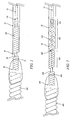
- Fig. 1 schematically depicts one embodiment of the invention.
- the distal end of pusher (or core, the terms are used interchangeably herein) wire 10 is coupled to the proximal end of helical coil 100 by weld junction 110.
- Helical coil 100 may be open or closed pitch and the pitch itself can be varied to establish a desired degree of softness or pliability in region of the device.
- Pusher wire 10 is encased in non-conducting substance 20.
- Weld junction 110 and helical coil 100 are also encased in non-conductive substance 20.
- Non-conducting substance 20 can be any suitable insulating material such as poly(tetrafluoroethylene) (Teflon ® ), poly(paraxylene) (Parylene ® ), poly(ethylene terephthalate) (PET), poly(cyanoacrylates) and the like.
- Pusher wire 10 may be made of any material that has sufficient resilience/flexibility to permit accurate movement and placement of its distal end at a target site in a patient's body by manipulation of the wire at its proximal end, which may be many centimeters away. While this includes material such as carbon fiber and polymers, it is presently preferred that pusher wire 10 be stainless steel or nitinol.
- Helical coil 100 likewise can be made of any conductive substance with the appropriate mechanical characteristics. It is presently preferred that helical coil 100 be of the same material as pusher wire 10.
- Non-conductive bushing 50 may optionally be included at the distal end of insulating layer 20 to provide additional isolation of electrolytic detachment site 30 from helical coil 100.
- Detachment site 30 is coupled to embolic assembly 120 by another conductive substance that has a different standard electrode potential (E 0 ) than that of detachment site 30.
- E 0 standard electrode potential
- the conductive substance is shown as a wire helically-wound around detachment site 30. This, however, is not to be construed as the only way to connect embolic assembly 120 and the delivery device. Any manner of connection such as wire winding, spot welds, pressure clips, etc. that permit close contact of the first conductive substance of detachment site 30 and the second conductive substance will suffice.
- helical coil 70 is wound around the distal end of electrolytic detachment site 30 and partially encased in a mass of non-conductive substance 80.
- Non-conductive substance 80 can be any insulating substance, fusable polymers being particularly useful.
- the proximal end of embolic assembly 120 is also encased in non-conductive substance 80.
- connector 70 is a conducting metal that has a different E 0 than the metal of which detachment site 30 is comprised. While any two metals that have the required E 0 difference may be used, it is presently preferred that separation locus 30 be stainless steel or nitinol and connector 70 be a platinum/tungsten alloy.
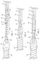
- Pusher wire 10 is coupled to helically-wound segment 410 of wire 400. Segment 420 of wire 400 is open-pitched helically wound. Pusher wire 10, segment 410 and segment 420 of wire 400 are encased in non-conductive substance 20. As in the above embodiments, a non-conductive bushing 50 may be attached to the distal end of non-conductive substance 20 to further isolate open-pitched segment 420 of wire 4.00 from closed-pitched segment 430 of wire 4.00. Segment 430 is optionally coated with a non-conductive substance, which may be the same substance used to encase pusher wire 10 and segment 420 or it may be a different non-conducting substance.
- the term "encased” refers to the complete surrounding of an element of this invention such that the individual features of the element are not readily apparent from the outside of the encasing substance.
- the helically-wound nature of a wire encased in a substance would not be apparent to the casual observer.
- surface-coated it means that the element so-coated retained its appearance; i.e., a surface coated helically-wound wire appears to the casual observer as a helically wound wire.
- a typical example of "surface-coated” would be a common insulated electrical wire available for purchase at a hardware store.
- the distal end of segment 430 is bare and comprises detachment site 440.
- the proximal end of helical coil 450 is tightly wrapped around the distal portion of separation locus 440 to bind the two together.
- helical coil 450 and separation locus 440 are made of metals or alloys having different values of E o . While coil 450 and locus 440 can be made of any metals or alloys that exhibit the required difference in E o , it is presently preferred that detachment site 440 be stainless steel or nitinol and helical coil 450 be a platinum/titanium alloy.
- the distal end of coil 450 is embedded in a fusible, non-conductive polymeric mass 470.
- embolic assembly 480 is also embedded in polymeric mass 470.
- Optional stretch-resistant member 460 may be attached at one end to the distal end of pusher wire 10 and at the other end to detachment site 440 and threaded through the lumen described by the coiled segments of wire 400. Member 460 provides stretch resistance to wire 400 in the helical regions. Member 460 may be made of any resilient, non-stretchable material. In general, polymeric materials having the requisite characteristics are most often used.
- Fig. 2 represents a version of this embodiment of the invention. That is, while segment 420 is shown as open-pitched and segment 430 as closed-pitched, it is entirely possible, and it is within the scope of this invention, that this be reversed, i.e., that segment 420 be closed-pitched and segment 430 be open-pitched. Likewise, both segments can be closed-pitched or open pitched, this latter configuration being shown schematically in Fig. 3 . Furthermore, while Fig. 2 shows the point of separation of segments 420 and 430 as coincidently being the distal end of non-conductive substance 20 or, optionally, the distal end of non-conductive bushing 50, such is not necessarily the case.
- non-conductive substance 20 may be anywhere along the length of segment 420 or segment 430.
- segment 430 and detachment site 440 are shown being coupled to embolic assembly 480 by helically-wound wire 450 and non-conductive substance 470. There are, however, many ways that this connection can be made give and such will become apparent to those skilled in the art based on the disclosures herein. All such configuration are within the scope of this invention.
- Figure 4 depicts a device that is not in accordance with this invention in which increased flexibility is introduced into the device by means of interlinking loops 60 and 95.
- pusher wire 10 is encased in non-conductive substance 20, with enough of wire 10 being left exposed at its proximal end to attach to a power supply.
- a portion of its distal end is also left bare to provide detachment site 30.
- Non-conductive substance can be any of those discussed above with regard to the other embodiments of this invention.
- a non-conductive bushing 50 may optionally be included to provide additional separation of the encased portion of pusher wire 10 from detachment site 30.
- Electrolytic separation of embolic member 120 is accomplished by virtue of connecting entity 70, which comprises a metal having a different E o than that of pusher wire 10.
- connecting entity 70 which comprises a metal having a different E o than that of pusher wire 10.
- the metal with the lower E 0 will erode away resulting in release of embolic member 120.
- embolic member 120 is attached to pusher wire 10 by a mass of non-conducting substance 80, which may be the same as, or different than, the non-conducting substance that is used to encase pusher wire 10. While any combination of metals for core wire 10 and connector 70 that have the requisite difference in E o may be used, typically core wire 1.0 is stainless steel or nitinol and connector 70 is a platinum/zirconium alloy.
- Eyelet loop 60 can be made of any non-conductive material. Presently preferred are those that can form a fiber or fiber-like structure, such as PET. Embolic assembly member 40 has a distal helically wound coil region 90 and an eyelet loop 95, which is interlinked with eyelet loop 60. As above, the embodiments shown in Fig. 4 are exemplary only and other configurations are possible without exceeding the scope of this invention. For example, region 90 of embolic assembly 40 need not necessarily be a helically-wound wire but may simply be, for example without limitation, a straight segment of wire or even a flat piece of metal.
- Fig. 5 is a schematic representation of yet another embodiment of this invention, which combines the elements of the devices above.
- the distal end of pusher wire 10 is coupled to the proximal end of helical coil 100 by weld junction 110.
- Helical coil 100 may be open or closed pitch, and the pitch itself may be varied, to establish a desired degree of softness or pliability.
- Pusher wire 10, weld junction 110 and helical coil 100 are encased in non-conductive substance 20.
- Non-conductive substance 20 can be any of the materials mentioned above with regard to the first and second described embodiments of this invention or any other material that meets the requirements of the disclosures herein.
- non-conductive bushing 50 may optionally be included at the distal end of insulating layer 20 to provide additional isolation of eyelet loop 300, whereat electrolytic separation of embolic assembly 120 will occur.
- Coil 70 and eyelet loop 310 are made of an electrically-conductive substance, preferably a metal or alloy that has a different E o from the substance, also preferably a metal, of which eyelet loop 300 is made. While any combination of metals or alloys that has the required difference in E o may be used, it is presently preferred that eyelet loop 300 be stainless steel and that eyelet loop 310 be a platinum/titanium alloy.
- Helical coil 70 is embedded in a mass of non-conductive substance 80. Also embedded in substance 80 is the proximal end of embolic assembly 120.
- Substance 80 can be any non-conductive material that can be melted or fused to encase the distal end of coil 70 and the proximal end of assembly 120.
- a polymeric material, such as PET, is presently preferred.
Landscapes
- Health & Medical Sciences (AREA)
- Surgery (AREA)
- Life Sciences & Earth Sciences (AREA)
- Heart & Thoracic Surgery (AREA)
- Molecular Biology (AREA)
- Vascular Medicine (AREA)
- Engineering & Computer Science (AREA)
- Biomedical Technology (AREA)
- Reproductive Health (AREA)
- Medical Informatics (AREA)
- Nuclear Medicine, Radiotherapy & Molecular Imaging (AREA)
- Animal Behavior & Ethology (AREA)
- General Health & Medical Sciences (AREA)
- Public Health (AREA)
- Veterinary Medicine (AREA)
- Neurosurgery (AREA)
- Surgical Instruments (AREA)
Applications Claiming Priority (2)
| Application Number | Priority Date | Filing Date | Title |
|---|---|---|---|
| US10/407,295 US7651513B2 (en) | 2003-04-03 | 2003-04-03 | Flexible embolic device delivery system |
| PCT/US2004/009364 WO2004091713A2 (en) | 2003-04-03 | 2004-03-25 | Flexible embolic device delivery system |
Publications (2)
| Publication Number | Publication Date |
|---|---|
| EP1615592A2 EP1615592A2 (en) | 2006-01-18 |
| EP1615592B1 true EP1615592B1 (en) | 2009-06-24 |
Family
ID=33097511
Family Applications (1)
| Application Number | Title | Priority Date | Filing Date |
|---|---|---|---|
| EP04759001A Expired - Lifetime EP1615592B1 (en) | 2003-04-03 | 2004-03-25 | Flexible embolic device delivery system |
Country Status (8)
| Country | Link |
|---|---|
| US (2) | US7651513B2 (https=) |
| EP (1) | EP1615592B1 (https=) |
| JP (1) | JP4617301B2 (https=) |
| AT (1) | ATE434419T1 (https=) |
| CA (1) | CA2520754C (https=) |
| DE (1) | DE602004021684D1 (https=) |
| ES (1) | ES2328038T3 (https=) |
| WO (1) | WO2004091713A2 (https=) |
Families Citing this family (57)
| Publication number | Priority date | Publication date | Assignee | Title |
|---|---|---|---|---|
| DE102004003265A1 (de) | 2004-01-21 | 2005-08-11 | Dendron Gmbh | Vorrichtung zur Implantation von elektrisch isolierten Okklusionswendeln |
| US7608089B2 (en) * | 2004-12-22 | 2009-10-27 | Boston Scientific Scimed, Inc. | Vaso-occlusive device having pivotable coupling |
| EP1884208B1 (en) * | 2005-05-24 | 2015-02-25 | Kaneka Corporation | Medical wire |
| US20060271097A1 (en) * | 2005-05-31 | 2006-11-30 | Kamal Ramzipoor | Electrolytically detachable implantable devices |
| US9636115B2 (en) * | 2005-06-14 | 2017-05-02 | Stryker Corporation | Vaso-occlusive delivery device with kink resistant, flexible distal end |
| GB0512319D0 (en) * | 2005-06-16 | 2005-07-27 | Angiomed Ag | Catheter device variable pusher |
| US20070135826A1 (en) | 2005-12-01 | 2007-06-14 | Steve Zaver | Method and apparatus for delivering an implant without bias to a left atrial appendage |
| US7344558B2 (en) * | 2006-02-28 | 2008-03-18 | Cordis Development Corporation | Embolic device delivery system |
| US8366720B2 (en) * | 2006-07-31 | 2013-02-05 | Codman & Shurtleff, Inc. | Interventional medical device system having an elongation retarding portion and method of using the same |
| US8926650B2 (en) * | 2006-11-20 | 2015-01-06 | Boston Scientific Scimed, Inc. | Mechanically detachable vaso-occlusive device |
| US20080319522A1 (en) * | 2007-06-22 | 2008-12-25 | Von Lehe Cathleen | Aneurysm filler detacher |
| US20080319523A1 (en) * | 2007-06-22 | 2008-12-25 | Neuro Vasx, Inc | Aneurysm filler device |
| US9907555B2 (en) * | 2007-08-09 | 2018-03-06 | Boston Scientific Scimed, Inc. | Guided detachable interlock and method of use |
| US20090275971A1 (en) * | 2007-10-30 | 2009-11-05 | Boston Scientific Scimed, Inc. | Energy activated preloaded detachment mechanisms for implantable devices |
| WO2009073398A1 (en) * | 2007-12-03 | 2009-06-11 | Boston Scientific Scimed, Inc. | Implantable device with electrolytically detachable junction having multiple fine wires |
| AU2008345596B2 (en) * | 2007-12-21 | 2013-09-05 | Microvention, Inc. | A system and method of detecting implant detachment |
| JP5366974B2 (ja) * | 2007-12-21 | 2013-12-11 | マイクロベンション インコーポレイテッド | 分離可能なインプラントの分離域の位置を決定するシステムおよび方法 |
| WO2010028300A1 (en) | 2008-09-04 | 2010-03-11 | Curaseal Inc. | Inflatable device for enteric fistula treatment |
| WO2010038634A1 (ja) * | 2008-09-30 | 2010-04-08 | テルモ株式会社 | ステントデリバリーシステム |
| JP5483377B2 (ja) * | 2008-10-13 | 2014-05-07 | ストライカー コーポレイション | 血管閉鎖コイル供給システム |
| US8657870B2 (en) * | 2009-06-26 | 2014-02-25 | Biosensors International Group, Ltd. | Implant delivery apparatus and methods with electrolytic release |
| US8357179B2 (en) * | 2009-07-08 | 2013-01-22 | Concentric Medical, Inc. | Vascular and bodily duct treatment devices and methods |
| US20110009941A1 (en) * | 2009-07-08 | 2011-01-13 | Concentric Medical, Inc. | Vascular and bodily duct treatment devices and methods |
| US8529596B2 (en) | 2009-07-08 | 2013-09-10 | Concentric Medical, Inc. | Vascular and bodily duct treatment devices and methods |
| US8795317B2 (en) * | 2009-07-08 | 2014-08-05 | Concentric Medical, Inc. | Embolic obstruction retrieval devices and methods |
| US8357178B2 (en) * | 2009-07-08 | 2013-01-22 | Concentric Medical, Inc. | Vascular and bodily duct treatment devices and methods |
| US8795345B2 (en) * | 2009-07-08 | 2014-08-05 | Concentric Medical, Inc. | Vascular and bodily duct treatment devices and methods |
| US9474532B2 (en) * | 2009-09-09 | 2016-10-25 | Kaneka Corporation | Embolization coil |
| KR20130054952A (ko) * | 2010-04-14 | 2013-05-27 | 마이크로벤션, 인코포레이티드 | 임플란트 전달 장치 |
| US9220506B2 (en) | 2010-06-16 | 2015-12-29 | DePuy Synthes Products, Inc. | Occlusive device with stretch resistant member and anchor filament |
| US9931232B2 (en) * | 2010-10-21 | 2018-04-03 | Boston Scientific Scimed, Inc. | Stent delivery system |
| AU2012211992C1 (en) | 2011-02-04 | 2016-07-21 | Concentric Medical, Inc. | Vascular and bodily duct treatment devices and methods |
| US20120203322A1 (en) * | 2011-02-07 | 2012-08-09 | Eells Robert M | Quick release mechanism for medical device deployment |
| EP2484310A1 (de) * | 2011-02-08 | 2012-08-08 | Biotronik AG | Herzklappenprothese mit flexiblen Befestigungen und Implantationsvorrichtung dafür |
| JP6122424B2 (ja) | 2011-06-16 | 2017-04-26 | キュラシール インコーポレイテッド | 瘻孔処置用デバイス及びその関連方法 |
| JP6127042B2 (ja) | 2011-06-17 | 2017-05-10 | キュラシール インコーポレイテッド | 瘻孔処置用デバイスと方法 |
| US20130066359A1 (en) * | 2011-09-13 | 2013-03-14 | Stryker Nv Operations Limited | Vaso-occlusive device |
| EP2668914A1 (en) * | 2012-06-01 | 2013-12-04 | Acandis GmbH & Co. KG | Implant system |
| US9326774B2 (en) | 2012-08-03 | 2016-05-03 | Covidien Lp | Device for implantation of medical devices |
| US9101473B2 (en) * | 2013-03-07 | 2015-08-11 | Medtronic Vascular, Inc. | Venous valve repair prosthesis for treatment of chronic venous insufficiency |
| US20160022271A1 (en) * | 2013-03-11 | 2016-01-28 | DeLois Marlene Ferry | Flat wound detachable embolization coil |
| US9149278B2 (en) * | 2013-03-13 | 2015-10-06 | DePuy Synthes Products, Inc. | Occlusive device delivery system with mechanical detachment |
| US9629739B2 (en) | 2013-03-13 | 2017-04-25 | DePuy Synthes Products, LLC | Distal capture device for a self-expanding stent |
| US9808599B2 (en) | 2013-12-20 | 2017-11-07 | Microvention, Inc. | Device delivery system |
| US9808256B2 (en) | 2014-08-08 | 2017-11-07 | Covidien Lp | Electrolytic detachment elements for implant delivery systems |
| US9814466B2 (en) | 2014-08-08 | 2017-11-14 | Covidien Lp | Electrolytic and mechanical detachment for implant delivery systems |
| US9855050B2 (en) | 2014-09-19 | 2018-01-02 | DePuy Synthes Products, Inc. | Vasculature occlusion device detachment system with tapered corewire and single loop fuse detachment |
| US9782178B2 (en) | 2014-09-19 | 2017-10-10 | DePuy Synthes Products, Inc. | Vasculature occlusion device detachment system with tapered corewire and heater activated fiber detachment |
| EP3212100B1 (en) | 2014-10-31 | 2022-06-29 | Medtronic Advanced Energy LLC | Power monitoring circuitry and system for reducing leakage current in rf generators |
| US9717503B2 (en) | 2015-05-11 | 2017-08-01 | Covidien Lp | Electrolytic detachment for implant delivery systems |
| US10639456B2 (en) | 2015-09-28 | 2020-05-05 | Microvention, Inc. | Guidewire with torque transmission element |
| US10828039B2 (en) | 2016-06-27 | 2020-11-10 | Covidien Lp | Electrolytic detachment for implantable devices |
| US10828037B2 (en) | 2016-06-27 | 2020-11-10 | Covidien Lp | Electrolytic detachment with fluid electrical connection |
| US11051822B2 (en) | 2016-06-28 | 2021-07-06 | Covidien Lp | Implant detachment with thermal activation |
| US12114863B2 (en) | 2018-12-05 | 2024-10-15 | Microvention, Inc. | Implant delivery system |
| CN112656476B (zh) * | 2020-12-31 | 2025-12-30 | 神遁医疗科技(上海)有限公司 | 一种栓塞物及其制备方法 |
| CN117297694A (zh) * | 2023-11-01 | 2023-12-29 | 苏州铨通医疗科技有限公司 | 植入物解脱装置及植入物解脱方法 |
Family Cites Families (46)
| Publication number | Priority date | Publication date | Assignee | Title |
|---|---|---|---|---|
| US5106407A (en) * | 1984-05-04 | 1992-04-21 | The Dow Chemical Company | Iodones and methods for antimicrobial use |
| US4867173A (en) * | 1986-06-30 | 1989-09-19 | Meadox Surgimed A/S | Steerable guidewire |
| US4994069A (en) * | 1988-11-02 | 1991-02-19 | Target Therapeutics | Vaso-occlusion coil and method |
| US5122136A (en) * | 1990-03-13 | 1992-06-16 | The Regents Of The University Of California | Endovascular electrolytically detachable guidewire tip for the electroformation of thrombus in arteries, veins, aneurysms, vascular malformations and arteriovenous fistulas |
| US5354295A (en) * | 1990-03-13 | 1994-10-11 | Target Therapeutics, Inc. | In an endovascular electrolytically detachable wire and tip for the formation of thrombus in arteries, veins, aneurysms, vascular malformations and arteriovenous fistulas |
| US6083220A (en) * | 1990-03-13 | 2000-07-04 | The Regents Of The University Of California | Endovascular electrolytically detachable wire and tip for the formation of thrombus in arteries, veins, aneurysms, vascular malformations and arteriovenous fistulas |
| US6425893B1 (en) * | 1990-03-13 | 2002-07-30 | The Regents Of The University Of California | Method and apparatus for fast electrolytic detachment of an implant |
| US5108407A (en) | 1990-06-08 | 1992-04-28 | Rush-Presbyterian St. Luke's Medical Center | Method and apparatus for placement of an embolic coil |
| US5217484A (en) * | 1991-06-07 | 1993-06-08 | Marks Michael P | Retractable-wire catheter device and method |
| US5261916A (en) * | 1991-12-12 | 1993-11-16 | Target Therapeutics | Detachable pusher-vasoocclusive coil assembly with interlocking ball and keyway coupling |
| DK0791333T3 (da) * | 1991-12-12 | 2000-05-01 | Target Therapeutics Inc | Adskillelig udstøder-karokklusionsspiralkonstruktion med sammenlåsende kobling |
| US5234437A (en) * | 1991-12-12 | 1993-08-10 | Target Therapeutics, Inc. | Detachable pusher-vasoocclusion coil assembly with threaded coupling |
| US5527338A (en) * | 1992-09-02 | 1996-06-18 | Board Of Regents, The University Of Texas System | Intravascular device |
| US5350397A (en) * | 1992-11-13 | 1994-09-27 | Target Therapeutics, Inc. | Axially detachable embolic coil assembly |
| US5250071A (en) * | 1992-09-22 | 1993-10-05 | Target Therapeutics, Inc. | Detachable embolic coil assembly using interlocking clasps and method of use |
| US5423829A (en) * | 1993-11-03 | 1995-06-13 | Target Therapeutics, Inc. | Electrolytically severable joint for endovascular embolic devices |
| US5624449A (en) * | 1993-11-03 | 1997-04-29 | Target Therapeutics | Electrolytically severable joint for endovascular embolic devices |
| US5795331A (en) * | 1994-01-24 | 1998-08-18 | Micro Therapeutics, Inc. | Balloon catheter for occluding aneurysms of branch vessels |
| WO1995023558A1 (en) * | 1994-03-03 | 1995-09-08 | Target Therapeutics, Inc. | Method for detecting separation of a vasoocclusion device |
| US5690671A (en) * | 1994-12-13 | 1997-11-25 | Micro Interventional Systems, Inc. | Embolic elements and methods and apparatus for their delivery |
| IL116561A0 (en) * | 1994-12-30 | 1996-03-31 | Target Therapeutics Inc | Severable joint for detachable devices placed within the body |
| US6059779A (en) * | 1995-04-28 | 2000-05-09 | Target Therapeutics, Inc. | Delivery catheter for electrolytically detachable implant |
| US5853418A (en) * | 1995-06-30 | 1998-12-29 | Target Therapeutics, Inc. | Stretch resistant vaso-occlusive coils (II) |
| US5667767A (en) | 1995-07-27 | 1997-09-16 | Micro Therapeutics, Inc. | Compositions for use in embolizing blood vessels |
| GB9515986D0 (en) * | 1995-08-04 | 1995-10-04 | Racal Health & Safety Ltd | Uni-directional fluid valve |
| US5702361A (en) * | 1996-01-31 | 1997-12-30 | Micro Therapeutics, Inc. | Method for embolizing blood vessels |
| EP0928195B1 (en) * | 1996-05-31 | 2003-01-02 | Micro Therapeutics, Inc. | Compositions for use in embolizing blood vessels |
| US5980514A (en) * | 1996-07-26 | 1999-11-09 | Target Therapeutics, Inc. | Aneurysm closure device assembly |
| US5695480A (en) * | 1996-07-29 | 1997-12-09 | Micro Therapeutics, Inc. | Embolizing compositions |
| US5830178A (en) * | 1996-10-11 | 1998-11-03 | Micro Therapeutics, Inc. | Methods for embolizing vascular sites with an emboilizing composition comprising dimethylsulfoxide |
| US5964797A (en) * | 1996-08-30 | 1999-10-12 | Target Therapeutics, Inc. | Electrolytically deployable braided vaso-occlusion device |
| WO1999008607A1 (en) * | 1997-08-05 | 1999-02-25 | Boston Scientific Limited | Detachable aneurysm neck bridge |
| US6063070A (en) * | 1997-08-05 | 2000-05-16 | Target Therapeutics, Inc. | Detachable aneurysm neck bridge (II) |
| US6086577A (en) * | 1997-08-13 | 2000-07-11 | Scimed Life Systems, Inc. | Detachable aneurysm neck bridge (III) |
| US5916235A (en) * | 1997-08-13 | 1999-06-29 | The Regents Of The University Of California | Apparatus and method for the use of detachable coils in vascular aneurysms and body cavities |
| US6156061A (en) * | 1997-08-29 | 2000-12-05 | Target Therapeutics, Inc. | Fast-detaching electrically insulated implant |
| US5984929A (en) * | 1997-08-29 | 1999-11-16 | Target Therapeutics, Inc. | Fast detaching electronically isolated implant |
| US6146373A (en) * | 1997-10-17 | 2000-11-14 | Micro Therapeutics, Inc. | Catheter system and method for injection of a liquid embolic composition and a solidification agent |
| US5941888A (en) * | 1998-02-18 | 1999-08-24 | Target Therapeutics, Inc. | Vaso-occlusive member assembly with multiple detaching points |
| US6077260A (en) * | 1998-02-19 | 2000-06-20 | Target Therapeutics, Inc. | Assembly containing an electrolytically severable joint for endovascular embolic devices |
| EP0951870A1 (fr) * | 1998-04-21 | 1999-10-27 | Medicorp S.A. | Dispositif pour le traitement d'anévrisme |
| US5935148A (en) * | 1998-06-24 | 1999-08-10 | Target Therapeutics, Inc. | Detachable, varying flexibility, aneurysm neck bridge |
| US6303100B1 (en) * | 1999-03-19 | 2001-10-16 | Micro Therapeutics, Inc. | Methods for inhibiting the formation of potential endoleaks associated with endovascular repair of abdominal aortic aneurysms |
| DE10010840A1 (de) * | 1999-10-30 | 2001-09-20 | Dendron Gmbh | Vorrichtung zur Implantation von Occlusionswendeln |
| US6397850B1 (en) * | 2000-02-09 | 2002-06-04 | Scimed Life Systems Inc | Dual-mode apparatus and method for detection of embolic device detachment |
| DE10118017B4 (de) * | 2001-04-10 | 2017-04-13 | Dendron Gmbh | Occlusionswendel und Vorrichtung zur Implantation von Occlusionswendeln |
-
2003
- 2003-04-03 US US10/407,295 patent/US7651513B2/en active Active
-
2004
- 2004-03-25 WO PCT/US2004/009364 patent/WO2004091713A2/en not_active Ceased
- 2004-03-25 JP JP2006509363A patent/JP4617301B2/ja not_active Expired - Lifetime
- 2004-03-25 ES ES04759001T patent/ES2328038T3/es not_active Expired - Lifetime
- 2004-03-25 CA CA2520754A patent/CA2520754C/en not_active Expired - Fee Related
- 2004-03-25 EP EP04759001A patent/EP1615592B1/en not_active Expired - Lifetime
- 2004-03-25 AT AT04759001T patent/ATE434419T1/de not_active IP Right Cessation
- 2004-03-25 DE DE602004021684T patent/DE602004021684D1/de not_active Expired - Lifetime
-
2010
- 2010-01-05 US US12/652,565 patent/US20100106162A1/en not_active Abandoned
Also Published As
| Publication number | Publication date |
|---|---|
| CA2520754C (en) | 2011-11-15 |
| JP4617301B2 (ja) | 2011-01-26 |
| US20100106162A1 (en) | 2010-04-29 |
| US20040199175A1 (en) | 2004-10-07 |
| US7651513B2 (en) | 2010-01-26 |
| WO2004091713A3 (en) | 2004-12-02 |
| CA2520754A1 (en) | 2004-10-28 |
| ATE434419T1 (de) | 2009-07-15 |
| ES2328038T3 (es) | 2009-11-06 |
| DE602004021684D1 (https=) | 2009-08-06 |
| WO2004091713A2 (en) | 2004-10-28 |
| JP2006521880A (ja) | 2006-09-28 |
| EP1615592A2 (en) | 2006-01-18 |
Similar Documents
| Publication | Publication Date | Title |
|---|---|---|
| EP1615592B1 (en) | Flexible embolic device delivery system | |
| US5759161A (en) | Medical wire and method for leaving implanted devices | |
| EP2444010B1 (en) | Medical implant detachment systems | |
| JP5677955B2 (ja) | 複合脱離機構 | |
| JP4106178B2 (ja) | 迅速取り外し電気絶縁インプラント | |
| EP0715502B1 (en) | Electrolytically severable coil assembly with movable detachment point | |
| US5846210A (en) | Medical wire having implanted device and method for using the same | |
| US6425893B1 (en) | Method and apparatus for fast electrolytic detachment of an implant | |
| JP2610412B2 (ja) | 血管内塞栓用具のための電気分解的分離可能な接合部 | |
| CA2166142C (en) | Solderless electrolytically severable joint for detachable devices placed within the mammalian body | |
| US5891058A (en) | Coiled embolizing material | |
| EP2227163B1 (en) | Implantable device with electrolytically detachable junction having multiple fine wires | |
| US20060271097A1 (en) | Electrolytically detachable implantable devices | |
| JP2002503509A (ja) | 複数の脱着点を有する血管閉塞部材アセンブリ | |
| EP1333763A2 (en) | Implantable devices with polymeric detachment junction | |
| EP2668914A1 (en) | Implant system | |
| AU6349499A (en) | Vascular occlusion device with adjustable length | |
| US20220361888A1 (en) | Embolic Coil And Detachment System |
Legal Events
| Date | Code | Title | Description |
|---|---|---|---|
| PUAI | Public reference made under article 153(3) epc to a published international application that has entered the european phase |
Free format text: ORIGINAL CODE: 0009012 |
|
| 17P | Request for examination filed |
Effective date: 20051102 |
|
| AK | Designated contracting states |
Kind code of ref document: A2 Designated state(s): AT BE BG CH CY CZ DE DK EE ES FI FR GB GR HU IE IT LI LU MC NL PL PT RO SE SI SK TR |
|
| AX | Request for extension of the european patent |
Extension state: AL LT LV MK |
|
| RIN1 | Information on inventor provided before grant (corrected) |
Inventor name: TEOH, CLIFFORD Inventor name: PIZARRO, MARIA Inventor name: PORTER, STEPHEN, C. Inventor name: JAEGER, KEVIN Inventor name: WALLACE, MICHAEL, P. |
|
| RIN1 | Information on inventor provided before grant (corrected) |
Inventor name: PIZARRO, MARIA Inventor name: TEOH, CLIFFORD Inventor name: PORTER, STEPHEN, C. Inventor name: WALLACE, MICHAEL, P. Inventor name: JAEGER, KEVIN |
|
| DAX | Request for extension of the european patent (deleted) | ||
| RIN1 | Information on inventor provided before grant (corrected) |
Inventor name: JAEGER, KEVIN Inventor name: TEOH, CLIFFORD Inventor name: PORTER, STEPHEN, C. Inventor name: PIZARRO, MARIA Inventor name: WALLACE, MICHAEL, P. |
|
| 17Q | First examination report despatched |
Effective date: 20071113 |
|
| GRAP | Despatch of communication of intention to grant a patent |
Free format text: ORIGINAL CODE: EPIDOSNIGR1 |
|
| GRAS | Grant fee paid |
Free format text: ORIGINAL CODE: EPIDOSNIGR3 |
|
| GRAA | (expected) grant |
Free format text: ORIGINAL CODE: 0009210 |
|
| AK | Designated contracting states |
Kind code of ref document: B1 Designated state(s): AT BE BG CH CY CZ DE DK EE ES FI FR GB GR HU IE IT LI LU MC NL PL PT RO SE SI SK TR |
|
| REG | Reference to a national code |
Ref country code: GB Ref legal event code: FG4D |
|
| REG | Reference to a national code |
Ref country code: CH Ref legal event code: EP |
|
| REG | Reference to a national code |
Ref country code: IE Ref legal event code: FG4D |
|
| REF | Corresponds to: |
Ref document number: 602004021684 Country of ref document: DE Date of ref document: 20090806 Kind code of ref document: P |
|
| PG25 | Lapsed in a contracting state [announced via postgrant information from national office to epo] |
Ref country code: AT Free format text: LAPSE BECAUSE OF FAILURE TO SUBMIT A TRANSLATION OF THE DESCRIPTION OR TO PAY THE FEE WITHIN THE PRESCRIBED TIME-LIMIT Effective date: 20090624 Ref country code: FI Free format text: LAPSE BECAUSE OF FAILURE TO SUBMIT A TRANSLATION OF THE DESCRIPTION OR TO PAY THE FEE WITHIN THE PRESCRIBED TIME-LIMIT Effective date: 20090624 |
|
| REG | Reference to a national code |
Ref country code: ES Ref legal event code: FG2A Ref document number: 2328038 Country of ref document: ES Kind code of ref document: T3 |
|
| PG25 | Lapsed in a contracting state [announced via postgrant information from national office to epo] |
Ref country code: PL Free format text: LAPSE BECAUSE OF FAILURE TO SUBMIT A TRANSLATION OF THE DESCRIPTION OR TO PAY THE FEE WITHIN THE PRESCRIBED TIME-LIMIT Effective date: 20090624 Ref country code: SI Free format text: LAPSE BECAUSE OF FAILURE TO SUBMIT A TRANSLATION OF THE DESCRIPTION OR TO PAY THE FEE WITHIN THE PRESCRIBED TIME-LIMIT Effective date: 20090624 Ref country code: SE Free format text: LAPSE BECAUSE OF FAILURE TO SUBMIT A TRANSLATION OF THE DESCRIPTION OR TO PAY THE FEE WITHIN THE PRESCRIBED TIME-LIMIT Effective date: 20090924 |
|
| NLV1 | Nl: lapsed or annulled due to failure to fulfill the requirements of art. 29p and 29m of the patents act | ||
| PG25 | Lapsed in a contracting state [announced via postgrant information from national office to epo] |
Ref country code: EE Free format text: LAPSE BECAUSE OF FAILURE TO SUBMIT A TRANSLATION OF THE DESCRIPTION OR TO PAY THE FEE WITHIN THE PRESCRIBED TIME-LIMIT Effective date: 20090624 Ref country code: CZ Free format text: LAPSE BECAUSE OF FAILURE TO SUBMIT A TRANSLATION OF THE DESCRIPTION OR TO PAY THE FEE WITHIN THE PRESCRIBED TIME-LIMIT Effective date: 20090624 |
|
| PG25 | Lapsed in a contracting state [announced via postgrant information from national office to epo] |
Ref country code: SK Free format text: LAPSE BECAUSE OF FAILURE TO SUBMIT A TRANSLATION OF THE DESCRIPTION OR TO PAY THE FEE WITHIN THE PRESCRIBED TIME-LIMIT Effective date: 20090624 Ref country code: NL Free format text: LAPSE BECAUSE OF FAILURE TO SUBMIT A TRANSLATION OF THE DESCRIPTION OR TO PAY THE FEE WITHIN THE PRESCRIBED TIME-LIMIT Effective date: 20090624 Ref country code: BE Free format text: LAPSE BECAUSE OF FAILURE TO SUBMIT A TRANSLATION OF THE DESCRIPTION OR TO PAY THE FEE WITHIN THE PRESCRIBED TIME-LIMIT Effective date: 20090624 |
|
| PG25 | Lapsed in a contracting state [announced via postgrant information from national office to epo] |
Ref country code: PT Free format text: LAPSE BECAUSE OF FAILURE TO SUBMIT A TRANSLATION OF THE DESCRIPTION OR TO PAY THE FEE WITHIN THE PRESCRIBED TIME-LIMIT Effective date: 20091024 Ref country code: BG Free format text: LAPSE BECAUSE OF FAILURE TO SUBMIT A TRANSLATION OF THE DESCRIPTION OR TO PAY THE FEE WITHIN THE PRESCRIBED TIME-LIMIT Effective date: 20090924 |
|
| PG25 | Lapsed in a contracting state [announced via postgrant information from national office to epo] |
Ref country code: DK Free format text: LAPSE BECAUSE OF FAILURE TO SUBMIT A TRANSLATION OF THE DESCRIPTION OR TO PAY THE FEE WITHIN THE PRESCRIBED TIME-LIMIT Effective date: 20090624 |
|
| PLBE | No opposition filed within time limit |
Free format text: ORIGINAL CODE: 0009261 |
|
| STAA | Information on the status of an ep patent application or granted ep patent |
Free format text: STATUS: NO OPPOSITION FILED WITHIN TIME LIMIT |
|
| 26N | No opposition filed |
Effective date: 20100325 |
|
| PG25 | Lapsed in a contracting state [announced via postgrant information from national office to epo] |
Ref country code: GR Free format text: LAPSE BECAUSE OF FAILURE TO SUBMIT A TRANSLATION OF THE DESCRIPTION OR TO PAY THE FEE WITHIN THE PRESCRIBED TIME-LIMIT Effective date: 20090925 Ref country code: MC Free format text: LAPSE BECAUSE OF NON-PAYMENT OF DUE FEES Effective date: 20100331 |
|
| REG | Reference to a national code |
Ref country code: CH Ref legal event code: PL |
|
| PG25 | Lapsed in a contracting state [announced via postgrant information from national office to epo] |
Ref country code: LI Free format text: LAPSE BECAUSE OF NON-PAYMENT OF DUE FEES Effective date: 20100331 Ref country code: CH Free format text: LAPSE BECAUSE OF NON-PAYMENT OF DUE FEES Effective date: 20100331 |
|
| PG25 | Lapsed in a contracting state [announced via postgrant information from national office to epo] |
Ref country code: CY Free format text: LAPSE BECAUSE OF FAILURE TO SUBMIT A TRANSLATION OF THE DESCRIPTION OR TO PAY THE FEE WITHIN THE PRESCRIBED TIME-LIMIT Effective date: 20090624 |
|
| PG25 | Lapsed in a contracting state [announced via postgrant information from national office to epo] |
Ref country code: LU Free format text: LAPSE BECAUSE OF NON-PAYMENT OF DUE FEES Effective date: 20100325 Ref country code: HU Free format text: LAPSE BECAUSE OF FAILURE TO SUBMIT A TRANSLATION OF THE DESCRIPTION OR TO PAY THE FEE WITHIN THE PRESCRIBED TIME-LIMIT Effective date: 20091225 |
|
| PG25 | Lapsed in a contracting state [announced via postgrant information from national office to epo] |
Ref country code: TR Free format text: LAPSE BECAUSE OF FAILURE TO SUBMIT A TRANSLATION OF THE DESCRIPTION OR TO PAY THE FEE WITHIN THE PRESCRIBED TIME-LIMIT Effective date: 20090624 |
|
| REG | Reference to a national code |
Ref country code: GB Ref legal event code: 732E Free format text: REGISTERED BETWEEN 20121011 AND 20121017 |
|
| REG | Reference to a national code |
Ref country code: ES Ref legal event code: PC2A Owner name: STRYKER N.V. OPERATIONS LIMITED Effective date: 20121105 |
|
| REG | Reference to a national code |
Ref country code: DE Ref legal event code: R081 Ref document number: 602004021684 Country of ref document: DE Owner name: STRYKER NV OPERATIONS LTD., IE Free format text: FORMER OWNER: BOSTON SCIENTIFIC LTD., ST. MICHAEL, BB Effective date: 20121129 Ref country code: DE Ref legal event code: R081 Ref document number: 602004021684 Country of ref document: DE Owner name: STRYKER CORP., US Free format text: FORMER OWNER: BOSTON SCIENTIFIC LTD., ST. MICHAEL, BB Effective date: 20121129 Ref country code: DE Ref legal event code: R082 Ref document number: 602004021684 Country of ref document: DE Representative=s name: BARDEHLE PAGENBERG PARTNERSCHAFT PATENTANWAELT, DE Effective date: 20121129 Ref country code: DE Ref legal event code: R082 Ref document number: 602004021684 Country of ref document: DE Representative=s name: BARDEHLE PAGENBERG PARTNERSCHAFT MBB PATENTANW, DE Effective date: 20121129 Ref country code: DE Ref legal event code: R081 Ref document number: 602004021684 Country of ref document: DE Owner name: STRYKER NV OPERATIONS LTD., IE Free format text: FORMER OWNER: BOSTON SCIENTIFIC LTD., ST. MICHAEL, BARBADOS, BB Effective date: 20121129 Ref country code: DE Ref legal event code: R081 Ref document number: 602004021684 Country of ref document: DE Owner name: STRYKER CORP., KALAMAZOO, US Free format text: FORMER OWNER: BOSTON SCIENTIFIC LTD., ST. MICHAEL, BARBADOS, BB Effective date: 20121129 Ref country code: DE Ref legal event code: R081 Ref document number: 602004021684 Country of ref document: DE Owner name: STRYKER EUROPEAN HOLDINGS I, LLC (N.D. GES. D., US Free format text: FORMER OWNER: BOSTON SCIENTIFIC LTD., ST. MICHAEL, BARBADOS, BB Effective date: 20121129 |
|
| REG | Reference to a national code |
Ref country code: FR Ref legal event code: TP Owner name: STRYKER CORPORATION, US Effective date: 20130103 |
|
| PGFP | Annual fee paid to national office [announced via postgrant information from national office to epo] |
Ref country code: FR Payment date: 20140311 Year of fee payment: 11 Ref country code: IT Payment date: 20140314 Year of fee payment: 11 Ref country code: ES Payment date: 20140211 Year of fee payment: 11 |
|
| PGFP | Annual fee paid to national office [announced via postgrant information from national office to epo] |
Ref country code: GB Payment date: 20140319 Year of fee payment: 11 |
|
| PG25 | Lapsed in a contracting state [announced via postgrant information from national office to epo] |
Ref country code: RO Free format text: LAPSE BECAUSE OF FAILURE TO SUBMIT A TRANSLATION OF THE DESCRIPTION OR TO PAY THE FEE WITHIN THE PRESCRIBED TIME-LIMIT Effective date: 20090624 |
|
| GBPC | Gb: european patent ceased through non-payment of renewal fee |
Effective date: 20150325 |
|
| PG25 | Lapsed in a contracting state [announced via postgrant information from national office to epo] |
Ref country code: IT Free format text: LAPSE BECAUSE OF NON-PAYMENT OF DUE FEES Effective date: 20150325 |
|
| REG | Reference to a national code |
Ref country code: FR Ref legal event code: ST Effective date: 20151130 |
|
| PG25 | Lapsed in a contracting state [announced via postgrant information from national office to epo] |
Ref country code: GB Free format text: LAPSE BECAUSE OF NON-PAYMENT OF DUE FEES Effective date: 20150325 |
|
| PG25 | Lapsed in a contracting state [announced via postgrant information from national office to epo] |
Ref country code: FR Free format text: LAPSE BECAUSE OF NON-PAYMENT OF DUE FEES Effective date: 20150331 |
|
| REG | Reference to a national code |
Ref country code: DE Ref legal event code: R082 Ref document number: 602004021684 Country of ref document: DE Representative=s name: BARDEHLE PAGENBERG PARTNERSCHAFT MBB PATENTANW, DE Ref country code: DE Ref legal event code: R081 Ref document number: 602004021684 Country of ref document: DE Owner name: STRYKER EUROPEAN HOLDINGS I, LLC (N.D. GES. D., US Free format text: FORMER OWNERS: STRYKER CORP., KALAMAZOO, MICH., US; STRYKER MEDTECH LIMITED, VALLETTA, MT Ref country code: DE Ref legal event code: R081 Ref document number: 602004021684 Country of ref document: DE Owner name: STRYKER EUROPEAN HOLDINGS I, LLC (N.D. GES. D., US Free format text: FORMER OWNERS: STRYKER CORP., KALAMAZOO, MICH., US; STRYKER NV OPERATIONS LTD., DUBLIN, IE Ref country code: DE Ref legal event code: R081 Ref document number: 602004021684 Country of ref document: DE Owner name: STRYKER CORP., KALAMAZOO, US Free format text: FORMER OWNERS: STRYKER CORP., KALAMAZOO, MICH., US; STRYKER MEDTECH LIMITED, VALLETTA, MT Ref country code: DE Ref legal event code: R081 Ref document number: 602004021684 Country of ref document: DE Owner name: STRYKER CORP., KALAMAZOO, US Free format text: FORMER OWNERS: STRYKER CORP., KALAMAZOO, MICH., US; STRYKER NV OPERATIONS LTD., DUBLIN, IE |
|
| REG | Reference to a national code |
Ref country code: ES Ref legal event code: FD2A Effective date: 20160805 |
|
| PG25 | Lapsed in a contracting state [announced via postgrant information from national office to epo] |
Ref country code: ES Free format text: LAPSE BECAUSE OF NON-PAYMENT OF DUE FEES Effective date: 20150326 |
|
| PGFP | Annual fee paid to national office [announced via postgrant information from national office to epo] |
Ref country code: IE Payment date: 20230110 Year of fee payment: 20 |
|
| PGFP | Annual fee paid to national office [announced via postgrant information from national office to epo] |
Ref country code: DE Payment date: 20230131 Year of fee payment: 20 |
|
| P01 | Opt-out of the competence of the unified patent court (upc) registered |
Effective date: 20230523 |
|
| REG | Reference to a national code |
Ref country code: DE Ref legal event code: R071 Ref document number: 602004021684 Country of ref document: DE |
|
| REG | Reference to a national code |
Ref country code: IE Ref legal event code: MK9A |
|
| PG25 | Lapsed in a contracting state [announced via postgrant information from national office to epo] |
Ref country code: IE Free format text: LAPSE BECAUSE OF EXPIRATION OF PROTECTION Effective date: 20240325 |
|
| PG25 | Lapsed in a contracting state [announced via postgrant information from national office to epo] |
Ref country code: IE Free format text: LAPSE BECAUSE OF EXPIRATION OF PROTECTION Effective date: 20240325 |