EP1615252A1 - Bewegliche Kontakteinheit für eine Kontaktanordnung eines Schutzschalters - Google Patents
Bewegliche Kontakteinheit für eine Kontaktanordnung eines Schutzschalters Download PDFInfo
- Publication number
- EP1615252A1 EP1615252A1 EP04405415A EP04405415A EP1615252A1 EP 1615252 A1 EP1615252 A1 EP 1615252A1 EP 04405415 A EP04405415 A EP 04405415A EP 04405415 A EP04405415 A EP 04405415A EP 1615252 A1 EP1615252 A1 EP 1615252A1
- Authority
- EP
- European Patent Office
- Prior art keywords
- contact
- unit according
- carrier
- pivot axis
- contact unit
- Prior art date
- Legal status (The legal status is an assumption and is not a legal conclusion. Google has not performed a legal analysis and makes no representation as to the accuracy of the status listed.)
- Granted
Links
- 238000005452 bending Methods 0.000 claims abstract description 17
- 230000008878 coupling Effects 0.000 claims description 5
- 238000010168 coupling process Methods 0.000 claims description 5
- 238000005859 coupling reaction Methods 0.000 claims description 5
- 239000011810 insulating material Substances 0.000 claims description 3
- 238000010791 quenching Methods 0.000 description 8
- 230000000171 quenching effect Effects 0.000 description 8
- 230000005540 biological transmission Effects 0.000 description 5
- 238000009826 distribution Methods 0.000 description 2
- 238000010276 construction Methods 0.000 description 1
- 238000007599 discharging Methods 0.000 description 1
- 230000003628 erosive effect Effects 0.000 description 1
- 238000010304 firing Methods 0.000 description 1
- 238000012423 maintenance Methods 0.000 description 1
- 230000014759 maintenance of location Effects 0.000 description 1
- 238000004519 manufacturing process Methods 0.000 description 1
- 239000000463 material Substances 0.000 description 1
- 238000000465 moulding Methods 0.000 description 1
- 238000005192 partition Methods 0.000 description 1
- 238000009527 percussion Methods 0.000 description 1
- 238000003860 storage Methods 0.000 description 1
Images

Classifications
-
- H—ELECTRICITY
- H01—ELECTRIC ELEMENTS
- H01H—ELECTRIC SWITCHES; RELAYS; SELECTORS; EMERGENCY PROTECTIVE DEVICES
- H01H71/00—Details of the protective switches or relays covered by groups H01H73/00 - H01H83/00
- H01H71/10—Operating or release mechanisms
- H01H71/50—Manual reset mechanisms which may be also used for manual release
- H01H71/52—Manual reset mechanisms which may be also used for manual release actuated by lever
- H01H71/526—Manual reset mechanisms which may be also used for manual release actuated by lever the lever forming a toggle linkage with a second lever, the free end of which is directly and releasably engageable with a contact structure
-
- H—ELECTRICITY
- H01—ELECTRIC ELEMENTS
- H01H—ELECTRIC SWITCHES; RELAYS; SELECTORS; EMERGENCY PROTECTIVE DEVICES
- H01H1/00—Contacts
- H01H1/12—Contacts characterised by the manner in which co-operating contacts engage
- H01H1/14—Contacts characterised by the manner in which co-operating contacts engage by abutting
- H01H1/22—Contacts characterised by the manner in which co-operating contacts engage by abutting with rigid pivoted member carrying the moving contact
- H01H1/221—Contacts characterised by the manner in which co-operating contacts engage by abutting with rigid pivoted member carrying the moving contact and a contact pressure spring acting between the pivoted member and a supporting member
- H01H2001/223—Contacts characterised by the manner in which co-operating contacts engage by abutting with rigid pivoted member carrying the moving contact and a contact pressure spring acting between the pivoted member and a supporting member using a torsion spring
Definitions
- circuit breakers designed as circuit-breakers are used for the rapid and reliable protection of low-voltage lines, motors, equipment and systems against the consequences of overload and short-circuit currents. They each usually have a thermal release with a bimetal and an electromagnetic release with a coil and a percussion anchor and cooperating with a quenching contact arrangement, which generally has one or two switching points.
- the contact assembly includes one or two fixed contact pieces and a cooperating movable contact unit with a contact piece or with two integrated into a contact bridge generally contact pieces.
- a movable contact unit of the aforementioned type is described in EP 0 616 350 A1.
- the contact unit described is part of a contact arrangement of a circuit breaker and includes an elongated contact carrier, one end of which is pivotally mounted on a fixed axis held in the housing of the circuit breaker, and the other end formed as a contact and in the on state of the circuit breaker on a fixed contact piece of the contact arrangement is supported.
- the contact carrier holds a lever pivotally mounted on the fixed axis and a two-armed lever whose pivot point is arranged approximately in the center of the contact carrier.
- An impact surface arm of the two-armed lever cooperates with a firing pin of a thermally and magnetically acting trigger, whereas the other arm carries a latch hook.
- the Verklinkungshaken and the latch lever form a generally referred to as a switch lock Verklinkungsstelle the circuit breaker.
- the switch lock is closed when you turn on the circuit breaker by tilting a frictionally coupled via a transmission bracket with the ratchet lever lever is tilted while charging a spring accumulator in a preferred position.
- the release triggers and opens the switch lock via the release pin.
- the movable contact unit is rotated about the fixed axis and opened the contact arrangement of the circuit breaker.
- the object is to provide a movable contact unit of the type mentioned, a contact arrangement with such a movable contact unit and a circuit breaker with this contact arrangement, which with a simple design and low maintenance requirements enable a high breaking capacity.
- the movable contact unit in addition to a contact carrier and a release lever is arranged on a pivot axis, and is placed on the contact carrier a contact piece and held with at least one mounted on the pivot axis, prestressed bending spring.
- a rapid assembly or disassembly of the movable contact unit according to the invention and a simple metering of the contact force is made possible by a spiral spring, which has a penetrated by the pivot axis cylindrical coil spring with two mutually rotatable legs, of which legs one on the contact carrier and the other under education the bias is supported on the contact piece.
- a spiral spring can easily be attached to the pivot axis and fixed by bending both lever arms in a simple manner and under fixation of contact carrier, contact piece, pivot axis and release lever.
- the two helical springs are frictionally coupled to one another by the U-shaped connecting section, so that the spring is fixed axially.
- a groove on the contact carrier for holding one of the legs of the spiral spring can therefore be omitted.
- the contact carrier is made of insulating material and holds instead of a contact piece a two contact pieces bearing contact bridge.
- a particularly good retention of the contact bridge is achieved if the base of the U designed as a plate has an opening into which a nose formed in the contact carrier protrudes. Through this opening also formed in the release lever arm can be performed, which is actuated by a trigger element of a preferably thermally or magnetically acting release unit.
- FIG. 1 shows a part of a circuit breaker after removal of a housing surrounding the switch.
- This part of the circuit breaker includes a contact arrangement 1 with two series-connected switching points and two each one of the two switching points associated with arc quenching. Of the two switching points, only one can be seen in FIG. This also applies to the two arc extinguishing devices, of which the recognizable is denoted by the reference numeral 2.
- the recognizable switching point is formed by a movable contact piece 111 and a fixed contact piece 30 of the contact arrangement 1.
- the arc quenching device 2 includes two arc runners 21, 22 and an extinguishing plate containing arc quenching chamber 23.
- the not apparent second switching point and the unillustrated second arc quenching device are similarly formed and arranged substantially mirror-symmetrical to a plane lying in the plane of the dividing wall 24.
- the movable contact piece 111 is part of a movable contact unit 10, which is pivotable about an axis 12 mounted in the switch housing. The further construction of the movable contact unit 10 will be explained below with reference to FIGS 2 to 5.
- the contact piece 111 is part of a contact bridge 11, which is designed in the manner of a U.
- the two legs of the U are formed by the movable contact piece 111 and the corresponding contact piece 112 of Figure 1 not apparent second switching point.
- the base of the U is designed as a plate 113 and has a quadrangular opening 114.
- the plate 113 rests on a flat surface 131 of a contact carrier 13 made of insulating material.
- a projection 132 is formed, on which the plate 113 abuts with its side facing away from the two movable contact pieces 111, 112 side.
- In the opening 114 of the contact bridge 11 projects into the contact carrier 13 molded nose 133.
- the contact carrier 13 carries at its support surface 131 opposite upper end arranged around an axis 134th pivotable pawl lever 135 to which a cooperating with a shift lever system not shown transfer bracket 4 is articulated.
- the contact carrier 13 has two support arms 136 and 137 (FIG. 5) which are guided in parallel and are arranged at a distance from one another in the direction of the pivot axis 12. In not designated openings of these support arms, the pivot axis 134 of the pawl 135 ( Figure 3) and also the pivot axis 12 ( Figure 5) are mounted. From Figure 5 it can be seen that in the space between the two support arms 136, 137 a pivot point of the two-armed executed release lever 14 holding nose 142 is arranged. In this nose a groove 143 is inserted, which serves to receive a torque-generating and the trigger lever 14 in the clockwise direction resetting spring 144.
- the release lever 14 carries two plug-in parts 146, 147 ( Figure 3) of two connecting elements to adjacent poles of the circuit breaker and an unrecognizable stop for an executed as a hook end of the pawl 135.
- a left-pointing finger 145 of the trigger lever 14 and pointing to the right Fingers 141 (FIGS. 2 and 4), which are guided through the opening 114 (FIG. 3) and an unspecified opening of the contact carrier 13, can be actuated by two differently arranged thermally activatable triggers of the circuit breaker.
- the trigger 14 can be acted upon by a magnetically activated trigger the circuit breaker with force. For this purpose, it has an impact surface 148 (FIG. 4).
- the movable contact piece 111 is pressed with such a strong bias against the fixed contact piece 30 (and correspondingly the not visible movable contact piece 112 against another fixed contact piece), that abutting the projection 132 contact bridge 11 in the counterclockwise direction around the projection 132nd is pivoted and lifted from the support surface 131.
- suitable dimensioning of the bending springs 51, 52 not only the desired contact force, but at the same time Griffinnachfederung can be achieved. Burning of the contact pieces and the associated loss of material can be compensated while maintaining a sufficiently sized contact force by tracking the movable contact pieces 111 and 112 and the contact bridge 11 by means of the bending springs 51, 52.
- the spiral springs 51 and 52 each have a penetrated by the pivot axis 12 cylindrical coil spring 511 and 521 each having two mutually rotated legs 512, 513 and 521, 523.
- the legs 513 and 523 are each held in a molded-in contact carrier 13 groove 138 and 139, whereas in the legs 512 and 522 holding fingers 515 and 525 are formed, which respectively to form the bias voltage.
- the contact force (in the ON state of the circuit breaker) on the contact bridge 11 and the two movable contact pieces 110 and 112 are supported.
- a magnetic or thermal trigger of the circuit breaker is activated and a trigger member of one of the triggers will then strike either finger 141 or 145 or the impact surface 148.
- the release lever 14 is now rotated in the counterclockwise direction against the force of the return spring 144 and this repealed a release of the release lever 14 and the pawl 135 formed.
- the standing under the action of a non-illustrated loaded spring storage movable contact unit 10 is pivoted counterclockwise and the Contact arrangement 1 opened to form two series-connected switching arcs.
- the circuit breaker After deleting the switching arcs in the arc quenching device 2, the circuit breaker can be turned on again. In this case, 4 force is transmitted to the pawl 135 and the hinged thereto, latched contact unit 10 of a shift lever system, not shown on the apparent from Fig. 2 transmission bracket. By charging the spring accumulator and forming the predetermined contact force, the movable contact unit is guided clockwise into the switch-on according to FIG.
- a simplification of the described embodiment of the movable contact unit 10 is achieved if only one bending spring is used instead of two bending springs.
- This bending spring may be one of the two spiral springs 51 or 52.
- the movable contact unit then has only one movable contact piece 111 or 112.
- a spiral spring is provided with two penetrated by the pivot axis, cylindrical coil springs and a two coiled springs frictionally coupling and supported on the contact carrier U-shaped connecting portion and two legs, which in each case connect one of the two coil springs and forming the bias on the contact bridge 11, respectively. support the contact pieces 111, 112.
- Such a spring designated by the reference numeral 53 is shown in phantom in FIG.
- this spring contains the two springs 51 and 52, but additionally has a connecting portion shown in dashed lines, which complements with the two legs 512 and 522 to the U-shaped connecting portion 531.
- the spring 53 may be formed from the two springs 51 and 52 also by connecting the two fingers 515 and 525 with a dotted center portion. The spring 53 then has a the two coil springs 511 and 521 frictionally coupling and supported on the contact bridge 11 U-shaped connecting portion 532. The two legs 513 and 523 are then supported in the grooves 138 and 139 of the Kunststoffanni13.
Landscapes
- Breakers (AREA)
- Arc-Extinguishing Devices That Are Switches (AREA)
Abstract
Description
- Die vorliegende Erfindung bezieht sich auf das Gebiet der Schutzschalter für Niederspannungsverteilnetze. Sie betrifft eine bewegliche Kontakteinheit für eine Kontaktanordnung eines Schutzschalters nach dem Oberbegriff von Patentanspruch 1 sowie eine Kontaktanordnung mit einer solchen Kontakteinheit und einen Schutzschalter mit dieser Kontaktanordnung.
- In Niederspannungsverteilnetzen dienen als Installationseinbauschalter ausgeführte Schutzschalter dem raschen und zuverlässigen Schutz von unter Niederspannung stehenden Leitungen, Motoren, Apparaten und Anlagen vor den Folgen von Überlast und Kurzschlussströmen. Sie weisen jeweils zumeist einen thermischen Auslöser mit einem Bimetall und einen elektromagnetischen Auslöser mit einer Spule und einem Schlaganker auf und eine mit einer Löscheinrichtung zusammenwirkende Kontaktanordnung, welche im allgemeinen eine oder zwei Schaltstellen aufweist. Je nach Ausbildung mit einer oder zwei Schaltstellen enthält die Kontaktanordnung ein oder zwei feststehende Kontaktstücke sowie eine damit zusammenarbeitende bewegliche Kontakteinheit mit einem Kontaktstück oder mit zwei im allgemeinen in eine Kontaktbrücke integrierten Kontaktstücken.
- Eine bewegliche Kontakteinheit der vorgenannten Art ist in EP 0 616 350 A1 beschrieben. Die beschriebene Kontakteinheit ist Teil einer Kontaktanordnung eines Schutzschalters und enthält einen gestreckt ausgebildeten Kontaktträger, dessen eines Ende an einer im Gehäuse des Schutzschalters gehaltenen feststehenden Achse schwenkbar gelagert ist, und dessen anderes Ende als Kontaktstück ausgebildet und im Einschaltzustand des Schutzschalters auf einem feststehenden Kontaktstück der Kontaktanordnung abgestützt ist. Der Kontaktträger hält einen an der feststehenden Achse schwenkbar gelagerten Klinkenhebel sowie einen zweiarmigen Hebel, dessen Drehpunkt etwa in der Mitte des Kontaktträgers angeordnet ist. Ein mit einer Aufschlagfläche versehener Arm des zweiarmigen Hebels wirkt mit einem Auslösestift eines thermisch und magnetisch wirkenden Auslöser zusammen, wohingegen der anderer Arm einen Verklinkungshaken trägt. Der Verklinkungshaken und der Klinkenhebel bilden eine im allgemeinen als Schaltschloss bezeichnete Verklinkungsstelle des Schutzschalters. Das Schaltschloss wird beim Einschalten des Schutzschalters geschlossen, indem ein über einen Übertragungsbügel mit dem Klinkenhebel kraftschlüssig gekoppelter Schalthebel unter gleichzeitigem Aufladen eines Federspeichers in eine Vorzugslage gekippt wird. Beim Auftreten eines Kurzschluss- oder Überstroms löst der Auslöser aus und öffnet über den Auslösestift das Schaltschloss. Durch den sich nun entladenden Federspeicher wird die bewegliche Kontakteinheit um die feststehende Achse verdreht und die Kontaktanordnung des Schutzschalters geöffnet.
- Der Erfindung, wie sie in den Patentansprüchen angegeben ist, liegt die Aufgabe zugrunde, eine bewegliche Kontakteinheit der eingangs genannten Art, eine Kontaktanordnung mit einer solchen beweglichen Kontakteinheit und einen Schutzschalter mit dieser Kontaktanordnung zu schaffen, welche bei einfacher Bauweise und geringen Anforderungen an die Wartung eine hohe Ausschaltleistung ermöglichen.
- Bei der beweglichen Kontakteinheit nach der Erfindung ist neben einem Kontaktträger auch ein Auslösehebel auf einer Schwenkachse angeordnet, und ist auf den Kontaktträger ein Kontaktstück aufgelegt und mit mindestens einer auf der Schwenkachse gelagerten, vorgespannten Biegefeder gehalten. Diese Massnahmen ermöglichen eine einfache Montage der Kontakteinheit durch Aufstecken des Kontaktträgers, des Auslösehebels und einer Auslösefeder auf die Schwenkachse und durch nachfolgendes Fixieren dieser Komponenten und des Kontaktstücks durch eine Biegefeder oder gegebenenfalls zwei Biegefedern. Hierbei ist es besonders vorteilhaft, dass die Biegefeder nicht nur die verschiedenen Komponenten des beweglichen Kontaktteils festsetzt, sondern zugleich auch die Kontaktkraft des lediglich auf den Kontaktträger aufgelegten Kontaktstücks definiert. Dadurch, dass das Kontaktstück auf dem Kontaktträger aufliegt, kann dieses leicht ausgewechselt und durch ein gegebenenfalls anders bemessenes Kontaktstück ersetzt werden.
- Eine rasche Montage oder Demontage der beweglichen Kontakteinheit nach der Erfindung und eine einfache Dosierung der Kontaktkraft wird durch eine Biegefeder ermöglicht, welche eine von der Schwenkachse durchdrungene zylindrische Schraubenfeder mit zwei gegeneinander verdrehbaren Schenkeln aufweist, von welchen Schenkeln einer auf dem Kontaktträger und der andere unter Bildung der Vorspannung auf dem Kontaktstück abgestützt ist. Eine solche Biegefeder kann leicht auch die Schwenkachse aufgesteckt und durch Aufbiegen beider Hebelarme in einfacher Weise und unter Fixierung von Kontaktträger, Kontaktstück, Schwenkachse und Auslösehebel festgesetzt werden. Durch Einformen eines das Kontaktstück hintergreifenden Haltefingers in den auf dem beweglichen Kontaktstück abgestützten Schenkel wird das Kontaktstück mit einfachen Mitteln gehalten, wohingegen der zweite Schenkel mit Vorteil in einer in den Kontaktträger eingeformten Nut gehalten ist.
- Eine besonders stabile bewegbare Kontakteinheit wird erreicht, wenn zwei spiegelsymmetrisch auf der Achse angeordnete Biegefedern vorgesehen sind, oder wenn die Biegefeder als Doppeltorsionsfeder ausgebildet ist und folgende Bestandteile aufweist:
- zwei jeweils von der Schwenkachse durchdrungene, zylindrische Schraubenfedern,
- einen die beiden Schraubenfedern kraftschlüssig koppelnden und auf dem Kontaktträger abgestützten U-förmigen Verbindungsabschnitt, und
- zwei Schenkel, welche sich jeweils an je eine beider Schraubenfedern anschliessen und unter Bildung der Vorspannung auf dem Kontaktstück abgestützt sind.
- Bei der Doppeltorsionsfeder werden die beiden Schraubenfedern durch den U-förmigen Verbindungsabschnitt kraftschlüssig miteinander gekoppelt und so die Feder axial fixiert. Eine Nut am Kontaktträger zum Halten eines der Schenkel der Biegefeder kann daher entfallen.
- Aus Gründen einer hohen Stromtragfähigkeit und einer einfachen Fertigung ist der Kontaktträger aus Isoliermaterial gefertigt und hält anstelle eines Kontaktstücks eine zwei Kontaktstücke tragende Kontaktbrücke.
- Eine durch die Kennlinie der Biegefeder definierte und über einen grossen Weg wirkende Kontaktkraft wird gebildet, wenn die Kontaktbrücke wie folgt ausgebildet ist:
- sie weist die Form eines U auf,
- die beiden Kontaktstücke bilden die Schenkel des U,
- die Basis des U ist als Platte ausgebildet, liegt auf einer Fläche des Kontaktträgers auf und liegt an ihrer von den Kontaktstücken abgewandten Seite an einem in den Kontaktträger eingeformten Vorsprung an.
- Beim Schliessen der Kontaktanordnung schlagen dann nämlich die beiden Kontaktstücke der Kontaktbrücke gegen zwei feststehende Kontaktstücke der Kontaktanordnung und werden anschliessend gegen die Wirkung der Biegefeder um eine vom Vorsprung gebildete Achse verschwenkt. Hierbei wird über einen vergleichsweise grossen Weg eine definierte Kontaktkraft erzeugt. Nicht zu vermeidender Kontaktabbrand kann so gut kompensiert werden.
- Eine besonders gute Halterung der Kontaktbrücke wird erreicht, wenn die als Platte ausgeführte Basis des U eine Öffnung aufweist, in die eine in den Kontaktträger eingeformte Nase ragt. Durch diese Öffnung kann auch ein in den Auslösehebel eingeformter Arm geführt sein, welcher von einem Auslöseelement einer vorzugsweise thermisch oder magnetisch wirkenden Auslöseeinheit betätigbar ist.
- Anhand von Zeichnungen wird nachfolgend ein Ausführungsbeispiel der Erfindung näher erläutert. Hierbei zeigt:
- Fig.1
- eine in Richtung einer Schwenkachse geführte Ansicht eines Teils eines Schutzschalters im Einschaltzustand mit einer eine bewegliche Kontakteinheit nach der Erfindung enthaltenden Kontakteinrichtung und mit einer Lichtbogenlöscheinrichtung,
- Fig.2
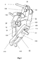
- eine perspektivische Ansicht der Kontakteinheit gemäss Fig.1 im Ausschaltzustand des Schutzschalters, bei der in die Kontakteinheit nun auch ein Klinkenhebel der Kontakteinheit und ein am Klinkenhebel angelenkter Übertragungsbügel zu einem nicht dargestellten Schaltgetriebe eingezeichnet sind,
- Fig.3
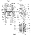
- eine quer zur Schwenkachse geführte Ansicht der Kontakteinheit gemäss Fig.2,
- Fig.4
- eine in Richtung der Schwenkachse geführte Ansicht der Kontakteinheit gemäss Fig.2, und
- Fig.5
- eine Aufsicht in Pfeilrichtung auf einen längs V - V geführten Schnitt durch die Kontakteinheit nach Fig.4.
- In allen Figuren beziehen sich gleiche Bezugszeichen auf gleichwirkende Teile. In Fig.1 ist ein Teil eines Schutzschalters nach Entfernen eines den Schalter umgebenden Gehäuses dargestellt. Dieser Teil des Schutzschalters enthält eine Kontaktanordnung 1 mit zwei in Serie geschalteten Schaltstellen und zwei jeweils einer der beiden Schaltstellen zugeordneten Lichtbogenlöscheinrichtungen. Von den beiden Schaltstellen ist in Fig.1 nur eine zu erkennen. Dies gilt auch für die beiden Lichtbogenlöscheinrichtungen, von denen die erkennbare mit dem Bezugszeichen 2 bezeichnet ist. Die erkennbare Schaltstelle ist von einem beweglichen Kontaktstück 111 und einem feststehenden Kontaktstück 30 der Kontaktanordnung 1 gebildet. Die Lichtbogenlöscheinrichtung 2 enthält zwei Lichtbogenlaufschienen 21, 22 und eine Löschbleche enthaltende Lichtbogenlöschkammer 23. Die nicht ersichtliche zweite Schaltstelle und die nicht ersichtliche zweite Lichtbogenlöscheinrichtung sind ähnlich ausgebildet und im wesentlichen spiegelsymmetrisch zu einer in der Zeichnungsebene liegenden Trennwand 24 angeordnet. Das bewegliche Kontaktstück 111 ist Teil einer beweglichen Kontakteinheit 10, welche um eine im Schaltergehäuse gelagerte Achse 12 schwenkbar ist. Der weitere Aufbau der beweglichen Kontakteinheit 10 wird nachfolgend anhand der Figuren 2 bis 5 erläutert.
- Ersichtlich ist das Kontaktstück 111 Teil einer Kontaktbrücke 11, welche nach Art eines U ausgebildet ist. Die beiden Schenkel des U sind gebildet vom beweglichen Kontaktstück 111 und dem entsprechenden Kontaktstück 112 der aus Fig.1 nicht ersichtlichen zweiten Schaltstelle. Die Basis des U ist als Platte 113 ausgeführt und weist eine viereckige Öffnung 114 auf. Die Platte 113 liegt auf einer ebenen Fläche 131 eines Kontaktträgers 13 aus Isolierstoff auf. In den Kontaktträger 13 ist ein Vorsprung 132 eingeformt, an dem die Platte 113 mit ihrer von den beiden bewegliche Kontaktstücken 111, 112 abgewandten Seite anschlägt. In die Öffnung 114 der Kontaktbrücke 11 ragt eine in den Kontaktträger 13 eingeformte Nase 133. Durch die Öffnung 114 ist ein in einen Auslösehebel 14 eingeformter Finger 141 geführt. Der Kontaktträger 13 trägt an seinem der Auflagefläche131 entgegengesetzt angeordneten oberen Ende einen um eine Achse 134 schwenkbaren Klinkenhebel 135, an den ein mit einem nicht dargestellten Schalthebelsystem zusammenwirkender Übertragungsbügel 4 angelenkt ist.
- Wie aus den Figuren 3 bis 5 ersichtlich ist, weist der Kontaktträger 13 zwei parallel geführte und in Richtung der Schwenkachse 12 voneinander mit Abstand angeordnete Tragarme 136 und 137 (Fig.5) auf. In nicht bezeichneten Öffnungen dieser Tragarme sind die Schwenkachse 134 der Klinke 135 (Fig.3) und auch die Schwenkachse 12 (Fig.5) gelagert. Aus Fig.5 kann entnommen werden, dass im Zwischenraum zwischen den beiden Tragarmen 136, 137 eine den Drehpunkt des zweiarmig ausgeführten Auslösehebels 14 haltende Nase 142 angeordnet ist. In diese Nase ist eine Nut 143 eingelassen, die der Aufnahme einer drehmomenterzeugenden und den Auslösehebel 14 im Uhrzeigersinn rückstellenden Feder 144 dient. Der Auslösehebel 14 trägt zwei Steckteile 146, 147 (Fig.3) zweier Verbindungselemente zu benachbarten Polen des Schutzschalters sowie einen nicht ersichtlichen Anschlag für ein als Haken ausgeführtes Ende der Klinke 135. Ein nach links weisender Finger 145 des Auslösehebels 14 und der nach rechts weisende Finger 141 (Figuren 2 und 4), der durch die Öffnung 114 (Fig.3) sowie eine nicht bezeichnete Öffnung des Kontaktträgers 13 geführt wird, können von zwei unterschiedlich angeordneten thermisch aktivierbaren Auslösern des Schutzschalters betätigt werden. Ebenso kann der Auslöser 14 von einem magnetisch aktivierbaren Auslöser des Schutzschalters mit Kraft beaufschlagt werden. Zu diesem Zweck weist er eine Aufschlagfläche 148 (Fig.4) auf.
- Bei der Montage der beweglichen Kontakteinheit 10 werden der Kontaktträger 14 und der die Rückstellfeder 144 in der Nut 143 haltende Auslösehebel 14 derart zusammengesteckt, dass die Schwenkachse 12 entsprechend Fig.5 durch diese drei Teile geführt werden kann. Nach Auflegen der Kontaktbrücke 11 auf die Auflagefläche 131 des Kontaktträgers 13 werden diese fünf Komponenten mit zwei aus den Figuren 3 und 5 ersichtlichen, auf der Schwenkachse 12 gelagerten Biegefedern 51 und 52 unter Bildung einer mechanisch festen Einheit verspannt. Hierbei werden nicht nur die einzelnen Komponenten, wie Kontaktträger 13, Auslösehebel 14, Schwenkachse 12 und Kontaktbrücke 11 mechanisch fest miteinander verbunden, sondern die Kontaktbrücke 11 und dementsprechend auch die beiden bewegliche Kontaktstücke 111, 112 sind nun im Einschaltzustand des Schalters mit einer durch die Kennlinien der Federn 51 und 52 definierten Kontaktkraft auf den feststehenden Kontaktstücken abgestützt. Dies kann für die von den Kontaktstücken 111 und 30 gebildete Schaltstelle der Fig.1 entnommen werden. Ersichtlich ist im Einschaltzustand das bewegliche Kontaktstück 111 mit einer so starken Vorspannung gegen das feststehende Kontaktstück 30 gedrückt (und entsprechend auch das nicht ersichtliche bewegliche Kontaktstück 112 gegen ein weiteres feststehendes Kontaktstück), dass die am Vorsprung 132 anschlagende Kontaktbrücke 11 im Gegenuhrzeigersinn um den Vorsprung 132 geschwenkt wird und von der Auflagefläche 131 abhebt. Durch geeignete Bemessung der Biegefedern 51, 52 kann nicht nur die erwünschte Kontaktkraft, sondern kann zugleich auch Kontaktnachfederung erreicht werden. Abbrand der Kontaktstücke und damit verbundener Materialverlust kann so unter Beibehalt einer ausreichend bemessenen Kontaktkraft durch Nachführen der beweglichen Kontaktstücke 111 und 112 bzw. der Kontaktbrücke 11 mittels der Biegefedern 51, 52 kompensiert werden.
- Aus Fig.3 ist zu ersehen, dass die Biegefedern 51 bzw. 52 jeweils eine von der Schwenkachse 12 durchdrungene zylindrische Schraubenfeder 511 bzw. 521 aufweisen mit jeweils zwei gegeneinander verdrehten Schenkeln 512, 513 bzw. 521, 523. Die Schenkel 513 und 523 sind jeweils in einer in den Kontaktträger 13 eingeformten Nut 138 bzw. 139 gehalten, wohingegen in die Schenkel 512 und 522 Haltefinger 515 und 525 eingeformt sind, welche unter Bildung der Vorspannung resp. der Kontaktkraft (im Einschaltzustand des Schutzschalters) auf der Kontaktbrücke 11 bzw. den beiden beweglichen Kontaktstücken 110 und 112 abgestützt sind.
- Beim Auftreten eines Kurzschluss- oder Überstroms wird ein magnetisch oder thermisch wirkender Auslöser des Schutzschalters aktiviert und ein Auslöseglied eines der Auslöser schlägt dann an einem beider Finger 141 bzw. 145 oder der Aufschlagfläche 148 an. Der Auslösehebel 14 wird nun im Gegenuhrzeigersinn gegen die Kraft der Rückstellfeder 144 verdreht und hierbei eine vom Auslösehebel 14 und der Klinke 135 gebildete Verklinkung aufgehoben. Die unter der Wirkung eines nicht dargestellten geladenen Federspeichers stehende bewegliche Kontakteinheit 10 wird im Gegenuhrzeigersinn geschwenkt und die Kontaktanordnung 1 unter Bildung zweier in Serie geschalteter Schaltlichtbögen geöffnet.
- Nach Löschen der Schaltlichtbögen in der Lichtbogenlöscheinrichtung 2 kann der Schutzschalter wieder eingeschaltet werden. Hierbei wird von einem nicht dargestellten Schalthebelsystem über den aus Fig. 2 ersichtlichen Übertragungsbügel 4 Kraft auf die Klinke 135 und die daran angelenkte bewegliche, wieder verklinkte Kontakteinheit 10 übertragen. Unter Aufladen des Federspeichers und unter Bildung der vorbestimmten Kontaktkraft wird die bewegliche Kontakteinheit im Uhrzeigersinn in die Einschaltposition gemäss Fig. 1 geführt.
- Eine Vereinfachung der beschriebenen Ausführungsform der beweglichen Kontakteinheit 10 wird erreicht, wenn anstelle zweier Biegefedern lediglich eine Biegefeder verwendet wird. Diese Biegefeder kann eine der beiden Biegefedern 51 oder 52 sein. Mit Vorteil weist die bewegliche Kontakteinheit dann lediglich ein bewegliches Kontaktstück 111 oder 112 auf. Um aber auch Kontaktbrücken 11 gut positionieren zu können, ist eine Biegefeder vorgesehen mit zwei jeweils von der Schwenkachse durchdrungenen, zylindrische Schraubenfedern sowie mit einem die beiden Schraubenfedern kraftschlüssig koppelnden und auf dem Kontaktträger abgestützten U-förmigen Verbindungsabschnitt sowie mit zwei Schenkeln, welche sich jeweils an eine beider Schraubenfedern anschliessen und unter Bildung der Vorspannung auf der Kontaktbrücke 11 resp. den Kontaktstücken 111, 112 abstützen. Eine solche mit dem Bezugszeichen 53 gekennzeichnete Feder ist in Fig.3 teilweise gestrichelt eingezeichnet. Ersichtlich enthält diese Feder die beiden Federn 51 und 52, weist aber zusätzlich noch einen gestrichelt dargestellten Verbindungsabschnitt auf, welcher sich mit den beiden Schenkeln 512 und 522 zum U-förmigen Verbindungsabschnitt 531 ergänzt. Alternativ kann die Feder 53 aus den beiden Federn 51 und 52 auch durch Verbinden der beiden Finger 515 und 525 mit einem punktiert dargestellten Mittelabschnitt erzeugt werden. Die Feder 53 weist dann einen die beiden Schraubenfedern 511 und 521 kraftschlüssig koppelnden und auf der Kontaktbrücke 11 abgestützten U-förmigen Verbindungsabschnitt 532 auf. Die beiden Schenkel 513 und 523 sind dann in den Nuten 138 und 139 des Kontaktträger13 abgestützt.
-
- 1
- Kontaktanordnung
- 10
- bewegliche Kontakteinheit
- 11
- Kontaktbrücke
- 111,112
- bewegliche Kontaktstücke
- 113
- Platte
- 114
- Öffnung
- 12
- Schwenkachse
- 13
- Kontaktträger
- 131
- Auflagefläche
- 132
- Vorsprung
- 133
- Nase
- 134
- Schwenkachse
- 135
- Klinkenhebel, Klinke
- 136, 137
- Tragarme
- 138, 139
- Nuten
- 14
- Auslösehebel
- 141
- Finger
- 142
- Nase
- 143
- Nut
- 144
- Rückstellfeder
- 145
- Finger
- 146, 147
- Steckteile
- 148
- Aufschlagfläche
- 2
- Lichtbogenlöscheinrichtung
- 21,22
- Lichtbogenlaufschienen
- 23
- Lichtbogenlöschkammer
- 24
- Trennwand
- 30
- feststehendes Kontaktstück
- 4
- Übertragungsbügel
- 51,52,53
- Biegefedern
- 511, 521
- Schraubenfedern
- 512, 513, 522, 523
- Schenkel
- 515, 525
- Haltefinger
- 531, 532
- U-förmige Verbindungsabschnitte
Claims (12)
- Bewegliche Kontakteinheit (10) für eine Kontaktanordnung (1) eines Schutzschalters, enthaltend einen Kontaktträger (13) und ein vom Kontaktträger (13) gehaltenes Kontaktstück (111, 112, 11), bei dem der Kontaktträger (13) auf einer im Schalter lagerbaren Schwenkachse (12) angeordnet ist und eine schwenkbare Klinke (135) sowie einen mit der Klinke (135) eine Verklinkungsstelle bildenden, schwenkbaren Auslösehebel (14) trägt, dadurch gekennzeichnet, dass neben dem Kontaktträger (13) auch der Auslösehebel (14) auf der Schwenkachse (12) angeordnet ist, und dass das Kontaktstück (11) auf den Kontaktträger (13) aufgelegt ist und mit mindestens einer auf der Schwenkachse (12) gelagerten, vorgespannten Biegefeder (51, 52, 53) gehalten ist.
- Kontakteinheit nach Anspruch 1, dadurch gekennzeichnet, dass die Biegefeder (51, 52) eine von der Schwenkachse (12) durchdrungene zylindrische Schraubenfeder (511, 521) mit zwei gegeneinander verdrehbaren Schenkeln (512, 513; 522, 523) aufweist, von welchen Schenkeln ein erster (513, 523) auf dem Kontaktträger (13) und der zweite (512, 522) unter Bildung der Vorspannung auf dem Kontaktstück (11) abgestützt ist.
- Kontakteinheit nach Anspruch 2, dadurch gekennzeichnet, dass in den zweiten Schenkel (512, 522) ein das Kontaktstück (11) hintergreifender Haltefinger (515, 525) eingeformt ist.
- Kontakteinheit nach Anspruch 3, dadurch gekennzeichnet, dass der erste Schenkel (512, 522) in einer in den Kontaktträger (13) eingeformten Nut (138, 139) gehalten ist.
- Kontakteinheit nach Anspruch 1, dadurch gekennzeichnet, dass die Biegefeder (53) zwei jeweils von der Schwenkachse (12) durchdrungene, zylindrische Schraubenfedern (511, 521) aufweist sowie einen die beiden Schraubenfedern (511, 521) kraftschlüssig koppelnden und auf dem Kontaktträger (13) abgestützten U-förmigen Verbindungsabschnitt (531) und zwei Schenkel (512, 522), welche sich jeweils an je eine beider Schraubenfedern (511, 521) anschliessen und unter Bildung der Vorspannung auf dem Kontaktstück (11) abgestützt sind.
- Kontakteinheit nach Anspruch 1, dadurch gekennzeichnet, dass die Biegefeder (53) zwei jeweils von der Schwenkachse (12) durchdrungene, zylindrische Schraubenfedern (511, 521) aufweist sowie einen die beiden Schraubenfedern (511, 521) kraftschlüssig koppelnden und auf dem Kontaktstück (11) abgestützten U-förmigen Verbindungsabschnitt (532) und zwei Schenkel (513, 523), welche sich jeweils an je eine beider Schraubenfedern (511, 521) anschliessen und unter Bildung der Vorspannung auf dem Kontaktträger (13) abgestützt sind.
- Kontakteinheit nach einem der Ansprüche 1 bis 6, dadurch gekennzeichnet, dass der Kontaktträger (13) aus Isoliermaterial gefertigt ist und anstelle eines Kontaktstücks eine zwei Kontaktstücke (111, 112) tragende Kontaktbrücke (11) hält.
- Kontakteinheit nach Anspruch 7, dadurch gekennzeichnet, dass die Kontaktbrücke (11) nach Art eines U ausgebildet ist, dass die beiden Kontaktstücke (111, 112) die Schenkel des U bilden, und dass die Basis des U als Platte (113) ausgebildet ist und auf einer Fläche (131) des Kontaktträgers (13) aufliegt und an ihrer von den Kontaktstücken (111, 112) abgewandten Seite an einem in den Kontaktträger (13) eingeformten Vorsprung (132) anschlägt.
- Kontakteinheit nach Anspruch 8, dadurch gekennzeichnet, dass die Platte (113) eine Öffnung (114) aufweist, in die eine in den Kontaktträger (13) eingeformte Nase (132) ragt.
- Kontakteinheit nach Anspruch 9, dadurch gekennzeichnet, dass durch die Öffnung (114) ein in den Auslösehebel (14) eingeformter Finger (141) geführt ist.
- Kontaktanordnung mit der Kontakteinheit nach einem der Ansprüche 1 bis 10.
- Schutzschalter mit der Kontaktanordnung nach Anspruch 11.
Priority Applications (5)
| Application Number | Priority Date | Filing Date | Title |
|---|---|---|---|
| DE502004007985T DE502004007985D1 (de) | 2004-07-05 | 2004-07-05 | Bewegliche Kontakteinheit für eine Kontaktanordnung eines Schutzschalters |
| ES04405415T ES2312946T3 (es) | 2004-07-05 | 2004-07-05 | Unidad de contacto movil para una disposicion de contacto de un interruptor de proteccion. |
| EP04405415A EP1615252B1 (de) | 2004-07-05 | 2004-07-05 | Bewegliche Kontakteinheit für eine Kontaktanordnung eines Schutzschalters |
| AT04405415T ATE407444T1 (de) | 2004-07-05 | 2004-07-05 | Bewegliche kontakteinheit für eine kontaktanordnung eines schutzschalters |
| US11/152,256 US7132912B2 (en) | 2004-07-05 | 2005-06-15 | Moving contact unit for a contact arrangement in a circuit breaker |
Applications Claiming Priority (1)
| Application Number | Priority Date | Filing Date | Title |
|---|---|---|---|
| EP04405415A EP1615252B1 (de) | 2004-07-05 | 2004-07-05 | Bewegliche Kontakteinheit für eine Kontaktanordnung eines Schutzschalters |
Publications (2)
| Publication Number | Publication Date |
|---|---|
| EP1615252A1 true EP1615252A1 (de) | 2006-01-11 |
| EP1615252B1 EP1615252B1 (de) | 2008-09-03 |
Family
ID=34932181
Family Applications (1)
| Application Number | Title | Priority Date | Filing Date |
|---|---|---|---|
| EP04405415A Expired - Lifetime EP1615252B1 (de) | 2004-07-05 | 2004-07-05 | Bewegliche Kontakteinheit für eine Kontaktanordnung eines Schutzschalters |
Country Status (5)
| Country | Link |
|---|---|
| US (1) | US7132912B2 (de) |
| EP (1) | EP1615252B1 (de) |
| AT (1) | ATE407444T1 (de) |
| DE (1) | DE502004007985D1 (de) |
| ES (1) | ES2312946T3 (de) |
Families Citing this family (12)
| Publication number | Priority date | Publication date | Assignee | Title |
|---|---|---|---|---|
| DE102004055564B4 (de) * | 2004-11-18 | 2022-05-05 | Abb Ag | Elektrisches Installationsschaltgerät |
| FR2996678B1 (fr) * | 2012-10-05 | 2014-10-31 | Schneider Electric Ind Sas | Dispositif de commande d'un appareil de protection electrique et appareil de protection electrique le comportant |
| US8809722B2 (en) * | 2012-10-11 | 2014-08-19 | Siemens Industry, Inc. | Circuit breaker with translating electrical contact, circuit breaker electrical contact assemblies, and operational methods |
| CN105914110B (zh) * | 2016-06-20 | 2017-10-20 | 浙江天正电气股份有限公司 | 一种小型断路器 |
| CN108010820B (zh) * | 2017-12-22 | 2024-12-17 | 上海诺雅克电气有限公司 | 断路器 |
| CN108878226B (zh) * | 2018-07-13 | 2024-05-17 | 浙江正泰电器股份有限公司 | 断路器 |
| CN111710539A (zh) * | 2020-07-20 | 2020-09-25 | 上海瑞忒尔电气技术有限公司 | 一种开关装置的触头系统 |
| EP4260355A4 (de) * | 2020-12-14 | 2024-09-04 | ABB S.p.A. | Einstellmechanismus für leistungsschalter und entsprechender leistungsschalter |
| CN114649174A (zh) * | 2020-12-21 | 2022-06-21 | 上海良信电器股份有限公司 | 一种易于安装的动触头系统及其装配方法 |
| CN113161176B (zh) * | 2021-03-25 | 2022-09-13 | 中车株洲电力机车有限公司 | 一种动车用直立式真空断路器传动支架加工方法 |
| CN114220717B (zh) * | 2021-12-21 | 2025-04-11 | 湖北腾明智能电气有限公司 | 一种分合闸机构 |
| CN115424902B (zh) * | 2022-09-07 | 2024-04-23 | 加西亚电子电器股份有限公司 | 一种漏电断路器 |
Citations (6)
| Publication number | Priority date | Publication date | Assignee | Title |
|---|---|---|---|---|
| US2370206A (en) * | 1943-01-19 | 1945-02-27 | Chase Shawmut Co | Circuit breaker |
| US4618745A (en) * | 1985-04-01 | 1986-10-21 | Heinemann Electric Company | Circuit breaker mechanism |
| EP0570647A1 (de) * | 1992-05-13 | 1993-11-24 | Hager Electro S.A. | Schaltschloss für Schutzschalter und Schutzschalter, mit diesem integriert |
| EP0696041A1 (de) * | 1994-08-04 | 1996-02-07 | Legrand | Schutzschalter |
| WO2002052597A1 (en) * | 2000-12-27 | 2002-07-04 | Abb Service Srl | Current limiting circuit breaker |
| US6492607B2 (en) * | 2000-10-19 | 2002-12-10 | Hager Electro | Rapid closure mechanism for electrical contacts |
Family Cites Families (6)
| Publication number | Priority date | Publication date | Assignee | Title |
|---|---|---|---|---|
| US4641001A (en) * | 1984-06-15 | 1987-02-03 | Mitsubishi Denki Kabushiki Kaisha | Circuit interrupter |
| JPH0119315Y2 (de) * | 1984-09-19 | 1989-06-05 | ||
| US5214402A (en) * | 1991-12-23 | 1993-05-25 | North American Philips Corporation | Trip link latch and interpole link for a circuit breaker |
| AT404648B (de) * | 1992-06-29 | 1999-01-25 | Felten & Guilleaume Ag Oester | Selbstschalter |
| CH685524A5 (de) | 1993-03-19 | 1995-07-31 | Maier & Cie C | Leitungsschutzschalter. |
| US5539167A (en) * | 1994-02-14 | 1996-07-23 | Square D. Company | Blade suspension assemlby for a circuit breaker |
-
2004
- 2004-07-05 AT AT04405415T patent/ATE407444T1/de not_active IP Right Cessation
- 2004-07-05 EP EP04405415A patent/EP1615252B1/de not_active Expired - Lifetime
- 2004-07-05 ES ES04405415T patent/ES2312946T3/es not_active Expired - Lifetime
- 2004-07-05 DE DE502004007985T patent/DE502004007985D1/de not_active Expired - Lifetime
-
2005
- 2005-06-15 US US11/152,256 patent/US7132912B2/en not_active Expired - Lifetime
Patent Citations (6)
| Publication number | Priority date | Publication date | Assignee | Title |
|---|---|---|---|---|
| US2370206A (en) * | 1943-01-19 | 1945-02-27 | Chase Shawmut Co | Circuit breaker |
| US4618745A (en) * | 1985-04-01 | 1986-10-21 | Heinemann Electric Company | Circuit breaker mechanism |
| EP0570647A1 (de) * | 1992-05-13 | 1993-11-24 | Hager Electro S.A. | Schaltschloss für Schutzschalter und Schutzschalter, mit diesem integriert |
| EP0696041A1 (de) * | 1994-08-04 | 1996-02-07 | Legrand | Schutzschalter |
| US6492607B2 (en) * | 2000-10-19 | 2002-12-10 | Hager Electro | Rapid closure mechanism for electrical contacts |
| WO2002052597A1 (en) * | 2000-12-27 | 2002-07-04 | Abb Service Srl | Current limiting circuit breaker |
Also Published As
| Publication number | Publication date |
|---|---|
| EP1615252B1 (de) | 2008-09-03 |
| DE502004007985D1 (de) | 2008-10-16 |
| US7132912B2 (en) | 2006-11-07 |
| ES2312946T3 (es) | 2009-03-01 |
| ATE407444T1 (de) | 2008-09-15 |
| US20060001511A1 (en) | 2006-01-05 |
Similar Documents
| Publication | Publication Date | Title |
|---|---|---|
| DE102013211539B4 (de) | Schaltmechanik und elektromechanisches Schutzschaltgerät | |
| EP1615252B1 (de) | Bewegliche Kontakteinheit für eine Kontaktanordnung eines Schutzschalters | |
| DE670790C (de) | Thermisch wirkender Selbstschalter | |
| DE3323474C2 (de) | Stromkreisunterbrecher | |
| DE102013019390B4 (de) | Überspannungsschutzeinrichtung, aufweisend mindestens einen Überspannungsableiter und eine, mit dem Überspannungsableiter in Reihe geschaltete, thermisch auslösbare Schalteinrichtung | |
| DE2504954B2 (de) | Mechanisches sprungwerk, insbesondere fuer kleine hochleistungs-selbstschalter | |
| DE4406670C3 (de) | Leitungsschutzschalter | |
| WO1984001663A1 (fr) | Commutateur electrique de securite d'appareil | |
| EP0621619A1 (de) | Leitungsschutzschalter | |
| DE102004018275B4 (de) | Schaltgerät | |
| DE2118175A1 (de) | Leistungsschalter mit eingebauten Schmelzsicherungen | |
| DE1538466B2 (de) | Ein oder mehrpoliger durckknopfbetaetigter ueberstrom schalter | |
| EP2584582A1 (de) | Baureihe mehrpoliger Leistungsschalter | |
| DE1438953B2 (de) | Selbstschalter | |
| DE1257933B (de) | Elektrischer Leistungsschalter | |
| DE10129498C1 (de) | Mehrpoliges elektrisches Schaltgerät mit Schaltschloss | |
| DE2138381C3 (de) | Schutzschalter, insbesondere Leitungsschutzschalter | |
| DE1588754A1 (de) | Elektrischer Selbstschalter | |
| DE3619240A1 (de) | Leitungsschutzschalter mit einer eine blaseinrichtung bildenden kontaktanordnung | |
| EP0731979B1 (de) | Schutzschalter | |
| DE1638157B1 (de) | Selbstschalter | |
| WO2003009324A1 (de) | Schaltschloss für mehrpolige elektrische schaltgeräte | |
| DE2264342A1 (de) | Ueberstromschutzeinrichtung mit stromabhaengig betaetigbaren schaltstuecken | |
| DE202015100926U1 (de) | Elektrisches Schaltgerät in modularer Bauweise | |
| AT404647B (de) | Elektrischer schutzschalter |
Legal Events
| Date | Code | Title | Description |
|---|---|---|---|
| PUAI | Public reference made under article 153(3) epc to a published international application that has entered the european phase |
Free format text: ORIGINAL CODE: 0009012 |
|
| AK | Designated contracting states |
Kind code of ref document: A1 Designated state(s): AT BE BG CH CY CZ DE DK EE ES FI FR GB GR HU IE IT LI LU MC NL PL PT RO SE SI SK TR |
|
| AX | Request for extension of the european patent |
Extension state: AL HR LT LV MK |
|
| 17P | Request for examination filed |
Effective date: 20060527 |
|
| AKX | Designation fees paid |
Designated state(s): AT BE BG CH CY CZ DE DK EE ES FI FR GB GR HU IE IT LI LU MC NL PL PT RO SE SI SK TR |
|
| 17Q | First examination report despatched |
Effective date: 20070131 |
|
| GRAP | Despatch of communication of intention to grant a patent |
Free format text: ORIGINAL CODE: EPIDOSNIGR1 |
|
| GRAS | Grant fee paid |
Free format text: ORIGINAL CODE: EPIDOSNIGR3 |
|
| GRAA | (expected) grant |
Free format text: ORIGINAL CODE: 0009210 |
|
| AK | Designated contracting states |
Kind code of ref document: B1 Designated state(s): AT BE BG CH CY CZ DE DK EE ES FI FR GB GR HU IE IT LI LU MC NL PL PT RO SE SI SK TR |
|
| REG | Reference to a national code |
Ref country code: GB Ref legal event code: FG4D Free format text: NOT ENGLISH |
|
| REG | Reference to a national code |
Ref country code: CH Ref legal event code: EP |
|
| REG | Reference to a national code |
Ref country code: IE Ref legal event code: FG4D Free format text: LANGUAGE OF EP DOCUMENT: GERMAN |
|
| REF | Corresponds to: |
Ref document number: 502004007985 Country of ref document: DE Date of ref document: 20081016 Kind code of ref document: P |
|
| PG25 | Lapsed in a contracting state [announced via postgrant information from national office to epo] |
Ref country code: NL Free format text: LAPSE BECAUSE OF FAILURE TO SUBMIT A TRANSLATION OF THE DESCRIPTION OR TO PAY THE FEE WITHIN THE PRESCRIBED TIME-LIMIT Effective date: 20080903 |
|
| PG25 | Lapsed in a contracting state [announced via postgrant information from national office to epo] |
Ref country code: SI Free format text: LAPSE BECAUSE OF FAILURE TO SUBMIT A TRANSLATION OF THE DESCRIPTION OR TO PAY THE FEE WITHIN THE PRESCRIBED TIME-LIMIT Effective date: 20080903 Ref country code: FI Free format text: LAPSE BECAUSE OF FAILURE TO SUBMIT A TRANSLATION OF THE DESCRIPTION OR TO PAY THE FEE WITHIN THE PRESCRIBED TIME-LIMIT Effective date: 20080903 |
|
| REG | Reference to a national code |
Ref country code: ES Ref legal event code: FG2A Ref document number: 2312946 Country of ref document: ES Kind code of ref document: T3 |
|
| NLV1 | Nl: lapsed or annulled due to failure to fulfill the requirements of art. 29p and 29m of the patents act | ||
| REG | Reference to a national code |
Ref country code: IE Ref legal event code: FD4D |
|
| PG25 | Lapsed in a contracting state [announced via postgrant information from national office to epo] |
Ref country code: IE Free format text: LAPSE BECAUSE OF FAILURE TO SUBMIT A TRANSLATION OF THE DESCRIPTION OR TO PAY THE FEE WITHIN THE PRESCRIBED TIME-LIMIT Effective date: 20080903 Ref country code: BG Free format text: LAPSE BECAUSE OF FAILURE TO SUBMIT A TRANSLATION OF THE DESCRIPTION OR TO PAY THE FEE WITHIN THE PRESCRIBED TIME-LIMIT Effective date: 20081203 |
|
| PG25 | Lapsed in a contracting state [announced via postgrant information from national office to epo] |
Ref country code: RO Free format text: LAPSE BECAUSE OF FAILURE TO SUBMIT A TRANSLATION OF THE DESCRIPTION OR TO PAY THE FEE WITHIN THE PRESCRIBED TIME-LIMIT Effective date: 20080903 Ref country code: PT Free format text: LAPSE BECAUSE OF FAILURE TO SUBMIT A TRANSLATION OF THE DESCRIPTION OR TO PAY THE FEE WITHIN THE PRESCRIBED TIME-LIMIT Effective date: 20090203 Ref country code: CZ Free format text: LAPSE BECAUSE OF FAILURE TO SUBMIT A TRANSLATION OF THE DESCRIPTION OR TO PAY THE FEE WITHIN THE PRESCRIBED TIME-LIMIT Effective date: 20080903 Ref country code: SK Free format text: LAPSE BECAUSE OF FAILURE TO SUBMIT A TRANSLATION OF THE DESCRIPTION OR TO PAY THE FEE WITHIN THE PRESCRIBED TIME-LIMIT Effective date: 20080903 |
|
| PLBE | No opposition filed within time limit |
Free format text: ORIGINAL CODE: 0009261 |
|
| STAA | Information on the status of an ep patent application or granted ep patent |
Free format text: STATUS: NO OPPOSITION FILED WITHIN TIME LIMIT |
|
| PG25 | Lapsed in a contracting state [announced via postgrant information from national office to epo] |
Ref country code: EE Free format text: LAPSE BECAUSE OF FAILURE TO SUBMIT A TRANSLATION OF THE DESCRIPTION OR TO PAY THE FEE WITHIN THE PRESCRIBED TIME-LIMIT Effective date: 20080903 Ref country code: DK Free format text: LAPSE BECAUSE OF FAILURE TO SUBMIT A TRANSLATION OF THE DESCRIPTION OR TO PAY THE FEE WITHIN THE PRESCRIBED TIME-LIMIT Effective date: 20080903 |
|
| 26N | No opposition filed |
Effective date: 20090604 |
|
| PG25 | Lapsed in a contracting state [announced via postgrant information from national office to epo] |
Ref country code: SE Free format text: LAPSE BECAUSE OF FAILURE TO SUBMIT A TRANSLATION OF THE DESCRIPTION OR TO PAY THE FEE WITHIN THE PRESCRIBED TIME-LIMIT Effective date: 20081203 |
|
| BERE | Be: lapsed |
Owner name: ABB SCHWEIZ A.G. Effective date: 20090731 |
|
| PG25 | Lapsed in a contracting state [announced via postgrant information from national office to epo] |
Ref country code: MC Free format text: LAPSE BECAUSE OF NON-PAYMENT OF DUE FEES Effective date: 20090731 |
|
| REG | Reference to a national code |
Ref country code: CH Ref legal event code: PL |
|
| PG25 | Lapsed in a contracting state [announced via postgrant information from national office to epo] |
Ref country code: CH Free format text: LAPSE BECAUSE OF NON-PAYMENT OF DUE FEES Effective date: 20090731 Ref country code: LI Free format text: LAPSE BECAUSE OF NON-PAYMENT OF DUE FEES Effective date: 20090731 |
|
| PG25 | Lapsed in a contracting state [announced via postgrant information from national office to epo] |
Ref country code: PL Free format text: LAPSE BECAUSE OF FAILURE TO SUBMIT A TRANSLATION OF THE DESCRIPTION OR TO PAY THE FEE WITHIN THE PRESCRIBED TIME-LIMIT Effective date: 20080903 |
|
| PG25 | Lapsed in a contracting state [announced via postgrant information from national office to epo] |
Ref country code: BE Free format text: LAPSE BECAUSE OF NON-PAYMENT OF DUE FEES Effective date: 20090731 |
|
| PG25 | Lapsed in a contracting state [announced via postgrant information from national office to epo] |
Ref country code: GR Free format text: LAPSE BECAUSE OF FAILURE TO SUBMIT A TRANSLATION OF THE DESCRIPTION OR TO PAY THE FEE WITHIN THE PRESCRIBED TIME-LIMIT Effective date: 20081204 |
|
| PG25 | Lapsed in a contracting state [announced via postgrant information from national office to epo] |
Ref country code: AT Free format text: LAPSE BECAUSE OF NON-PAYMENT OF DUE FEES Effective date: 20090705 |
|
| PG25 | Lapsed in a contracting state [announced via postgrant information from national office to epo] |
Ref country code: LU Free format text: LAPSE BECAUSE OF NON-PAYMENT OF DUE FEES Effective date: 20090705 |
|
| PG25 | Lapsed in a contracting state [announced via postgrant information from national office to epo] |
Ref country code: HU Free format text: LAPSE BECAUSE OF FAILURE TO SUBMIT A TRANSLATION OF THE DESCRIPTION OR TO PAY THE FEE WITHIN THE PRESCRIBED TIME-LIMIT Effective date: 20090304 |
|
| PG25 | Lapsed in a contracting state [announced via postgrant information from national office to epo] |
Ref country code: TR Free format text: LAPSE BECAUSE OF FAILURE TO SUBMIT A TRANSLATION OF THE DESCRIPTION OR TO PAY THE FEE WITHIN THE PRESCRIBED TIME-LIMIT Effective date: 20080903 |
|
| PG25 | Lapsed in a contracting state [announced via postgrant information from national office to epo] |
Ref country code: CY Free format text: LAPSE BECAUSE OF FAILURE TO SUBMIT A TRANSLATION OF THE DESCRIPTION OR TO PAY THE FEE WITHIN THE PRESCRIBED TIME-LIMIT Effective date: 20080903 |
|
| PGFP | Annual fee paid to national office [announced via postgrant information from national office to epo] |
Ref country code: ES Payment date: 20150728 Year of fee payment: 12 Ref country code: GB Payment date: 20150721 Year of fee payment: 12 |
|
| REG | Reference to a national code |
Ref country code: FR Ref legal event code: PLFP Year of fee payment: 13 |
|
| GBPC | Gb: european patent ceased through non-payment of renewal fee |
Effective date: 20160705 |
|
| PG25 | Lapsed in a contracting state [announced via postgrant information from national office to epo] |
Ref country code: GB Free format text: LAPSE BECAUSE OF NON-PAYMENT OF DUE FEES Effective date: 20160705 |
|
| REG | Reference to a national code |
Ref country code: FR Ref legal event code: PLFP Year of fee payment: 14 |
|
| PG25 | Lapsed in a contracting state [announced via postgrant information from national office to epo] |
Ref country code: ES Free format text: LAPSE BECAUSE OF NON-PAYMENT OF DUE FEES Effective date: 20160706 |
|
| REG | Reference to a national code |
Ref country code: FR Ref legal event code: PLFP Year of fee payment: 15 |
|
| REG | Reference to a national code |
Ref country code: ES Ref legal event code: FD2A Effective date: 20181203 |
|
| PGFP | Annual fee paid to national office [announced via postgrant information from national office to epo] |
Ref country code: DE Payment date: 20190719 Year of fee payment: 16 Ref country code: IT Payment date: 20190730 Year of fee payment: 16 Ref country code: FR Payment date: 20190719 Year of fee payment: 16 |
|
| REG | Reference to a national code |
Ref country code: DE Ref legal event code: R119 Ref document number: 502004007985 Country of ref document: DE |
|
| PG25 | Lapsed in a contracting state [announced via postgrant information from national office to epo] |
Ref country code: FR Free format text: LAPSE BECAUSE OF NON-PAYMENT OF DUE FEES Effective date: 20200731 |
|
| PG25 | Lapsed in a contracting state [announced via postgrant information from national office to epo] |
Ref country code: DE Free format text: LAPSE BECAUSE OF NON-PAYMENT OF DUE FEES Effective date: 20210202 |
|
| PG25 | Lapsed in a contracting state [announced via postgrant information from national office to epo] |
Ref country code: IT Free format text: LAPSE BECAUSE OF NON-PAYMENT OF DUE FEES Effective date: 20200705 |