EP1610073A2 - Récepteur solaire et procédé de refroidissement d'une fenêtre d'entrée d'un récepteur solaire - Google Patents
Récepteur solaire et procédé de refroidissement d'une fenêtre d'entrée d'un récepteur solaire Download PDFInfo
- Publication number
- EP1610073A2 EP1610073A2 EP05012940A EP05012940A EP1610073A2 EP 1610073 A2 EP1610073 A2 EP 1610073A2 EP 05012940 A EP05012940 A EP 05012940A EP 05012940 A EP05012940 A EP 05012940A EP 1610073 A2 EP1610073 A2 EP 1610073A2
- Authority
- EP
- European Patent Office
- Prior art keywords
- solar radiation
- receiver according
- absorber
- radiation receiver
- cooling fluid
- Prior art date
- Legal status (The legal status is an assumption and is not a legal conclusion. Google has not performed a legal analysis and makes no representation as to the accuracy of the status listed.)
- Withdrawn
Links
Images


Classifications
-
- F—MECHANICAL ENGINEERING; LIGHTING; HEATING; WEAPONS; BLASTING
- F24—HEATING; RANGES; VENTILATING
- F24S—SOLAR HEAT COLLECTORS; SOLAR HEAT SYSTEMS
- F24S70/00—Details of absorbing elements
- F24S70/10—Details of absorbing elements characterised by the absorbing material
-
- F—MECHANICAL ENGINEERING; LIGHTING; HEATING; WEAPONS; BLASTING
- F24—HEATING; RANGES; VENTILATING
- F24S—SOLAR HEAT COLLECTORS; SOLAR HEAT SYSTEMS
- F24S20/00—Solar heat collectors specially adapted for particular uses or environments
- F24S20/20—Solar heat collectors for receiving concentrated solar energy, e.g. receivers for solar power plants
-
- F—MECHANICAL ENGINEERING; LIGHTING; HEATING; WEAPONS; BLASTING
- F24—HEATING; RANGES; VENTILATING
- F24S—SOLAR HEAT COLLECTORS; SOLAR HEAT SYSTEMS
- F24S40/00—Safety or protection arrangements of solar heat collectors; Preventing malfunction of solar heat collectors
- F24S40/50—Preventing overheating or overpressure
- F24S40/55—Arrangements for cooling, e.g. by using external heat dissipating means or internal cooling circuits
-
- Y—GENERAL TAGGING OF NEW TECHNOLOGICAL DEVELOPMENTS; GENERAL TAGGING OF CROSS-SECTIONAL TECHNOLOGIES SPANNING OVER SEVERAL SECTIONS OF THE IPC; TECHNICAL SUBJECTS COVERED BY FORMER USPC CROSS-REFERENCE ART COLLECTIONS [XRACs] AND DIGESTS
- Y02—TECHNOLOGIES OR APPLICATIONS FOR MITIGATION OR ADAPTATION AGAINST CLIMATE CHANGE
- Y02E—REDUCTION OF GREENHOUSE GAS [GHG] EMISSIONS, RELATED TO ENERGY GENERATION, TRANSMISSION OR DISTRIBUTION
- Y02E10/00—Energy generation through renewable energy sources
- Y02E10/40—Solar thermal energy, e.g. solar towers
Definitions
- the invention relates to a solar radiation receiver, comprising a Pressure vessel and an absorber arranged in the pressure vessel for solar radiation, wherein a working medium through the pressure vessel for heat absorption can be guided on the absorber, and arranged on the pressure vessel entrance window for the solar radiation.
- the invention further relates to a method for cooling an entrance window a solar radiation receiver, which can be acted upon by a solar radiation Absorber has.
- Solar radiation receiver serve to solar thermal generated heat to a to pass on gaseous working medium such as air.
- a closed Solar radiation receiver is arranged in a pressure vessel, an absorber, which is heated solar-thermally.
- the radiation passes through the entrance window, which is in particular curved, in the pressure vessel. This entrance window is basically exposed to high heat load.
- Solar radiation receiver are described for example in DE 197 10 986 A1 and DE 100 20 322 A1 describes.
- the invention is based on the object, a solar radiation receiver to provide, in which minimizes the heat load of the entrance window is.
- the entrance window can be at least partially opposite shield this infrared radiation.
- the arranged in the pressure vessel infrared radiation shielding device is opaque to the infrared radiation of the absorber and transparent to the solar radiation. This ensures that solar radiation, which by the Entrance window enters the pressure vessel, the absorber can heat up.
- Permeability to solar radiation is understood to mean that an essential Part of entering through the entrance window solar radiation absorber reached.
- Opak is to be understood that an essential part of the Absorber incoming infrared radiation based on the entrance window intercepted becomes.
- the inventive solution is the heat input to the entrance window greatly reduced from the interior of the pressure vessel ago. Thereby will be the emergence of a high temperature gradient across the wall thickness of the entrance window prevented. This in turn allows mechanical Reduce voltages in the entrance window.
- the inventive solution can be a function separation with respect of the entrance window; the entrance window is pressure-bearing.
- the Infrared radiation shielding means is that part of the solar radiation receiver, which is exposed to the strongest heat load. These Heat load is removed from the entrance window.
- the infrared radiation shielding device serves as absorber or pre-absorber, through which working medium to heat up.
- cooling fluid flow (the cooling fluid Can be working medium) over which the entrance window and the infrared radiation shielding device let cool, with the heated cooling fluid can be used as a working medium.
- the infrared radiation shielding device is arranged and designed so that emanating from the absorber infrared radiation from the entrance window is shielded. This is the heat load of the entrance window due to infrared radiation, which emanates from the absorber, greatly reduced.
- the infrared radiation shielding device is arranged and designed so that emanating from the absorber infrared radiation is intercepted based on the total area of the entrance window. This allows an infra-red radiation exposure of the entrance window over its entire inside, which in an interior of the pressure vessel lies, prevents or at least greatly reduces.
- entrance windows are made of quartz glass. At high Temperatures thereby the problem of devitrification by crystallite formation on.
- the entrance window can be effectively cool, at least in the sense that infrared radiation from the entrance window is shielded. This allows the temperature of the entrance window Keep below a temperature of approx. 800 ° C to 850 ° C. Entglasungsvorêt are relatively slow at these temperatures, d. H. do not find it accelerated instead of.
- the infrared radiation shielding device made of quartz glass is made. Quartz glass is consistent for solar radiation and absorbs infrared radiation. This is just the problem when infrared radiation from the absorber on the entrance window made of quartz glass, as this due to heats the absorbed infrared radiation.
- the infrared radiation shielding device made of quartz glass then absorbs them from the absorber outgoing infrared radiation while sending solar radiation to the absorber passes. The absorbed infrared radiation leading to a heating the infrared radiation shielding device leads, then no longer Entrance window, so that it is less thermally stressed.
- a cooling device for cooling the entrance window is provided on an inner side facing the absorber.
- the cooling device By the cooling device, the temperature of the entrance window can be so keep down that devitrification processes take place at a very low rate.
- the cooling device can also be the infrared radiation shielding device cool.
- a flow is the inside of the entrance window with Cooling fluid provided.
- the cooling fluid used is preferably air.
- the cooling fluid can be branched off from a flow guide for working medium be, with a branch within the pressure vessel or outside the pressure vessel is basically possible.
- Cooling fluid which flows through this gap and thereby the Applied to the inside of the entrance window, leads heat from the entrance window off, d. H. cool this.
- the cooling fluid can also heat from the Infrared radiation shielding are removed and these are cooled.
- the infrared radiation shielding device at least one opening provided by the cooling fluid from the gap can flow to the absorber.
- the cooling fluid may then react with the working fluid mix in the pressure vessel, so that the cooling fluid flow is a partial flow the working medium flow is.
- the cooling fluid is heated in the gap and heated cooling fluid is then supplied to the absorber.
- the infrared radiation shielding device is a pre-absorber since there cooling fluid is preheated as the working medium.
- an opening is in a vertex area the infrared radiation shielding device with respect to the entrance window arranged.
- Heated cooling fluid can reach the absorber via this opening flow to. Cooling fluid can then be in the gap in a foot area couple in and remove from the apex area from the gap. Thereby leaves to achieve a good homogeneous cooling effect; at the coupling in the Foot portion of the gap, the cooling fluid is still cool and points at certain Operating conditions at a lower speed. When the cooling fluid reaches the peak area, then it is heated. By a higher Speed in the apex area (due to reduction in cross section in the gap) is the speed under certain operating conditions there higher, so that over the entire gap area a uniform cooling effect results.
- the opening is aligned coaxially with an axis of the entrance window.
- the infrared radiation shielding device provided with a plurality of openings, so that cooling fluid from the gap over a large area of the infrared radiation shielding device can flow to the absorber.
- this variant leaves there is a uniform flow through the infrared radiation shielding device achieve a uniform cooling effect and a uniform Heating the cooling fluid (which then as a working medium can be used) to achieve.
- the infrared radiation shielding device can be used effectively as a pre-absorber. Furthermore, so can the Prevent the formation of stagnation points.
- a coupling of cooling fluid in the gap in a Foot area of the gap may be provided. This can be at least certain Operating conditions give a homogeneous cooling effect, if in Foot of the gap, the still cool cooling fluid a low speed and in the apex area, the heated cooling fluid has a higher Speed.
- it may also be a coupling of cooling fluid in a vertex area be provided of the gap.
- the gap is a swirl device for twisting in associated with the gap flowing cooling fluid.
- the twisting can the heat transfer from the gap bounding walls (the entrance window and the infrared radiation shielding device) on the cooling fluid improve.
- a swirl device can be produced in a simple manner and integrate into the radiation receiver.
- the Swirl device in the vicinity of a coupling region of cooling fluid in arranged the gap.
- Such a swirl device can be easily manufacture and in particular must the gap itself as a gap between the entrance window and the infrared radiation shielding device not modified become.
- the gap is a device for generating is associated with vibrations in the cooling fluid flow in the gap. It In principle, the problem may arise that one or more stagnation points form. A stagnation point preferably forms in the apex area of the entrance window. In the place of a stagnation point is the entrance window more thermally stressed and especially punctually loaded. If the Cooling fluid flow is superimposed on a vibration or oscillation, then can such a stagnation point at least oscillate, so that not a single point of the entrance window is punctually punctured. The average load is then reduced.
- the vibration generating means comprises one Cover, with which periodically the coupling of cooling fluid into the gap is releasable. Over appropriate control of the cover and in particular Movement of the cover can be coupled periodically cooling fluid and thereby the cooling fluid flow, a vibration or oscillation overlap.
- the vibration generating means comprises Band with openings, which rotatable in a foot area of the gap or is arranged to be oscillatable.
- the openings face inlet channels, then the inlet flow of cooling fluid is released into the gap. Otherwise the inlet mouths are covered.
- oscillation or rotation of the belt is a periodic release, which to a Vibration overlap leads.
- cooling fluid can be Cool the pipe device itself and the inlet window.
- the cooling fluid flow can be "caught". This can be an exit prevent cooling fluid from entering the interior of the pressure vessel. But it is also possible in principle that the tube device provided with openings is to flow over the cooling fluid to the inside of the entrance window can.
- a free-jet device via which the inside of the entrance window with cooling fluid free jets acted upon is. This allows the entrance window to cool. The cooling takes place doing so from an interior of the pressure vessel ago. From this interior the entrance window is also the strongest heat load. It will then be the Formation of a large temperature gradient across the wall of the entrance window counteracted.
- the free-jet device comprises a plurality of nozzles, whose mouth opening facing the inside of the entrance window.
- the entrance window can be characterized with the free jets of cooling fluid apply.
- the nozzles are preferably in an opening of the Absorber arranged or are such breakthroughs with cooling fluid provided.
- the free-jet device comprises a plurality of Includes tubes having nozzle openings.
- the pipes are in particular transparent.
- cooling fluid is coupled, which then exit from these and act as a free jet the entrance window can.
- the tubes do not necessarily have to be used as an infrared radiation shielding device be formed for the entrance window.
- the tubes are fan-shaped at or near the inside the entrance window arranged to a uniform free jet to reach the inside of the entrance window.
- a cooling fluid guide to a flow guide is coupled for working fluid in the pressure vessel.
- a cooling fluid stream is then a partial flow of the working medium flow.
- cooling fluid to the flow guide coupled for working medium. It can then be working medium and in particular not yet heated working medium used as a cooling fluid.
- the infrared radiation shielding device is contiguous Shield window formed between the entrance window and the absorber is arranged.
- the shield window forms Cooling window, which shields the infrared radiation from the entrance window.
- the Shield window is located in the interior of the pressure vessel and over the Entry window set.
- the infrared radiation shielding device in one piece is formed or composed of a plurality of segments is. Since the shield window is not a pressure-bearing part (it is in the interior the solar radiation receiver arranged), it is less heavy loads exposed or the consequences of a breach of the shield window are less serious against the consequences of a break in the entrance window.
- the entrance window and the shield window are equally spaced arranged and trained.
- a gap between the entrance window and the shield window then has over the entire area of the entrance window a uniform thickness.
- the infrared radiation shielding device comprises a transparent to solar radiation tube or a plurality of transparent tubes, which between the entrance window and the absorber are arranged. Cooling fluid can be carried in the tubes themselves.
- the Tubes are permeable to solar radiation and absorb infrared radiation.
- the one or more tubes around the entrance window relative to an axis of the entrance window. This allows infrared radiation Shield off the absorber from the entrance window and continue to leave to achieve a uniform (passive) cooling effect for the entrance window.
- cooling fluid in the pipes "caught" streams. This allows the pipes to cool. It is also conceivable that the one or more tubes facing the inner wall of the entrance window Openings are provided. Through this can then cooling fluid exit and apply the inside of the entrance window. Let it Then cool the pipes and the entrance window.
- headers and / or distribution pipes a Pipe structure is formed.
- the headers / distribution pipes can be cooling fluid remove or feed.
- These can be arranged so that they form a framework for the tubes and thus form a tube structure unit, which is designed, for example, hood-shaped.
- the infrared radiation shielding device designed as a porous structure which is permeable to solar radiation and is opaque to infrared radiation.
- the porous structure can be over a dissipate large surface area cooling fluid.
- the infrared radiation shielding device is then made of a made of transparent material.
- the infrared radiation shielding device made of (glass) fibers and / or (glass) hollow bodies.
- the porous structure may be formed as a woven or knitted fabric to a To provide infrared radiation shielding device, by the cooling fluid can flow (via the "pores"), which absorbs infrared radiation and which Solar radiation to the absorber lets through.
- the infrared radiation shielding device as absorber or Pre-absorber for infrared radiation formed.
- a cooling fluid can then be heat up and continue to use as a working medium.
- the cooling fluid as a working medium is fed to the absorber for final heating.
- the invention is also based on the object, a method of the above mentioned type to improve so that the heat application of the entrance window is reduced.
- This object is according to the invention in the aforementioned method solved by emanating from the absorber in the direction of the entrance window infrared radiation is intercepted.
- an active cooling in which the entrance window on an inside facing the absorber is cooled by means of cooling fluid. It can be a direct hinderflufluidabeetzschlagung the inside or a "trapped" cooling fluid flow be provided for heat dissipation.
- a cooling fluid flow is a partial flow of a Electricity to working medium of the solar radiation receiver, wherein the working medium absorbs heat at the absorber.
- the working medium of the solar radiation receiver which absorbs heat at the absorber, used as a cooling fluid becomes.
- working fluid is used as the cooling fluid before this flows through the absorber.
- a partial stream of working medium in an infrared radiation shielding device is preheated and thus used as a pre-absorber serves. It can also be provided that the entire working medium mass flow through a between the entrance window and the absorber arranged infrared radiation shielding device is guided, wherein For example, a porous structure forms the infrared radiation shielding device.
- the mass flow of working medium, which fed to the absorber is, must then first flow through the infrared radiation shielding device.
- the working medium can absorb heat there, so that the infrared radiation shielding device serves as a pre-absorber.
- Solar radiation receiver systems typically have a plurality of solar radiation receivers on, such as a low-temperature module, a medium-temperature module and a high temperature module. If it is ensured that the working medium the infrared radiation shield completely flows through and there absorbs heat, then may be on a medium temperature module be waived.
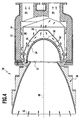
- FIG. 1 A first embodiment of a solar radiation receiver according to the invention is shown in FIG. 1 and designated there as a whole by 10.
- the Solar radiation receiver 10 is for example as a volumetric solar radiation receiver educated. It comprises a pressure vessel 12 with an inner insulation 14.
- a first flow guide 16 for Supply of auftropicendem gas (especially air) formed.
- a second flow guide 18 for the removal of heated gas (in particular air) formed.
- an absorber 20 is arranged in the pressure vessel 12.
- the heat to be heated Gas (working medium) is the absorber 20 via the first flow guide Supplied 16 and the working fluid can absorb heat at the absorber 20.
- the first flow guide 16 is so designed so that the absorber 20 can be acted upon surface to be heated with gas is.
- the working medium can absorb the absorber 20 for heat absorption flow through.
- an opening 22 is formed, at which an entrance window 24 is arranged.
- the entrance window 24 is curved and in particular dome-shaped with a foot portion 26 and a vertex area 28.
- the entrance window 24 which in particular made of quartz glass is, (concentrated) solar radiation can enter the pressure vessel 12 and heat the absorber 20 so as to heat the working medium again to be able to.
- the absorber 20 is in the pressure vessel 12 to the Entry window 24 arranged to a flat solar irradiation of the absorber 20 to reach.
- the entrance window 24 When carrying out the working medium through the pressure vessel 12 is this under a pressure of, for example, on the order of 7 bar or 15 bar.
- the entrance window 24 must withstand this pressure can. In the following, therefore, the entrance window 24 is also called Print window called.
- a secondary concentrator 30 for solar radiation Before the pressure vessel 12 is a secondary concentrator 30 for solar radiation arranged.
- About the secondary concentrator 30 can be in a primary concentrator concentrated solar radiation on the opening 22 and thus on concentrate the absorber 20.
- the primary concentrator is for example formed by one or more heliostats.
- the solar radiation (indicated in Figure 1 by the reference numeral 32) occurs through the entrance window 24 and strikes the absorber 20 and heats this on. This results in infrared radiation, which, inter alia, in Direction of the entrance window 24 is emitted. It has been shown that the most of the heat load of the entrance window 24 of the infrared radiation of the absorber 20 comes.
- infrared radiation shielding device 34 is arranged and designed so that it is transparent to solar radiation, d. H. Solar radiation to the absorber 20 passes. It is also designed that they infrared radiation, which comes from the absorber 20, from the entrance window 24 intercepts, d. H. this with respect to infrared radiation from the absorber 20 at least approximately shields. This is the heat load of the Entry window 24 greatly reduced.
- the infrared radiation shielding device 34 is opaque to infrared radiation. This can be achieved by absorbing this infrared radiation and / or to the rear, in the direction of the absorber 20, reflected.
- the infrared radiation shielding device 34 is arranged and configured that the entrance window 24 substantially over its entire inner side 36, which is located in an interior 38 of the pressure vessel 12 and the absorber 20 facing, covers, so that infrared radiation, which from the absorber 20th starting substantially from the entire inside 36 of the entrance window 24 is held.
- the infrared radiation shielding device designed as a shield window 40, which in particular coherently is.
- the shield window 40 may be integrally formed or made be composed of several segments.
- the shield window 40 made of quartz glass. Since the shield window 40 is the Entrance window 24 - passive - cool, will be in the following this shield window 40 also referred to as a cooling window.
- Quartz glass has the property of being permeable to solar radiation and infrared radiation to absorb. In the entrance window 24 thereby occurs Problem that this, if no infrared radiation shield 34th would be provided, is heated by the infrared radiation of the absorber 20. At high temperatures and in particular from about 800 ° C, the changes Quartz glass and it can lead to a devitrification process by formation of Crystals come. The rate of formation of the crystallites is dependent from the temperature. Devitrification leads to greater absorption of radiation and thus to a stronger heat load, which in turn to leads to greater mechanical stresses. These problems can be overcome the provision of the shield window 40 as an infrared radiation shield 34th greatly reduce.
- a shield window made of quartz glass 40 this absorbs the Infrared radiation coming from the absorber 20, the solar radiation, which via the entrance window 24 into the interior 38 of the pressure vessel 12th enters, is passed to the absorber 20.
- the shield window 40 is in the Pressure vessel 12 is arranged and thus forms no pressure window in this sense like the entrance window 24.
- the shield window 40 is formed, for example, that between this and the entrance window 24, a gap 42 is formed ( Figures 1 and 2).
- the Shield window 40 is preferably formed so that the gap 42 a having uniform thickness over the entrance window 24. Through the gap 42 can be via a - active - cooling device cooling fluid and in particular Perform air to both the entrance window 24 as the shield window 40, d. H. the cooling window to cool.
- the shield window 40 represents thereby a flow space for cooling the entrance window 24 ready, namely the gap 42.
- the shield window 40 in its vertex area 44, which is the vertex area 28 of the entrance window 24 adjacent, an opening 46 on.
- This opening 26 is coaxial arranged to an axis 48 of the entrance window 24.
- the entrance window 24 is preferably formed rotationally symmetrical to the axis 48 and the shield window 40 is preferably rotationally symmetrical to this axis 48 educated.
- a coupling-in area 50 for cooling fluid is provided in the gap 42.
- This coupling-in region 50 is in the case of that in FIGS. 1 and 2 embodiment shown at the foot portion 26 of the entrance window 24.
- a coupling ring 52 (FIG. 2) is provided, the cooling fluid (in particular air) can be fed.
- the coupling ring 52 has for this purpose a circulating fluid space 54. From this fluid space 54 starting from a plurality of fluid guides 56 ( Figures 2 and 3) is provided which in the gap 42 in a foot portion 58 of the shield window 40th to lead.
- the coupling ring 52 surrounds this foot area 58.
- the Fluid guides 56 are comprised of a swirl device 60 which ensures that in the gap 42 inflowing cooling fluid contains a twist and thus the velocity component is increased in the circumferential direction. Thereby the heat transfer to the cooling fluid is increased and the cooling effect will be improved.
- the swirling device 60 comprises the Fluid guides 56 channels 62, which open obliquely into the gap 42. Further are in a mouth region 64 between the channels 62 wall elements 66 arranged with sharp edges.
- the cooling fluid In the foot area is the flow rate under certain operating conditions the cooling fluid low, the cooling fluid is still cool. In the apex area, which is reached after flowing through the gap 42, the cooling fluid is heated, where there by a cross-sectional taper (relative to the axis 48) a higher flow velocity may be present.
- a cross-sectional taper relative to the axis 48
- the speed at the exit does not necessarily have to be larger than at the entrance, because in addition to the cross-sectional constriction also other Effects such as swirl and pressure losses can be effective.
- cooling fluid from the apex area out to the foot area d. H. Cooling fluid in the Vertex area is coupled.
- working medium flows over the first flow guide 16 to the absorber 20 to.
- (Heated) cooling fluid flows through the opening 46 from the gap 42 also the absorber 20th to.
- the cooling fluid flow thus forms a partial flow of the working medium, which then flows through the absorber 20 and via the second flow guide 18 is discharged.
- the cooling fluid flows mainly to a region of the absorber 20, which is the vertex region 28 of the entrance window 24 is opposite.
- the Cooling fluid flow in the gap 42 is superimposed on a vibration, d. H. an oscillation is impressed. It may be the problem that occurs in the gap 42, in particular in the apex region 28 of the entrance window 24 a Stagnation point of the cooling fluid flow is formed. In this stagnation point is under could no longer ensure sufficient cooling. By the Imprinting a vibration, the stagnation point can be oscillated.
- a gap 68 in the gap 42 is designated as a whole Device for generating vibrations provided.
- This device For example, includes a cover 70, with the periodically coupling of cooling fluid in the gap 42 can be covered and released. This means, if you look at a certain point of the coupling area 50 sets that is coupled via this periodic cooling fluid - thedeungsfluideinkopplung is periodically stopped or released periodically.
- the cover 70 is by means of a belt 72 formed, which has equally spaced openings 74.
- the ribbon 72 is in the fluid space 54 about an axis of rotation which coincides with the axis 48, stored rotatable or oscillatable.
- the band 72 is seated, for example in front of injection port openings 76 (FIG. 3) of the channels 62 Rotation of the belt 72, these Einkopplungsmündungsö Anlagennnenen 76th periodically enabled or disabled, so that via the corresponding channels 62 periodically cooling fluid can flow into the gap 42. Thereby leaves the cooling fluid flow in the gap 42 overlap an oscillation.
- the shield window 40 (the infrared radiation shielding device 34) forms a "heat shield" for the infrared radiation of the absorber 20, which based on the infrared radiation the entrance window 24 from the absorber 20 shields. Thereby a passive cooling of the entrance window 24 is effected.
- the shield window 40 is opaque to infrared radiation. Solar radiation, which passes through the entrance window 24 enters the interior 28 of the pressure vessel 12, but reaches the absorber 20, since the shield window 40 permeable to solar radiation is.
- the infrared radiation shielding device 34 acts as an absorber and in particular as a pre-absorber for the absorber 20th
- the heated cooling fluid becomes the flow guide 16 for working medium supplied, so that the corresponding cooling fluid mass flow a Partial flow of the working medium mass flow of the solar radiation receiver 10 is.
- the temperature of the entrance window can be 24 below a predetermined limit temperature such as 800 ° C, so as to keep devitrification processes low, for example.
- the cooling from the inside 36 produces a high temperature gradient prevented in the glass wall of the entrance window 24. This in turn mechanical stresses in the entrance window 24 are reduced.
- the entrance window 24 can be cooled homogeneously via the gap 42, so that it also mechanical stresses are reduced. Furthermore results An improved efficiency, as the heat of cooling used It stays in the solar radiation receiver and provides no loss represents.
- the heat transfer can be further increased.
- a second window i. H. of the shield window 40, lets the window function separate into the pressure-bearing entrance window 24 and the thermally loaded shield window 40, which refers to the outside space not pressure bearing.
- the shield window 40 in comparison to the inlet window 24 is not pressure-bearing
- this can also consist of several individual segments be constructed, it preferably be contiguous should.
- air can be used, which in a flow guide for a plurality of solar radiation receivers in a branching device is branched, which these solar radiation receivers upstream.
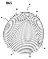
- the tube means 80 comprises a plurality of tubes 82 which are annular surround the entrance window 24 and at or near the interior 36 between the entrance window 24 and the absorber 20 are arranged.
- the Tubes 82 are transparent to solar radiation and in particular from Made of quartz glass.
- the tubes formed as tube rings 84 are arranged coaxially with the axis 48, wherein the diameter of the tube rings 84 decreases toward the absorber 20.
- the tube device 80 sits completely in the interior 38 of the pressure vessel 12th
- cooling fluid can flow and so that the entrance window 24 (and the tube device 80 itself) cool.
- the Pipe device 80 turn, the solar radiation to the absorber 20 out permeable, absorbs infrared radiation emanating from the absorber 20, and thereby shields the entrance window 24 from this infrared radiation from. It is beneficial if the pipe rings 84 adjacent pipe rings levels touch, so between adjacent pipe rings 84 no gap is present, get through the infrared radiation to the entrance window 24 can.
- manifolds and Distributor tubes 86 may be provided which, for example, transverse to the pipe rings 84 ( Figure 5) are arranged. These headers and manifolds 86 can serve at the same time as a framework 88 for holding the tube rings 84.
- a pipe structure is formed in a type of pipe ring hood 90, which position themselves in the interior 38 above the entrance window 24 leaves.
- the tube device 80 it is also possible in principle for the tube device 80 to be one or more spirally arranged tubes instead of with respect to theméungsfluid Adjust separate pipe rings 84.
- the tubes 82 of the tube device 80 with openings are provided, which are opposite to the inside 36 of the entrance window 24. These openings are preferably uniformly based on the inside 36 of the entrance window 24 distributed. About these openings can then Cooling fluid flow and the inside 36 of the inlet window 24 act and keep it cool The appropriate cooling fluid (In particular air) then forms a partial flow of the working medium, which flows through the pressure vessel 12.
- the appropriate cooling fluid In particular air
- the tube device 80 of the solar radiation receiver 78 absorbs the Coolable tube device 80, the infrared radiation of the absorber 20th
- a third embodiment which is shown schematically in Figure 6 and designated there as a whole by 92, is as an infrared radiation shielding device provided by a porous structure 94, over the entire Surface through "pores" can flow through a gaseous medium.
- the porous one Structure 94 is again transparent to solar radiation and opaque to Infrared radiation, which emanates from the absorber 20.
- the porous structure 94 is, for example, by means of glass fibers or glass hollow bodies (especially made of quartz glass).
- the porous one Structure 94 a woven or knitted fabric of glass fibers.
- the porous structure 94 which is designed like a hood, for example, is set in the interior 38 via the entrance window 24, wherein a gap 96 may be formed between the porous structure 94 and the entrance window 24 can.
- a gap 96 can be working medium of the pressure vessel 12 einkoppeln which flows through the porous structure 94 and the absorber 20th flows through. The flow takes place essentially over the entire Surface of the porous structure 94 as an infrared radiation shielding device 34th
- a branch 98 is arranged, via which a partial flow can branch off to working medium and the gap 96 can perform.
- This working medium flows through the gap 96, wherein it passes over a large area through the porous structure 94 and the absorber 20 (for heating by the solar radiation) is supplied.
- the partial flow of working medium thereby cools the entrance window 24 (and the porous structure 94 as infrared radiation shielding device 34).
- the entire working medium mass flow in the first flow guide 16 is coupled into the gap 96, d. H. that the total working medium mass flow through the porous structure 94 must before he gets to the absorber 20.
- the working medium then serves as Cooling medium for the entrance window 24 and the porous structure 94, and the porous structure 94 serves as a pre-absorber for the working medium.
- Under Circumstances can then be to a medium temperature module in a solar radiation receiver system dispense when passing through the porous structure 94 is provided for a sufficient preheating of the working medium. It is then a two-stage absorber is formed, the first step being the porous one Structure 94 and the second stage of the absorber 20th
- the porous structure 94 at which the working medium performed (asdeungsfluid) heats up, thus acts as an absorber, since a preheating of Working medium is performed.
- an entrance window 100 is provided, which an absorber 102 in a Interior of a pressure vessel facing is arranged.
- a free-jet device 104 is provided, which has a plurality of nozzles 107, via which an inner side 106 of the inlet window 100 can be acted upon with cooling fluid free-jet 108 is.
- Mouth openings 110 of the nozzles 107 are the inside 106 of the Facing the entrance window.
- the nozzles 107 are evenly distributed around the inside 106.
- Cooling fluid which is in particular working fluid, is on the Freistrahl Rhein 104 the inlet window 100 supplied. It then becomes one Partial flow diverted to (preferably not yet heated) working fluid, to generate the free jets 108.
- the absorber 102 is with breakthroughs 112 provided for the nozzles 107, so that cooling fluid to the nozzle 107th with its mouth openings 110 can be fed.
- a partial flow of cooling fluid from the Discharged working fluid and a supply of cooling fluid is connected to the (first) flow guide 16 coupled for working medium.
- a plurality of tubes 116 are in an interior space a pressure vessel on the inlet window 114 spaced apart.
- the tubes 116 are preferably transparent to solar radiation.
- These Tubes 116 are provided with openings which form an inner side 118 of the entrance window 114 facing. These openings form nozzle orifice openings fordefilfiluid, over which the inside 118 of the entrance window 114 blow with cooling fluid.
- the cooling fluid is in to the pipes 116 coupled.
Applications Claiming Priority (2)
| Application Number | Priority Date | Filing Date | Title |
|---|---|---|---|
| DE102004031917 | 2004-06-22 | ||
| DE102004031917.0A DE102004031917B4 (de) | 2004-06-22 | 2004-06-22 | Solarstrahlungsempfänger und Verfahren zur Kühlung eines Eintrittsfensters eines Solarstrahlungsempfängers |
Publications (2)
| Publication Number | Publication Date |
|---|---|
| EP1610073A2 true EP1610073A2 (fr) | 2005-12-28 |
| EP1610073A3 EP1610073A3 (fr) | 2013-01-16 |
Family
ID=34937484
Family Applications (1)
| Application Number | Title | Priority Date | Filing Date |
|---|---|---|---|
| EP05012940A Withdrawn EP1610073A3 (fr) | 2004-06-22 | 2005-06-16 | Récepteur solaire et procédé de refroidissement d'une fenêtre d'entrée d'un récepteur solaire |
Country Status (2)
| Country | Link |
|---|---|
| EP (1) | EP1610073A3 (fr) |
| DE (1) | DE102004031917B4 (fr) |
Cited By (19)
| Publication number | Priority date | Publication date | Assignee | Title |
|---|---|---|---|---|
| WO2009027986A2 (fr) * | 2007-08-30 | 2009-03-05 | Yeda Research And Development Company Ltd | Récepteurs solaires et systèmes correspondants |
| WO2010055439A2 (fr) * | 2008-11-13 | 2010-05-20 | Koninklijke Philips Electronics N.V. | Récepteur solaire s'utilisant dans un concentrateur d'énergie solaire |
| CN101592129B (zh) * | 2008-05-30 | 2011-05-11 | 彩熙太阳能环保技术(天津)有限公司 | 太阳能集热器 |
| GB2486209A (en) * | 2010-12-06 | 2012-06-13 | Alstom Technology Ltd | Solar receiver comprising a flow channel for a pressurised working fluid |
| DE102011113130B3 (de) * | 2011-09-14 | 2013-01-24 | Heraeus Quarzglas Gmbh & Co. Kg | Solarstrahlungsempfänger mit einem Eintrittsfenster aus Quarzglas |
| US8378280B2 (en) | 2007-06-06 | 2013-02-19 | Areva Solar, Inc. | Integrated solar energy receiver-storage unit |
| WO2012076344A3 (fr) * | 2010-12-06 | 2013-04-18 | Alstom Technology Ltd | Capteur solaire amélioré |
| WO2012076347A3 (fr) * | 2010-12-06 | 2013-05-10 | Alstom Technology Ltd. | Capteur solaire amélioré |
| WO2013142275A3 (fr) * | 2012-03-21 | 2014-01-03 | Wilson Solarpower Corporation | Systèmes d'unité de stockage multithermique, dispositifs de régulation de l'écoulement d'un fluide et récepteurs solaires à basse pression pour des systèmes d'énergie solaire ainsi que composants associés et utilisations de ces derniers |
| CN103644657A (zh) * | 2013-12-26 | 2014-03-19 | 哈尔滨工业大学 | 一种高温太阳能吸热器 |
| US8739512B2 (en) | 2007-06-06 | 2014-06-03 | Areva Solar, Inc. | Combined cycle power plant |
| US8807128B2 (en) | 2007-08-27 | 2014-08-19 | Areva Solar, Inc. | Linear fresnel solar arrays |
| US8960184B2 (en) | 2008-08-31 | 2015-02-24 | Yeda Research And Development Co. Ltd. | Solar receiver system |
| US9022020B2 (en) | 2007-08-27 | 2015-05-05 | Areva Solar, Inc. | Linear Fresnel solar arrays and drives therefor |
| US9726155B2 (en) | 2010-09-16 | 2017-08-08 | Wilson Solarpower Corporation | Concentrated solar power generation using solar receivers |
| WO2018205043A1 (fr) * | 2017-05-10 | 2018-11-15 | Synhelion Sa | Procédé pour faire fonctionner un récepteur et récepteur pour mettre en œuvre le procédé |
| CH713765A1 (de) * | 2017-05-10 | 2018-11-15 | Synhelion Sa C/O Avv Luca Tenchio | Verfahren zum Betrieb eines Receivers und Receiver zur Ausführung des Verfahrens. |
| WO2020093179A1 (fr) * | 2018-11-08 | 2020-05-14 | Synhelion Sa | Procédé pour faire fonctionner un récepteur et récepteur pour mettre en œuvre le procédé |
| US11415115B2 (en) * | 2017-12-22 | 2022-08-16 | Kaefer Isoliertechnik Gmbh & Co. Kg | Solar receiver for receiving solar rays and for heating a medium |
Families Citing this family (2)
| Publication number | Priority date | Publication date | Assignee | Title |
|---|---|---|---|---|
| US20120073567A1 (en) * | 2010-09-23 | 2012-03-29 | Roland Winston | Solar thermal concentrator apparatus, system, and method |
| WO2013021397A1 (fr) * | 2011-08-08 | 2013-02-14 | Sunborne Energy Technologies Pvt Ltd | Absorbeur pour système à énergie solaire concentrée |
Citations (10)
| Publication number | Priority date | Publication date | Assignee | Title |
|---|---|---|---|---|
| US4015582A (en) | 1974-05-31 | 1977-04-05 | The Regents Of The University Of Minnesota | Solar heat collector |
| US4135489A (en) | 1975-09-11 | 1979-01-23 | Sanders Associates, Inc. | Solar energy conversion system |
| US4164123A (en) | 1976-08-25 | 1979-08-14 | Smith Otto J M | Solar thermal electric power plant |
| US4472367A (en) | 1978-11-17 | 1984-09-18 | Geruldine Gibson | Method for the carbothermic reduction of metal oxides using solar energy |
| DE4234967A1 (de) | 1992-10-16 | 1994-04-21 | Schmidt Manfred Prof Dr Ing Ha | Solarkollektor |
| WO1996025633A1 (fr) | 1995-02-15 | 1996-08-22 | Yeda Research And Development Company Ltd. | Capteur solaire central a milieu de travail multiconstituants |
| DE19710986A1 (de) | 1997-03-17 | 1998-09-24 | Deutsch Zentr Luft & Raumfahrt | Druckkessel |
| JP2000252669A (ja) | 1999-02-26 | 2000-09-14 | Sony Corp | 冷却装置および電子機器 |
| DE10020322A1 (de) | 2000-04-26 | 2001-11-15 | Deutsch Zentr Luft & Raumfahrt | Strahlungsemfänger |
| US20020093791A1 (en) | 2001-01-18 | 2002-07-18 | Motorola, Inc. | System and method for cooling using an oscillatory impinging jet |
Family Cites Families (4)
| Publication number | Priority date | Publication date | Assignee | Title |
|---|---|---|---|---|
| US3934573A (en) | 1975-02-28 | 1976-01-27 | Dandini Alessandro O | Spherical system for the concentration and extraction of solar energy |
| US4479485A (en) * | 1982-04-14 | 1984-10-30 | The United States Of America As Represented By The United States Department Of Energy | Power efficiency for very high temperature solar thermal cavity receivers |
| IL100743A (en) | 1992-01-23 | 1994-11-28 | Yeda Res & Dev | Central solar collector |
| DE19713598C2 (de) | 1997-04-02 | 2000-05-25 | Deutsch Zentr Luft & Raumfahrt | Dämmsystem |
-
2004
- 2004-06-22 DE DE102004031917.0A patent/DE102004031917B4/de not_active Expired - Fee Related
-
2005
- 2005-06-16 EP EP05012940A patent/EP1610073A3/fr not_active Withdrawn
Patent Citations (10)
| Publication number | Priority date | Publication date | Assignee | Title |
|---|---|---|---|---|
| US4015582A (en) | 1974-05-31 | 1977-04-05 | The Regents Of The University Of Minnesota | Solar heat collector |
| US4135489A (en) | 1975-09-11 | 1979-01-23 | Sanders Associates, Inc. | Solar energy conversion system |
| US4164123A (en) | 1976-08-25 | 1979-08-14 | Smith Otto J M | Solar thermal electric power plant |
| US4472367A (en) | 1978-11-17 | 1984-09-18 | Geruldine Gibson | Method for the carbothermic reduction of metal oxides using solar energy |
| DE4234967A1 (de) | 1992-10-16 | 1994-04-21 | Schmidt Manfred Prof Dr Ing Ha | Solarkollektor |
| WO1996025633A1 (fr) | 1995-02-15 | 1996-08-22 | Yeda Research And Development Company Ltd. | Capteur solaire central a milieu de travail multiconstituants |
| DE19710986A1 (de) | 1997-03-17 | 1998-09-24 | Deutsch Zentr Luft & Raumfahrt | Druckkessel |
| JP2000252669A (ja) | 1999-02-26 | 2000-09-14 | Sony Corp | 冷却装置および電子機器 |
| DE10020322A1 (de) | 2000-04-26 | 2001-11-15 | Deutsch Zentr Luft & Raumfahrt | Strahlungsemfänger |
| US20020093791A1 (en) | 2001-01-18 | 2002-07-18 | Motorola, Inc. | System and method for cooling using an oscillatory impinging jet |
Cited By (45)
| Publication number | Priority date | Publication date | Assignee | Title |
|---|---|---|---|---|
| US8739512B2 (en) | 2007-06-06 | 2014-06-03 | Areva Solar, Inc. | Combined cycle power plant |
| US8378280B2 (en) | 2007-06-06 | 2013-02-19 | Areva Solar, Inc. | Integrated solar energy receiver-storage unit |
| US9022020B2 (en) | 2007-08-27 | 2015-05-05 | Areva Solar, Inc. | Linear Fresnel solar arrays and drives therefor |
| US8807128B2 (en) | 2007-08-27 | 2014-08-19 | Areva Solar, Inc. | Linear fresnel solar arrays |
| WO2009027986A3 (fr) * | 2007-08-30 | 2010-01-14 | Yeda Research And Development Company Ltd | Récepteurs solaires et systèmes correspondants |
| US20100206298A1 (en) * | 2007-08-30 | 2010-08-19 | Yeda Research And Development Company Ltd. | Solar receivers and systems thereof |
| WO2009027986A2 (fr) * | 2007-08-30 | 2009-03-05 | Yeda Research And Development Company Ltd | Récepteurs solaires et systèmes correspondants |
| CN101592129B (zh) * | 2008-05-30 | 2011-05-11 | 彩熙太阳能环保技术(天津)有限公司 | 太阳能集热器 |
| US8960184B2 (en) | 2008-08-31 | 2015-02-24 | Yeda Research And Development Co. Ltd. | Solar receiver system |
| WO2010055439A2 (fr) * | 2008-11-13 | 2010-05-20 | Koninklijke Philips Electronics N.V. | Récepteur solaire s'utilisant dans un concentrateur d'énergie solaire |
| WO2010055439A3 (fr) * | 2008-11-13 | 2011-05-05 | Koninklijke Philips Electronics N.V. | Récepteur solaire s'utilisant dans un concentrateur d'énergie solaire |
| US20110220095A1 (en) * | 2008-11-13 | 2011-09-15 | Koninklijke Philips Electronics N.V. | Solar receiver for use in a solar energy concentrator |
| CN111473530A (zh) * | 2010-09-16 | 2020-07-31 | 威尔逊太阳能公司 | 使用太阳能接收器的太阳能发电系统及其相关装置和方法 |
| US9726155B2 (en) | 2010-09-16 | 2017-08-08 | Wilson Solarpower Corporation | Concentrated solar power generation using solar receivers |
| US10280903B2 (en) | 2010-09-16 | 2019-05-07 | Wilson 247Solar, Inc. | Concentrated solar power generation using solar receivers |
| US11242843B2 (en) | 2010-09-16 | 2022-02-08 | 247Solar Inc. | Concentrated solar power generation using solar receivers |
| WO2012076344A3 (fr) * | 2010-12-06 | 2013-04-18 | Alstom Technology Ltd | Capteur solaire amélioré |
| US9719496B2 (en) | 2010-12-06 | 2017-08-01 | Alstrom Technology Ltd. | Solar receiver, method of cooling a solar receiver and a power generation system |
| GB2486209A (en) * | 2010-12-06 | 2012-06-13 | Alstom Technology Ltd | Solar receiver comprising a flow channel for a pressurised working fluid |
| CN103392100A (zh) * | 2010-12-06 | 2013-11-13 | 阿尔斯通技术有限公司 | 改进的太阳能接收器 |
| US20130263595A1 (en) * | 2010-12-06 | 2013-10-10 | Alstom Technology Ltd | Solar receiver, method of cooling a solar receiver and a power generation system |
| US9869302B2 (en) | 2010-12-06 | 2018-01-16 | General Electric Technology Gmbh | Solar receiver |
| CN103339448A (zh) * | 2010-12-06 | 2013-10-02 | 阿尔斯通技术有限公司 | 太阳能接收器、冷却太阳能接收器的方法和功率生成系统 |
| CN103229001A (zh) * | 2010-12-06 | 2013-07-31 | 阿尔斯通技术有限公司 | 改进的太阳能接收器 |
| WO2012076347A3 (fr) * | 2010-12-06 | 2013-05-10 | Alstom Technology Ltd. | Capteur solaire amélioré |
| CN103229001B (zh) * | 2010-12-06 | 2016-09-07 | 通用电器技术有限公司 | 改进的太阳能接收器 |
| CN103339448B (zh) * | 2010-12-06 | 2016-09-21 | 通用电器技术有限公司 | 太阳能接收器、冷却太阳能接收器的方法和功率生成系统 |
| US10024577B2 (en) | 2011-09-14 | 2018-07-17 | Heraeus Quarzglas Gmbh & Co. Kg | Solar radiation receiver having an entry window made of quartz glass and method for producing an entry window |
| DE102011113130B3 (de) * | 2011-09-14 | 2013-01-24 | Heraeus Quarzglas Gmbh & Co. Kg | Solarstrahlungsempfänger mit einem Eintrittsfenster aus Quarzglas |
| WO2013037877A1 (fr) | 2011-09-14 | 2013-03-21 | Heraeus Quarzglas Gmbh & Co. Kg | Récepteur solaire pourvu d'une fenêtre d'entrée en verre de quartz, et procédé de fabrication d'une fenêtre d'entrée |
| CN104334978B (zh) * | 2012-03-21 | 2017-05-17 | 威尔逊太阳能公司 | 用于太阳能发电系统的多储热单元系统、流体流动控制装置和低压太阳能接收器、以及其相关部件和用途 |
| WO2013142275A3 (fr) * | 2012-03-21 | 2014-01-03 | Wilson Solarpower Corporation | Systèmes d'unité de stockage multithermique, dispositifs de régulation de l'écoulement d'un fluide et récepteurs solaires à basse pression pour des systèmes d'énergie solaire ainsi que composants associés et utilisations de ces derniers |
| CN107588560A (zh) * | 2012-03-21 | 2018-01-16 | 威尔逊太阳能公司 | 太阳能接收器、发电系统和流体流动控制装置 |
| CN104334978A (zh) * | 2012-03-21 | 2015-02-04 | 威尔逊太阳能公司 | 用于太阳能发电系统的多储热单元系统、流体流动控制装置和低压太阳能接收器、以及其相关部件和用途 |
| CN112797649A (zh) * | 2012-03-21 | 2021-05-14 | 威尔逊太阳能公司 | 太阳能接收器、发电系统和流体流动控制装置 |
| US10876521B2 (en) | 2012-03-21 | 2020-12-29 | 247Solar Inc. | Multi-thermal storage unit systems, fluid flow control devices, and low pressure solar receivers for solar power systems, and related components and uses thereof |
| CN110260534A (zh) * | 2012-03-21 | 2019-09-20 | 威尔逊太阳能公司 | 太阳能接收器、发电系统和流体流动控制装置 |
| CN103644657B (zh) * | 2013-12-26 | 2015-08-19 | 哈尔滨工业大学 | 一种高温太阳能吸热器 |
| CN103644657A (zh) * | 2013-12-26 | 2014-03-19 | 哈尔滨工业大学 | 一种高温太阳能吸热器 |
| CN110720017A (zh) * | 2017-05-10 | 2020-01-21 | 信赫利恩有限公司 | 用于运行接收器的方法和用于实施该方法的接收器 |
| CH713765A1 (de) * | 2017-05-10 | 2018-11-15 | Synhelion Sa C/O Avv Luca Tenchio | Verfahren zum Betrieb eines Receivers und Receiver zur Ausführung des Verfahrens. |
| WO2018205043A1 (fr) * | 2017-05-10 | 2018-11-15 | Synhelion Sa | Procédé pour faire fonctionner un récepteur et récepteur pour mettre en œuvre le procédé |
| US11415115B2 (en) * | 2017-12-22 | 2022-08-16 | Kaefer Isoliertechnik Gmbh & Co. Kg | Solar receiver for receiving solar rays and for heating a medium |
| WO2020093179A1 (fr) * | 2018-11-08 | 2020-05-14 | Synhelion Sa | Procédé pour faire fonctionner un récepteur et récepteur pour mettre en œuvre le procédé |
| CN113227670A (zh) * | 2018-11-08 | 2021-08-06 | 信赫利恩有限公司 | 用于运行接收器的方法和用于实施该方法的接收器 |
Also Published As
| Publication number | Publication date |
|---|---|
| EP1610073A3 (fr) | 2013-01-16 |
| DE102004031917A1 (de) | 2006-01-12 |
| DE102004031917B4 (de) | 2021-07-29 |
Similar Documents
| Publication | Publication Date | Title |
|---|---|---|
| EP1610073A2 (fr) | Récepteur solaire et procédé de refroidissement d'une fenêtre d'entrée d'un récepteur solaire | |
| DE19710986A1 (de) | Druckkessel | |
| EP0174699B1 (fr) | Procédé et appareil de fabrication d'une fibre optique avec une gaine synthétique | |
| EP0105563B2 (fr) | Appareil pour l'étirage d'une fibre optique à partir d'une préforme solide consistant de SiO2 et du SiO2 dopé | |
| DE2012949A1 (de) | Wandkonstruktion und Luftzufuhrlöcher für ein Gasturbinentriebwerk | |
| EP1746363A2 (fr) | Récepteur solaire et procédé de contrôle et/ou de régulation de la répartition du débit et/ou de la compensation de température dans un récepteur solaire | |
| DE3316167C2 (fr) | ||
| DE3002887A1 (de) | Wirbelroehrenanordnung mit vereisungsschutz und schalldaempfung | |
| DE4223779C1 (de) | Solaranlage mit einem Lufterhitzer und Luftrückführung | |
| DE102016002128B4 (de) | Einen Lichtstrahl absorbierender optischer Absorber | |
| EP0108298B1 (fr) | Condenseur de turbine avec au minimum un conduit de dérivation de vapeur entrant dans le dôme | |
| DE102013221888B3 (de) | Receiver für Solarenergiegewinnungsanlagen | |
| DE69826537T2 (de) | Vorrichtung zur Aushärtung von Fasern mit wenigstens zwei Aushärtungsstufen die getrennt sind durch einen Abkühlvorgang | |
| DE19743428A1 (de) | Solarempfänger | |
| DE102006053804B4 (de) | Flanschverbindung | |
| DE10251458B4 (de) | Kryostat | |
| EP3538823B1 (fr) | Récepteur doté de modules absorbeurs | |
| WO2017144251A1 (fr) | Récepteur pour installations de production d'énergie solaire | |
| DE102013221889B4 (de) | Receiver für Solarenergiegewinnungsanlagen | |
| EP3728964A1 (fr) | Récepteur solaire permettant de recueillir des rayons de soleil et de chauffer un milieu | |
| EP2589909A2 (fr) | Dispositif de chauffage ou de séchage de matériaux allongés | |
| WO2024056658A1 (fr) | Module solaire-thermique | |
| WO2020019087A1 (fr) | Procédé d'isolation d'une unité de traitement et unité de traitement dotée d'une zone d'isolation | |
| DE102016110319A1 (de) | Verfahren und Vorrichtung zur Erzeugung von Ammoniak in einem Abgasstrom einer Verbrennungskraftmaschine | |
| DE102016208215B4 (de) | Receiver für Solarenergiegewinnungsanlagen |
Legal Events
| Date | Code | Title | Description |
|---|---|---|---|
| PUAI | Public reference made under article 153(3) epc to a published international application that has entered the european phase |
Free format text: ORIGINAL CODE: 0009012 |
|
| AK | Designated contracting states |
Kind code of ref document: A2 Designated state(s): AT BE BG CH CY CZ DE DK EE ES FI FR GB GR HU IE IS IT LI LT LU MC NL PL PT RO SE SI SK TR |
|
| AX | Request for extension of the european patent |
Extension state: AL BA HR LV MK YU |
|
| RAP1 | Party data changed (applicant data changed or rights of an application transferred) |
Owner name: DEUTSCHES ZENTRUM FUER LUFT- UND RAUMFAHRT E.V. |
|
| PUAL | Search report despatched |
Free format text: ORIGINAL CODE: 0009013 |
|
| AK | Designated contracting states |
Kind code of ref document: A3 Designated state(s): AT BE BG CH CY CZ DE DK EE ES FI FR GB GR HU IE IS IT LI LT LU MC NL PL PT RO SE SI SK TR |
|
| AX | Request for extension of the european patent |
Extension state: AL BA HR LV MK YU |
|
| RIC1 | Information provided on ipc code assigned before grant |
Ipc: F24J 2/07 20060101AFI20121212BHEP Ipc: F24J 2/46 20060101ALI20121212BHEP |
|
| 17P | Request for examination filed |
Effective date: 20130624 |
|
| RBV | Designated contracting states (corrected) |
Designated state(s): AT BE BG CH CY CZ DE DK EE ES FI FR GB GR HU IE IS IT LI LT LU MC NL PL PT RO SE SI SK TR |
|
| AKX | Designation fees paid |
Designated state(s): AT BE BG CH CY CZ DE DK EE ES FI FR GB GR HU IE IS IT LI LT LU MC NL PL PT RO SE SI SK TR |
|
| 17Q | First examination report despatched |
Effective date: 20131010 |
|
| GRAP | Despatch of communication of intention to grant a patent |
Free format text: ORIGINAL CODE: EPIDOSNIGR1 |
|
| INTG | Intention to grant announced |
Effective date: 20170119 |
|
| STAA | Information on the status of an ep patent application or granted ep patent |
Free format text: STATUS: THE APPLICATION IS DEEMED TO BE WITHDRAWN |
|
| 18D | Application deemed to be withdrawn |
Effective date: 20170530 |