EP1610073A2 - Solar receiver and method for cooling the entrance window of a solar receiver - Google Patents
Solar receiver and method for cooling the entrance window of a solar receiver Download PDFInfo
- Publication number
- EP1610073A2 EP1610073A2 EP05012940A EP05012940A EP1610073A2 EP 1610073 A2 EP1610073 A2 EP 1610073A2 EP 05012940 A EP05012940 A EP 05012940A EP 05012940 A EP05012940 A EP 05012940A EP 1610073 A2 EP1610073 A2 EP 1610073A2
- Authority
- EP
- European Patent Office
- Prior art keywords
- solar radiation
- receiver according
- absorber
- radiation receiver
- cooling fluid
- Prior art date
- Legal status (The legal status is an assumption and is not a legal conclusion. Google has not performed a legal analysis and makes no representation as to the accuracy of the status listed.)
- Withdrawn
Links
Images


Classifications
-
- F—MECHANICAL ENGINEERING; LIGHTING; HEATING; WEAPONS; BLASTING
- F24—HEATING; RANGES; VENTILATING
- F24S—SOLAR HEAT COLLECTORS; SOLAR HEAT SYSTEMS
- F24S70/00—Details of absorbing elements
- F24S70/10—Details of absorbing elements characterised by the absorbing material
-
- F—MECHANICAL ENGINEERING; LIGHTING; HEATING; WEAPONS; BLASTING
- F24—HEATING; RANGES; VENTILATING
- F24S—SOLAR HEAT COLLECTORS; SOLAR HEAT SYSTEMS
- F24S20/00—Solar heat collectors specially adapted for particular uses or environments
- F24S20/20—Solar heat collectors for receiving concentrated solar energy, e.g. receivers for solar power plants
-
- F—MECHANICAL ENGINEERING; LIGHTING; HEATING; WEAPONS; BLASTING
- F24—HEATING; RANGES; VENTILATING
- F24S—SOLAR HEAT COLLECTORS; SOLAR HEAT SYSTEMS
- F24S40/00—Safety or protection arrangements of solar heat collectors; Preventing malfunction of solar heat collectors
- F24S40/50—Preventing overheating or overpressure
- F24S40/55—Arrangements for cooling, e.g. by using external heat dissipating means or internal cooling circuits
-
- Y—GENERAL TAGGING OF NEW TECHNOLOGICAL DEVELOPMENTS; GENERAL TAGGING OF CROSS-SECTIONAL TECHNOLOGIES SPANNING OVER SEVERAL SECTIONS OF THE IPC; TECHNICAL SUBJECTS COVERED BY FORMER USPC CROSS-REFERENCE ART COLLECTIONS [XRACs] AND DIGESTS
- Y02—TECHNOLOGIES OR APPLICATIONS FOR MITIGATION OR ADAPTATION AGAINST CLIMATE CHANGE
- Y02E—REDUCTION OF GREENHOUSE GAS [GHG] EMISSIONS, RELATED TO ENERGY GENERATION, TRANSMISSION OR DISTRIBUTION
- Y02E10/00—Energy generation through renewable energy sources
- Y02E10/40—Solar thermal energy, e.g. solar towers
Abstract
Description
Die Erfindung betrifft einen Solarstrahlungsempfänger, umfassend einen Druckkessel und einen in dem Druckkessel angeordneten Absorber für Solarstrahlung, wobei ein Arbeitsmedium durch den Druckkessel zur Wärmeaufnahme am Absorber führbar ist, und ein am Druckkessel angeordnetes Eintrittsfenster für die Solarstrahlung.The invention relates to a solar radiation receiver, comprising a Pressure vessel and an absorber arranged in the pressure vessel for solar radiation, wherein a working medium through the pressure vessel for heat absorption can be guided on the absorber, and arranged on the pressure vessel entrance window for the solar radiation.
Die Erfindung betrifft ferner ein Verfahren zur Kühlung eines Eintrittsfensters eines Solarstrahlungsempfängers, welcher einen mit Solarstrahlung beaufschlagbaren Absorber aufweist.The invention further relates to a method for cooling an entrance window a solar radiation receiver, which can be acted upon by a solar radiation Absorber has.
Solarstrahlungsempfänger dienen dazu, solarthermisch erzeugte Wärme an ein gasförmiges Arbeitsmedium wie Luft weiterzugeben. Bei einem geschlossenen Solarstrahlungsempfänger ist in einem Druckkessel ein Absorber angeordnet, welcher solarthermisch aufgeheizt wird. Die Strahlung tritt durch das Eintrittsfenster, welches insbesondere gewölbt ist, in den Druckkessel. Dieses Eintrittsfenster ist grundsätzlich einer hohen Wärmebelastung ausgesetzt.Solar radiation receiver serve to solar thermal generated heat to a to pass on gaseous working medium such as air. In a closed Solar radiation receiver is arranged in a pressure vessel, an absorber, which is heated solar-thermally. The radiation passes through the entrance window, which is in particular curved, in the pressure vessel. This entrance window is basically exposed to high heat load.
Solarstrahlungsempfänger sind beispielsweise in der DE 197 10 986 A1 und der DE 100 20 322 A1 beschrieben. Solar radiation receiver are described for example in DE 197 10 986 A1 and DE 100 20 322 A1 describes.
Aus der US 4,135,489 ist ein Solar-Energiekonversionssystem bekannt, welches einen Absorber aufweist. Es ist eine Drei-Fenster-Konfiguration vorgesehen, wobei ein Fenster als "Diode" wirkt, welche Infrarotstrahlung zurück zu dem Absorber reflektiert.From US 4,135,489 a solar energy conversion system is known which having an absorber. There is a three-window configuration provided one window acts as a "diode" which returns infrared radiation reflected to the absorber.
Der Erfindung liegt die Aufgabe zugrunde, einen Solarstrahlungsempfänger bereitzustellen, bei dem die Wärmebelastung des Eintrittsfensters minimiert ist.The invention is based on the object, a solar radiation receiver to provide, in which minimizes the heat load of the entrance window is.
Diese Aufgabe wird bei dem eingangs genannten Solarstrahlungsempfänger erfindungsgemäß dadurch gelöst, daß zwischen dem Eintrittsfenster und dem Absorber eine Infrarotstrahlungsschildeinrichtung angeordnet ist, welche für Solarstrahlung durchlässig ist und welche vom Absorber ausgehende Infrarotstrahlung abfängt und daß die Infrarotstrahlungsschildeinrichtung so angeordnet und ausgebildet ist, daß vom Absorber ausgehende Infrarotstrahlung vom Eintrittsfenster abgeschirmt ist, um den Wärmeeintrag an das Eintrittsfenster von dem Innenraum des Druckkessels her zu verringern.This object is achieved in the case of the aforementioned solar radiation receiver According to the invention solved in that between the entrance window and the Absorber an infrared radiation shielding device is arranged, which for Solar radiation is permeable and which emanating from the absorber infrared radiation intercepts and that the infrared radiation shielding device arranged so and is formed so that emanating from the absorber infrared radiation from Entrance window is shielded to the heat input to the entrance window to reduce from the interior of the pressure vessel ago.
Es hat sich gezeigt, daß der Hauptteil der Wärmebelastung des Eintrittsfensters von Infrarotstrahlung kommt, die vom Absorber aufgrund dessen Aufheizung durch Solarstrahlung emittiert wird. Durch die Infrarotstrahlungsschildeinrichtung läßt sich das Eintrittsfenster zumindest partiell gegenüber dieser Infrarotstrahlung abschirmen. It has been found that the main part of the heat load of the entrance window from infrared radiation comes from the absorber due to that Heating is emitted by solar radiation. By the infrared radiation shielding device the entrance window can be at least partially opposite shield this infrared radiation.
Die in dem Druckkessel angeordnete Infrarotstrahlungsschildeinrichtung ist opak für die Infrarotstrahlung des Absorbers und transparent für die Solarstrahlung. Dadurch ist sichergestellt, daß Solarstrahlung, welche durch das Eintrittsfenster in den Druckkessel tritt, den Absorber aufheizen kann.The arranged in the pressure vessel infrared radiation shielding device is opaque to the infrared radiation of the absorber and transparent to the solar radiation. This ensures that solar radiation, which by the Entrance window enters the pressure vessel, the absorber can heat up.
Durchlässigkeit für Solarstrahlung ist dabei so zu verstehen, daß ein wesentlicher Teil der durch das Eintrittsfenster eintretenden Solarstrahlung den Absorber erreicht. Opak ist so zu verstehen, daß ein wesentlicher Teil der vom Absorber kommenden Infrarotstrahlung bezogen auf das Eintrittsfenster abgefangen wird.Permeability to solar radiation is understood to mean that an essential Part of entering through the entrance window solar radiation absorber reached. Opak is to be understood that an essential part of the Absorber incoming infrared radiation based on the entrance window intercepted becomes.
Durch die erfindungsgemäße Lösung ist der Wärmeeintrag an das Eintrittsfenster von dem Innenraum des Druckkessels her stark verringert. Dadurch wird das Entstehen eines hohen Temperaturgradienten über die Wandstärke des Eintrittsfensters verhindert. Dadurch wiederum lassen sich mechanische Spannungen im Eintrittsfenster verringern.The inventive solution is the heat input to the entrance window greatly reduced from the interior of the pressure vessel ago. Thereby will be the emergence of a high temperature gradient across the wall thickness of the entrance window prevented. This in turn allows mechanical Reduce voltages in the entrance window.
Aufgrund geringerer Abstrahlungsverluste und Konvektionsverluste am Eintrittsfenster läßt sich der Wirkungsgrad des Solarstrahlungsempfängers erhöhen.Due to lower radiation losses and convection losses at the entrance window can increase the efficiency of the solar radiation receiver.
Weiterhin sind höhere Auslaßtemperaturen für den Solarstrahlungsempfänger möglich, so daß der Wirkungsgrad verbessert werden kann.Furthermore, higher outlet temperatures for the solar radiation receiver possible, so that the efficiency can be improved.
Durch die erfindungsgemäße Lösung läßt sich eine Funktionstrennung bezüglich des Eintrittsfensters durchführen; das Eintrittsfenster ist drucktragend. Die Infrarotstrahlungsschildeinrichtung ist derjenige Teil des Solarstrahlungsempfängers, welcher der stärksten Wärmebelastung ausgesetzt ist. Diese Wärmebelastung wird von dem Eintrittsfenster abgenommen.The inventive solution can be a function separation with respect of the entrance window; the entrance window is pressure-bearing. The Infrared radiation shielding means is that part of the solar radiation receiver, which is exposed to the strongest heat load. These Heat load is removed from the entrance window.
Es ist dabei auch grundsätzlich möglich, daß die Infrarotstrahlungsschildeinrichtung als Absorber bzw. Vorabsorber dient, durch den sich Arbeitsmedium aufheizen läßt.It is also possible in principle that the infrared radiation shielding device serves as absorber or pre-absorber, through which working medium to heat up.
Es kann eine Kühlungsfluidströmung vorgesehen sein (wobei das Kühlungsfluid Arbeitsmedium sein kann), über die sich das Eintrittsfenster und die Infrarotstrahlungsschildeinrichtung kühlen lassen, wobei das aufgeheizte Kühlungsfluid als Arbeitsmedium eingesetzt werden kann.There may be provided a cooling fluid flow (the cooling fluid Can be working medium) over which the entrance window and the infrared radiation shielding device let cool, with the heated cooling fluid can be used as a working medium.
Insbesondere ist die Infrarotstrahlungsschildeinrichtung so angeordnet und ausgebildet, daß vom Absorber ausgehende Infrarotstrahlung vom Eintrittsfenster abgeschirmt ist. Dadurch ist die Wärmebelastung des Eintrittsfensters aufgrund Infrarotstrahlung, welche vom Absorber ausgeht, stark verringert.In particular, the infrared radiation shielding device is arranged and designed so that emanating from the absorber infrared radiation from the entrance window is shielded. This is the heat load of the entrance window due to infrared radiation, which emanates from the absorber, greatly reduced.
Ganz besonders vorteilhaft ist es, wenn die Infrarotstrahlungsschildeinrichtung so angeordnet und ausgebildet ist, daß vom Absorber ausgehende Infrarotstrahlung bezogen auf die Gesamtfläche des Eintrittsfensters abgefangen wird. Dadurch läßt sich eine Infrarotstrahlungsbeaufschlagung des Eintrittsfensters über dessen gesamte Innenseite, welche in einem Innenraum des Druckkessels liegt, verhindern oder zumindest stark verringern.It is particularly advantageous if the infrared radiation shielding device is arranged and designed so that emanating from the absorber infrared radiation is intercepted based on the total area of the entrance window. This allows an infra-red radiation exposure of the entrance window over its entire inside, which in an interior of the pressure vessel lies, prevents or at least greatly reduces.
Üblicherweise werden Eintrittsfenster aus Quarzglas hergestellt. Bei hohen Temperaturen tritt dabei das Problem der Entglasung durch Kristallitbildung auf. Durch die erfindungsgemäße Lösung läßt sich das Eintrittsfenster effektiv kühlen, zumindest in dem Sinne, daß Infrarotstrahlung vom Eintrittsfenster abgeschirmt wird. Dadurch läßt sich die Temperatur des Eintrittsfensters unterhalb einer Temperatur von ca. 800°C bis 850°C halten. Entglasungsvorgänge sind bei diesen Temperaturen relativ langsam, d. h. finden nicht beschleunigt statt.Usually entrance windows are made of quartz glass. At high Temperatures thereby the problem of devitrification by crystallite formation on. By the solution according to the invention, the entrance window can be effectively cool, at least in the sense that infrared radiation from the entrance window is shielded. This allows the temperature of the entrance window Keep below a temperature of approx. 800 ° C to 850 ° C. Entglasungsvorgänge are relatively slow at these temperatures, d. H. do not find it accelerated instead of.
Günstig ist es, wenn die Infrarotstrahlungsschildeinrichtung aus Quarzglas hergestellt ist. Quarzglas ist durchgängig für Solarstrahlung und absorbiert Infrarotstrahlung. Dies ist gerade das Problem, wenn Infrarotstrahlung vom Absorber auf das Eintrittsfenster aus Quarzglas gelangt, da sich dieses aufgrund der absorbierten Infrarotstrahlung aufheizt. Wenn die Infrarotstrahlungsschildeinrichtung aus Quarzglas hergestellt ist, dann absorbiert diese vom Absorber ausgehende Infrarotstrahlung, während sie Solarstrahlung zum Absorber durchläßt. Die absorbierte Infrarotstrahlung, die zu einer Aufheizung der Infrarotstrahlungsschildeinrichtung führt, gelangt dann nicht mehr zum Eintrittsfenster, so daß dieses weniger stark thermisch belastet ist.It is favorable if the infrared radiation shielding device made of quartz glass is made. Quartz glass is consistent for solar radiation and absorbs infrared radiation. This is just the problem when infrared radiation from the absorber on the entrance window made of quartz glass, as this due to heats the absorbed infrared radiation. When the infrared radiation shielding device made of quartz glass, then absorbs them from the absorber outgoing infrared radiation while sending solar radiation to the absorber passes. The absorbed infrared radiation leading to a heating the infrared radiation shielding device leads, then no longer Entrance window, so that it is less thermally stressed.
In Kombination mit der Infrarotstrahlungsschildeinrichtung oder unabhängig davon ist es günstig, wenn eine Kühlungseinrichtung zur Kühlung des Eintrittsfensters an einer dem Absorber zugewandten Innenseite vorgesehen ist. Durch die Kühlungseinrichtung läßt sich die Temperatur des Eintrittsfensters so niedrig halten, daß Entglasungsvorgänge mit sehr kleiner Rate stattfinden. Durch die Kühlungseinrichtung läßt sich ferner die Infrarotstrahlungsschildeinrichtung kühlen. In combination with the infrared radiation shielding device or independent of which it is favorable if a cooling device for cooling the entrance window is provided on an inner side facing the absorber. By the cooling device, the temperature of the entrance window can be so keep down that devitrification processes take place at a very low rate. By the cooling device can also be the infrared radiation shielding device cool.
Beispielsweise ist eine Anströmung der Innenseite des Eintrittsfensters mit Kühlungsfluid vorgesehen. Als Kühlungsfluid wird vorzugsweise Luft eingesetzt. Das Kühlungsfluid kann einer Strömungsführung für Arbeitsmedium abgezweigt werden, wobei eine Abzweigung innerhalb des Druckkessels oder außerhalb des Druckkessels grundsätzlich möglich ist.For example, a flow is the inside of the entrance window with Cooling fluid provided. The cooling fluid used is preferably air. The cooling fluid can be branched off from a flow guide for working medium be, with a branch within the pressure vessel or outside the pressure vessel is basically possible.
Es kann vorgesehen sein, daß zwischen dem Eintrittsfenster und der Infrarotstrahlungsschildeinrichtung ein Spalt gebildet ist, durch den Kühlungsfluid führbar ist. Kühlungsfluid, welches diesen Spalt durchströmt und dabei die Innenseite des Eintrittsfensters beaufschlägt, führt Wärme vom Eintrittsfenster ab, d. h. kühlt dieses. Durch das Kühlungsfluid kann ferner Wärme von der Infrarotstrahlungsschildeinrichtung abgeführt werden und diese gekühlt werden.It can be provided that between the entrance window and the infrared radiation shielding device a gap is formed by the cooling fluid is feasible. Cooling fluid which flows through this gap and thereby the Applied to the inside of the entrance window, leads heat from the entrance window off, d. H. cool this. By the cooling fluid can also heat from the Infrared radiation shielding are removed and these are cooled.
Bei einem Ausführungsbeispiel ist in der Infrarotstrahlungsschildeinrichtung mindestens eine Öffnung vorgesehen, durch die Kühlungsfluid aus dem Spalt zum Absorber strömen kann. Das Kühlungsfluid kann sich dann mit dem Arbeitsmedium im Druckkessel mischen, so daß der Kühlungsfluidstrom ein Teilstrom des Arbeitsmediumstroms ist. Das Kühlungsfluid wird in dem Spalt aufgeheizt und aufgeheiztes Kühlungsfluid wird dann dem Absorber zugeführt. In diesem Sinne ist die Infrarotstrahlungsschildeinrichtung ein Vorabsorber, da dort Kühlungsfluid als Arbeitsmedium vorgeheizt wird.In one embodiment, in the infrared radiation shielding device at least one opening provided by the cooling fluid from the gap can flow to the absorber. The cooling fluid may then react with the working fluid mix in the pressure vessel, so that the cooling fluid flow is a partial flow the working medium flow is. The cooling fluid is heated in the gap and heated cooling fluid is then supplied to the absorber. In In this sense, the infrared radiation shielding device is a pre-absorber since there cooling fluid is preheated as the working medium.
Es ist dabei grundsätzlich möglich, daß eine Mehrzahl von Öffnungen in der Infrarotstrahlungsschildeinrichtung angeordnet sind, welche insbesondere gleichmäßig über diese verteilt sind. Es ist auch möglich, daß beispielsweise nur eine einzige Öffnung vorgesehen ist. It is in principle possible that a plurality of openings in the Infrared radiation shielding device are arranged, which in particular evenly distributed over these. It is also possible that, for example only a single opening is provided.
Bei einer Variante einer Ausführungsform ist eine Öffnung in einem Scheitelbereich der Infrarotstrahlungsschildeinrichtung bezogen auf das Eintrittsfenster angeordnet. Über diese Öffnung kann aufgeheiztes Kühlungsfluid dem Absorber zuströmen. Kühlungsfluid läßt sich dann in den Spalt in einen Fußbereich einkoppeln und aus dem Scheitelbereich aus dem Spalt abführen. Dadurch läßt sich eine gute homogene Kühlwirkung erzielen; bei der Einkopplung in den Fußbereich des Spalts ist das Kühlungsfluid noch kühl und weist bei bestimmten Betriebsbedingungen eine geringere Geschwindigkeit auf. Wenn das Kühlungsfluid den Scheitelbereich erreicht, dann ist es aufgeheizt. Durch eine höhere Geschwindigkeit im Scheitelbereich (aufgrund Querschnittsverringerung im Spalt) ist die Geschwindigkeit bei bestimmten Betriebsbedingungen dort höher, so daß sich über den gesamten Spaltbereich eine gleichmäßige Kühlungswirkung ergibt.In a variant of an embodiment, an opening is in a vertex area the infrared radiation shielding device with respect to the entrance window arranged. Heated cooling fluid can reach the absorber via this opening flow to. Cooling fluid can then be in the gap in a foot area couple in and remove from the apex area from the gap. Thereby leaves to achieve a good homogeneous cooling effect; at the coupling in the Foot portion of the gap, the cooling fluid is still cool and points at certain Operating conditions at a lower speed. When the cooling fluid reaches the peak area, then it is heated. By a higher Speed in the apex area (due to reduction in cross section in the gap) is the speed under certain operating conditions there higher, so that over the entire gap area a uniform cooling effect results.
Insbesondere ist die Öffnung koaxial zu einer Achse des Eintrittsfensters ausgerichtet. Dadurch lassen sich symmetrische Verhältnisse erzielen, so daß eine räumlich homogene Kühlwirkung gewährleistbar ist.In particular, the opening is aligned coaxially with an axis of the entrance window. As a result, symmetrical conditions can be achieved, so that a spatially homogeneous cooling effect can be ensured.
Bei einer weiteren Variante einer Ausführungsform ist die Infrarotstrahlungsschildeinrichtung mit einer Mehrzahl von Öffnungen versehen, so daß Kühlungsfluid aus dem Spalt über einen großen Flächenbereich der Infrarotstrahlungsschildeinrichtung zum Absorber strömen kann. Bei dieser Variante läßt sich eine gleichmäßige Durchströmung der Infrarotstrahlungsschildeinrichtung erzielen, um so eine gleichmäßige Kühlwirkung zu erzielen und eine gleichmäßige Aufheizung des Kühlungsfluids (welches dann als Arbeitsmedium eingesetzt werden kann) zu erzielen. Die Infrarotstrahlungsschildeinrichtung läßt sich so effektiv als Vorabsorber einsetzen. Weiterhin läßt sich so die Ausbildung von Staupunkten verhindern.In a further variant of an embodiment, the infrared radiation shielding device provided with a plurality of openings, so that cooling fluid from the gap over a large area of the infrared radiation shielding device can flow to the absorber. In this variant leaves there is a uniform flow through the infrared radiation shielding device achieve a uniform cooling effect and a uniform Heating the cooling fluid (which then as a working medium can be used) to achieve. The infrared radiation shielding device can be used effectively as a pre-absorber. Furthermore, so can the Prevent the formation of stagnation points.
Grundsätzlich kann eine Einkopplung von Kühlungsfluid in den Spalt in einem Fußbereich des Spalts vorgesehen sein. Dadurch kann sich mindestens bei bestimmten Betriebsbedingungen eine homogene Kühlwirkung ergeben, wenn im Fußbereich des Spalts das noch kühle Kühlungsfluid eine geringe Geschwindigkeit aufweist und im Scheitelbereich das aufgeheizte Kühlungsfluid eine höhere Geschwindigkeit aufweist.Basically, a coupling of cooling fluid in the gap in a Foot area of the gap may be provided. This can be at least certain Operating conditions give a homogeneous cooling effect, if in Foot of the gap, the still cool cooling fluid a low speed and in the apex area, the heated cooling fluid has a higher Speed.
Es kann alternativ auch eine Einkopplung von Kühlungsfluid in einen Scheitelbereich des Spalts vorgesehen sein.Alternatively, it may also be a coupling of cooling fluid in a vertex area be provided of the gap.
Günstig ist es, wenn dem Spalt eine Dralleinrichtung zur Verdrallung von in dem Spalt strömenden Kühlungsfluid zugeordnet ist. Durch die Verdrallung läßt sich der Wärmeübergang von den Spalt begrenzenden Wänden (des Eintrittsfensters und der Infrarotstrahlungsschildeinrichtung) auf das Kühlungsfluid verbessern. Eine solche Dralleinrichtung läßt sich auf einfache Weise herstellen und in den Strahlungsempfänger integrieren. Vorzugsweise ist dabei die Dralleinrichtung in der Nähe eines Einkopplungsbereichs von Kühlungsfluid in den Spalt angeordnet. Eine solche Dralleinrichtung läßt sich auf einfache Weise herstellen und insbesondere muß der Spalt selber als Zwischenraum zwischen dem Eintrittsfenster und der Infrarotstrahlungsschildeinrichtung nicht modifiziert werden. It is advantageous if the gap is a swirl device for twisting in associated with the gap flowing cooling fluid. By the twisting can the heat transfer from the gap bounding walls (the entrance window and the infrared radiation shielding device) on the cooling fluid improve. Such a swirl device can be produced in a simple manner and integrate into the radiation receiver. Preferably, the Swirl device in the vicinity of a coupling region of cooling fluid in arranged the gap. Such a swirl device can be easily manufacture and in particular must the gap itself as a gap between the entrance window and the infrared radiation shielding device not modified become.
Es kann auch günstig sein, wenn dem Spalt eine Einrichtung zur Erzeugung von Schwingungen in der Kühlungsfluidströmung im Spalt zugeordnet ist. Es kann grundsätzlich das Problem entstehen, daß sich ein oder mehrere Staupunkte ausbilden. Ein Staupunkt bildet sich vorzugsweise im Scheitelbereich des Eintrittsfensters aus. An der Stelle eines Staupunkts ist das Eintrittsfenster stärker thermisch belastet und insbesondere punktuell belastet. Wenn der Kühlungsfluidströmung eine Schwingung bzw. Oszillation überlagert wird, dann läßt sich ein solcher Staupunkt zumindest oszillierend verschieben, so daß nicht eine einzige Stelle des Eintrittsfensters punktuell belastet wird. Die mittlere Belastung ist dann verringert.It may also be beneficial if the gap is a device for generating is associated with vibrations in the cooling fluid flow in the gap. It In principle, the problem may arise that one or more stagnation points form. A stagnation point preferably forms in the apex area of the entrance window. In the place of a stagnation point is the entrance window more thermally stressed and especially punctually loaded. If the Cooling fluid flow is superimposed on a vibration or oscillation, then can such a stagnation point at least oscillate, so that not a single point of the entrance window is punctually punctured. The average load is then reduced.
Beispielsweise umfaßt die Einrichtung zur Erzeugung von Schwingungen eine Abdeckung, mit der periodisch die Einkopplung von Kühlungsfluid in den Spalt freigebbar ist. Über entsprechende Steuerung der Abdeckung und insbesondere Bewegung der Abdeckung läßt sich periodisch Kühlungsfluid einkoppeln und dadurch der Kühlungsfluidströmung eine Schwingung bzw. Oszillation überlagern.For example, the vibration generating means comprises one Cover, with which periodically the coupling of cooling fluid into the gap is releasable. Over appropriate control of the cover and in particular Movement of the cover can be coupled periodically cooling fluid and thereby the cooling fluid flow, a vibration or oscillation overlap.
Beispielsweise umfaßt die Einrichtung zur Erzeugung von Schwingungen ein Band mit Öffnungen, welches in einem Fußbereich des Spalts drehbar oder oszillierbar angeordnet ist. Wenn die Öffnungen Einlaßkanälen gegenüberliegen, dann ist die Einlaßströmung von Kühlungsfluid in den Spalt freigegeben. Ansonsten sind die Einlaßmündungen abgedeckt. Durch Oszillation bzw. Drehung des Bands erfolgt eine periodische Freigabe, welche zu einer Schwingungsüberlagerung führt. For example, the vibration generating means comprises Band with openings, which rotatable in a foot area of the gap or is arranged to be oscillatable. When the openings face inlet channels, then the inlet flow of cooling fluid is released into the gap. Otherwise the inlet mouths are covered. By oscillation or rotation of the belt is a periodic release, which to a Vibration overlap leads.
Bei einem Ausführungsbeispiel ist an oder in der Nähe der Innenseite des Eintrittsfensters eine Rohreinrichtung angeordnet, in welcher Kühlungsfluid strömt. Über das in der Rohreinrichtung strömende Kühlungsfluid läßt sich die Rohreinrichtung selber und das Eintrittsfenster kühlen. In der Rohreinrichtung läßt sich die Kühlungsfluidströmung "fangen". Dadurch läßt sich ein Austritt von Kühlungsfluid in den Innenraum des Druckkessels verhindern. Es ist aber auch grundsätzlich möglich, daß die Rohreinrichtung mit Öffnungen versehen ist, über die Kühlungsfluid der Innenseite des Eintrittsfensters zuströmen kann.In one embodiment, at or near the inside of the entrance window arranged a tube means, in which cooling fluid flows. About the flowing in the tube means cooling fluid can be Cool the pipe device itself and the inlet window. In the tube device the cooling fluid flow can be "caught". This can be an exit prevent cooling fluid from entering the interior of the pressure vessel. But it is also possible in principle that the tube device provided with openings is to flow over the cooling fluid to the inside of the entrance window can.
Bei einer Ausführungsform ist eine Freistrahleinrichtung vorgesehen, über welche die Innenseite des Eintrittsfensters mit Kühlungsfluid-Freistrahlen beaufschlagbar ist. Dadurch läßt sich das Eintrittsfenster kühlen. Die Kühlung erfolgt dabei von einem Innenraum des Druckkessels her. Von diesem Innenraum her ist das Eintrittsfenster auch am stärksten wärmebelastet. Es wird dann die Ausbildung eines großen Temperaturgradienten über die Wand des Eintrittsfensters entgegengewirkt.In one embodiment, a free-jet device is provided, via which the inside of the entrance window with cooling fluid free jets acted upon is. This allows the entrance window to cool. The cooling takes place doing so from an interior of the pressure vessel ago. From this interior the entrance window is also the strongest heat load. It will then be the Formation of a large temperature gradient across the wall of the entrance window counteracted.
Beispielsweise umfaßt die Freistrahleinrichtung eine Mehrzahl von Düsen, deren Mündungsöffnung der Innenseite des Eintrittsfensters zugewandt sind. Das Eintrittsfenster läßt sich dadurch mit den Freistrahlen an Kühlungsfluid beaufschlagen. Die Düsen sind dabei vorzugsweise in einem Durchbruch des Absorbers angeordnet bzw. werden über solche Durchbrüche mit Kühlungsfluid versorgt. For example, the free-jet device comprises a plurality of nozzles, whose mouth opening facing the inside of the entrance window. The entrance window can be characterized with the free jets of cooling fluid apply. The nozzles are preferably in an opening of the Absorber arranged or are such breakthroughs with cooling fluid provided.
Es kann auch vorgesehen sein, daß die Freistrahleinrichtung eine Mehrzahl von Rohren umfaßt, welche Düsenöffnungen aufweisen. Die Rohre sind insbesondere transparent. In diese Rohre wird Kühlungsfluid eingekoppelt, welches dann aus diesen austreten kann und als Freistrahl das Eintrittsfenster beaufschlagen kann. Die Rohre müssen nicht unbedingt als Infrarotstrahlungsschildeinrichtung für das Eintrittsfenster ausgebildet sein.It can also be provided that the free-jet device comprises a plurality of Includes tubes having nozzle openings. The pipes are in particular transparent. In these tubes cooling fluid is coupled, which then exit from these and act as a free jet the entrance window can. The tubes do not necessarily have to be used as an infrared radiation shielding device be formed for the entrance window.
Vorzugsweise sind die Rohre fächerförmig an oder in der Nähe der Innenseite des Eintrittsfensters angeordnet, um eine gleichmäßige Freistrahlbeaufschlagung der Innenseite des Eintrittsfensters zu erreichen.Preferably, the tubes are fan-shaped at or near the inside the entrance window arranged to a uniform free jet to reach the inside of the entrance window.
Es kann vorgesehen sein, daß eine Kühlungsfluidführung an eine Strömungsführung für Arbeitsmedium in dem Druckkessel gekoppelt ist. Ein Kühlungsfluidstrom ist dann ein Teilstrom des Arbeitsmediumstroms.It can be provided that a cooling fluid guide to a flow guide is coupled for working fluid in the pressure vessel. A cooling fluid stream is then a partial flow of the working medium flow.
Es ist dabei grundsätzlich möglich, daß eine Abführung für Kühlungsfluid an die Strömungsführung für Arbeitsmedium gekoppelt ist. Aufgeheiztes Kühlungsfluid läßt sich dann als Arbeitsmedium einsetzen.It is in principle possible that a discharge for cooling fluid to the Flow guide for working medium is coupled. Heated cooling fluid can then be used as a working medium.
Es ist auch möglich, daß eine Zuführung für Kühlungsfluid an die Strömungsführung für Arbeitsmedium gekoppelt ist. Es läßt sich dann Arbeitsmedium und insbesondere noch nicht aufgeheiztes Arbeitsmedium als Kühlungsfluid einsetzen.It is also possible that a supply of cooling fluid to the flow guide coupled for working medium. It can then be working medium and in particular not yet heated working medium used as a cooling fluid.
Bei einer Ausführungsform ist die Infrarotstrahlungsschildeinrichtung als zusammenhängendes Schildfenster ausgebildet, welches zwischen dem Eintrittsfenster und dem Absorber angeordnet ist. Das Schildfenster bildet ein Kühlfenster, welches die Infrarotstrahlung vom Eintrittsfenster abschirmt. Das Schildfenster ist in dem Innenraum des Druckkessels angeordnet und über das Eintrittsfenster gesetzt.In one embodiment, the infrared radiation shielding device is contiguous Shield window formed between the entrance window and the absorber is arranged. The shield window forms Cooling window, which shields the infrared radiation from the entrance window. The Shield window is located in the interior of the pressure vessel and over the Entry window set.
Es kann vorgesehen sein, daß die Infrarotstrahlungsschildeinrichtung einstückig ausgebildet ist oder aus einer Mehrzahl von Segmenten zusammengesetzt ist. Da das Schildfenster kein drucktragendes Teil ist (es ist im Innenraum des Solarstrahlungsempfängers angeordnet), ist es weniger starken Belastungen ausgesetzt bzw. die Folgen eines Bruchs des Schildfensters sind gegenüber den Folgen eines Bruchs des Eintrittsfensters weniger schlimm.It can be provided that the infrared radiation shielding device in one piece is formed or composed of a plurality of segments is. Since the shield window is not a pressure-bearing part (it is in the interior the solar radiation receiver arranged), it is less heavy loads exposed or the consequences of a breach of the shield window are less serious against the consequences of a break in the entrance window.
Beispielsweise sind das Eintrittsfenster und das Schildfenster gleichmäßig beabstandet angeordnet und ausgebildet. Ein Spalt zwischen dem Eintrittsfenster und dem Schildfenster hat dann über den gesamten Bereich des Eintrittsfenster eine gleichmäßige Dicke.For example, the entrance window and the shield window are equally spaced arranged and trained. A gap between the entrance window and the shield window then has over the entire area of the entrance window a uniform thickness.
Bei einem weiteren Ausführungsbeispiel umfaßt die Infrarotstrahlungsschildeinrichtung ein für Solarstrahlung transparentes Rohr oder eine Mehrzahl von transparenten Rohren, welche zwischen dem Eintrittsfenster und dem Absorber angeordnet sind. In den Rohren selber läßt sich Kühlungsfluid führen. Die Rohre sind durchlässig für Solarstrahlung und absorbieren Infrarotstrahlung.In a further embodiment, the infrared radiation shielding device comprises a transparent to solar radiation tube or a plurality of transparent tubes, which between the entrance window and the absorber are arranged. Cooling fluid can be carried in the tubes themselves. The Tubes are permeable to solar radiation and absorb infrared radiation.
Es kann dabei vorgesehen sein, daß das oder die Rohre um das Eintrittsfenster bezogen auf eine Achse des Eintrittsfensters liegen. Dadurch läßt sich Infrarotstrahlung vom Absorber vom Eintrittsfenster abschirmen und weiterhin läßt sich eine gleichmäßige (passive) Kühlungswirkung für das Eintrittsfenster erreichen. It may be provided that the one or more tubes around the entrance window relative to an axis of the entrance window. This allows infrared radiation Shield off the absorber from the entrance window and continue to leave to achieve a uniform (passive) cooling effect for the entrance window.
Es ist grundsätzlich vorgesehen, daß das Kühlungsfluid in den Rohren "gefangen" strömt. Dadurch lassen sich die Rohre kühlen. Es ist aber auch denkbar, daß das oder die Rohre mit der Innenwand des Eintrittsfensters zugewandten Öffnungen versehen sind. Durch diese kann dann Kühlungsfluid austreten und die Innenseite des Eintrittsfensters beaufschlagen. Es lassen sich dann die Rohre und das Eintrittsfenster kühlen.It is basically provided that the cooling fluid in the pipes "caught" streams. This allows the pipes to cool. It is also conceivable that the one or more tubes facing the inner wall of the entrance window Openings are provided. Through this can then cooling fluid exit and apply the inside of the entrance window. Let it Then cool the pipes and the entrance window.
Günstig ist es, wenn mittels Sammelrohren und/oder Verteilerrohren eine Rohrstruktur gebildet ist. Über die Sammelrohre/Verteilerrohre läßt sich Kühlungsfluid abführen bzw. zuführen. Diese können so angeordnet sein, daß sie ein Gerüst für die Rohre bilden und damit eine Rohrstruktur-Einheit bilden, welche beispielsweise haubenförmig ausgestaltet ist.It is favorable if by means of headers and / or distribution pipes a Pipe structure is formed. About the headers / distribution pipes can be cooling fluid remove or feed. These can be arranged so that they form a framework for the tubes and thus form a tube structure unit, which is designed, for example, hood-shaped.
Bei einer weiteren Ausführungsform ist die Infrarotstrahlungsschildeinrichtung als poröse Struktur ausgebildet, welche für Solarstrahlung durchlässig ist und für Infrarotstrahlung opak ist. Durch die poröse Struktur läßt sich über einen großen Flächenbereich Kühlungsfluid abführen.In a further embodiment, the infrared radiation shielding device designed as a porous structure which is permeable to solar radiation and is opaque to infrared radiation. The porous structure can be over a dissipate large surface area cooling fluid.
Insbesondere ist die Infrarotstrahlungsschildeinrichtung dann aus einem transparenten Material hergestellt. Beispielsweise ist die Infrarotstrahlungsschildeinrichtung aus (Glas-)Fasern und/oder (Glas-)Hohlkörpern hergestellt.In particular, the infrared radiation shielding device is then made of a made of transparent material. For example, the infrared radiation shielding device made of (glass) fibers and / or (glass) hollow bodies.
Die poröse Struktur kann als Gewebe oder Gewirke ausgebildet sein, um eine Infrarotstrahlungsschildeinrichtung bereitzustellen, durch die Kühlungsfluid strömen kann (über die "Poren"), welche Infrarotstrahlung absorbiert und welche Solarstrahlung zum Absorber durchläßt. The porous structure may be formed as a woven or knitted fabric to a To provide infrared radiation shielding device, by the cooling fluid can flow (via the "pores"), which absorbs infrared radiation and which Solar radiation to the absorber lets through.
Insbesondere ist die Infrarotstrahlungsschildeinrichtung als Absorber bzw. Vorabsorber für Infrarotstrahlung ausgebildet. Ein Kühlungsfluid läßt sich dann aufheizen und als Arbeitsmedium weiter einsetzen. Das Kühlungsfluid als Arbeitsmedium wird dem Absorber zur endgültigen Aufheizung zugeführt.In particular, the infrared radiation shielding device as absorber or Pre-absorber for infrared radiation formed. A cooling fluid can then be heat up and continue to use as a working medium. The cooling fluid as a working medium is fed to the absorber for final heating.
Der Erfindung liegt ferner die Aufgabe zugrunde, ein Verfahren der eingangs genannten Art so zu verbessern, daß die Wärmebeaufschlagung des Eintrittsfensters verringert ist.The invention is also based on the object, a method of the above mentioned type to improve so that the heat application of the entrance window is reduced.
Diese Aufgabe wird bei dem eingangs genannten Verfahren erfindungsgemäß dadurch gelöst, daß vom Absorber in Richtung Eintrittsfenster ausgehende Infrarotstrahlung abgefangen wird.This object is according to the invention in the aforementioned method solved by emanating from the absorber in the direction of the entrance window infrared radiation is intercepted.
Das erfindungsgemäße Verfahren weist die bereits im Zusammenhang mit dem erfindungsgemäßen Solarstrahlungsempfänger geschilderten Vorteile auf.The inventive method already has in connection with the solar radiation receiver according to the invention described advantages.
Es handelt sich dabei um eine passive Kühlung.It is a passive cooling system.
Es kann zusätzlich oder alternativ auch eine aktive Kühlung vorgesehen sein, bei der das Eintrittsfenster an einer dem Absorber zugewandten Innenseite mittels Kühlungsfluid gekühlt wird. Es kann dabei eine direkte Kühlungsfluidbeaufschlagung der Innenseite erfolgen oder eine "gefangene" Kühlungsfluidströmung zur Wärmeabfuhr vorgesehen sein. It may additionally or alternatively also be provided an active cooling, in which the entrance window on an inside facing the absorber is cooled by means of cooling fluid. It can be a direct Kühlflufluidabeaufschlagung the inside or a "trapped" cooling fluid flow be provided for heat dissipation.
Bei einer Ausführungsform ist ein Kühlungsfluidstrom ein Teilstrom eines Stroms an Arbeitsmedium des Solarstrahlungsempfängers, wobei das Arbeitsmedium am Absorber Wärme aufnimmt.In one embodiment, a cooling fluid flow is a partial flow of a Electricity to working medium of the solar radiation receiver, wherein the working medium absorbs heat at the absorber.
Es kann auch vorgesehen sein, daß das Arbeitsmedium des Solarstrahlungsempfängers, welches am Absorber Wärme aufnimmt, als Kühlungsfluid eingesetzt wird. Vorzugsweise wird Arbeitsmedium als Kühlungsfluid eingesetzt, bevor dieses den Absorber durchströmt.It can also be provided that the working medium of the solar radiation receiver, which absorbs heat at the absorber, used as a cooling fluid becomes. Preferably, working fluid is used as the cooling fluid before this flows through the absorber.
Grundsätzlich ist es möglich, daß ein Teilstrom an Arbeitsmedium in einer Infrarotstrahlungsschildeinrichtung vorgewärmt wird und diese damit als Vorabsorber dient. Es kann auch vorgesehen sein, daß der gesamte Arbeitsmediummassenstrom durch eine zwischen dem Eintrittsfenster und dem Absorber angeordnete Infrarotstrahlungsschildeinrichtung geführt wird, wobei beispielsweise eine poröse Struktur die Infrarotstrahlungsschildeinrichtung bildet. Der Massenstrom an Arbeitsmedium, welcher dem Absorber zugeführt wird, muß dann zuvor die Infrarotstrahlungsschildeinrichtung durchströmen. Das Arbeitsmedium kann dort Wärme aufnehmen, so daß die Infrarotstrahlungsschildeinrichtung als Vorabsorber dient. Solarstrahlungsempfängersysteme weisen üblicherweise eine Mehrzahl von Solarstrahlungsempfängern auf, wie beispielsweise ein Niedertemperaturmodul, ein Mitteltemperaturmodul und ein Hochtemperaturmodul. Wenn dafür gesorgt wird, daß das Arbeitsmedium die Infrarotstrahlungsschildeinrichtung vollständig durchströmt und dort Wärme aufnimmt, dann kann unter Umständen auf ein Mitteltemperaturmodul verzichtet werden. In principle, it is possible that a partial stream of working medium in an infrared radiation shielding device is preheated and thus used as a pre-absorber serves. It can also be provided that the entire working medium mass flow through a between the entrance window and the absorber arranged infrared radiation shielding device is guided, wherein For example, a porous structure forms the infrared radiation shielding device. The mass flow of working medium, which fed to the absorber is, must then first flow through the infrared radiation shielding device. The working medium can absorb heat there, so that the infrared radiation shielding device serves as a pre-absorber. Solar radiation receiver systems typically have a plurality of solar radiation receivers on, such as a low-temperature module, a medium-temperature module and a high temperature module. If it is ensured that the working medium the infrared radiation shield completely flows through and there absorbs heat, then may be on a medium temperature module be waived.
Die nachfolgende Beschreibung bevorzugter Ausführungsbeispiele dient im Zusammenhang mit der Zeichnung der näheren Erläuterung der Erfindung. Es zeigen:
- Figur 1
- eine Querschnittsdarstellung eines ersten Ausführungsbeispiels eines erfindungsgemäßen Solarstrahlungsempfängers;
- Figur 2
- eine perspektivische Teildarstellung eines Ausführungsbeispiels eines Eintrittsfensters und eines Kühlfensters;
- Figur 3
- eine vergrößerte Darstellung eines Einkopplungsbereichs für Kühlungsfluid bei dem Eintrittsfenster gemäß Figur 2;
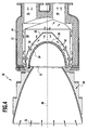
- Figur 4
- eine Schnittansicht eines zweiten Ausführungsbeispiels eines erfindungsgemäßen Solarstrahlungsempfängers;
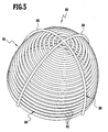
- Figur 5
- eine perspektivische Darstellung eines Ausführungsbeispiels einer Infrarotstrahlungsschildeinrichtung;
- Figur 6
- eine Schnittdarstellung eines dritten Ausführungsbeispiels eines erfindungsgemäßen Solarstrahlungsempfängers;
- Figur 7
- eine Teildarstellung (gezeigt sind ein Eintrittsfenster und teilweise ein Absorber) eines vierten Ausführungsbeispiels eines erfindungsgemäßen Solarstrahlungsempfängers und
- Figur 8
- ein Eintrittsfenster in perspektivischer Ansicht und eine Kühlungseinrichtung bei einem fünften Ausführungsbeispiel eines erfindungsgemäßen Solarstrahlungsempfängers.
- FIG. 1
- a cross-sectional view of a first embodiment of a solar radiation receiver according to the invention;
- FIG. 2
- a partial perspective view of an embodiment of an entrance window and a cooling window;
- FIG. 3
- an enlarged view of a coupling-in area for cooling fluid at the entrance window of Figure 2;
- FIG. 4
- a sectional view of a second embodiment of a solar radiation receiver according to the invention;
- FIG. 5
- a perspective view of an embodiment of an infrared radiation shielding device;
- FIG. 6
- a sectional view of a third embodiment of a solar radiation receiver according to the invention;
- FIG. 7
- a partial view (shown are an entrance window and partially an absorber) of a fourth embodiment of a solar radiation receiver according to the invention and
- FIG. 8
- an entrance window in a perspective view and a cooling device in a fifth embodiment of a solar radiation receiver according to the invention.
Ein erstes Ausführungsbeispiel eines erfindungsgemäßen Solarstrahlungsempfängers
ist in Figur 1 gezeigt und dort als Ganzes mit 10 bezeichnet. Der
Solarstrahlungsempfänger 10 ist beispielsweise als volumetrischer Solarstrahlungsempfänger
ausgebildet. Er umfaßt einen Druckkessel 12 mit einer Innenisolierung
14. In dem Druckkessel 12 ist eine erste Strömungsführung 16 zur
Zuführung von aufzuheizendem Gas (insbesondere Luft) gebildet. Ferner ist
eine zweite Strömungsführung 18 zur Abführung von aufgeheiztem Gas
(insbesondere Luft) gebildet.A first embodiment of a solar radiation receiver according to the invention
is shown in FIG. 1 and designated there as a whole by 10. Of the
In dem Druckkessel 12 ist ein Absorber 20 angeordnet. Das aufzuheizende
Gas (Arbeitsmedium) wird dem Absorber 20 über die erste Strömungsführung
16 zugeführt und das Arbeitsmedium kann an dem Absorber 20 Wärme aufnehmen.
Im Bereich des Absorbers 20 ist die erste Strömungsführung 16 so
ausgebildet, daß der Absorber 20 flächig mit aufzuheizendem Gas beaufschlagbar
ist. Das Arbeitsmedium kann den Absorber 20 zur Wärmeaufnahme
durchströmen.In the
Arbeitsmedium, welches den Absorber 20 durchströmt hat, wird dann über die
zweite Strömungsführung 18 abgeführt.Working medium, which has flowed through the
In dem Druckkessel 12 ist eine Öffnung 22 gebildet, an welcher ein Eintrittsfenster
24 angeordnet ist. Das Eintrittsfenster 24 ist gewölbt und insbesondere
kuppelförmig ausgebildet mit einem Fußbereich 26 und einem Scheitelbereich
28. Durch das Eintrittsfenster 24, welches insbesondere aus Quarzglas hergestellt
ist, kann (konzentrierte) Solarstrahlung in den Druckkessel 12 eintreten
und den Absorber 20 aufheizen, um so wiederum das Arbeitsmedium aufheizen
zu können. Der Absorber 20 ist dazu in dem Druckkessel 12 um das
Eintrittsfenster 24 angeordnet, um eine flächige Solarstrahlungsbeaufschlagung
des Absorbers 20 zu erreichen.In the
Bei der Durchführung des Arbeitsmediums durch den Druckkessel 12 steht
dieses unter einem Druck, der beispielsweise in der Größenordnung von 7 bar
oder 15 bar liegen kann. Das Eintrittsfenster 24 muß diesem Druck standhalten
können. Im folgenden wird deshalb das Eintrittsfenster 24 auch als
Druckfenster bezeichnet.When carrying out the working medium through the
In der DE 100 20 322 A1 ist ein Strahlungsempfänger beschrieben, bei dem
das Eintrittsfenster 24 mittels einer Lagervorrichtung an einer Druckkesselwand
derart beweglich gelagert ist, daß mechanische Spannungen im Eintrittsfenster
24 durch Bewegung des Eintrittsfensters 24 relativ zu der Druckkesselwand
abbaubar sind. Auf dieses Dokument wird ausdrücklich Bezug genommen.In
In der DE 197 10 986 A1 ist ein Druckkessel 12 offenbart, bei welchem die
erste Strömungsführung 16 (Einlaßstromführung) und die zweite Strömungsführung
18 (Auslaßstromführung) derart miteinander gekoppelt sind, daß ein
Teilstrom aus der Auslaßstromführung in die Einlaßstromführung rückführbar
ist. Dazu sind entsprechende Durchlaßmittel vorgesehen. Auf dieses Dokument
wird ebenfalls ausdrücklich Bezug genommen. In DE 197 10 986 A1 discloses a
Vor dem Druckkessel 12 ist ein Sekundärkonzentrator 30 für Solarstrahlung
angeordnet. Über den Sekundärkonzentrator 30 läßt sich in einem Primärkonzentrator
konzentrierte Solarstrahlung auf die Öffnung 22 und damit auf
den Absorber 20 konzentrieren. Der Primärkonzentrator ist beispielsweise
durch einen oder mehrere Heliostate gebildet.Before the
Die Solarstrahlung (in Figur 1 durch das Bezugszeichen 32 angedeutet) tritt
durch das Eintrittsfenster 24 hindurch und trifft auf den Absorber 20 und heizt
diesen auf. Dadurch entsteht Infrarotstrahlung, die unter anderem auch in
Richtung des Eintrittsfensters 24 abgestrahlt wird. Es hat sich gezeigt, daß der
überwiegende Teil der Wärmebelastung des Eintrittsfensters 24 von der Infrarotstrahlung
des Absorbers 20 stammt.The solar radiation (indicated in Figure 1 by the reference numeral 32) occurs
through the
Erfindungsgemäß ist eine als Ganzes mit 34 bezeichnete Infrarotstrahlungsschildeinrichtung
vorgesehen, welche zwischen dem Eintrittsfensters 24 und
dem Absorber 20 angeordnet ist. Diese Infrarotstrahlungsschildeinrichtung 34
ist so angeordnet und ausgebildet, daß sie transparent für Solarstrahlung ist,
d. h. Solarstrahlung zum Absorber 20 durchläßt. Sie ist ferner so ausgebildet,
daß sie Infrarotstrahlung, welche vom Absorber 20 stammt, vom Eintrittsfenster
24 abfängt, d. h. dieses bezüglich Infrarotstrahlung von dem Absorber
20 zumindest näherungsweise abschirmt. Dadurch ist die Wärmebelastung des
Eintrittsfensters 24 stark verringert.According to the invention as a whole with 34 designated infrared radiation shielding device
provided, which between the
Die Infrarotstrahlungsschildeinrichtung 34 ist opak für Infrarotstrahlung. Dies
läßt sich dadurch erreichen, daß diese Infrarotstrahlung absorbiert und/oder
nach hinten, in Richtung des Absorbers 20, reflektiert. The infrared
Die Infrarotstrahlungsschildeinrichtung 34 ist so angeordnet und ausgebildet,
daß das Eintrittsfenster 24 im wesentlichen über seine gesamte Innenseite 36,
welche in einem Innenraum 38 des Druckkessels 12 liegt und dem Absorber
20 zugewandt ist, abdeckt, so daß Infrarotstrahlung, welche vom Absorber 20
ausgeht, im wesentlichen von der gesamten Innenseite 36 des Eintrittsfensters
24 abgehalten wird.The infrared
Bei dem ersten Ausführungsbeispiel 10 ist die Infrarotstrahlungsschildeinrichtung
als Schildfenster 40 ausgebildet, welches insbesondere zusammenhängend
ist. Das Schildfenster 40 kann einstückig ausgebildet sein oder aus
mehreren Segmenten zusammengesetzt sein. Insbesondere ist das Schildfenster
40 aus Quarzglas hergestellt. Da über das Schildfenster 40 sich das
Eintrittsfenster 24 - passiv - kühlen läßt, wird im folgenden dieses Schildfenster
40 auch als Kühlfenster bezeichnet.In the
Quarzglas hat die Eigenschaft, für Solarstrahlung durchlässig zu sein und Infrarotstrahlung
zu absorbieren. Bei dem Eintrittsfenster 24 tritt dadurch das
Problem auf, daß dieses, wenn keine Infrarotstrahlungsschildeinrichtung 34
vorgesehen wäre, durch die Infrarotstrahlung des Absorbers 20 erhitzt wird.
Bei hohen Temperaturen und insbesondere ab ca. 800°C verändert sich das
Quarzglas und es kann zu einem Entglasungsvorgang durch Bildung von
Kristalliten kommen. Die Bildungsgeschwindigkeit der Kristallite ist dabei abhängig
von der Temperatur. Entglasung führt zu einer größeren Strahlungsabsorption
und damit zu einer stärkeren Wärmebelastung, was wiederum zu
größeren mechanischen Spannungen führt. Diese Probleme lassen sich durch
das Vorsehen des Schildfensters 40 als Infrarotstrahlungsschildeinrichtung 34
stark verringern.Quartz glass has the property of being permeable to solar radiation and infrared radiation
to absorb. In the
Bei einem aus Quarzglas hergestellten Schildfenster 40 absorbiert dieses die
Infrarotstrahlung, welche vom Absorber 20 kommt, wobei die Solarstrahlung,
welche über das Eintrittsfenster 24 in den Innenraum 38 des Druckkessels 12
eintritt, zum Absorber 20 durchgelassen wird. Das Schildfenster 40 ist in dem
Druckkessel 12 angeordnet und bildet damit in diesem Sinne kein Druckfenster
wie das Eintrittsfenster 24.In a shield window made of
Das Schildfenster 40 ist beispielsweise so ausgebildet, daß zwischen diesem
und dem Eintrittsfenster 24 ein Spalt 42 gebildet ist (Figuren 1 und 2). Das
Schildfenster 40 ist vorzugsweise so ausgebildet, daß der Spalt 42 eine
gleichmäßige Dicke über das Eintrittsfenster 24 aufweist. Durch den Spalt 42
läßt sich über eine - aktive - Kühlungseinrichtung Kühlungsfluid und insbesondere
Luft durchführen, um sowohl das Eintrittsfenster 24 auch als das Schildfenster
40, d. h. das Kühlfenster, zu kühlen. Das Schildfenster 40 stellt dadurch
einen Strömungsraum zur Kühlung des Eintrittsfensters 24 bereit, nämlich
den Spalt 42.The
Bei dem in Figur 1 gezeigten Ausführungsbeispiel weist das Schildfenster 40 in
seinem Scheitelbereich 44, welcher dem Scheitelbereich 28 des Eintrittsfensters
24 benachbart ist, eine Öffnung 46 auf. Diese Öffnung 26 ist koaxial
zu einer Achse 48 des Eintrittsfensters 24 angeordnet. Das Eintrittsfenster 24
ist dabei vorzugsweise rotationssymmetrisch zu der Achse 48 ausgebildet und
das Schildfenster 40 ist vorzugsweise rotationssymmetrisch zu dieser Achse 48
ausgebildet. In the embodiment shown in Figure 1, the
Es ist ein Einkopplungsbereich 50 für Kühlungsfluid in den Spalt 42 vorgesehen.
Dieser Einkopplungsbereich 50 ist bei dem in den Figuren 1 und 2
gezeigten Ausführungsbeispiel am Fußbereich 26 des Eintrittsfensters 24 angeordnet.
Beispielsweise ist ein Einkopplungsring 52 (Figur 2) vorgesehen,
dem Kühlungsfluid (insbesondere Luft) zuführbar ist. Der Einkopplungsring 52
weist dazu einen umlaufenden Fluidraum 54 auf. Von diesem Fluidraum 54
ausgehend ist eine Mehrzahl von Fluidführungen 56 (Figuren 2 und 3) vorgesehen,
welche in den Spalt 42 in einen Fußbereich 58 des Schildfensters 40
führen. Der Einkopplungsring 52 umgibt dabei diesen Fußbereich 58. Die
Fluidführungen 56 sind von einer Dralleinrichtung 60 umfaßt, die dafür sorgt,
daß in den Spalt 42 einströmendes Kühlungsfluid einen Drall enthält und damit
die Geschwindigkeitskomponente in Umfangsrichtung erhöht wird. Dadurch
wird der Wärmeübergang auf das Kühlungsfluid erhöht und die Kühlungswirkung
wird verbessert.A coupling-in
Bei dem gezeigten Ausführungsbeispiel umfaßt die Dralleinrichtung 60 mit den
Fluidführungen 56 Kanäle 62, welche schräg in den Spalt 42 münden. Ferner
sind in einem Mündungsbereich 64 zwischen den Kanälen 62 Wandelemente
66 mit scharfen Kanten angeordnet.In the embodiment shown, the swirling
Bei dem in den Figuren 1 bis 3 gezeigten Ausführungsbeispiel ist es vorgesehen,
daß Kühlungsfluid über den Einkopplungsbereich 50, welcher im Fußbereich
26 des Eintrittsfensters 24 bzw. im Fußbereich 28 des Schildfensters
40 liegt, eingekoppelt wird. Dies ist vorteilhaft, da dadurch eine homogene
Kühlwirkung erzielt wird. In the exemplary embodiment shown in FIGS. 1 to 3, it is provided that
that cooling fluid over the
Im Fußbereich ist bei bestimmten Betriebsbedingungen die Strömungsgeschwindigkeit
des Kühlungsfluids gering, wobei das Kühlungsfluid noch kühl ist.
Im Scheitelbereich, welcher nach Durchströmung des Spalts 42 erreicht wird,
ist das Kühlungsfluid aufgeheizt, wobei dort durch eine Querschnittsverjüngung
(bezogen auf die Achse 48) eine höhere Strömungsgeschwindigkeit
vorliegen kann. Jedoch muß die Geschwindigkeit beim Austritt nicht unbedingt
größer sein als beim Eintritt, da neben der Querschnittsverengung auch andere
Effekte wie Drall und Druckverluste wirksam sein können.In the foot area is the flow rate under certain operating conditions
the cooling fluid low, the cooling fluid is still cool.
In the apex area, which is reached after flowing through the
Es ist grundsätzlich jedoch auch möglich, daß Kühlungsfluid von dem Scheitelbereich ausgehend zum Fußbereich geführt wird, d. h. Kühlungsfluid in den Scheitelbereich eingekoppelt wird.However, in principle it is also possible that cooling fluid from the apex area out to the foot area, d. H. Cooling fluid in the Vertex area is coupled.
Es ist auch möglich, daß das Schildfenster 40 über seine Fläche verteilt eine
Mehrzahl von Öffnungen aufweist (anstatt einer einzigen Öffnung 46 im
Scheitelbereich 44), über die Kühlungsfluid durch das Schildfenster 40 hindurch
in die zweite Strömungsführung 18 strömen kann.It is also possible that the
Bei dem in Figur 1 gezeigten Ausführungsbeispiel strömt Arbeitsmedium über
die erste Strömungsführung 16 dem Absorber 20 zu. (Aufgeheiztes) Kühlungsfluid
strömt über die Öffnung 46 aus dem Spalt 42 ebenfalls dem Absorber 20
zu. Der Kühlungsfluidstrom bildet damit einen Teilstrom des Arbeitsmediums,
welches dann den Absorber 20 durchströmt und über die zweite Strömungsführung
18 abgeführt wird. In the exemplary embodiment shown in FIG. 1, working medium flows over
the
Bei dem in Figur 1 gezeigten Ausführungsbeispiel strömt das Kühlungsfluid
hauptsächlich einem Bereich des Absorbers 20 zu, welcher dem Scheitelbereich
28 des Eintrittsfensters 24 gegenüberliegt.In the embodiment shown in Figure 1, the cooling fluid flows
mainly to a region of the
Bei einer Variante des ersten Ausführungsbeispiels ist es vorgesehen, daß der
Kühlungsfluidströmung in dem Spalt 42 eine Schwingung überlagert wird, d. h.
eine Oszillation aufgeprägt wird. Es kann das Problem auftreten, daß sich in
dem Spalt 42 insbesondere im Scheitelbereich 28 des Eintrittsfensters 24 ein
Staupunkt der Kühlungsfluidströmung ausbildet. In diesem Staupunkt ist unter
Umständen eine ausreichende Kühlung nicht mehr gewährleistet. Durch die
Aufprägung einer Schwingung läßt sich der Staupunkt oszillierend verschieben.In a variant of the first embodiment, it is provided that the
Cooling fluid flow in the
Zur Erzeugung der Oszillation ist im Spalt 42 eine als Ganzes mit 68 bezeichnete
Einrichtung zur Erzeugung von Schwingungen vorgesehen. Diese Einrichtung
umfaßt beispielsweise eine Abdeckung 70, mit der periodisch die Einkopplung
von Kühlungsfluid in den Spalt 42 abdeckbar und freigebbar ist. Dies
bedeutet, wenn man sich auf einen bestimmten Punkt des Einkopplungsbereichs
50 setzt, daß über diesen periodisch Kühlungsfluid eingekoppelt wird -
die Kühlungsfluideinkopplung wird periodisch gestoppt bzw. periodisch freigegeben.To generate the oscillation, a gap 68 in the
Bei einem Ausführungsbeispiel ist die Abdeckung 70 mittels eines Bands 72
gebildet, welches gleichmäßig beabstandete Öffnungen 74 aufweist. Das Band
72 ist in dem Fluidraum 54 um eine Drehachse, welche mit der Achse 48 zusammenfällt,
rotierbar oder oszillierbar gelagert. Das Band 72 sitzt beispielsweise
vor Einkopplungsmündungsöffnungen 76 (Figur 3) der Kanäle 62. Durch
Rotation des Bands 72 werden diese Einkopplungsmündungsöffnungen 76
periodisch freigegeben bzw. gesperrt, so daß über die entsprechenden Kanäle
62 periodisch Kühlungsfluid in den Spalt 42 einströmen kann. Dadurch läßt
sich der Kühlungsfluidströmung in dem Spalt 42 eine Oszillation überlagern.In one embodiment, the
Bei der erfindungsgemäßen Lösung wird die infrarote Abstrahlung des Absorbers
20 vom Zugang zu dem Eintrittsfenster 24 abgefangen, d. h. das Schildfenster
40 (die Infrarotstrahlungsschildeinrichtung 34) bildet ein "Hitzeschild"
für die Infrarotstrahlung des Absorbers 20, welches bezogen auf die Infrarotstrahlung
das Eintrittsfenster 24 von dem Absorber 20 abschirmt. Dadurch
wird eine passive Kühlung des Eintrittsfensters 24 bewirkt. Das Schildfenster
40 ist dazu für Infrarotstrahlung opak. Solarstrahlung, welche durch das Eintrittsfenster
24 in den Innenraum 28 des Druckkessels 12 eintritt, erreicht jedoch
den Absorber 20, da das Schildfenster 40 für Solarstrahlung durchlässig
ist.In the solution according to the invention, the infrared radiation of the
Durch die Durchströmung des Spalts 42 mit Kühlungsfluid (und insbesondere
Luft) wird die Kühlung des Eintrittsfensters 24 (und auch des Schildfensters
40) verbessert. Es wird eine zusätzliche aktive Kühlung bereitgestellt. Die Anströmung
des Eintrittsfensters 24 mit Kühlungsfluid erfolgt dabei an der
Innenseite 36 des Eintrittsfensters 24, d. h. ausgehend von dem Innenraum
38 des Druckkessels 12.By the flow through the
Es ist dabei grundsätzlich möglich, daß die Infrarotstrahlungsschildeinrichtung
34 als Absorber wirkt und insbesondere als Vorabsorber für den Absorber 20. It is in principle possible that the infrared
Das aufgeheizte Kühlungsfluid wird der Strömungsführung 16 für Arbeitsmedium
zugeführt, so daß der entsprechende Kühlungsfluidmassenstrom ein
Teilstrom des Arbeitsmediummassenstroms des Solarstrahlungsempfängers 10
ist.The heated cooling fluid becomes the
Durch die erfindungsgemäße Lösung läßt sich die Temperatur des Eintrittsfensters
24 unterhalb einer vorgegebenen Grenztemperatur wie beispielsweise
800°C halten, um so beispielsweise Entglasungsvorgänge gering zu halten.
Durch die Kühlung von der Innenseite 36 her wird ein hoher Temperaturgradient
in der Glaswand des Eintrittsfensters 24 verhindert. Dadurch wiederum
werden mechanische Spannungen in dem Eintrittsfenster 24 verringert.
Weiterhin läßt sich über den Spalt 42 das Eintrittsfenster 24 homogen kühlen,
so daß auch dadurch mechanische Spannungen verringert sind. Weiterhin ergibt
sich ein verbesserter Wirkungsgrad, da die Wärme der Kühlung genutzt
werden kann: Sie bleibt im Solarstrahlungsempfänger und stellt keinen Verlust
dar.By the solution according to the invention, the temperature of the entrance window can be
24 below a predetermined limit temperature such as
800 ° C, so as to keep devitrification processes low, for example.
The cooling from the inside 36 produces a high temperature gradient
prevented in the glass wall of the
Durch die Verringerung der Wärmelast auf das Eintrittsfenster 24, welches als
Druckfenster der Drucklast des Druckkessels 12 ausgesetzt ist, lassen sich
hohe Auslaßtemperaturen für das Arbeitsmedium erzielen.By reducing the heat load on the
Weiterhin sind auch die Abstrahlungsverluste und konvektiven Verluste des
Eintrittsfensters 24 verringert, so daß sich dadurch wiederum der Wirkungsgrad
des Solarstrahlungsempfängers 10 verbessert.Furthermore, the radiation losses and convective losses of the
Durch das Vorsehen eines definierten Strömungskanals, nämlich dem Spalt 42,
wird der Wärmeübergang optimiert und damit eine hohe Kühleffizienz erreicht. By the provision of a defined flow channel, namely the
Durch die Dralleinrichtung 60 läßt sich der Wärmeübergang weiter erhöhen.
Durch das Vorsehen eines zweiten Fensters, d. h. des Schildfensters 40, läßt
sich die Fensterfunktion trennen in das drucktragende Eintrittsfenster 24 und
das thermisch belastete Schildfenster 40, welches auf den Außenraum bezogen
nicht drucktragend ist.By the
Durch das Vorsehen einer inneren Fensterkühlung ist die Wärmeintegration verbessert.By providing an internal window cooling, the heat integration is improved.
Da das Schildfenster 40 im Vergleich zu dem Eintrittsfenster 24 nicht drucktragend
ist, kann dieses beispielsweise auch aus mehreren einzelnen Segmenten
aufgebaut werden, wobei es vorzugsweise zusammenhängend sein
sollte.Since the
Als Kühlungsfluid kann Luft eingesetzt werden, welche in einer Strömungsführung für eine Mehrzahl von Solarstrahlungsempfängern in einer Abzweigungsvorrichtung abgezweigt wird, welche diesen Solarstrahlungsempfängern vorgeschaltet ist.As a cooling fluid, air can be used, which in a flow guide for a plurality of solar radiation receivers in a branching device is branched, which these solar radiation receivers upstream.
Bei dem ersten Ausführungsbeispiel 10 ist die Infrarotstrahlungsschildeinrichtung
34 mittels des Schildfensters 40 gebildet, welches als zweites Fenster in
dem Innenraum 38 des Druckkessels 12 über das Eintrittsfenster 24 gesetzt
angeordnet ist. In the
Bei einem zweiten Ausführungsbeispiel eines Strahlungsempfängers, welcher
in Figur 4 als Ganzes mit 78 bezeichnet ist, ist die Infrarotstrahlungsschildeinrichtung
mittels einer Rohreinrichtung 80 gebildet (Figuren 2 und 3). In der
Figur 4 werden dabei gleiche Elemente wie bei dem ersten Ausführungsbeispiel
10 gemäß Figur 1 mit dem gleichen Bezugszeichen versehen.In a second embodiment of a radiation receiver, which
in Figure 4 as a whole is designated 78, the infrared radiation shielding device
formed by means of a tube device 80 (Figures 2 and 3). In the
Figure 4 will be the same elements as in the
Die Rohreinrichtung 80 umfaßt eine Mehrzahl von Rohren 82, die ringförmig
das Eintrittsfenster 24 umgeben und an oder in der Nähe der Innenseite 36
zwischen dem Eintrittsfenster 24 und dem Absorber 20 angeordnet sind. Die
Rohre 82 sind dabei für Solarstrahlung transparent und insbesondere aus
Quarzglas hergestellt.The tube means 80 comprises a plurality of
Die als Rohrringe 84 ausgebildeten Rohre sind koaxial zur Achse 48 angeordnet,
wobei der Durchmesser der Rohrringe 84 zum Absorber 20 hin abnimmt.
Die Rohreinrichtung 80 sitzt vollständig in dem Innenraum 38 des Druckkessels
12.The tubes formed as tube rings 84 are arranged coaxially with the
In den Rohrringen 84 der Rohreinrichtung 80 kann Kühlungsfluid strömen und
damit das Eintrittsfenster 24 (und die Rohreinrichtung 80 selber) kühlen. Die
Rohreinrichtung 80 wiederum, die für Solarstrahlung zum Absorber 20 hin
durchlässig ist, absorbiert Infrarotstrahlung, weiche vom Absorber 20 ausgeht,
und schirmt dadurch das Eintrittsfenster 24 gegenüber dieser Infrarotstrahlung
ab. Es ist dazu günstig, wenn die Rohrringe 84 benachbarter Rohrringebenen
sich berühren, damit zwischen benachbarten Rohrringen 84 kein Zwischenraum
vorliegt, durch den Infrarotstrahlung zu dem Eintrittsfenster 24 gelangen
kann. In the tube rings 84 of the
Zur Versorgung der Rohrringe 84 mit Kühlungsfluid können Sammelrohre und
Verteilerrohre 86 vorgesehen sein, welche beispielsweise quer zu den Rohrringen
84 (Figur 5) angeordnet sind. Diese Sammelrohre und Verteilerrohre 86
können dabei gleichzeitig auch als Gerüst 88 zum Halten der Rohrringe 84 dienen.
Es wird dabei eine Rohrstruktur in einer Art von Rohrringhaube 90 gebildet,
welche sich in dem Innenraum 38 über dem Eintrittsfenster 24 positionieren
läßt.To supply the tube rings 84 with cooling fluid can manifolds and
Es ist grundsätzlich auch möglich, daß die Rohreinrichtung 80 ein oder mehrere
spiralförmig angeordnete Rohre aufweist anstatt von bezüglich der Kühlungsfluidführung
getrennten Rohrringen 84.It is also possible in principle for the
In der Rohreinrichtung 80 ist, wenn die Rohre 82 keine Öffnungen zu dem
Eintrittsfenster 24 hin aufweisen, Kühlungsfluidströmung "gefangen", d. h. das
Eintrittsfenster 24 wird nicht direkt mit Kühlungsfluid beaufschlagt. Das in der
Rohreinrichtung 80 strömende Kühlungsfluid kühlt im wesentlichen nur die
Rohreinrichtung 80 selber.In the
Es ist auch möglich, daß die Rohre 82 der Rohreinrichtung 80 mit Öffnungen
versehen sind, welche der Innenseite 36 des Eintrittsfensters 24 gegenüberliegen.
Diese Öffnungen sind vorzugsweise gleichmäßig bezogen auf die Innenseite
36 des Eintrittsfensters 24 verteilt. Über diese Öffnungen kann dann
Kühlungsfluid ausströmen und die Innenseite 36 des Eintrittsfensters 24 beaufschlagen
und damit dieses kühlen. Das entsprechende Kühlungsfluid
(insbesondere Luft) bildet dann einen Teilstrom des Arbeitsmediums, welches
durch den Druckkessel 12 strömt. It is also possible that the
Bei der Rohreinrichtung 80 des Solarstrahlungsempfängers 78 absorbiert die
kühlbare Rohreinrichtung 80 die Infrarotstrahlung des Absorbers 20.In the
Bei einem dritten Ausführungsbeispiel, welches in Figur 6 schematisch dargestellt
und dort als Ganzes mit 92 bezeichnet ist, ist als Infrarotstrahlungsschildeinrichtung
durch eine poröse Struktur 94 vorgesehen, über deren ganze
Fläche durch "Poren" ein gasförmiges Medium durchströmen kann. Die poröse
Struktur 94 ist dabei wiederum transparent für Solarstrahlung und opak für
Infrarotstrahlung, welcher vom Absorber 20 ausgeht.In a third embodiment, which is shown schematically in Figure 6
and designated there as a whole by 92, is as an infrared radiation shielding device
provided by a
Die poröse Struktur 94 ist beispielsweise mittels Glasfasern oder Glashohlkörpern
(insbesondere aus Quarzglas) hergestellt. Beispielsweise ist die poröse
Struktur 94 ein Gewebe oder Gewirke von Glasfasern.The
Die poröse Struktur 94, welche beispielsweise haubenförmig ausgestaltet ist,
ist in dem Innenraum 38 über das Eintrittsfenster 24 gesetzt, wobei ein Spalt
96 zwischen der porösen Struktur 94 und dem Eintrittsfenster 24 gebildet sein
kann. In den Spalt 96 läßt sich Arbeitsmedium des Druckkessels 12 einkoppeln,
welches durch die poröse Struktur 94 durchströmt und den Absorber 20
durchströmt. Die Durchströmung erfolgt dabei im wesentlichen über die gesamte
Fläche der porösen Struktur 94 als Infrarotstrahlungsschildeinrichtung
34. The
In der ersten Strömungsführung 16 für das Arbeitsmedium ist eine Abzweigung
98 angeordnet, über die sich ein Teilstrom an Arbeitsmedium abzweigen
läßt und dem Spalt 96 zuführen läßt. Dieses Arbeitsmedium durchströmt den
Spalt 96, wobei es großflächig durch die poröse Struktur 94 hindurchtritt und
dem Absorber 20 (zur Aufheizung durch die Solarstrahlung) zugeführt wird.
Der Teilstrom an Arbeitsmedium kühlt dabei das Eintrittsfenster 24 (und die
poröse Struktur 94 als Infrarotstrahlungsschildeinrichtung 34).In the
The partial flow of working medium thereby cools the entrance window 24 (and the
Alternativ ist es möglich, daß der gesamte Arbeitsmediummassenstrom in der
ersten Strömungsführung 16 in den Spalt 96 eingekoppelt wird, d. h. daß der
gesamte Arbeitsmediummassenstrom die poröse Struktur 94 durchströmen
muß, bevor er zum Absorber 20 gelangt. Das Arbeitsmedium dient dann als
Kühlungsmedium für das Eintrittsfenster 24 und die poröse Struktur 94, und
die poröse Struktur 94 dient als Vorabsorber für das Arbeitsmedium. Unter
Umständen läßt sich dann auf ein Mitteltemperaturmodul in einem Solarstrahlungs-Empfängersystem
verzichten, wenn durch die poröse Struktur 94
für eine ausreichende Vorwärmung des Arbeitsmediums gesorgt wird. Es ist
dann ein zweistufiger Absorber gebildet, wobei die erste Stufe die poröse
Struktur 94 ist und die zweite Stufe der Absorber 20.Alternatively, it is possible that the entire working medium mass flow in the
Die poröse Struktur 94, an der sich das durchgeführte Arbeitsmedium (als
Kühlungsfluid) aufheizt, wirkt somit auch als Absorber, da eine Vorheizung des
Arbeitsmediums durchgeführt wird. The
Es ist grundsätzlich auch möglich, daß das Eintrittsfenster von dem Innenraum 38 des erfindungsgemäßen Solarstrahlungsempfängers her mit einem Kühlungsfluid in der Form eines Freistrahls beaufschlagt wird.It is also possible in principle that the entrance window of the interior 38 of the solar radiation receiver according to the invention forth with a cooling fluid in the form of a free jet is applied.
Bei einem vierten Ausführungsbeispiel, welches teilweise in Figur 7 gezeigt ist,
ist ein Eintrittsfenster 100 vorgesehen, welchem ein Absorber 102 in einem
Innenraum eines Druckkessels zugewandt angeordnet ist. Zwischen dem
Fenster 100 und dem Absorber 102 ist eine Freistrahleinrichtung 104 vorgesehen,
welche eine Mehrzahl von Düsen 107 aufweist, über welche eine Innenseite
106 des Eintrittsfensters 100 mit Kühlungsfluid-Freistrahlen 108 beaufschlagbar
ist.In a fourth embodiment, which is partially shown in FIG. 7,
an
Mündungsöffnungen 110 der Düsen 107 sind dabei der Innenseite 106 des
Eintrittsfensters zugewandt.
Vorzugsweise sind die Düsen 107 gleichmäßig um die Innenseite 106 verteilt.Preferably, the
Kühlungsfluid, welches insbesondere Arbeitsmedium ist, wird über die
Freistrahleinrichtung 104 dem Eintrittsfenster 100 zugeführt. Es wird dann ein
Teilstrom an (vorzugsweise noch nicht aufgeheiztem) Arbeitsmedium abgezweigt,
um die Freistrahlen 108 zu erzeugen. Der Absorber 102 ist mit Durchbrüchen
112 für die Düsen 107 versehen, so daß Kühlungsfluid den Düsen 107
mit ihren Mündungsöffnungen 110 zuführbar ist.Cooling fluid, which is in particular working fluid, is on the
Bei diesem Ausführungsbeispiel wird ein Teilstrom an Kühlungsfluid von dem
Arbeitsmedium abgezweigt und eine Zuführung für Kühlungsfluid ist an die
(erste) Strömungsführung 16 für Arbeitsmedium gekoppelt. In this embodiment, a partial flow of cooling fluid from the
Discharged working fluid and a supply of cooling fluid is connected to the
(first)
Bei einer Variante des Solarstrahlungsempfängers 78 gemäß Figur 4, bei der
die Rohrringe 82 mit dem Eintrittsfenster 24 zugewandten Öffnungen versehen
sind, lassen sich ebenfalls Freistrahlen erzeugen, mit denen die Innenseite 36
des Eintrittsfensters 24 angeblasen wird. In diesem Sinne ist dann dort eine
Freistrahleinrichtung gebildet.In a variant of the
Durch die Kühlung des Eintrittsfensters 24 von einer Innenseite des Druckkessels
her wird ein großer Temperaturgradient über die Wand des Eintrittsfensters
100 verhindert.By cooling the
Bei einem fünften Ausführungsbeispiel, für welches in Figur 8 ein Eintrittsfenster
114 gezeigt ist, ist eine Mehrzahl von Rohren 116 in einem Innenraum
eines Druckkessels auf das Eintrittsfenster 114 beabstandet gesetzt angeordnet.
Die Rohre 116 sind vorzugsweise transparent für Solarstrahlung. Diese
Rohre 116 sind mit Öffnungen versehen, welche einer Innenseite 118 des Eintrittsfensters
114 zugewandt sind. Diese Öffnungen bilden Düsenmündungs-öffnungen
für Kühlungsfiluid, über die sich die Innenseite 118 des Eintrittsfensters
114 mit Kühlungsfluid anblasen läßt. Das Kühlungsfluid wird dazu in
die Rohre 116 eingekoppelt.In a fifth exemplary embodiment, for which in FIG. 8 an
Claims (44)
Applications Claiming Priority (2)
| Application Number | Priority Date | Filing Date | Title |
|---|---|---|---|
| DE102004031917.0A DE102004031917B4 (en) | 2004-06-22 | 2004-06-22 | Solar radiation receiver and method for cooling an entry window of a solar radiation receiver |
| DE102004031917 | 2004-06-22 |
Publications (2)
| Publication Number | Publication Date |
|---|---|
| EP1610073A2 true EP1610073A2 (en) | 2005-12-28 |
| EP1610073A3 EP1610073A3 (en) | 2013-01-16 |
Family
ID=34937484
Family Applications (1)
| Application Number | Title | Priority Date | Filing Date |
|---|---|---|---|
| EP05012940A Withdrawn EP1610073A3 (en) | 2004-06-22 | 2005-06-16 | Solar receiver and method for cooling the entrance window of a solar receiver |
Country Status (2)
| Country | Link |
|---|---|
| EP (1) | EP1610073A3 (en) |
| DE (1) | DE102004031917B4 (en) |
Cited By (19)
| Publication number | Priority date | Publication date | Assignee | Title |
|---|---|---|---|---|
| WO2009027986A2 (en) * | 2007-08-30 | 2009-03-05 | Yeda Research And Development Company Ltd | Solar receivers and systems thereof |
| WO2010055439A2 (en) * | 2008-11-13 | 2010-05-20 | Koninklijke Philips Electronics N.V. | A solar receiver for use in a solar energy concentrator |
| CN101592129B (en) * | 2008-05-30 | 2011-05-11 | 彩熙太阳能环保技术(天津)有限公司 | Solar heat collector |
| GB2486209A (en) * | 2010-12-06 | 2012-06-13 | Alstom Technology Ltd | Solar receiver comprising a flow channel for a pressurised working fluid |
| DE102011113130B3 (en) * | 2011-09-14 | 2013-01-24 | Heraeus Quarzglas Gmbh & Co. Kg | Solar radiation receiver with a quartz glass entrance window |
| US8378280B2 (en) | 2007-06-06 | 2013-02-19 | Areva Solar, Inc. | Integrated solar energy receiver-storage unit |
| WO2012076344A3 (en) * | 2010-12-06 | 2013-04-18 | Alstom Technology Ltd | Improved solar receiver |
| WO2012076347A3 (en) * | 2010-12-06 | 2013-05-10 | Alstom Technology Ltd. | Improved solar receiver |
| WO2013142275A3 (en) * | 2012-03-21 | 2014-01-03 | Wilson Solarpower Corporation | Multi-thermal storage unit systems, fluid flow control devices, and low pressure solar receivers for solar power systems, and related components and uses thereof |
| CN103644657A (en) * | 2013-12-26 | 2014-03-19 | 哈尔滨工业大学 | High temperature solar energy thermal absorber |
| US8739512B2 (en) | 2007-06-06 | 2014-06-03 | Areva Solar, Inc. | Combined cycle power plant |
| US8807128B2 (en) | 2007-08-27 | 2014-08-19 | Areva Solar, Inc. | Linear fresnel solar arrays |
| US8960184B2 (en) | 2008-08-31 | 2015-02-24 | Yeda Research And Development Co. Ltd. | Solar receiver system |
| US9022020B2 (en) | 2007-08-27 | 2015-05-05 | Areva Solar, Inc. | Linear Fresnel solar arrays and drives therefor |
| US9726155B2 (en) | 2010-09-16 | 2017-08-08 | Wilson Solarpower Corporation | Concentrated solar power generation using solar receivers |
| CH713765A1 (en) * | 2017-05-10 | 2018-11-15 | Synhelion Sa C/O Avv Luca Tenchio | Method for operating a receiver and receiver for carrying out the method. |
| WO2018205043A1 (en) * | 2017-05-10 | 2018-11-15 | Synhelion Sa | Method for operating a receiver and receiver for carrying out the method |
| WO2020093179A1 (en) * | 2018-11-08 | 2020-05-14 | Synhelion Sa | Method for operating a receiver and receiver for carrying out the method |
| US11415115B2 (en) * | 2017-12-22 | 2022-08-16 | Kaefer Isoliertechnik Gmbh & Co. Kg | Solar receiver for receiving solar rays and for heating a medium |
Families Citing this family (2)
| Publication number | Priority date | Publication date | Assignee | Title |
|---|---|---|---|---|
| US20120073567A1 (en) | 2010-09-23 | 2012-03-29 | Roland Winston | Solar thermal concentrator apparatus, system, and method |
| WO2013021397A1 (en) * | 2011-08-08 | 2013-02-14 | Sunborne Energy Technologies Pvt Ltd | Absorber for concentrated solar power system |
Citations (10)
| Publication number | Priority date | Publication date | Assignee | Title |
|---|---|---|---|---|
| US4015582A (en) | 1974-05-31 | 1977-04-05 | The Regents Of The University Of Minnesota | Solar heat collector |
| US4135489A (en) | 1975-09-11 | 1979-01-23 | Sanders Associates, Inc. | Solar energy conversion system |
| US4164123A (en) | 1976-08-25 | 1979-08-14 | Smith Otto J M | Solar thermal electric power plant |
| US4472367A (en) | 1978-11-17 | 1984-09-18 | Geruldine Gibson | Method for the carbothermic reduction of metal oxides using solar energy |
| DE4234967A1 (en) | 1992-10-16 | 1994-04-21 | Schmidt Manfred Prof Dr Ing Ha | Solar collector - Has several porous layers of different spectral transmissivity arranged in hollow absorber, through which energy-carrying medium flows |
| WO1996025633A1 (en) | 1995-02-15 | 1996-08-22 | Yeda Research And Development Company Ltd. | A central solar receiver with a multi component working medium |
| DE19710986A1 (en) | 1997-03-17 | 1998-09-24 | Deutsch Zentr Luft & Raumfahrt | Pressure vessel |
| JP2000252669A (en) | 1999-02-26 | 2000-09-14 | Sony Corp | Cooling arrangement and electronic equipment |
| DE10020322A1 (en) | 2000-04-26 | 2001-11-15 | Deutsch Zentr Luft & Raumfahrt | Radiation receiver incorporates a radiation entry window which is installed into the boiler wall in such a way that mechanical stresses in it are reduced by its displacement relative to the boiler wall |
| US20020093791A1 (en) | 2001-01-18 | 2002-07-18 | Motorola, Inc. | System and method for cooling using an oscillatory impinging jet |
Family Cites Families (4)
| Publication number | Priority date | Publication date | Assignee | Title |
|---|---|---|---|---|
| US3934573A (en) | 1975-02-28 | 1976-01-27 | Dandini Alessandro O | Spherical system for the concentration and extraction of solar energy |
| US4479485A (en) * | 1982-04-14 | 1984-10-30 | The United States Of America As Represented By The United States Department Of Energy | Power efficiency for very high temperature solar thermal cavity receivers |
| IL100743A (en) | 1992-01-23 | 1994-11-28 | Yeda Res & Dev | Central solar receiver |
| DE19713598C2 (en) | 1997-04-02 | 2000-05-25 | Deutsch Zentr Luft & Raumfahrt | Insulation system |
-
2004
- 2004-06-22 DE DE102004031917.0A patent/DE102004031917B4/en not_active Expired - Fee Related
-
2005
- 2005-06-16 EP EP05012940A patent/EP1610073A3/en not_active Withdrawn
Patent Citations (10)
| Publication number | Priority date | Publication date | Assignee | Title |
|---|---|---|---|---|
| US4015582A (en) | 1974-05-31 | 1977-04-05 | The Regents Of The University Of Minnesota | Solar heat collector |
| US4135489A (en) | 1975-09-11 | 1979-01-23 | Sanders Associates, Inc. | Solar energy conversion system |
| US4164123A (en) | 1976-08-25 | 1979-08-14 | Smith Otto J M | Solar thermal electric power plant |
| US4472367A (en) | 1978-11-17 | 1984-09-18 | Geruldine Gibson | Method for the carbothermic reduction of metal oxides using solar energy |
| DE4234967A1 (en) | 1992-10-16 | 1994-04-21 | Schmidt Manfred Prof Dr Ing Ha | Solar collector - Has several porous layers of different spectral transmissivity arranged in hollow absorber, through which energy-carrying medium flows |
| WO1996025633A1 (en) | 1995-02-15 | 1996-08-22 | Yeda Research And Development Company Ltd. | A central solar receiver with a multi component working medium |
| DE19710986A1 (en) | 1997-03-17 | 1998-09-24 | Deutsch Zentr Luft & Raumfahrt | Pressure vessel |
| JP2000252669A (en) | 1999-02-26 | 2000-09-14 | Sony Corp | Cooling arrangement and electronic equipment |
| DE10020322A1 (en) | 2000-04-26 | 2001-11-15 | Deutsch Zentr Luft & Raumfahrt | Radiation receiver incorporates a radiation entry window which is installed into the boiler wall in such a way that mechanical stresses in it are reduced by its displacement relative to the boiler wall |
| US20020093791A1 (en) | 2001-01-18 | 2002-07-18 | Motorola, Inc. | System and method for cooling using an oscillatory impinging jet |
Cited By (45)
| Publication number | Priority date | Publication date | Assignee | Title |
|---|---|---|---|---|
| US8739512B2 (en) | 2007-06-06 | 2014-06-03 | Areva Solar, Inc. | Combined cycle power plant |
| US8378280B2 (en) | 2007-06-06 | 2013-02-19 | Areva Solar, Inc. | Integrated solar energy receiver-storage unit |
| US9022020B2 (en) | 2007-08-27 | 2015-05-05 | Areva Solar, Inc. | Linear Fresnel solar arrays and drives therefor |
| US8807128B2 (en) | 2007-08-27 | 2014-08-19 | Areva Solar, Inc. | Linear fresnel solar arrays |
| WO2009027986A3 (en) * | 2007-08-30 | 2010-01-14 | Yeda Research And Development Company Ltd | Solar receivers and systems thereof |
| US20100206298A1 (en) * | 2007-08-30 | 2010-08-19 | Yeda Research And Development Company Ltd. | Solar receivers and systems thereof |
| WO2009027986A2 (en) * | 2007-08-30 | 2009-03-05 | Yeda Research And Development Company Ltd | Solar receivers and systems thereof |
| CN101592129B (en) * | 2008-05-30 | 2011-05-11 | 彩熙太阳能环保技术(天津)有限公司 | Solar heat collector |
| US8960184B2 (en) | 2008-08-31 | 2015-02-24 | Yeda Research And Development Co. Ltd. | Solar receiver system |
| WO2010055439A2 (en) * | 2008-11-13 | 2010-05-20 | Koninklijke Philips Electronics N.V. | A solar receiver for use in a solar energy concentrator |
| WO2010055439A3 (en) * | 2008-11-13 | 2011-05-05 | Koninklijke Philips Electronics N.V. | A solar receiver for use in a solar energy concentrator |
| US20110220095A1 (en) * | 2008-11-13 | 2011-09-15 | Koninklijke Philips Electronics N.V. | Solar receiver for use in a solar energy concentrator |
| CN111473530A (en) * | 2010-09-16 | 2020-07-31 | 威尔逊太阳能公司 | Solar power generation system using solar receiver and related apparatus and method |
| US9726155B2 (en) | 2010-09-16 | 2017-08-08 | Wilson Solarpower Corporation | Concentrated solar power generation using solar receivers |
| US10280903B2 (en) | 2010-09-16 | 2019-05-07 | Wilson 247Solar, Inc. | Concentrated solar power generation using solar receivers |
| US11242843B2 (en) | 2010-09-16 | 2022-02-08 | 247Solar Inc. | Concentrated solar power generation using solar receivers |
| WO2012076344A3 (en) * | 2010-12-06 | 2013-04-18 | Alstom Technology Ltd | Improved solar receiver |
| US9719496B2 (en) | 2010-12-06 | 2017-08-01 | Alstrom Technology Ltd. | Solar receiver, method of cooling a solar receiver and a power generation system |
| GB2486209A (en) * | 2010-12-06 | 2012-06-13 | Alstom Technology Ltd | Solar receiver comprising a flow channel for a pressurised working fluid |
| CN103392100A (en) * | 2010-12-06 | 2013-11-13 | 阿尔斯通技术有限公司 | Improved solar receiver |
| US20130263595A1 (en) * | 2010-12-06 | 2013-10-10 | Alstom Technology Ltd | Solar receiver, method of cooling a solar receiver and a power generation system |
| US9869302B2 (en) | 2010-12-06 | 2018-01-16 | General Electric Technology Gmbh | Solar receiver |
| CN103339448A (en) * | 2010-12-06 | 2013-10-02 | 阿尔斯通技术有限公司 | Solar receiver, method of cooling a solar receiver and a power generation system |
| CN103229001A (en) * | 2010-12-06 | 2013-07-31 | 阿尔斯通技术有限公司 | Improved solar receiver |
| WO2012076347A3 (en) * | 2010-12-06 | 2013-05-10 | Alstom Technology Ltd. | Improved solar receiver |
| CN103229001B (en) * | 2010-12-06 | 2016-09-07 | 通用电器技术有限公司 | The solar receiver improved |
| CN103339448B (en) * | 2010-12-06 | 2016-09-21 | 通用电器技术有限公司 | Solar receiver, the method for cooling solar receiver and power generation system |
| US10024577B2 (en) | 2011-09-14 | 2018-07-17 | Heraeus Quarzglas Gmbh & Co. Kg | Solar radiation receiver having an entry window made of quartz glass and method for producing an entry window |
| DE102011113130B3 (en) * | 2011-09-14 | 2013-01-24 | Heraeus Quarzglas Gmbh & Co. Kg | Solar radiation receiver with a quartz glass entrance window |
| WO2013037877A1 (en) | 2011-09-14 | 2013-03-21 | Heraeus Quarzglas Gmbh & Co. Kg | Solar radiation receiver having an entry window made of quartz glass and method for producing an entry window |
| CN104334978B (en) * | 2012-03-21 | 2017-05-17 | 威尔逊太阳能公司 | Multi-thermal storage unit systems, fluid flow control devices, and low pressure solar receivers for solar power systems, and related components and uses thereof |
| WO2013142275A3 (en) * | 2012-03-21 | 2014-01-03 | Wilson Solarpower Corporation | Multi-thermal storage unit systems, fluid flow control devices, and low pressure solar receivers for solar power systems, and related components and uses thereof |
| CN104334978A (en) * | 2012-03-21 | 2015-02-04 | 威尔逊太阳能公司 | Multi-thermal storage unit systems, fluid flow control devices, and low pressure solar receivers for solar power systems, and related components and uses thereof |
| CN107588560A (en) * | 2012-03-21 | 2018-01-16 | 威尔逊太阳能公司 | Solar receiver, electricity generation system and fluid flow control device |
| CN112797649A (en) * | 2012-03-21 | 2021-05-14 | 威尔逊太阳能公司 | Solar receiver, power generation system and fluid flow control device |
| US10876521B2 (en) | 2012-03-21 | 2020-12-29 | 247Solar Inc. | Multi-thermal storage unit systems, fluid flow control devices, and low pressure solar receivers for solar power systems, and related components and uses thereof |
| CN110260534A (en) * | 2012-03-21 | 2019-09-20 | 威尔逊太阳能公司 | Solar receiver, electricity generation system and fluid flow control device |
| CN103644657B (en) * | 2013-12-26 | 2015-08-19 | 哈尔滨工业大学 | A kind of high temperature solar heat dump |
| CN103644657A (en) * | 2013-12-26 | 2014-03-19 | 哈尔滨工业大学 | High temperature solar energy thermal absorber |
| CN110720017A (en) * | 2017-05-10 | 2020-01-21 | 信赫利恩有限公司 | Method for operating a receiver and receiver for carrying out the method |
| WO2018205043A1 (en) * | 2017-05-10 | 2018-11-15 | Synhelion Sa | Method for operating a receiver and receiver for carrying out the method |
| CH713765A1 (en) * | 2017-05-10 | 2018-11-15 | Synhelion Sa C/O Avv Luca Tenchio | Method for operating a receiver and receiver for carrying out the method. |
| US11415115B2 (en) * | 2017-12-22 | 2022-08-16 | Kaefer Isoliertechnik Gmbh & Co. Kg | Solar receiver for receiving solar rays and for heating a medium |
| WO2020093179A1 (en) * | 2018-11-08 | 2020-05-14 | Synhelion Sa | Method for operating a receiver and receiver for carrying out the method |
| CN113227670A (en) * | 2018-11-08 | 2021-08-06 | 信赫利恩有限公司 | Method for operating a receiver and receiver for carrying out the method |
Also Published As
| Publication number | Publication date |
|---|---|
| DE102004031917B4 (en) | 2021-07-29 |
| EP1610073A3 (en) | 2013-01-16 |
| DE102004031917A1 (en) | 2006-01-12 |
Similar Documents
| Publication | Publication Date | Title |
|---|---|---|
| EP1610073A2 (en) | Solar receiver and method for cooling the entrance window of a solar receiver | |
| DE19710986A1 (en) | Pressure vessel | |
| EP0174699B1 (en) | Method and apparatus for making optical fibres with a synthetic coating | |
| DE2012949A1 (en) | Wall construction and air supply holes for a gas turbine engine | |
| EP1746363A2 (en) | Solar receiver and method for control and/or regulation of flow distribution and/or temperature balance in a solar receiver | |
| DE3316167C2 (en) | ||
| DE3002887A1 (en) | SWIVEL TUBE ARRANGEMENT WITH ICE PROTECTION AND SOUND ABSORPTION | |
| DE4223779C1 (en) | Solar system with an air heater and air recirculation | |
| DE102016002128B4 (en) | A light beam absorbing optical absorber | |
| EP0108298B1 (en) | Turbine condenser with at least one steam bypass conduit entering the steam dome | |
| DE102013221888B3 (en) | Receiver for solar energy generation | |
| DE69826537T2 (en) | Apparatus for curing fibers having at least two curing stages separated by a cooling process | |
| DE19743428A1 (en) | Solar receiver for solar thermal power plant | |
| DE102006053804B4 (en) | flange | |
| DE10251458B4 (en) | cryostat | |
| EP3538823B1 (en) | Receiver having absorber modules | |
| EP3420285A1 (en) | Receiver for solar energy production installations | |
| DE102013221889B4 (en) | Receiver for solar energy generation | |
| EP3728964A1 (en) | Solar receiver for receiving solar rays and for heating a medium | |
| EP2589909A2 (en) | Device for heating or drying of elongated materials | |
| WO2024056658A1 (en) | Solar-thermal module | |
| WO2020019087A1 (en) | Method for insulating a process unit and process unit having an insulating region | |
| DE102016110319A1 (en) | Method and device for generating ammonia in an exhaust gas stream of an internal combustion engine | |
| DE102016208215B4 (en) | Receiver for solar energy plants | |
| DE102022108479A1 (en) | Receiver and solar generation system with a receiver |
Legal Events
| Date | Code | Title | Description |
|---|---|---|---|
| PUAI | Public reference made under article 153(3) epc to a published international application that has entered the european phase |
Free format text: ORIGINAL CODE: 0009012 |
|
| AK | Designated contracting states |
Kind code of ref document: A2 Designated state(s): AT BE BG CH CY CZ DE DK EE ES FI FR GB GR HU IE IS IT LI LT LU MC NL PL PT RO SE SI SK TR |
|
| AX | Request for extension of the european patent |
Extension state: AL BA HR LV MK YU |
|
| RAP1 | Party data changed (applicant data changed or rights of an application transferred) |
Owner name: DEUTSCHES ZENTRUM FUER LUFT- UND RAUMFAHRT E.V. |
|
| PUAL | Search report despatched |
Free format text: ORIGINAL CODE: 0009013 |
|
| AK | Designated contracting states |
Kind code of ref document: A3 Designated state(s): AT BE BG CH CY CZ DE DK EE ES FI FR GB GR HU IE IS IT LI LT LU MC NL PL PT RO SE SI SK TR |
|
| AX | Request for extension of the european patent |
Extension state: AL BA HR LV MK YU |
|
| RIC1 | Information provided on ipc code assigned before grant |
Ipc: F24J 2/07 20060101AFI20121212BHEP Ipc: F24J 2/46 20060101ALI20121212BHEP |
|
| 17P | Request for examination filed |
Effective date: 20130624 |
|
| RBV | Designated contracting states (corrected) |
Designated state(s): AT BE BG CH CY CZ DE DK EE ES FI FR GB GR HU IE IS IT LI LT LU MC NL PL PT RO SE SI SK TR |
|
| AKX | Designation fees paid |
Designated state(s): AT BE BG CH CY CZ DE DK EE ES FI FR GB GR HU IE IS IT LI LT LU MC NL PL PT RO SE SI SK TR |
|
| 17Q | First examination report despatched |
Effective date: 20131010 |
|
| GRAP | Despatch of communication of intention to grant a patent |
Free format text: ORIGINAL CODE: EPIDOSNIGR1 |
|
| INTG | Intention to grant announced |
Effective date: 20170119 |
|
| STAA | Information on the status of an ep patent application or granted ep patent |
Free format text: STATUS: THE APPLICATION IS DEEMED TO BE WITHDRAWN |
|
| 18D | Application deemed to be withdrawn |
Effective date: 20170530 |