EP1609943A1 - Leiter - Google Patents
Leiter Download PDFInfo
- Publication number
- EP1609943A1 EP1609943A1 EP05013658A EP05013658A EP1609943A1 EP 1609943 A1 EP1609943 A1 EP 1609943A1 EP 05013658 A EP05013658 A EP 05013658A EP 05013658 A EP05013658 A EP 05013658A EP 1609943 A1 EP1609943 A1 EP 1609943A1
- Authority
- EP
- European Patent Office
- Prior art keywords
- ladder
- securing element
- shaft
- stile
- pit
- Prior art date
- Legal status (The legal status is an assumption and is not a legal conclusion. Google has not performed a legal analysis and makes no representation as to the accuracy of the status listed.)
- Granted
Links
- 239000004020 conductor Substances 0.000 claims description 15
- 230000009975 flexible effect Effects 0.000 description 2
- 230000006978 adaptation Effects 0.000 description 1
- 238000005452 bending Methods 0.000 description 1
- 230000009286 beneficial effect Effects 0.000 description 1
- 238000010276 construction Methods 0.000 description 1
- 230000000284 resting effect Effects 0.000 description 1
Images


Classifications
-
- E—FIXED CONSTRUCTIONS
- E06—DOORS, WINDOWS, SHUTTERS, OR ROLLER BLINDS IN GENERAL; LADDERS
- E06C—LADDERS
- E06C1/00—Ladders in general
- E06C1/02—Ladders in general with rigid longitudinal member or members
- E06C1/32—Ladders with a strut which is formed as a ladder and can be secured in line with the ladder
-
- E—FIXED CONSTRUCTIONS
- E06—DOORS, WINDOWS, SHUTTERS, OR ROLLER BLINDS IN GENERAL; LADDERS
- E06C—LADDERS
- E06C1/00—Ladders in general
- E06C1/02—Ladders in general with rigid longitudinal member or members
- E06C1/34—Ladders attached to structures, such as windows, cornices, poles, or the like
-
- E—FIXED CONSTRUCTIONS
- E06—DOORS, WINDOWS, SHUTTERS, OR ROLLER BLINDS IN GENERAL; LADDERS
- E06C—LADDERS
- E06C7/00—Component parts, supporting parts, or accessories
- E06C7/12—Lifts or other hoisting devices on ladders
-
- E—FIXED CONSTRUCTIONS
- E06—DOORS, WINDOWS, SHUTTERS, OR ROLLER BLINDS IN GENERAL; LADDERS
- E06C—LADDERS
- E06C7/00—Component parts, supporting parts, or accessories
- E06C7/42—Ladder feet; Supports therefor
-
- E—FIXED CONSTRUCTIONS
- E06—DOORS, WINDOWS, SHUTTERS, OR ROLLER BLINDS IN GENERAL; LADDERS
- E06C—LADDERS
- E06C7/00—Component parts, supporting parts, or accessories
- E06C7/48—Ladder heads; Supports for heads of ladders for resting against objects
-
- E—FIXED CONSTRUCTIONS
- E06—DOORS, WINDOWS, SHUTTERS, OR ROLLER BLINDS IN GENERAL; LADDERS
- E06C—LADDERS
- E06C9/00—Ladders characterised by being permanently attached to fixed structures, e.g. fire escapes
- E06C9/06—Ladders characterised by being permanently attached to fixed structures, e.g. fire escapes movably mounted
- E06C9/08—Ladders characterised by being permanently attached to fixed structures, e.g. fire escapes movably mounted with rigid longitudinal members
Definitions
- the invention relates to a ladder for shaft pits of elevators with at least a first and a second ladder stile and at least three the two ladder stiles connecting ladder rungs, being at the ladder Secured element is provided, with the help of which the ladder in an upright position, in which the ladder can be walked on is, at the pit is safe against tipping.
- the invention has for its object to provide a ladder for To form and arrange pits of elevators in such a way that despite cramped space the ladder in the shaft pit stowed during elevator operation can be.
- the object is achieved according to the invention in that at least a ladder spar over a bearing on or immediately above the shaft bottom of the pit can be fastened, wherein the ladder spar around a parallel to the ladder rung extending pivot axis in the bearing is pivotable.
- the ladder can thus be used to climb the manhole of the shaft base pivoted to the entrance and at the entrance be ajar.
- To secure the ladder is the For example, in the form of a hooking profile in a recess in the threshold at the entrance hooked.
- the space under the elevator in its lowest position is thus usable as storage space for the ladder, which the The advantage is that a ladder is arranged in each pit can be and the fitter bring no ladder and there is a ladder available to him Shaft size is adjusted.
- the stock is either directly on the Shaft base fixed or on a wall bracket on the wall the shaft pit attached, so that the shaft bottom in the Fixing the wall bracket not damaged by drilled holes becomes.
- the invention is in terms of space
- the further task is based on a ladder for pits of elevators train and arrange in such a way that despite cramped space conditions the angle of attack of the ladder over the fuse element is exactly adjustable.
- Different pits have different dimensions, d. H. also different depths. By doing that can adjust the fuse element, same ladders be used for different high pits.
- the stepless adjustment of the securing element according to the invention in this case has a non-stepless Adjustment has the advantage that the angle of attack
- the ladder is also infinitely adjustable and thus exact is adjustable.
- This adjustment option has safety-related Reasons the advantage of being too big and too small angles of attack, as described in FR 2 694 783 at Set the fuse element to the ladder rungs in constant intervals are avoided.
- the Securing element can eg. On a C-profile rail pair infinitely adjusted along the ladder and be locked in the recess of the door sill.
- each one of the two ladder bars each provided a groove in which the rail pair is adjustable and steplessly fixable is.
- the respective groove along the ladder spar is formed by the profile of the ladder spar.
- the securing element a Bending or at least one pin, wherein the Bend or pin in an open at least upwards Recess or in the threshold in the edge region of the Shaft pit inserted and / or can be hung.
- This is particularly advantageous because depending on the requirements of the fuse element or hook profile different scenarios possible are.
- the Einh brieflyprofil thus has constructive Features on which is a hanging the ladder in the threshold allow an elevator door.
- the ladder is in the guide grooves of the elevator door sill hooked.
- such guide grooves may u.U. also a variable tread depth to be useful.
- the hook profile mounted according to the invention over the pins.
- the securing element as Angled profile with essentially two levels, to each other subsequent pages is formed, the first page in parallel is arranged to the longitudinal axis and with the second Side an angle ⁇ between 75 ° and 145 °, in particular between 95 ° and 125 °.
- the fuse element is advantageously over almost the entire width the ladder connected to the pit.
- the fold or the pin substantially perpendicular to the second Side is arranged on the second side. This will achieved that the ladder with respect to the wall of the pit can only be placed in the angular range, in the fold or pin safely into the recess the threshold is used.
- the position of the ladder to Wall of the pit is given by the angle ⁇ .
- the fuse element or the second side of the fuse element pivotable about a parallel to the ladder rung extending axis is stored. This will be a low height of the ladder reached, so the ladder even with very narrow shaft conditions between the elevator and the wall of the pit can be stowed.
- the second side displaceable is stored to the first page on the first page. Thereby allows the depth of the fuse element vary depending on the guide rail in the threshold.
- the pair of rails on the Ladder struts or between the ladder struts is arranged.
- the arrangement between the ladder bars has the advantage that the rail pair does not apply or the construction height is not increased over the dimension of the ladder stiles.
- the ladder stiles parallel or are arranged at an angle up to 25 ° to each other.
- the fuse element according to the invention can also be at Insert pointed conductors.
- the securing element at least has two slots over which the fuse element attachable to the rails, wherein the Long holes are aligned at right angles to the longitudinal axis.
- the fuse element at least one recess for hanging the ladder in the Shaft pit has. Through the recess is achieved that the ladder can be hung safely at only one point can, because the conductors do not slip through the recess can.
- the recess of a assigned to the shaft pit attached bracket and the holder via a traction means at least indirectly is connectable to the ladder.
- the holder is, for example, as Bolt is formed, in which the securing element with the Recess is hung.
- the two ladder bars each consist of two partial beams, which each have a Joint are connected to each other, with the joint around a Rotatable parallel to the ladder rung extending axis of rotation is. This will ensure that the ladder is at rest respectively when not in use space-saving on the shaft bottom the shaft pit are stored folded up can.
- the latched joint over a lever arranged on the joint can be released and the lever can be operated by means of a traction device.
- the ladder from outside the pit can be folded.
- An additional auxiliary conductor to leave the pit after folding the ladder is not required.
- the ladder spar at least in a radial direction to the pivot axis displaceable in Warehouse is stored.
- This game towards the ladder bars is appropriate to the fuse element with the fold or with the pin in the door threshold and unhook.
- At least one ladder stile having an extension wherein the extension in the direction the longitudinal axis is slidably mounted on the ladder spar and forms a handrail. This can change the length of the ladder be reduced to these for stowing to the height or width of the shaft pit.
- the ladder length is adapted to the flexibility of the fuse element.
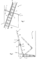
- Figure 1 shows a conductor 1 in an upright position in one Shaft pit 7. In this position, the ladder 1 is safe walkable. The ladder 1 rests on the shaft bottom 7.3 and leaning against a door sill of a doorway above the Shaft pit 7 on.
- the conductor 1 is arranged in two parallel and interconnected via a plurality of ladder rungs 4 Ladder rails 2, 3 formed.
- the ladder bars 2, 3 run parallel to a longitudinal axis 1.1 of the ladder 1.
- a securing element 5 arranged, as shown in more detail in Figure 8 is.
- the securing element 5 engages in a recess 7.1 in the threshold, which as a guide rail for not shown elevator doors used.
- Figure 2 shows a hinged ladder 1.
- the two ladder bars 2, 3 each consist of two partial beams 2a, 2b, 3a, 3b, which in each case via a joint 2.1 with each other are connected.
- the joint 2.1 is parallel to one to the ladder rung 4 extending axis of rotation 9 rotatable.
- the angle ⁇ , the two partial beams 2a, 2b in the upright Include position is 180 °. Only in this upright position in which the conductor 1 on the fuse element 5 in the recess 7.1 at the threshold is hinged, locked the joint 2.1.
- the joint 2.1 can via a not shown traction means solved in the form of a tug for folding the ladder 1 become.
- the joint snaps into place 2.1 automatically in the described angular position of 180 °.
- the ladder spar 2 is on a bearing 1.2 on the shaft bottom 7.3 the shaft pit 7 attached and to a parallel to the ladder rung 4 extending pivot axis 1.3 in the camp 1.2 pivotally mounted.
- the ladder 1 pivots outgoing from the upright position when folding and accordingly when unfolding about the pivot axis 1.3.
- Figures 3 to 7 show the fuse element 5, respectively two holes for attaching to the ladder 1 in Top view and in profile cross section.
- the fuse element 5 also has a recess 5.3 for hanging the Head 1 in the pit 7 on.
- the securing element 5 according to FIG. 3 is made of an angle profile formed, consisting essentially of two together adjacent sides 5a, 5b exists. Pages 5a, 5b include an angle ⁇ of 110 °.
- the fold 5.1 is provided, with the securing element 5 in the recess 7.1 at the threshold is used.
- securing elements 5 is the fold 5.1 replaced by one or more pin 5.2.
- the Pins 5.2 are arranged centrally on the second side 5b.
- FIG 6 is a pivotable about an axis 8 fuse element 5 is shown.
- the second side 5b is pivotable mounted about the axis 8 on the first side 5a.
- the fuse element 5 can be hooked into the recess 7.1 pivot over a tug, not shown.
- the securing element 5 is via a fastening device 6 between the ladder struts 2, 3 are arranged.
- the fastening device 6 has a pair of rails 6.1, 6.2 on, from each of a rail 6.1, 6.2 at each a ladder stile 2, 3 is fixed.
- the rail 6.1, 6.2 is formed from a C-profile, in which the securing element 5 slidable in the direction of the longitudinal axis 1.1 and with the help of screws in the rails 6.1, 6.2 are determined, can be fixed.
- the rail pair 6.1, 6.2 has a length of up to 1400 mm, so that the securing element 5 as shown in Figure 10 in a range of about 1360 mm is adjustable.
- FIG. 9 The sectional view according to section A-A 'is shown in FIG. 9 shown.
- the conductor 1 is connected via a holder 7.4 the shaft pit 7 suspended for storage.
- the holder 7.4 is designed as a screw with the wall of the Shaft pit 7 is pegged.
- the fuse element 5 has the recess 5.3 (Fig. 3), over which the securing element 5 and thus the conductor 1 suspended from the screw 7.4 becomes. Through the recess 5.3, the conductor 1 can the holder 7.4 does not slip.
- An additional fuse of the conductor 1 is as in the figures 8 and 10 shown achieved via a traction means 7.2, which connects the holder 7.4 with the conductor 1.
- This Traction 7.2 serves as a backup that the conductor 1 not stolen from the pit 7 or not at one other than the intended for the ladder 1 place within the shaft pit 7 is stowed.
- the Ladder 1 which is placed on the shaft bottom 7.3 of raise the door opening with the aid of the traction device 7.2, to climb the shaft pit 7.
- the traction means is 7.2 near the door opening on the wall of the pit 7 attached.
- the pulling means 7.2 is used to to erect the ladder 1.
Landscapes
- Engineering & Computer Science (AREA)
- Mechanical Engineering (AREA)
- Architecture (AREA)
- Structural Engineering (AREA)
- Ladders (AREA)
Abstract
Description
- Figur 1
- eine perspektivische Darstellung einer Leiter in einer Schachtgrube;
- Figur 2
- eine perspektivische Darstellung einer klappbaren Leiter mit einem Lager auf der Schachtsohle der Schachtgrube in drei verschiedenen Positionen;
- Figur 3
- ein starres Sicherungselement mit einer Abkantung;
- Figur 4
- ein starres Sicherungselement mit zwei Zapfen;
- Figur 5
- ein starres Sicherungselement mit einem Zapfen;
- Figur 6
- ein klappbares Sicherungselement;
- Figur 7
- ein flexibles Sicherungselement;
- Figur 8
- einen Teil einer Leiter mit einem Sicherungselement in Draufsicht mit Schnittführung A-A';
- Figur 9
- die Schnittansicht A-A' gemäß Figur 8;
- Figur 10
- eine perspektivische Darstellung einer Leiter mit verschiebbarem Sicherungselement.
Claims (19)
- Leiter (1) für Schachtgruben (7) von Aufzügen mit mindestens einem ersten und einem zweiten Leiterholm (2, 3) und mindestens drei die beiden Leiterholme (2, 3) verbindenden Leitersprossen (4), wobei an der Leiter (1) ein Sicherungselement (5) vorgesehen ist, mit Hilfe dessen die Leiter (1) in einer aufrechten Position, in der die Leiter (1) begehbar ist, an der Schachtgrube (7) gegen Verkippen sicherbar ist,
dadurch gekennzeichnet, dass mindestens ein Leiterholm (2) über ein Lager (1.2) auf oder unmittelbar über der Schachtsohle (7.3) der Schachtgrube (7) befestigbar ist, wobei der Leiterholm (2) um eine parallel zu der Leitersprosse (4) verlaufende Schwenkachse (1.3) im Lager (1.2) schwenkbar ist. - Leiter (1) für Schachtgruben (7) von Aufzügen mit mindestens einem ersten und einem zweiten Leiterholm (2, 3) und mindestens drei die beiden Leiterholme (2, 3) verbindenden Leitersprossen (4), wobei an der Leiter (1) ein Sicherungselement (5) vorgesehen ist, mit Hilfe dessen die Leiter (1) in einer aufrechten Position, in der die Leiter (1) begehbar ist, an der Schachtgrube (7) gegen Verkippen sicherbar ist,
dadurch gekennzeichnet, dassa) das Sicherungselement (5) parallel zu einer Längsachse (1.1) der Leiter (1) verschiebbar an mindestens einem Leiterholm (2) gelagert ist undb) das Sicherungselement (5) über eine Befestigungsvorrichtung (6) in mindestens zwei Positionen festsetzbar ist,c) die Befestigungsvorrichtung (6) eine erste und eine zweite jeweils parallel zu dem Leiterholm (2, 3) befestigte Schiene (6.1, 6.2) aufweist undd) das Sicherungselement (5) über das Schienenpaar (6.1, 6.2) justierbar und stufenlos festsetzbar ist. - Vorrichtung nach Anspruch 1 oder 2,
dadurch gekennzeichnet , dass das Sicherungselement (5) eine Abkantung (5.1) oder mindestens einen Zapfen (5.2) aufweist, wobei die Abkantung (5.1) oder der Zapfen (5.2) in eine zumindest nach oben offene Vertiefung (7.1) im Randbereich der Schachtgrube (7) einsteck- und/oder einhängbar ist. - Vorrichtung nach 1 oder 2,
dadurch gekennzeichnet, dass das Sicherungselement (5) als Winkelprofil mit im Wesentlichen zwei ebenen, aneinander anschließenden Seiten (5a, 5b) ausgebildet ist, die erste Seite (5a) parallel zur Längsachse (1.1) angeordnet ist und mit der zweiten Seite (5b) einen Winkel (α) zwischen 75° und 145°, im Besonderen zwischen 95° und 125° einschließt. - Vorrichtung nach Anspruch 3 oder 4,
dadurch gekennzeichnet, dass die Abkantung (5.1) oder der Zapfen (5.2) im Wesentlichen rechtwinklig zur zweiten Seite (5b) an der zweiten Seite (5b) angeordnet ist. - Vorrichtung nach einem der vorhergehenden Ansprüche,
dadurch gekennzeichnet, dass das Sicherungselement (5) oder die zweite Seite (5b) des Sicherungselements (5) schwenkbar um eine parallel zu der Leitersprosse (4) verlaufende Achse (8) gelagert ist. - Vorrichtung nach einem der Ansprüche 4 bis 6,
dadurch gekennzeichnet, dass die zweite Seite (5b) verschiebbar zur ersten Seite (5a) an der ersten Seite (5a) gelagert ist. - Vorrichtung nach einem der Ansprüche 2 bis 7,
dadurch gekennzeichnet, dass das Schienenpaar (6.1, 6.2) an den Leiterholmen (2, 3) oder zwischen den Leiterholmen (2, 3) angeordnet ist. - Vorrichtung nach einem der vorhergehenden Ansprüche,
dadurch gekennzeichnet, dass die Leiterholme (2, 3) parallel oder in einem Winkel bis zu 25° zueinander angeordnet sind. - Vorrichtung nach Anspruch 9,
dadurch gekennzeichnet, dass das Sicherungselement (5) zumindest zwei Langlöcher aufweist, über welche das Sicherungselement (5) an den Schienen (6.1, 6.2) festsetzbar ist, wobei die Langlöcher rechtwinklig zur Längsachse (1.1) ausgerichtet sind. - Vorrichtung nach einem der Ansprüche 1, 3 bis 10,
dadurch gekennzeichnet, dass das Sicherungselement (5) mindestens eine Aussparung (5.3) zum Aufhängen der Leiter (1) in der Schachtgrube (7) aufweist. - Vorrichtung nach Anspruch 11,
dadurch gekennzeichnet, dass die Aussparung (5.3) einer an der Schachtgrube (7) befestigten Halterung (7.4) zugeordnet ist und die Halterung (7.4) über ein Zugmittel (7.2) zumindest mittelbar mit der Leiter (1) verbindbar ist. - Vorrichtung nach einem der Ansprüche 1, 3 bis 10,
dadurch gekennzeichnet, dass die beiden Leiterholme (2, 3) jeweils aus zwei Teilholmen (2a, 2b, 3a, 3b) bestehen, die über jeweils ein Gelenk (2.1) miteinander verbunden sind, wobei das Gelenk (2.1) um eine parallel zu der Leitersprosse (4) verlaufende Drehachse (9) drehbar ist. - Vorrichtung nach Anspruch 13,
dadurch gekennzeichnet, dass mindestens ein Gelenk (2.1) in einer definierten Winkelstellung der beiden Teilholme (2a, 2b) verrastet. - Vorrichtung nach Anspruch 14,
dadurch gekennzeichnet, dass das Gelenk (2.1) verrastet, wenn die beiden Teilholme (2a, 2b) einen Winkel (β) zwischen 170° und 190° einschließen. - Vorrichtung nach einem der Ansprüche 13 bis 15,
dadurch gekennzeichnet, dass das verrastete Gelenk (2.1) über einen am Gelenk (2.1) angeordneten Hebel gelöst werden kann und der Hebel mit Hilfe eines Zugmittels bedienbar ist. - Vorrichtung nach einem der Ansprüche 1, 3 bis 10, 13 bis 16,
dadurch gekennzeichnet, dass der Leiterholm (2) mindestens in einer radialen Richtung zur Schwenkachse (1.3) verschiebbar im Lager (1.2) gelagert ist. - Vorrichtung nach einem der vorhergehenden Ansprüche,
dadurch gekennzeichnet, dass mindestens ein Leiterholm (2) eine Verlängerung aufweist, wobei die Verlängerung in Richtung der Längsachse (1.1) verschiebbar am Leiterholm (2) gelagert ist und einen Handlauf bildet. - Vorrichtung nach den Ansprüchen 1 und 2.
Applications Claiming Priority (2)
| Application Number | Priority Date | Filing Date | Title |
|---|---|---|---|
| DE200410030897 DE102004030897A1 (de) | 2004-06-25 | 2004-06-25 | Leiter |
| DE102004030897 | 2004-06-25 |
Publications (2)
| Publication Number | Publication Date |
|---|---|
| EP1609943A1 true EP1609943A1 (de) | 2005-12-28 |
| EP1609943B1 EP1609943B1 (de) | 2014-10-15 |
Family
ID=35045321
Family Applications (1)
| Application Number | Title | Priority Date | Filing Date |
|---|---|---|---|
| EP20050013658 Expired - Lifetime EP1609943B1 (de) | 2004-06-25 | 2005-06-24 | Leiter |
Country Status (2)
| Country | Link |
|---|---|
| EP (1) | EP1609943B1 (de) |
| DE (1) | DE102004030897A1 (de) |
Cited By (4)
| Publication number | Priority date | Publication date | Assignee | Title |
|---|---|---|---|---|
| DE202007004541U1 (de) | 2007-03-28 | 2008-08-07 | W+W Aufzugkomponenten Gmbh U. Co. Kg | Stufen-Anlegeleiter zum Abstieg in Aufzugschachtgruben |
| DE102007014826B3 (de) * | 2007-03-28 | 2008-12-18 | W+W Aufzugkomponenten Gmbh U. Co. Kg | Zusammenklappbare Stufen-Anlegeleiter zum Abstieg in Aufzugschachtgruben |
| CN105971491A (zh) * | 2016-06-24 | 2016-09-28 | 浙江荣华家具有限公司 | 折叠宿舍梯 |
| EP3130743A1 (de) | 2015-08-12 | 2017-02-15 | Kone Corporation | Grubenleiter mit sicherheitsvorrichtung |
Citations (8)
| Publication number | Priority date | Publication date | Assignee | Title |
|---|---|---|---|---|
| US4207886A (en) * | 1979-04-13 | 1980-06-17 | Sorenson Virgil H | Ladder adjusting and stabilizing apparatus |
| US4483416A (en) * | 1983-12-08 | 1984-11-20 | Garcia Eduardo L | Height adjustable roof engaging attachment for ladders |
| GB2142076A (en) * | 1983-06-22 | 1985-01-09 | David John Roberts | Ladder support |
| US5279389A (en) * | 1992-06-08 | 1994-01-18 | Crockett Robert A | Ladder support for flat-roofed building |
| FR2694783A1 (fr) | 1992-08-14 | 1994-02-18 | Quille Entreprise | Dispositif de sécurité pour éviter le renversement d'une échelle. |
| FR2725971A1 (fr) * | 1994-10-06 | 1996-04-26 | Hognon Sa | Dispositif d'acces au fonds de cuvette des ascenseurs |
| DE19825902A1 (de) * | 1998-06-10 | 1999-12-16 | Wilhelm Bader | Vorrichtung zum Sichern einer Leiter gegen Verrutschen auf dem Fußboden |
| US6138794A (en) * | 1997-09-16 | 2000-10-31 | Transafety Inc. | Portable self-adjusting ladder |
Family Cites Families (5)
| Publication number | Priority date | Publication date | Assignee | Title |
|---|---|---|---|---|
| DE2059544C3 (de) * | 1970-12-03 | 1974-06-27 | Albert 7445 Bempflingen Hess | Faltleiter bzw. zusammenfaltbare Stange |
| DE7616270U1 (de) * | 1976-05-21 | 1976-09-30 | Peter Lancier Kg Maschinenbau-Hafenhuette, 4400 Muenster | Schwenkbare kabelschachtleiter |
| DE3040663A1 (de) * | 1980-10-29 | 1982-05-27 | Brennenstuhl, Hugo, 7400 Tübingen | Mehrzweckleiter |
| DE9218570U1 (de) * | 1991-10-15 | 1994-09-08 | M.S.U. Matériel de Sécurité Urbain (S.A.), Pulversheim | Auszugsleiter |
| DE19859614B4 (de) * | 1998-12-23 | 2009-08-13 | B+N Bergbautechnik Handels Gmbh | Einhängeleiter für mobile Einstieghilfe |
-
2004
- 2004-06-25 DE DE200410030897 patent/DE102004030897A1/de not_active Withdrawn
-
2005
- 2005-06-24 EP EP20050013658 patent/EP1609943B1/de not_active Expired - Lifetime
Patent Citations (8)
| Publication number | Priority date | Publication date | Assignee | Title |
|---|---|---|---|---|
| US4207886A (en) * | 1979-04-13 | 1980-06-17 | Sorenson Virgil H | Ladder adjusting and stabilizing apparatus |
| GB2142076A (en) * | 1983-06-22 | 1985-01-09 | David John Roberts | Ladder support |
| US4483416A (en) * | 1983-12-08 | 1984-11-20 | Garcia Eduardo L | Height adjustable roof engaging attachment for ladders |
| US5279389A (en) * | 1992-06-08 | 1994-01-18 | Crockett Robert A | Ladder support for flat-roofed building |
| FR2694783A1 (fr) | 1992-08-14 | 1994-02-18 | Quille Entreprise | Dispositif de sécurité pour éviter le renversement d'une échelle. |
| FR2725971A1 (fr) * | 1994-10-06 | 1996-04-26 | Hognon Sa | Dispositif d'acces au fonds de cuvette des ascenseurs |
| US6138794A (en) * | 1997-09-16 | 2000-10-31 | Transafety Inc. | Portable self-adjusting ladder |
| DE19825902A1 (de) * | 1998-06-10 | 1999-12-16 | Wilhelm Bader | Vorrichtung zum Sichern einer Leiter gegen Verrutschen auf dem Fußboden |
Cited By (7)
| Publication number | Priority date | Publication date | Assignee | Title |
|---|---|---|---|---|
| DE202007004541U1 (de) | 2007-03-28 | 2008-08-07 | W+W Aufzugkomponenten Gmbh U. Co. Kg | Stufen-Anlegeleiter zum Abstieg in Aufzugschachtgruben |
| DE102007014826B3 (de) * | 2007-03-28 | 2008-12-18 | W+W Aufzugkomponenten Gmbh U. Co. Kg | Zusammenklappbare Stufen-Anlegeleiter zum Abstieg in Aufzugschachtgruben |
| EP3130743A1 (de) | 2015-08-12 | 2017-02-15 | Kone Corporation | Grubenleiter mit sicherheitsvorrichtung |
| CN106437479A (zh) * | 2015-08-12 | 2017-02-22 | 通力股份公司 | 具有安全装置的井坑梯子 |
| US9976347B2 (en) | 2015-08-12 | 2018-05-22 | Kone Corporation | Pit ladder with safety device |
| CN106437479B (zh) * | 2015-08-12 | 2020-10-13 | 通力股份公司 | 具有安全装置的井坑梯子 |
| CN105971491A (zh) * | 2016-06-24 | 2016-09-28 | 浙江荣华家具有限公司 | 折叠宿舍梯 |
Also Published As
| Publication number | Publication date |
|---|---|
| EP1609943B1 (de) | 2014-10-15 |
| DE102004030897A1 (de) | 2006-11-23 |
Similar Documents
| Publication | Publication Date | Title |
|---|---|---|
| DE3310317C2 (de) | Laufkonsole mit einer Tür | |
| WO2000009850A1 (de) | Rutschsicherung für leitern | |
| DE102014014263A1 (de) | Leiter mit variabler Holmverlängerung | |
| DE102011106083A1 (de) | Ständer für PV-Module | |
| DE102014222249A1 (de) | Verfahren und Vorrichtung zur Montage eines Gerüstturms | |
| DE60317171T2 (de) | Einstellbares modulares Sicherheitssystem für Gerüste | |
| EP0733766A2 (de) | Aufhängevorrichtung für ein verschiebbares Element | |
| EP1609943B1 (de) | Leiter | |
| DE202008012478U1 (de) | Längenveränderliche Arbeitsbühne, insbesondere für Kletterrüstungen | |
| DE3505917C2 (de) | ||
| DE102007014826B3 (de) | Zusammenklappbare Stufen-Anlegeleiter zum Abstieg in Aufzugschachtgruben | |
| DE3733702A1 (de) | Zusammenfaltbare steigleiter | |
| DE19835684C2 (de) | Verfahrbare Türflügelanordnung | |
| EP3485127B1 (de) | Einsatzrampe | |
| DE10238013B3 (de) | Podest-Mehrzweckleiter für Treppenhäuser | |
| DE8425323U1 (de) | Haltevorrichtung für eine Plattform | |
| DE3622830A1 (de) | Vorrichtung fuer sichere luft | |
| EP4528067B1 (de) | Leiter mit klappbaren sprossen | |
| EP3737812B1 (de) | Vorrichtung zum offenhalten geöffneter fenster | |
| DE102022122562A1 (de) | Dachfenstereinrichtung, Dachfensteranordnung und Verfahren zur Montage einer solchen Dachfenstereinrichtung in einer Dachfensteröffnung | |
| EP3431700A1 (de) | Kippsicherung für leitern | |
| DE202007004541U1 (de) | Stufen-Anlegeleiter zum Abstieg in Aufzugschachtgruben | |
| EP1283129A1 (de) | Klapptreppe für Wohnwagen oder Wohnmobile | |
| DE102023112162A1 (de) | Leiter | |
| DE2140476C3 (de) | Aus zwei Einzelleitern bestehende und in verstellbarer Höhenlage spreizbare Stehleiter |
Legal Events
| Date | Code | Title | Description |
|---|---|---|---|
| PUAI | Public reference made under article 153(3) epc to a published international application that has entered the european phase |
Free format text: ORIGINAL CODE: 0009012 |
|
| AK | Designated contracting states |
Kind code of ref document: A1 Designated state(s): AT BE BG CH CY CZ DE DK EE ES FI FR GB GR HU IE IS IT LI LT LU MC NL PL PT RO SE SI SK TR |
|
| AX | Request for extension of the european patent |
Extension state: AL BA HR LV MK YU |
|
| 17P | Request for examination filed |
Effective date: 20060621 |
|
| AKX | Designation fees paid |
Designated state(s): AT BE BG CH CY CZ DE DK EE ES FI FR GB GR HU IE IS IT LI LT LU MC NL PL PT RO SE SI SK TR |
|
| 17Q | First examination report despatched |
Effective date: 20080314 |
|
| GRAP | Despatch of communication of intention to grant a patent |
Free format text: ORIGINAL CODE: EPIDOSNIGR1 |
|
| INTG | Intention to grant announced |
Effective date: 20140626 |
|
| GRAS | Grant fee paid |
Free format text: ORIGINAL CODE: EPIDOSNIGR3 |
|
| GRAA | (expected) grant |
Free format text: ORIGINAL CODE: 0009210 |
|
| AK | Designated contracting states |
Kind code of ref document: B1 Designated state(s): AT BE BG CH CY CZ DE DK EE ES FI FR GB GR HU IE IS IT LI LT LU MC NL PL PT RO SE SI SK TR |
|
| REG | Reference to a national code |
Ref country code: GB Ref legal event code: FG4D Free format text: NOT ENGLISH Ref country code: CH Ref legal event code: EP |
|
| REG | Reference to a national code |
Ref country code: IE Ref legal event code: FG4D Free format text: LANGUAGE OF EP DOCUMENT: GERMAN |
|
| REG | Reference to a national code |
Ref country code: AT Ref legal event code: REF Ref document number: 691787 Country of ref document: AT Kind code of ref document: T Effective date: 20141115 |
|
| REG | Reference to a national code |
Ref country code: DE Ref legal event code: R096 Ref document number: 502005014554 Country of ref document: DE Effective date: 20141127 |
|
| REG | Reference to a national code |
Ref country code: NL Ref legal event code: VDEP Effective date: 20141015 |
|
| REG | Reference to a national code |
Ref country code: LT Ref legal event code: MG4D |
|
| PG25 | Lapsed in a contracting state [announced via postgrant information from national office to epo] |
Ref country code: NL Free format text: LAPSE BECAUSE OF FAILURE TO SUBMIT A TRANSLATION OF THE DESCRIPTION OR TO PAY THE FEE WITHIN THE PRESCRIBED TIME-LIMIT Effective date: 20141015 |
|
| PG25 | Lapsed in a contracting state [announced via postgrant information from national office to epo] |
Ref country code: IS Free format text: LAPSE BECAUSE OF FAILURE TO SUBMIT A TRANSLATION OF THE DESCRIPTION OR TO PAY THE FEE WITHIN THE PRESCRIBED TIME-LIMIT Effective date: 20150215 Ref country code: FI Free format text: LAPSE BECAUSE OF FAILURE TO SUBMIT A TRANSLATION OF THE DESCRIPTION OR TO PAY THE FEE WITHIN THE PRESCRIBED TIME-LIMIT Effective date: 20141015 Ref country code: LT Free format text: LAPSE BECAUSE OF FAILURE TO SUBMIT A TRANSLATION OF THE DESCRIPTION OR TO PAY THE FEE WITHIN THE PRESCRIBED TIME-LIMIT Effective date: 20141015 Ref country code: ES Free format text: LAPSE BECAUSE OF FAILURE TO SUBMIT A TRANSLATION OF THE DESCRIPTION OR TO PAY THE FEE WITHIN THE PRESCRIBED TIME-LIMIT Effective date: 20141015 Ref country code: PT Free format text: LAPSE BECAUSE OF FAILURE TO SUBMIT A TRANSLATION OF THE DESCRIPTION OR TO PAY THE FEE WITHIN THE PRESCRIBED TIME-LIMIT Effective date: 20150216 |
|
| PG25 | Lapsed in a contracting state [announced via postgrant information from national office to epo] |
Ref country code: PL Free format text: LAPSE BECAUSE OF FAILURE TO SUBMIT A TRANSLATION OF THE DESCRIPTION OR TO PAY THE FEE WITHIN THE PRESCRIBED TIME-LIMIT Effective date: 20141015 Ref country code: GR Free format text: LAPSE BECAUSE OF FAILURE TO SUBMIT A TRANSLATION OF THE DESCRIPTION OR TO PAY THE FEE WITHIN THE PRESCRIBED TIME-LIMIT Effective date: 20150116 Ref country code: SE Free format text: LAPSE BECAUSE OF FAILURE TO SUBMIT A TRANSLATION OF THE DESCRIPTION OR TO PAY THE FEE WITHIN THE PRESCRIBED TIME-LIMIT Effective date: 20141015 Ref country code: CY Free format text: LAPSE BECAUSE OF FAILURE TO SUBMIT A TRANSLATION OF THE DESCRIPTION OR TO PAY THE FEE WITHIN THE PRESCRIBED TIME-LIMIT Effective date: 20141015 |
|
| REG | Reference to a national code |
Ref country code: DE Ref legal event code: R097 Ref document number: 502005014554 Country of ref document: DE |
|
| PG25 | Lapsed in a contracting state [announced via postgrant information from national office to epo] |
Ref country code: EE Free format text: LAPSE BECAUSE OF FAILURE TO SUBMIT A TRANSLATION OF THE DESCRIPTION OR TO PAY THE FEE WITHIN THE PRESCRIBED TIME-LIMIT Effective date: 20141015 Ref country code: CZ Free format text: LAPSE BECAUSE OF FAILURE TO SUBMIT A TRANSLATION OF THE DESCRIPTION OR TO PAY THE FEE WITHIN THE PRESCRIBED TIME-LIMIT Effective date: 20141015 Ref country code: DK Free format text: LAPSE BECAUSE OF FAILURE TO SUBMIT A TRANSLATION OF THE DESCRIPTION OR TO PAY THE FEE WITHIN THE PRESCRIBED TIME-LIMIT Effective date: 20141015 Ref country code: RO Free format text: LAPSE BECAUSE OF FAILURE TO SUBMIT A TRANSLATION OF THE DESCRIPTION OR TO PAY THE FEE WITHIN THE PRESCRIBED TIME-LIMIT Effective date: 20141015 Ref country code: SK Free format text: LAPSE BECAUSE OF FAILURE TO SUBMIT A TRANSLATION OF THE DESCRIPTION OR TO PAY THE FEE WITHIN THE PRESCRIBED TIME-LIMIT Effective date: 20141015 |
|
| PLBE | No opposition filed within time limit |
Free format text: ORIGINAL CODE: 0009261 |
|
| STAA | Information on the status of an ep patent application or granted ep patent |
Free format text: STATUS: NO OPPOSITION FILED WITHIN TIME LIMIT |
|
| PG25 | Lapsed in a contracting state [announced via postgrant information from national office to epo] |
Ref country code: IT Free format text: LAPSE BECAUSE OF FAILURE TO SUBMIT A TRANSLATION OF THE DESCRIPTION OR TO PAY THE FEE WITHIN THE PRESCRIBED TIME-LIMIT Effective date: 20141015 |
|
| 26N | No opposition filed |
Effective date: 20150716 |
|
| PG25 | Lapsed in a contracting state [announced via postgrant information from national office to epo] |
Ref country code: MC Free format text: LAPSE BECAUSE OF FAILURE TO SUBMIT A TRANSLATION OF THE DESCRIPTION OR TO PAY THE FEE WITHIN THE PRESCRIBED TIME-LIMIT Effective date: 20141015 |
|
| REG | Reference to a national code |
Ref country code: CH Ref legal event code: PL |
|
| PG25 | Lapsed in a contracting state [announced via postgrant information from national office to epo] |
Ref country code: SI Free format text: LAPSE BECAUSE OF FAILURE TO SUBMIT A TRANSLATION OF THE DESCRIPTION OR TO PAY THE FEE WITHIN THE PRESCRIBED TIME-LIMIT Effective date: 20141015 Ref country code: LU Free format text: LAPSE BECAUSE OF FAILURE TO SUBMIT A TRANSLATION OF THE DESCRIPTION OR TO PAY THE FEE WITHIN THE PRESCRIBED TIME-LIMIT Effective date: 20150624 |
|
| REG | Reference to a national code |
Ref country code: IE Ref legal event code: MM4A |
|
| REG | Reference to a national code |
Ref country code: FR Ref legal event code: ST Effective date: 20160229 |
|
| PG25 | Lapsed in a contracting state [announced via postgrant information from national office to epo] |
Ref country code: LI Free format text: LAPSE BECAUSE OF NON-PAYMENT OF DUE FEES Effective date: 20150630 Ref country code: IE Free format text: LAPSE BECAUSE OF NON-PAYMENT OF DUE FEES Effective date: 20150624 Ref country code: CH Free format text: LAPSE BECAUSE OF NON-PAYMENT OF DUE FEES Effective date: 20150630 |
|
| PG25 | Lapsed in a contracting state [announced via postgrant information from national office to epo] |
Ref country code: FR Free format text: LAPSE BECAUSE OF NON-PAYMENT OF DUE FEES Effective date: 20150630 |
|
| REG | Reference to a national code |
Ref country code: AT Ref legal event code: MM01 Ref document number: 691787 Country of ref document: AT Kind code of ref document: T Effective date: 20150624 |
|
| PG25 | Lapsed in a contracting state [announced via postgrant information from national office to epo] |
Ref country code: AT Free format text: LAPSE BECAUSE OF NON-PAYMENT OF DUE FEES Effective date: 20150624 |
|
| PG25 | Lapsed in a contracting state [announced via postgrant information from national office to epo] |
Ref country code: HU Free format text: LAPSE BECAUSE OF FAILURE TO SUBMIT A TRANSLATION OF THE DESCRIPTION OR TO PAY THE FEE WITHIN THE PRESCRIBED TIME-LIMIT; INVALID AB INITIO Effective date: 20050624 Ref country code: BG Free format text: LAPSE BECAUSE OF FAILURE TO SUBMIT A TRANSLATION OF THE DESCRIPTION OR TO PAY THE FEE WITHIN THE PRESCRIBED TIME-LIMIT Effective date: 20141015 |
|
| PG25 | Lapsed in a contracting state [announced via postgrant information from national office to epo] |
Ref country code: BE Free format text: LAPSE BECAUSE OF NON-PAYMENT OF DUE FEES Effective date: 20150630 |
|
| PG25 | Lapsed in a contracting state [announced via postgrant information from national office to epo] |
Ref country code: TR Free format text: LAPSE BECAUSE OF FAILURE TO SUBMIT A TRANSLATION OF THE DESCRIPTION OR TO PAY THE FEE WITHIN THE PRESCRIBED TIME-LIMIT Effective date: 20141015 |
|
| PGFP | Annual fee paid to national office [announced via postgrant information from national office to epo] |
Ref country code: DE Payment date: 20230620 Year of fee payment: 19 |
|
| PGFP | Annual fee paid to national office [announced via postgrant information from national office to epo] |
Ref country code: GB Payment date: 20230620 Year of fee payment: 19 |
|
| P01 | Opt-out of the competence of the unified patent court (upc) registered |
Effective date: 20240220 |
|
| REG | Reference to a national code |
Ref country code: DE Ref legal event code: R119 Ref document number: 502005014554 Country of ref document: DE |
|
| GBPC | Gb: european patent ceased through non-payment of renewal fee |
Effective date: 20240624 |
|
| PG25 | Lapsed in a contracting state [announced via postgrant information from national office to epo] |
Ref country code: DE Free format text: LAPSE BECAUSE OF NON-PAYMENT OF DUE FEES Effective date: 20250101 |
|
| PG25 | Lapsed in a contracting state [announced via postgrant information from national office to epo] |
Ref country code: GB Free format text: LAPSE BECAUSE OF NON-PAYMENT OF DUE FEES Effective date: 20240624 |