EP1608165B1 - AUFZEICHNUNGSMEDIUM, WIEDERGABEVORRICHTUNG, AUFZEICHNUNGSVERFAHREN, PROGRAMM UND WIEDERGABEVERFAHREN für einen Grafikdatenstrom zur Definition von interaktiven Schaltflächen. - Google Patents
AUFZEICHNUNGSMEDIUM, WIEDERGABEVORRICHTUNG, AUFZEICHNUNGSVERFAHREN, PROGRAMM UND WIEDERGABEVERFAHREN für einen Grafikdatenstrom zur Definition von interaktiven Schaltflächen. Download PDFInfo
- Publication number
- EP1608165B1 EP1608165B1 EP04706788A EP04706788A EP1608165B1 EP 1608165 B1 EP1608165 B1 EP 1608165B1 EP 04706788 A EP04706788 A EP 04706788A EP 04706788 A EP04706788 A EP 04706788A EP 1608165 B1 EP1608165 B1 EP 1608165B1
- Authority
- EP
- European Patent Office
- Prior art keywords
- button
- graphics
- ics
- stream
- ods
- Prior art date
- Legal status (The legal status is an assumption and is not a legal conclusion. Google has not performed a legal analysis and makes no representation as to the accuracy of the status listed.)
- Expired - Lifetime
Links
- 230000002452 interceptive effect Effects 0.000 title claims description 103
- 238000000034 method Methods 0.000 title claims description 18
- PWPJGUXAGUPAHP-UHFFFAOYSA-N lufenuron Chemical compound C1=C(Cl)C(OC(F)(F)C(C(F)(F)F)F)=CC(Cl)=C1NC(=O)NC(=O)C1=C(F)C=CC=C1F PWPJGUXAGUPAHP-UHFFFAOYSA-N 0.000 title 1
- 238000012545 processing Methods 0.000 claims description 69
- 230000008859 change Effects 0.000 claims description 18
- 230000004044 response Effects 0.000 claims description 18
- 239000008186 active pharmaceutical agent Substances 0.000 description 75
- 239000000872 buffer Substances 0.000 description 62
- 238000001094 photothermal spectroscopy Methods 0.000 description 58
- 238000009877 rendering Methods 0.000 description 34
- 230000015654 memory Effects 0.000 description 31
- 230000007704 transition Effects 0.000 description 18
- 238000002156 mixing Methods 0.000 description 17
- 239000000203 mixture Substances 0.000 description 17
- 230000036316 preload Effects 0.000 description 16
- 230000006870 function Effects 0.000 description 13
- 230000001360 synchronised effect Effects 0.000 description 13
- 239000012634 fragment Substances 0.000 description 11
- 238000012360 testing method Methods 0.000 description 11
- 101000608720 Helianthus annuus 10 kDa late embryogenesis abundant protein Proteins 0.000 description 10
- 238000004519 manufacturing process Methods 0.000 description 10
- 238000001824 photoionisation detection Methods 0.000 description 10
- 238000012546 transfer Methods 0.000 description 9
- 238000012795 verification Methods 0.000 description 8
- 230000002093 peripheral effect Effects 0.000 description 7
- 238000006243 chemical reaction Methods 0.000 description 4
- 239000003086 colorant Substances 0.000 description 4
- 239000002131 composite material Substances 0.000 description 4
- 230000006835 compression Effects 0.000 description 4
- 238000007906 compression Methods 0.000 description 4
- 230000000694 effects Effects 0.000 description 4
- 230000004048 modification Effects 0.000 description 4
- 238000012986 modification Methods 0.000 description 4
- 239000000725 suspension Substances 0.000 description 4
- 102100037812 Medium-wave-sensitive opsin 1 Human genes 0.000 description 3
- 230000009471 action Effects 0.000 description 3
- 230000004913 activation Effects 0.000 description 3
- 230000006872 improvement Effects 0.000 description 3
- 239000000463 material Substances 0.000 description 3
- 238000003825 pressing Methods 0.000 description 3
- 230000000153 supplemental effect Effects 0.000 description 3
- 238000012937 correction Methods 0.000 description 2
- 230000006837 decompression Effects 0.000 description 2
- 238000009826 distribution Methods 0.000 description 2
- 238000001119 image correlation spectroscopy Methods 0.000 description 2
- 230000003287 optical effect Effects 0.000 description 2
- 230000008569 process Effects 0.000 description 2
- 230000003068 static effect Effects 0.000 description 2
- 101100395863 Caenorhabditis elegans hst-2 gene Proteins 0.000 description 1
- 102100034013 Gamma-glutamyl phosphate reductase Human genes 0.000 description 1
- 101150101014 HST1 gene Proteins 0.000 description 1
- 238000010420 art technique Methods 0.000 description 1
- 230000003139 buffering effect Effects 0.000 description 1
- 238000004891 communication Methods 0.000 description 1
- 238000010276 construction Methods 0.000 description 1
- 230000001934 delay Effects 0.000 description 1
- 101150069022 dss-1 gene Proteins 0.000 description 1
- 239000000284 extract Substances 0.000 description 1
- 230000008921 facial expression Effects 0.000 description 1
- 238000001914 filtration Methods 0.000 description 1
- 230000010365 information processing Effects 0.000 description 1
- 230000010354 integration Effects 0.000 description 1
- 229920000117 poly(dioxanone) Polymers 0.000 description 1
- 230000009467 reduction Effects 0.000 description 1
- 230000002441 reversible effect Effects 0.000 description 1
- 238000005070 sampling Methods 0.000 description 1
- 239000004065 semiconductor Substances 0.000 description 1
- 239000000758 substrate Substances 0.000 description 1
- 230000001960 triggered effect Effects 0.000 description 1
- 238000010200 validation analysis Methods 0.000 description 1
Images


Classifications
-
- G—PHYSICS
- G11—INFORMATION STORAGE
- G11B—INFORMATION STORAGE BASED ON RELATIVE MOVEMENT BETWEEN RECORD CARRIER AND TRANSDUCER
- G11B27/00—Editing; Indexing; Addressing; Timing or synchronising; Monitoring; Measuring tape travel
- G11B27/10—Indexing; Addressing; Timing or synchronising; Measuring tape travel
- G11B27/34—Indicating arrangements
-
- G—PHYSICS
- G11—INFORMATION STORAGE
- G11B—INFORMATION STORAGE BASED ON RELATIVE MOVEMENT BETWEEN RECORD CARRIER AND TRANSDUCER
- G11B20/00—Signal processing not specific to the method of recording or reproducing; Circuits therefor
- G11B20/10—Digital recording or reproducing
-
- G—PHYSICS
- G11—INFORMATION STORAGE
- G11B—INFORMATION STORAGE BASED ON RELATIVE MOVEMENT BETWEEN RECORD CARRIER AND TRANSDUCER
- G11B20/00—Signal processing not specific to the method of recording or reproducing; Circuits therefor
- G11B20/10—Digital recording or reproducing
- G11B20/12—Formatting, e.g. arrangement of data block or words on the record carriers
-
- G—PHYSICS
- G11—INFORMATION STORAGE
- G11B—INFORMATION STORAGE BASED ON RELATIVE MOVEMENT BETWEEN RECORD CARRIER AND TRANSDUCER
- G11B27/00—Editing; Indexing; Addressing; Timing or synchronising; Monitoring; Measuring tape travel
-
- G—PHYSICS
- G11—INFORMATION STORAGE
- G11B—INFORMATION STORAGE BASED ON RELATIVE MOVEMENT BETWEEN RECORD CARRIER AND TRANSDUCER
- G11B27/00—Editing; Indexing; Addressing; Timing or synchronising; Monitoring; Measuring tape travel
- G11B27/02—Editing, e.g. varying the order of information signals recorded on, or reproduced from, record carriers
- G11B27/031—Electronic editing of digitised analogue information signals, e.g. audio or video signals
- G11B27/034—Electronic editing of digitised analogue information signals, e.g. audio or video signals on discs
-
- G—PHYSICS
- G11—INFORMATION STORAGE
- G11B—INFORMATION STORAGE BASED ON RELATIVE MOVEMENT BETWEEN RECORD CARRIER AND TRANSDUCER
- G11B27/00—Editing; Indexing; Addressing; Timing or synchronising; Monitoring; Measuring tape travel
- G11B27/10—Indexing; Addressing; Timing or synchronising; Measuring tape travel
- G11B27/102—Programmed access in sequence to addressed parts of tracks of operating record carriers
- G11B27/105—Programmed access in sequence to addressed parts of tracks of operating record carriers of operating discs
-
- G—PHYSICS
- G11—INFORMATION STORAGE
- G11B—INFORMATION STORAGE BASED ON RELATIVE MOVEMENT BETWEEN RECORD CARRIER AND TRANSDUCER
- G11B27/00—Editing; Indexing; Addressing; Timing or synchronising; Monitoring; Measuring tape travel
- G11B27/10—Indexing; Addressing; Timing or synchronising; Measuring tape travel
- G11B27/19—Indexing; Addressing; Timing or synchronising; Measuring tape travel by using information detectable on the record carrier
- G11B27/28—Indexing; Addressing; Timing or synchronising; Measuring tape travel by using information detectable on the record carrier by using information signals recorded by the same method as the main recording
- G11B27/30—Indexing; Addressing; Timing or synchronising; Measuring tape travel by using information detectable on the record carrier by using information signals recorded by the same method as the main recording on the same track as the main recording
- G11B27/3027—Indexing; Addressing; Timing or synchronising; Measuring tape travel by using information detectable on the record carrier by using information signals recorded by the same method as the main recording on the same track as the main recording used signal is digitally coded
- G11B27/3036—Time code signal
-
- H—ELECTRICITY
- H04—ELECTRIC COMMUNICATION TECHNIQUE
- H04N—PICTORIAL COMMUNICATION, e.g. TELEVISION
- H04N5/00—Details of television systems
- H04N5/76—Television signal recording
- H04N5/84—Television signal recording using optical recording
- H04N5/85—Television signal recording using optical recording on discs or drums
-
- H—ELECTRICITY
- H04—ELECTRIC COMMUNICATION TECHNIQUE
- H04N—PICTORIAL COMMUNICATION, e.g. TELEVISION
- H04N5/00—Details of television systems
- H04N5/76—Television signal recording
- H04N5/91—Television signal processing therefor
- H04N5/92—Transformation of the television signal for recording, e.g. modulation, frequency changing; Inverse transformation for playback
- H04N5/9201—Transformation of the television signal for recording, e.g. modulation, frequency changing; Inverse transformation for playback involving the multiplexing of an additional signal and the video signal
- H04N5/9205—Transformation of the television signal for recording, e.g. modulation, frequency changing; Inverse transformation for playback involving the multiplexing of an additional signal and the video signal the additional signal being at least another television signal
-
- H—ELECTRICITY
- H04—ELECTRIC COMMUNICATION TECHNIQUE
- H04N—PICTORIAL COMMUNICATION, e.g. TELEVISION
- H04N9/00—Details of colour television systems
- H04N9/79—Processing of colour television signals in connection with recording
- H04N9/80—Transformation of the television signal for recording, e.g. modulation, frequency changing; Inverse transformation for playback
- H04N9/804—Transformation of the television signal for recording, e.g. modulation, frequency changing; Inverse transformation for playback involving pulse code modulation of the colour picture signal components
- H04N9/806—Transformation of the television signal for recording, e.g. modulation, frequency changing; Inverse transformation for playback involving pulse code modulation of the colour picture signal components with processing of the sound signal
- H04N9/8063—Transformation of the television signal for recording, e.g. modulation, frequency changing; Inverse transformation for playback involving pulse code modulation of the colour picture signal components with processing of the sound signal using time division multiplex of the PCM audio and PCM video signals
-
- H—ELECTRICITY
- H04—ELECTRIC COMMUNICATION TECHNIQUE
- H04N—PICTORIAL COMMUNICATION, e.g. TELEVISION
- H04N9/00—Details of colour television systems
- H04N9/79—Processing of colour television signals in connection with recording
- H04N9/80—Transformation of the television signal for recording, e.g. modulation, frequency changing; Inverse transformation for playback
- H04N9/82—Transformation of the television signal for recording, e.g. modulation, frequency changing; Inverse transformation for playback the individual colour picture signal components being recorded simultaneously only
- H04N9/8205—Transformation of the television signal for recording, e.g. modulation, frequency changing; Inverse transformation for playback the individual colour picture signal components being recorded simultaneously only involving the multiplexing of an additional signal and the colour video signal
-
- G—PHYSICS
- G11—INFORMATION STORAGE
- G11B—INFORMATION STORAGE BASED ON RELATIVE MOVEMENT BETWEEN RECORD CARRIER AND TRANSDUCER
- G11B2220/00—Record carriers by type
- G11B2220/20—Disc-shaped record carriers
- G11B2220/25—Disc-shaped record carriers characterised in that the disc is based on a specific recording technology
- G11B2220/2537—Optical discs
- G11B2220/2541—Blu-ray discs; Blue laser DVR discs
-
- H—ELECTRICITY
- H04—ELECTRIC COMMUNICATION TECHNIQUE
- H04N—PICTORIAL COMMUNICATION, e.g. TELEVISION
- H04N5/00—Details of television systems
- H04N5/76—Television signal recording
- H04N5/765—Interface circuits between an apparatus for recording and another apparatus
- H04N5/775—Interface circuits between an apparatus for recording and another apparatus between a recording apparatus and a television receiver
-
- H—ELECTRICITY
- H04—ELECTRIC COMMUNICATION TECHNIQUE
- H04N—PICTORIAL COMMUNICATION, e.g. TELEVISION
- H04N5/00—Details of television systems
- H04N5/76—Television signal recording
- H04N5/78—Television signal recording using magnetic recording
- H04N5/781—Television signal recording using magnetic recording on disks or drums
-
- H—ELECTRICITY
- H04—ELECTRIC COMMUNICATION TECHNIQUE
- H04N—PICTORIAL COMMUNICATION, e.g. TELEVISION
- H04N5/00—Details of television systems
- H04N5/76—Television signal recording
- H04N5/907—Television signal recording using static stores, e.g. storage tubes or semiconductor memories
-
- H—ELECTRICITY
- H04—ELECTRIC COMMUNICATION TECHNIQUE
- H04N—PICTORIAL COMMUNICATION, e.g. TELEVISION
- H04N9/00—Details of colour television systems
- H04N9/79—Processing of colour television signals in connection with recording
- H04N9/80—Transformation of the television signal for recording, e.g. modulation, frequency changing; Inverse transformation for playback
- H04N9/804—Transformation of the television signal for recording, e.g. modulation, frequency changing; Inverse transformation for playback involving pulse code modulation of the colour picture signal components
- H04N9/8042—Transformation of the television signal for recording, e.g. modulation, frequency changing; Inverse transformation for playback involving pulse code modulation of the colour picture signal components involving data reduction
-
- H—ELECTRICITY
- H04—ELECTRIC COMMUNICATION TECHNIQUE
- H04N—PICTORIAL COMMUNICATION, e.g. TELEVISION
- H04N9/00—Details of colour television systems
- H04N9/79—Processing of colour television signals in connection with recording
- H04N9/87—Regeneration of colour television signals
- H04N9/8715—Regeneration of colour television signals involving the mixing of the reproduced video signal with a non-recorded signal, e.g. a text signal
Definitions
- the present invention relates to a recording medium such as a BD-ROM for distribution of movies, and also to a reproduction apparatus for such a recording medium. More particularly, the present invention relates to an improvement in interactive control techniques.
- a DVD is a breakthrough recording medium realizing such reproduction control.
- the synchronous presentation of buttons with a video stream is established through the use of time stamps set to cause the buttons to appear at specific points on the reproduction time axis of the video stream.
- a reproduction apparatus needs to be controlled so as to change the state of each button displayed on a screen, according to a user operation or to the proceeding of video stream reproduction.
- a stream into which audio and video streams are multiplexed is recorded on a DVD, and a NAVI pack containing state control information is provided at the beginning of each VOBU.
- the VOBU includes one GOP of the video stream, and also includes audio data and graphics data, which is supplemental to the video stream, both to be read simultaneously with the GOP from the DVD.
- the state control information is used to change, according to a user operation, the state of each button displayed on the screen.
- the NAVI pack contains information defining a transfer rate and a buffer size that each stream requires in handling the GOP. Since the DVD stores the state control information in NAVI packs, the button states can be changed with the time accuracy of GOPs.
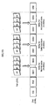
- FIG. 1 illustrates the interactive control described above. In the figure, the lowest level shows data allocation on the DVD. It is shown that state control information is contained in a NAVI pack. The state control information remains valid during a time period of the GOP to which the NAVI pack belongs. Each graphics object is contained in a PES packet, and displayed at the same timing with a picture to be synchronized with the graphics object. This prior art technique is disclosed for example in JP patent No. 2813245 .
- US-B1-6 226 446 describes a multimedia optical disk which includes a data area for storing objects. These objects include moving picture data and audio or sub-picture data. Sub-picture data include a plurality of menu items composing a menu. An index area on the disk stores the reproduction order of the objects in accordance to stored reproduction route data allowing for several branches. The user selects between reproduction routes via a remote controller of a reproduction apparatus. A piece of moving picture data having a certain time period is reproduced at the same time as a piece of audio data and a piece of sub-picture data. Moving pictures are synchronized with instructions to the apparatus by the user in order to achieve an interactive software title.
- EP-A-0 898 279 describes a recording medium retaining data for menu buttons of a menu displayed on a screen during replaying information such as multiplexed video and audio data from the recording medium.
- Response pictures in response to an operation of a menu button may include moving pictures with sound. Also, the display patterns of a menu button may vary. After the response picture having been displayed, the function assigned to the menu button is executed.
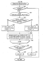
- the present invention aims to provide a recording medium which allows the button state changes to be tested at an early stage of authoring.
- the scheme is not as effective when considering a rate at which a BD-ROM is read.
- the BD-ROM's read rate is much higher than that of DVD' s, so that it is no longer important to restrict the bandwidth.
- a recording medium has recorded thereon a digital stream into which a video stream and a graphics stream are multiplexed.
- the graphics stream includes graphics data and state control information integrated therein.
- the graphics data is used to compose an interactive display.
- the state control information is used to cause the interactive display to change to a different state in response to a reproduction proceeding of the video stream and a user operation.
- the information for causing the button state change is integrated with the graphics data into the graphics stream.
- the state control information in each of the plurality of display sets may include an update flag.
- the update flag indicates that the display set is identical to an immediately preceding display set with respect to the state control information and the graphics data, except for a button command.
- the update flag indicates that the display set is identical to an immediately preceding display set with respect to the state control information and the graphics data.
- the button command may be for execution by a reproduction apparatus upon activation of an associatedbutton on the interactive display.
- a title is a quiz game and two display sets present a question for a user to answer.
- the title may be constructed to branch to a more and more disadvantageous reproduction path for the user as the user response delays.
- each of the n buttons may have a number assigned thereto.
- Each of the n pieces of button information may include a number assigned to an associated button and a flag showing whether the button is numerically selectable with the number.
- buttons commands are prepared that the reproduction branches to scenes showing play of the baseball players.
- the player numbers are assigned to the button commands .
- the reproduction path to the scenes of a specific baseball player is taken at a numeric input of the player number.
- FIG. 2A shows a usage pattern of the recording medium according to the present invention.
- a BD-ROM 100 is a recording medium according to the present invention.
- the BD-ROM 100 is used for providing movies to a home theater system composed of a reproduction apparatus 200, a television 300, and a remote controller 400.
- the remote controller 400 receives user operations instructing to change the state of interactive display, and is closely related to the recording medium according to the present invention.
- FIG. 2B shows keys of the remote controller 400.
- the remote controller 400 has a Move Up key, a Move Down key, a Move Right key, and a Move Left key.
- Each button displayed on the interactive display has three states: the normal state; the selected state; and the activated state.
- the Move Up, Move Down, Move Right, and Move Left keys are used to receive user operations for causing the button state to change in the order of the normal state - the selected statue - the activated state, for example.
- the button When a button has the normal state, the button is simply displayed.
- the button is currently focused as a result of a user operation but not yet activated.
- the activated state the button has been activated.
- the Move Up key is used to put a button displayed above the currently selected button to the selected state.
- the Move Down key is used to put a button displayed below the currently selected button to the selected state.
- the Move Right key is used to put a button displayed right to the currently selected button to the selected state.
- the Move Left key is used to out a button displayed left to the currently selected button to the selected state.
- An Activate key is used to put a button having the selected state to the activated state (to activate the currently selected button) .
- Numeral keys “0" to “9” are used for numeric selection so as to put a button having assigned an inputted value to the selected state.
- a “+10” key is used to add the value of 10 to a value having been entered. Note that the "0" key and the “+10” key are both used to enter a two-digit value. Thus, one of the "0” and “+10” keys may be sufficient instead of both.
- FIG. 3 shows an example structure of the BD-ROM 100.
- the BD-ROM 100 is shown on the fourth level, and a BD-ROM's track is shown on the third level.
- the track is stretched out into a straight line, although the track in practice spirals outwards from the center of the BD-ROM.
- the track is composed of a lead-in area, a volume area, and a lead-out area.
- the volume area has a layer model of a physical layer, a file system layer, and an application layer.
- the first level shows, in a directory structure, a format of the application layer (application format) of the BD-ROM.
- the BD-ROM has a BDMV directory below a ROOT directory.
- the BDMV directory contains files, such as XXX.M2TS, XXX.CLPI, and YYY.MPLS.
- the BD-ROM of the present invention can be produced by creating an application format as shown in the figure.
- the AV Clip (XXX.N2TS) is a digital stream compliant with an MPEG-TS (transport stream) format, and obtained by multiplexing a video stream, one or more audio streams, a presentation graphics stream, and an interactive graphics stream.
- the video stream represents video of a movie.
- the audio stream represents audio of the movie.
- the presentation graphics stream represents subtitles of the movie.
- the interactive graphics stream represents dynamic control procedures for reproduction of menus.
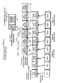
- FIG. 4 schematically shows a structure of the AV Clip.
- the AV Clip shown in the figure on the middle level is obtained in the following manner.
- the video stream shown on the upper first level is composed of a plurality of video frames (picture pj1, pj2, pj3, ...)
- the audio stream also shown on the upper first level is composed of a plurality of audio frames.
- the video and audio streams are separately converted to PES packets shown on the upper second level.
- the PES packets are further converted to TS packets shown on the upper third level.
- the presentation graphics stream and the interactive graphics stream shown on the lower first level are separately converted to PES packets shown on the lower second level, and further converted to TS packets shown on the lower third level.
- These TS packets shown on the upper and lower third levels are multiplexed to form the AV Clip.
- the AV Clip generated as above is divided into a plurality of extents in the same way as computer files, and recorded onto the BD-ROM.
- the AV Clip is composed of one or more Access Units, and the reproduction of AV Clip may skip to a point corresponding to ant Access Unit.
- An Access Unit is composed of one GOP (Group Of Pictures) and an audio frame to be read simultaneously with the GOP, and is a minimum unit for decoding.
- GOPs include three types of pictures: Bidirectionally Predictive picture (B picture) that is coded using correlation with both past and future pictures; Predictive picture (P picture) that is coded using correlation with past pictures; and Intra picture (I picture) that is coded using its own spatial frequency characteristic without referencing the inter-frame correlation.
- Clip information (XXX.CLPI) is management information of each AV Clip.
- Fig. 5 shows an internal structure of Clip information. Since an AV Clip is obtained by multiplexing a video stream and an audio stream and accessible at random in the units calledAccess Units, the Clip information includes information, such as the attributes of video and audio streams and the points within the AV Clip to which a skip operation may be performed.
- the doted lines indicate that the structure of Clip information is excerpted to be shown in detail.
- the Clip information (XXX.CLPI) is composed of "attribute information" of the video and audio streams, and "EP_map" that is a reference table for searching Access Units.
- the attribute information is composed of an attribute of the video stream (Video Attribute), the number of attributes (Number), and attributes (Audio Attribute #1-#m) of all the audio streams multiplexed in the AV Clip.
- the video attribute is composed of information showing the coding method in which the video stream is coded (Coding), the resolution of pictures constituting the video stream (Resolution), the aspect ratio (Aspect), and the frame rate (Framerate).
- each of the attributes of audio streams is composed of information showing the coding method in which a corresponding audio stream is coded (Coding), the channel number of the audio stream (Ch.), the language of the audio stream (Lang.), and the sampling frequency.
- the EP_map is a reference table for indirectly referencing by time the addresses of accessible points in skip operations.
- the EP_map is composed of a plurality of entries (Access Unit #1 entry, Access Unit #2 entry, Access Unit #3 entry ...), and the number of entries (Number).
- each entry shows the reproduction start time and the address of a corresponding Access Unit (Note that the size of a first I picture in the Access Unit (I-size) may be additionally shown).
- the reproduction start time is shown by a time stamp for a picture located at the beginning of the Access Unit (Presentation Time Stamp).
- the address is shown by a serial number of a corresponding TS packet (SPN: Source Packet Number).
- the Access Units each containing a GOP are not uniform both in size and reproduction time period. Yet, with reference to the entries corresponding to the Access Units, an Access Unit located at a point corresponding to any given reproduction time can be searched, so that the reproduction can be started from the first picture in the searched Access Unit.
- "XXX” in the file name "XXX.CLPI" is the same as the name of AV Clip to which the Clip information corresponds.
- the file name of the AV Clip is "XXX", which means that the Clip information (XXX.CLPI) corresponds to the AV Clip (XXX M2TS). This concludes the description of Clip information.
- PlayList information will be described.
- YYY.MPLS is a table serving as a PlayList defining reproduction paths, and is composed of a plurality of pieces of PlayItem information (PlayItem Information #1, #2, #3,... #n) and the number of PlayItem information pieces (Number).
- FIG. 6 shows an internal structure of the PlayListinformation. PlayList information shows one or more logical segments for reproduction each defined by PlayItem information. As the doted lines hs1 indicate, the structure of PlayItem information is excerpted to be shown in detail.
- the PlayItem information is composed of: "clip_information_file_name” showing the file name of a reproduction segment within the AV Clip to which the in_time and out_time of the reproduction segment belong; “clip_codec_identifier” showing the coding method by which the AV Clip is coded; “in_time” showing the time corresponding to the start point of the reproduction segment; and “out_time” showing the time corresponding to the end point of the reproduction segment.
- FIG. 7 is a view schematically illustrating the indirect reference by time.
- the AV Clip is composed of a plurality of Access Units.
- the EP_map in the Clip information specifies the sector address of each Access Unit as indicated by arrows ay1, ay2, ay3, anday4.
- Each of the arrows jy1, jy2, jy3, and j y4 is a schematic representation of an indirect reference to an Access Unit.
- each piece of PlayItem Information has a reference (arrows jy1, jy2, jy3, and jy4) specifying by time via the EP_map, the address of a corresponding Access Unit contained in the AV Clip.
- a reproduction segment on the BD-ROM specified by a set of PlayItem information - Clip information - AV Clip is called "PlayItem”.
- a logical unit of reproduction on the BD-ROM specified by a set of PL information - Clip information - AV Clip is called "PlayList (hereinafter, PL)”.
- PL logical unit of reproduction on the BD-ROM specified by a set of PL information - Clip information - AV Clip
- a movie recorded on the BD-ROM is segmented into the logical units of PLs. Since the movie is segmented into the logical units, it is possible to define such a PL specifying scenes in all of which a specific character makes an appearance. In this way, separately from the main movie, another movie is readily made in which the character appears at all times.
- FIG. 8A is a view showing a structure of the graphical stream.
- a string of TS packets constituting an AV Clip is shown on the first level.
- a string of PES packets constituting a graphics stream is shown on the second level.
- the PES packets shown on the second level are formed by concatenating payloads of TS packets having a predetermined PID within the TS packet string shown on the first level. Note that no description is given to a presentation graphics stream because it is not the gist of the present invention.
- the graphics stream is composed of functional segments that include an ICS (Interactive Composition Segment), a PDS (Palette Definition Segment), an ODS (Object Definition Segment), and an END (End of Display Set Segment).
- the ICS is a screen composition segment
- the PDS, ODS, and END are definition segments.
- Each functional segment is either in one-to-one or one-to-multiple correspondence with PES packets. That is, one functional segment is recorded on the BD-ROM 100 after being converted to a single PES packet, or fragmented and converted to a plurality of PES packets.
- FIG. 8B is a view showing the PES packets obtained by converting functional segment (s).
- each PES packet is composed of a packet header and a payload.
- the payload is an entity of a functional segment, and the packet header contains a DTS and PTS associated with that functional segment.
- the DTS and PDS contained in the header of a PES packet containing a functional segment are referred to as the DTS and PTS of that functional segment.
- Each display set (hereinafter "DS") shown on the second level is a group of functional segments which together constitute one complete screen of graphics.
- Dashed lines hk2 indicate a DS to which the functional segments on the third level belong.
- the series of functional segments, ICS-PDS-ODS-END constitutes one DS.
- the reproduction apparatus can produce one screen of graphics.
- An Epoch shown on the first level refers to a time period during which the continuity in memory management must be maintained on the reproduction time axis of AV Clip, or to a set of data allocated to the time period.
- Memory mentioned here includes a graphics plane for storing one screen of graphics and an object buffer for storing uncompressed graphics data.
- the continuous memory management means that throughout the Epoch neither the graphics plane nor the object buffer is flushed, and erasing and rendering of graphics are performed only within a predetermined rectangular area of the graphics plane (to flush means to clear the entire graphics plane and the entire object buffer).
- the size and position of this rectangular area are fixed throughout the Epoch. So long as erasing and rendering of graphics are performed within this fixed rectangular area of the graphics plane, seamless reproduction is ensured.
- the Epoch is a time unit, on the reproduction time axis of the AV Clip, during which seamless reproduction is ensured.
- To change the graphics rendering area in the graphics plane it is necessary to define a point of change on the reproduction time axis and set a new Epoch from the point onward. In this case, a boundary between the two Epochs is not seamless.
- the seamless reproduction used herein means that the erasing/rendering of graphics is completed with a predetermined number of video frames.
- the number of video frames is four to five.
- the number of video frames is determined based on the ratio of the fixed region to the entire graphics plane and the transfer rate between the object buffer and the graphics plane.
- dashed lines hk1 and hk2 indicate an Epoch to which the functional segments shown on the second level belong. It is shown that a series of DSs, which are an Epoch Start DS, an Acquisition Point DS, and a Normal Case DS, constitutes one Epoch on shown on the first level.
- Epoch Start "Acquisition Point”
- Normal Case are types of DSs.
- the Acquisition Point DS precedes the Normal Case DS in FIG. 9 , they may be arranged in the reverse order.
- the "Epoch Start” DS provides a display effect "new display”, and indicates a start of a new Epoch.
- the Epoch Start DS thus contains all functional segments needed for the next screen composition.
- the Epoch Start DS is provided at a point in the AV Clip to which a skip operation may be performed, such as a start of a chapter in a movie.
- the Acquisition Point DS provides a display effect "display refresh", and relates to the preceding Epoch Start DS.
- the Duplicate type DS is a completely identical DS to the preceding Epoch Start DS.
- the Inherit DS inherits the functional segments of the preceding Epoch Start DS but has different button commands.
- the Acquisition Point DS contains all functional segments needed for the next screen composition.
- the Acquisition Point DS enables a screen composition from a midpoint in the Epoch.
- the Acquisition Point DS is provided in a point to which a skip operation may be made. Examples of such points include one that may be designated by a time search.
- the time search is an operation of locating a reproduction point corresponding to a time inputted by a user in minutes/seconds. Since the user input is made in a relatively large unit such as ten minutes and ten seconds, searchable reproduction points are located at intervals of 10 minutes or 10 seconds.
- the Normal Case DS provides a display effect "display update", and contains only a difference from the previous screen composition. For example, if a button defined by a DS (v) has the same graphical representation as a button defined by an immediately preceding DS (u), but has a different state control. In this case, the DS (v) contains ICS or ICS and PDS only, and serves as a Normal Case DS. With this arrangement, the Normal Case DS is not required to contain overlapping ODSs, which leads to the reduction in the amount of data stored on the BD-ROM. Since the Normal Case DS only contains the difference, graphics cannot be displayed with the Normal Case DS alone.
- the interactive display defined by the above-described DSs presents GUI elements.
- the interactivity of DSs refers to the capability of changing the state of each GUI element in accordance with a user operation.
- GUI elements interacted by user operations are referred to as buttons.
- Each button has the normal state, the selected state, and the activated state.
- Each button state is rendered using a plurality of pieces of uncompressed graphics data, which is referred to as a "graphics object" .
- One state of one button is associated with a plurality of graphics objects for presentation in animation.
- ODS Object Definition Segment
- PDS Palette Definition Segment
- the ODS is information defining a graphics object, which will be described later. Since AV Clips recorded on a BD-ROM feature its high image quality comparable to high-definition television, the graphics objects have a high resolution of 1920 ⁇ 1080 pixels.
- the color of each pixel is defined by 8-bit long index values showing a red color difference component (Cr value), a blue color difference component (Cb value), a luminance component (Y value), and a transparency (T value). This structure allows each pixel to be set to one of arbitrary 256 colors out of 16,777,216 colors.
- the ODS has a data structure shown in FIG. 10A .
- the ODS is composed of the following fields: "segment_type” showing that the type of this segment is an ODS; "segment_length” showing the data length of the ODS; "object_id” uniquely identifying a graphics object within the Epoch, associated with the ODS; “object_version_number” showing the version of the ODS within the Epoch; "last_in_sequence_flag”; and "object_data_fragment” carrying a consecutive sequence of bytes corresponding to part or all of the graphics object.
- the object_id field uniquely identifies a graphics object within the Epoch, associated with the ODS.
- these ODSs are assigned serial object_id values.
- the last_in_sequence_flag field and the object_data_fragment field in more detail. Due to the constraint on a payload of PES packet, there may be a case where a piece of uncompressed graphics data constituting one button can not be carried by a single ODS. If this is the case, the graphics data is fragmented and each fragment is defined by an ODS in the object_data_fragment field. Here, every fragment except the last fragment is of the same size. That is, the last fragment is less than or equal to the size of the preceding fragments. The ODSs carrying these fragments of the graphics object appear in the DS in sequence.
- the last_in_sequence_flag field indicates an end of the graphics object.
- ODS data structure is based on a method of storing fragments in consecutive PES packets without a gap
- the fragments may instead be stored in PES packets so as to leave some gaps between the PES packets. This concludes the description of ODS.
- the PDS is information defining a palette for color conversion.
- FIG. 10B shows a data structure of the PDS. As shown in the figure, each PDS is composed of the following fields: “segment_type” showing, when set to the value "0x15", that the type of this segment is a PDS; “segment_length” showing the data length of the PDS; “pallet_id” uniquely identifying the pallet contained in the PDS; “palette_version _number” showing the version of the PDS within the Epoch; and “pallet_entry” showing the Color Difference Red (Cr_value), the Color Difference Blue (Cb_value), Luminance (Y_value), and Transparency (T_value).
- the ICS is a functional segment defining the composition of an interactive display.
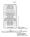
- the ICS has a data structure shown in FIG. 11 .
- the ICS is composed of the following fields, "segment_type”, “segment_length”, “composition_number”, “composition_state”, “command_update_flag”, “composition_time_out_pts”, “selection_time_out_pts”, “UO_mask_table”, "animation_frame_rate_code”, “default_selected_button_number”, “default_activated_button_number”, and a group of "button info (1), (2), (3)".
- composition_number field is set to a value out of 0-15 showing that the DS to which the ICS belongs is updated.
- composition_state field shows that the DS beginning with the ICS is the Normal case DS, the Acquisition Point DS, or the Epoch Start DS.
- the command_update_flag field indicates that the button commands in the ICS are changed from those defined in the previous ICS.
- the DS to which an ICS belongs is an Acquisition Point DS
- the ICS is normally equal to those defined in the immediately previous ICS.
- the command_update_flag is set to ON when different button commands are associated with the same graphics objects.
- composition_time_out_pts field describes the end time of the interactive display. At the end time, the interactive composition is no longer valid and thus no longer displayed.
- the composition_time_out_pts is preferably described with the frame accuracy of the video stream on the reproduction time axis.
- the selection_time_out_pts field describes the termination time of the valid button selection period. At the time of the selection_time_out_pts, the button specified by the default_activated_button_number is activated. The value of the selection_time_out_pts is less than or equal to the value of the composition_time_out_pts. The selection_time_out_pts is described with the frame accuracy of the video stream on the reproduction time axis.
- the UO_mask_table determines permissions/prohibitions of User Operations for the duration of DS to which the ICS belongs. When this field is set to "Prohibited", a corresponding User Operation to the reproduction apparatus is invalid.
- the animation_frame_rate_code field specifies the frame rate to be applied to animated buttons.
- the animation frame rate is given by the video frame rate divided by the value of the animation_frame_rate_code field.
- this field is set to "00" only the graphics object designated by the start_object_id_xxx is displayed for every button in non-animated state.
- the default_selected_button_number field indicates the button number that is selected as default when the presentation of the interactive display begins.
- this field is set to the value "0"
- the button specified by the button number stored in a register of the reproduction apparatus is automatically activated.
- this field is set to a value other than "0"
- the value indicates a valid button number.
- the default_activated_button_number field indicates the button which is automatically activated when no button is activated by the user before the time defined by the selection_time_out_pts field.
- this field is set to "FF”
- the currently select button is activated at the time defined by the selection_time_out_pts field.
- this field is set to "00”
- no button is automatically activated. If this field is set to a value other than "FF" and "00", the value is interpreted as a valid button number.
- the button_info field provides information defining buttons to be presented on the interactive display.
- the doted lines hp1 indicate that a data structure of button_info (i) is excerpted to be shown in detail.
- the button_info (i) carries information about the button (i) defined by the ICS.
- a description is given to the information items constituting the button_info (i).
- the button_number field indicates the value uniquely identifying the button (i) within the ICS.
- the numerically_selectable_flag field indicates whether the button (i) can be numerically selected.
- the auto_action_flag field indicates whether to automatically activate the button (i).
- the button (i) is transferred not to the selected state but directly to the activated state.
- the auto_action_flag is set to OFF (bit value of "0"), the button (i) is transferred not to the activated state but to the selected state when selected by a user.
- the button_horizontal_position field and button_vertical_position field respectively specify the horizontal and vertical positions of the top left pixel of the button (i) in the interactive display.
- the upper_button_number field specifies the button number of a button to receive the selected state at a push of the Move Up key while the button (i) is in the selected state. If this field is set to the same button number as that of the button (i), the user operation to the Move Up key is ignored.
- the lower_button_number field, the left_button_number field, the right_button_number field specify the button number of a button to receive the selected state at a push of the Move Down key, Move Left key, and Move Right key, respectively, while the button (i) is in the selected state. If these fields are set to the same button number as that of the button (i), the user operations to the respective keys are ignored.
- the start_object_id_normal specifies the first one of object_ids assigned serially to a group of ODSs constituting the animation of button (i) in the normal state.
- the end_object_id_normal field specifies the last one of the object_ids assigned serially to the group of ODSs constituting the animation of button (i) in the normal state. If the end_object_id_normal field specifies the same value as that of the start_object_id_normal, the static image of the graphics object identified by the value is presented as the button (i).
- the repeat_normal_flag field specifies whether the animation of the button (i) in the normal state is to be continuously repeated.
- the start_object_id_selected field specifies the first one of object_ids assigned serially to a group of ODSs constituting the animation of button (i) in the selected state. If the end_object_id_selected field specifies the same value as that of the start_object_id_selected, the static image of the graphics object identified by the value is presented as the button (i).
- the end_object_id_selected field specifies the last one of the object_ids assigned serially to the group of ODSs constituting the animation of button (i) in the selected state.
- the repeat_selected_flag field specifies whether the animation of the button (i) in the selected state is to be continuously repeated.
- the start_object_id_activated field specifies the first one of object_ids assigned serially to a group of ODSs constituting the animation of button (i) in the activated state.
- the end_object_id_activated field specifies the last one of the object_ids assigned serially to the group of ODSs constituting the animation of button (i) in the activated state.
- Each button_command is executed when the button (i) is activated.
- the button commands may include one instructing the reproduction apparatus to reproduce a PL or PlayItem.
- a command instructing the reproduction apparatus to reproduce a PL and PlayItem is referred to as a LinkPL command.
- reproduction of the PlayList specified by the first argument is started from the point specified by the second argument.
- the first argument is the PL number specifying the PL to be reproduced.
- the second argument specifies, as a reproduction start point, a PlayItem, a Chapter, or a Mark within the PL.
- the LinkPL function for specifying a PlayItem as a reproduction start point is "LinkPL at PlayItem ()".
- the LinkPL function for specifying a chapter as a reproduction start point is "LinkPL at Chapter ()".
- the LinkPL function for specifying a mark as a reproduction start point is "LinkPL at Mark ()".
- the button commands may also include a command instructing the reproduction apparatus to obtain or set the state of the apparatus.
- the state of reproduction apparatus is shown by 64 player status registers (whose values are referredtoasPSRs) and 4, 096 general purpose registers (whose values are referred to as GPRs) . With the following commands (i) - (iv), specific values are set to the registers or the values of the registers are obtained.
- FIG. 12 is a view showing the relation between the ODSs and ICS contained within a DS (n).
- the DS (n) includes the ODSs 11-19, 21-29, 31-39, 41-49.
- the ODSs 11-19 are for rendering a button A in each of the three states.
- the ODSs 21-29 are for rendering a button B in each of the three states.
- the ODSs 31-39 are for rendering a button C in each of the three states.
- the ODSs 41-49 are for rendering a button D in each of the three states (See the right brackets in the figure).
- the button_info (1), (2), (3), and (4) in the ICS provide the descriptions of state control of the buttons A-D (See arrows bh1, bh2, bh3, and bh4 in the figure).
- the control defined by the ICS is to be executed in synchronism with the display timing of a picture pt1 included in the video stream shown in FIG. 13 .
- an interactive display tm1 composed of the buttons A-D is overlaid (gs1) with the picture pt1 to produce a composite screen gs2.
- the interactive display composed of multiple buttons is presented in synchronism with a specific video image.
- the ICS makes it possible to present buttons in a way more real to the users.
- FIG. 14 shows an example of the description realizing the state transition of buttons A-D as illustrated in FIG. 15 .
- the arrows hh1 and hh2 each visually represent the state transition defined by the neighbor_info () within the button info (1).
- the lower_button_number field specifies the button C. Consequently, a user operation to the Move Down key (up1 in the figure) while the button A is in the selected state, the button C receives the selected state (sj1 in the figure).
- the right_button_number field specifies the button B. Consequently, a user operation to the Move Right key (up2 in the figure) while the button A is in the selected state, the button B receives the selected state (sj2 in the figure).
- the arrow hh3 in FIG. 15 visually represent the state transition defined by the neighbor_info () within the button info (3).
- the upper_button_number field specifies the button A. Consequently, a user operation to the Move Up key (up3 in the figure) while the button C is in the selected state, the button A is put back into the selected state.
- buttons A-D The ODSs 11, 21, 31, and 41 each present images shown in FIG. 16 .
- the ODSs 11-19 associated with the button A present images shown in FIG. 17 .
- the start_object_id normal and end_object_id normal fields specify the ODSs 11 and 13, respectively. Consequently, the button A in the normal state is presented in animation by the sequence of the ODSs 11-13.
- the start_object_id_selected and end_object_id_selected fields specify the ODSs 14 and 16, respectively. Consequently, the button A in the selected state is presented in animation by the sequence of ODSs 14-16.
- each of the buttons A-B is associated with of a sequence of ODSs which can be presented in animation.
- ICS describing the control as above, such button state control is realized that a character image serving as a button changes its facial expression in response to user operations.
- FIG. 18 is a view showing an example of the ICS and ODSs included in a DS.
- the ODSs 31-33 represents images of three baseball players along with their names and player numbers, as shown in the upper part of the figure.
- the ICS belonging to the DS includes three pieces of button information, button_info (1), (2), and (3).
- the start_object_id fields of button_info (1), (2), and (3) specify the ODS 31, ODS 32, and ODS 33, respectively.
- the button _number fields of the button_info (1), (2), and (3) are set to the values of "99", "42", and "94", respectively.
- buttons_info (1), (2), and (3) are all set to the value "1".
- each button defined by button_info (1), (2), and (3) is numerically selectable.
- the button presented with the image of Mr. beginnerer's Luck receives the selected state.
- the value "99” may be inputted by pressing the "4" key and “9” key in a row or by pressing the "9” key once and “+10” key four time in a row.
- the button of Mr. Careless Mistake receives the selected state.
- the button of Mr. Dead Stock receives the selected state.
- buttons receive, when selected, the active state instead of the selected state, and the button commands (LinkPL (PL#21), LinkPL (PL#22), LinkPL (PL#23)) included in the button_info are executed.
- the button commands (LinkPL (PL#21), LinkPL (PL#22), LinkPL (PL#23)) included in the button_info are executed.
- PL #21, #22, or #23 to which the executed button command is linked is reproduced.
- those PLs define scenes of batting or pitching by the above players, each of these scenes is reproduced at an input of the numeric value corresponding to one of the player numbers. Since the buttons are selectable with an input of the player numbers, which are easy for the users to recognize, there is provided improved user operability.
- the order of ODSs in the DS is determined in accordance with the button state with which each ODS is associated.
- the ODSs belonging to one DS are grouped into (1) ODSs for presentation of a button in the normal state, (2) ODSs for presentation of the button in the selected state, and (3) ODSs for presentation of the button in the activated state.
- Each group for presentation of a respective state is referred to as a "button-state group".
- the button-state groups are arranged in the order, for example, of the normal state ⁇ the selected state ⁇ the activated state. As above, the order of ODSs within the DS is determined according to the button state with which the ODSs are associated.
- FIG. 19 is a view showing the order of ODSs within a DS.
- the following three button-state groups within the DS are shown on the second level: the button state group for presentation of the normal state (ODSs for Normal state) ; the button state group for presentation of the selected state (ODSs for Selected state) ; and the button state group for presentation of the activated state (ODSs for Activated state).
- the button-state groups are arranged in the order of the normal state ⁇ the selected state ⁇ the activated state. This order is determined so that the reproduction apparatus first reads the interactive composition constituting the first interactive display, and then reads the interactive composition to be presented only after update.
- FIG. 19 shows on the first level the graphics objects An, Bn, Cn, Dn, As, Bs, Cs, Ds, Aa, Ba, Ca, and Da that are referenced by the button-state groups.
- the numerical subscript n as in An, Bn, Cn, and Dn indicates a respective button in the normal state.
- the numerical subscript s as in As, Bs, Cs, Ds indicates a respective button in the selected state
- the numerical subscript a as in Aa, Ba, Ca, and Da indicates a respective button in the activated state.
- the figure shows on the second level the button-state groups to which the graphics objects shown on the first level belong.
- FIG. 20 is a view illustrating the button state transition on the interactive display defined by the button-state groups shown in FIG. 19 .
- the interactive display has a plurality of states including “initial state”, “display update by 1st user action”, and “display update by 2nd user action”.
- the arrows in the figure represent user actions triggering the state transition.
- the four buttons A, B, C, and D each have the normal state, the selected state, and the activated state.
- the graphics objects for the three buttons in the normal state and one button in the selected state need to be ready for presentation.
- the initial interactive display can be made upon completion of decoding the graphic objects for the normal and selected states of each button.
- the button-state groups in this embodiment are arranged in the order of the normal state ⁇ the selected state ⁇ the activated state, as shown in FIG. 19 . With this arrangement, the initial interactive display can be presented even if the ODSs for the activated state are not yet read and decoded. As a result, the duration is shortened between the reading of DS is commenced and the presentation of initial interactive display is completed.
- FIG. 21 is a view showing the order of ODSs within a DS.
- the ODSs for normal state include ODSs 11-13, 21-23, 31-33, and 41-43.
- the ODSs for selected state include ODSs 14-16, 24-26, 34-36, and 44-46.
- the ODSs for activated state includes ODSs 17-19, 27-29, 37-39, and 47-49.
- the ODSs 11-13 are for animated presentation of the character image shown in FIG. 17 .
- the ODSs 21-23, 31-33, and 41-43 are for animated presentation of other character images.
- the initial interactive display is ready for presentation even before the reading of the DS is completed. This ensures that the interactive display composed of animated buttons is displayed without delay.
- multiple references means that the same object_id is referenced by two or more pieces of normal_state_info, selected_state_info, and activated_state_info within the ICS.
- a specific graphics object used to render a button in the normal state is commonly used to render another button in the selected state.
- the graphics object is shared, so that the number of ODSs can be reduced.
- a problem arises as to which button-state group an ODS with multiple references belongs.
- the ODS is placed in the button-state group that first appears. For example, if the button-state groups appear in the order of the normal state ⁇ the selected state ⁇ the activated state, an ODS referenced by both the normal-state and selected-state groups is placed in the normal-state group. Also, an ODS referenced by both the selected-state and activated-state groups is placed in the selected-state group. This concludes the description of the order of multiple referenced ODSs.
- buttons-state group for the selected state which of the ODSs should be placed at the beginning depends on whether a default selected button is determined.
- the default selected button is specified when the default_selected_button_number field is set to a valid value other than "00". In this case, the ODS associated with the default selected button is placed at the beginning of the button-state group.
- No default selected button is specified when the default selected button_number field in ICS is set to the value "00".
- the default_selected_button_number field is set to the value "00" in the case, for example, where an AV Clip into which the DS is multiplexed serves as a merge point of a plurality of reproduction paths.
- the preceding reproduction paths correspond to Chapters 1, 2, and 3
- a DS serving as a merge point is for presentation of buttons associated with Chapters 1, 2, and 3.
- no specific button can be specified in the default_selected_button_number field.
- the button associated with Chapter 2 should be selected as default.
- the button associated with Chapter 3 should be selected as default, and the button associated with Chapter 4 after reproduction of Chapter 3.
- the default_selected_button_number field is set to the value "0" to be invalidated when a different button needs to be selected as default depending on which reproduction path has been taken. In this case, it is not necessary to place a specific button-state group ODSs at the beginning because no specific button is selected as default.
- An Epoch is a time period on the reproduction time axis during which memory management is continuous. Since each Epoch is composed of one or more DSs, it is important to how to allocate those DSs on the reproduction time axis of AV Clip.
- the reproduction time axis of AV Clip mentioned here is a time axis for defining decoding timing and presentation timing of individual pictures which constitute the video stream multiplexed in the AV Clip. The decoding timing and presentation timing on the reproduction time axis are expressed with a time accuracy of 90 KHz.
- This time accuracy of 90 KHz corresponds to a common multiple of NTSC signal, PAL signal, Dolby AC-3, and the frame frequency of MPEG audio.
- a DTS and a PTS attached to ICS and ODS within a DS specify timings on this reproduction time axis for achieving synchronous control.
- the DSs are allocated on the reproduction time axis by exercising synchronous control using DTS and PTS attached to ICS and ODS.
- the DTS shows a time, with the time accuracy of 90 KHz, at which the decoding of ODS needs to be started.
- the PTS shows a deadline for completing the decoding.
- the decoding of ODS can not be completed instantly, and takes a certain duration.
- the DTS and PTS of the ODS show the decoding start time and decoding deadline.
- PTS shows the deadline by which the decoding of ODS (j) needs to be completed and the resulting uncompressed graphics object needs to be available in the object buffer of the reproduction apparatus.
- the decoding start time of an arbitraryODS (j) belonging to a DS (n) is shown by DTS (DS n [ODS]) with the time accuracy of 90 KHz.
- the decoding deadline of the ODS (j) is determined by adding to the DTS (DS n [ODS]) value, a maximum time which may be taken for the decoding.
- SIZE (DS n [ODS j ]) denote the size of ODS (j), and Rd denote the ODS decoding rate. Then the maximum time required for the decoding (in seconds) is SIZE (DS n [ODS j ])//Rd.
- the decoding deadline to be shown by the PTS is calculated with the accuracy of 90 KHz.
- PTS DS ODS ⁇ j DTS DS ⁇ n ODS ⁇ j + 90 , 000 ⁇ SIZE DS ⁇ n ODS ⁇ j / / Rd
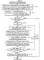
- the PTS within the ICS is set to the value obtained by adding (1) the PTS value of the ODS of which decoding time is latest among all the ODSs needed for the initial display of the DS (n), (2) the time taken to clear the graphics plane, and (3) the time taken to transfer the decoded graphics object to the graphics plane.
- the initial interactive displayed can be presented upon completion of the decoding of ODSs associated with each button in the normal state and the specified default selected button in the selected state.
- the ODSs for rendering each button in the selected state are referred to as S-ODSs, and the S-ODS of which decoding start time is earliest (i.e. the ODS for rendering the default selected button, in this case) is referred to as S-ODSsfirst.
- the PTS value of this S-ODSsfirst is designated as the PTS value of the ODS of which decoding start time is latest, and used as a reference value for the PTS within the ICS.
- the default_selected_button_number When the default_selected_button_number is not specified in the ICS, it is not known which of the buttons willbefirstselected. Thus,theinitialinteractive display is not available for presentation until it is ready to render every button in the normal state as well as the selected state.
- the S-ODSs for rendering the selected state of each button included in the initial interactive display the ODS of which decoding start time is latest is referred to as the S-ODSslast.
- the PTS value of this S-ODSslast is designated as the PTS value of the ODS of which decode start time is latest, and used as a reference value for the PTS within the ICS.
- PTS (DSn [S-ODSsfirst]) denote the decoding deadline of S-ODSsfirst, then PTS (DS n [ICS]) is set to the value obtained by (2) the time taken to clear the graphic plane and (3) the time taken for rendering the decoded graphics object to the graphics plane.
- video_width and video_height denote the width and height of a rectangular area of graphics plane within which graphics objects are rendered.
- the rendering rate to the graphics plane is 128 Mbps
- the time taken to clear the graphics plane is obtained by 8 ⁇ video_width ⁇ video_height // 128,000,000.
- the above-mentioned time (2) taken to clear the graphics plane is expressed by 90,000 ⁇ (8 ⁇ video_width ⁇ video_height //128,000,000).
- ⁇ SIZE(DS n [ICS.BUTTON[ i ]] denote the total size of graphics objects specified by each piece of button information contained in the ICS.
- the rendering rate to the graphics plane is 128 Mbps
- the time taken to render the graphics plane is obtained by ⁇ SIZE(DS n [ICS.BUTTON[ i ]]) // 128,000,000.
- the above-mentioned time (3) taken to render the graphics plane is expressed by 90, 000 ⁇ ( ⁇ SIZE(DS n [ICS.BUTTON[ i ]]) // 128,000,000).
- PTS (DSn [ICS]) is expressed by the following formula: PTS DS ⁇ n ICS ⁇ PTS ⁇ DS ⁇ n ⁇ S - ODSsfirst + 90 , 000 ⁇ 8 ⁇ video_width ⁇ video_height / / 128 , 000 , 000 + 90 , 000 ⁇ ⁇ SIZE DS ⁇ n ICS . BUTTON i / / 128 , 000 , 000 , 000
- FIG. 22 illustrates an example of such control.
- buttons are to be displayed in synchronization with the display timing of a picture py1 in the video stream.
- the PTS within the ICS needs to be set to the value corresponding to the display point of picture data py1.
- the DTS within the ICS is set to show the time prior to the time shown by the PTS.
- the decoding of ODSs constituting the initial interactive display of DS (n) needs to be completed by the time calculated by subtracting from the time shown by the PTS in the ICS, the plane clear duration cd1 and the object transfer duration td1.
- the PTS of the ODS of which decoding time is the latest needs to be set to the value corresponding to a point of time marked in the figure with a black star.
- a duration dd1 is taken for decoding the ODS, so that the DTS of the ODS needs to be set to a time earlier than the PTS by the duration dd1.
- FIG. 22 is a simplified case in that only one ODS is used for overlay with the video data.
- the PTS and DTS of the ICS and of ODS need to be set as illustrated in FIG. 23 .
- FIG. 23 is a view illustrating the DTS and PTS setting in the case where the initial interactive display is constructed by a plurality of ODSs and a default selected button is specified.
- the duration dd1 is taken for decoding S-ODSsfirst, which is the ODS of which decoding time is latest among all ODSs needed for presentation of the initial interactive display.
- the PTS (DS n [S-ODSsfirst]) of this S-ODSsfirst is set to the value corresponding to the end of the duration dd1.
- the graphics plane must be cleared and the decoded graphics objects must be transferred.
- the PTS (DS n [ICS]) of the ICS must be set to the value corresponding to the time, at the earliest, calculated by adding to the value of PTS(DS n [S-ODSsfirst]), the plane clear duration (90,000 ⁇ (8 ⁇ video_width ⁇ video_height//128,000,000) and the decoded object transfer duration (90,000 ⁇ ( ⁇ SIZE(DS n [ICS.BUTTON[ i ]]) // 128,000,000)).
- FIG. 24 is a view illustrating the DTS and PTS setting in the case where the initial interactive display is constructed by a plurality of ODSs and no default selected button is specified.
- the PTS (DSn [S-ODSslast]) is set to the value corresponding to an end of a duration dd2 taken for decoding the S-ODSslast, which is the ODS of which decoding time is latest among all S-ODSs needed for presentation of the initial interactive display.
- the screen For presentation of the initial interactive display, the screen must be cleared and decoded graphics objects must be transferred.
- the PTS (DS n [ICS]) of the ICS needs to be set to the value corresponding to the time, at the earliest, calculated by adding to the value of PTS(DS n [S-ODSslast]), the screen clear duration (90,000 ⁇ (8 ⁇ video_width ⁇ video_height//128,000,000) and the decoded object transfer duration (90,000 ⁇ ( ⁇ SIZE (DS n [ICS.BUTTON[ i ])) // 128,000,000)).
- the interactive control is valid during the time of VOBU, which corresponds to GOP of the video stream.
- the valid period of interactive control can be arbitrarily set with the use of the PTS and DTS of the ICS included in an Epoch. That is to say, the interactive control of BD-ROM is independent of GOP.
- synchronous control by the PTS of the ICS includes not only displaying a button at a specific point on the reproduction time axis, but also making a Popup Menu available for presentation during a specific time period on the reproduction time axis.
- the Popup Menu is a menu displayed at a push of a menu key of the remote controller 400.
- the Popup menu becomes available for presentation at the display timing of a specific picture within the AV Clip.
- Such control is also included in the synchronous control defined by the PTS of the ICS.
- ODSs used for presentation of buttons ODDS for presentation of the Popup menu are decoded and the decoded objects are rendered on the graphics plane. Unless the rendering to the graphics plane is completed, no response can be made to a menu call from users.
- the PTS of the ICS shows the time upon which the Popup display becomes available.
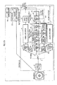
- FIG. 25 shows an internal structure of a reproduction apparatus.
- the reproduction apparatus according to the present invention is industrially manufactured based on this internal structure.
- the reproduction apparatus is roughly made up of three parts that are a system LSI, a drive device, and a microcomputer system.
- the reproduction apparatus can be manufactured by mounting these parts on a cabinet and substrate of the apparatus.
- the system LSI is an integrated circuit including various processing units for achieving the functions of the reproduction apparatus.
- the reproduction apparatus manufactured in the above manner is composed of a BD drive 1, a track buffer 2, a PID filter 3, transport buffers 4a, 4b, and 4c, a peripheral circuit 4d, a video decoder 5, a video plane 6, an audio decoder 7, a graphics plane 8, a CLUT unit 9, an adder 10, and a graphics decoder 12, a coded data buffer 13, a peripheral circuit 13a, a Stream Graphics Processor 14, an object buffer 15, a composition buffer 16, a graphics controller 17, a UO controller 18, a player register group 19, and a controller 20.
- the BD drive 1 performs loading, reading, and ejecting of the BD-ROM so as to access the BD-ROM.
- the track buffer 2 is a FIFO memory. Accordingly, TS packets read from the BD-ROM are removed from the track buffer 2 in the same order as they arrive.
- the PID filter 3 performs filtering on TS packets output from the track buffer 2.
- the PID filter 3 passes only TS packets having predetermined PIDs to the transport buffers 4a, 4b, and 4c. There is no buffering required inside the PID filter 3. Accordingly, TS packets entering the PID filter 3 are written to the transport buffers 4a, 4b, and 4c without delay.
- the transport buffers 4a, 4b, and 4c are FIFO memories for storing TS packets output from the PID filter 3.
- the peripheral circuit 4d has a wired logic for converting TS packets read from the transport buffers 4a, 4b, and 4c to functional segments. The functional segments are then stored to the coded data buffer 13.
- the video decoder 5 decodes TS packets output from the PID filter 3 to obtain uncompressed pictures, and writes the obtained pictures onto the video plane 6.
- the video plane 6 is a plane memory for video data.
- the audio decoder 7 decodes TS packets output from the PID filter 3, and outputs uncompressed audio data.
- the graphics plane 8 is a plane memory having a memory area of one screen, and is capable of storing uncompressed graphics of one screen.
- the CLUT unit 9 converts index colors of the uncompressed graphics on the graphics plane 8, based on Y, Cr, and Cb values defined in a PDS.
- the adder 10 multiplies the uncompressed graphics converted by the CLUT unit 9, by a T value (transparency) defined in the PDS. The adder 10 then performs addition for corresponding pixels in the resulting uncompressed graphics and the uncompressed picture data on the video plane 6 to output a composite image.
- the graphics decoder 12 decodes a graphics stream to obtain uncompressed graphics, and renders the uncompressed graphics to the graphics plane 8 as graphics objects. As a result of decoding the graphics stream, subtitles and menus appear on the screen.
- This graphics decoder 12 is composed of the coded data buffer 13, the peripheral circuit 13a, the stream graphics processor 14, the object buffer 15, the composition buffer 16, and the graphical controller 17.
- the coded data buffer 13 is used for storing functional segments together with their DTSs and PTSs.
- the functional segments are obtained by removing a TS packet header and a PES packet header from each TS packet stored in the transport buffers 4a, 4b, and 4c, and arranging the payloads in sequence.
- the DTSs and PTSs contained in the removed TS packet headers and PES packet headers are stored in correspondence with the PES packets.
- the peripheral circuit 13a has a wired logic for transferring data from the coded data buffer 13 to the stream graphics processor 14, as well as from the coded data buffer 13 to the composition buffer 16.
- the peripheral circuit 13a transfers the ODS from the coded data buffer 13 to the stream graphics processor 14.
- the peripheral circuit 13a transfers the ICS or PDS from the coded data buffer 13 to the composition buffer 16.
- the stream graphics processor 14 decodes an ODS to obtain uncompressed graphics having index colors, and transfers the uncompressed graphics to the object buffer 15 as a graphics object.
- the decoding by the stream graphics processor 14 begins at the time shown by the DTS associated with the ODS and ends by the decoding deadline shown by the PTS also associated with the ODS.
- the decode rate Rd of the graphics object decoding mentioned above is equal to the output rate of the stream graphics processor 14.
- the object buffer 15 stores graphics objects decoded by the stream graphics processor 14.
- the composition buffer 16 is used for storing an ICS and a PDS.
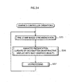
- the graphics controller 17 decodes an ICS stored in the composition buffer 16, and carries out control based on a decoding result at the timing specified by the PTS attached to the ICS.
- the UO controller 18 detects a user operation made on the remote controller and the front panel of reproduction apparatus, and outputs information showing the detected user operation (hereinafter referred to as a UO (User Operations)) to the controller 20.
- a UO User Operations
- the player register group 19 is a group of registers provided within the controller 20, and includes 32 player status registers and 32 general purpose registers.
- the meanings of player status register values (PRS) are shown below.
- the expression "PSR (x) " represents the value of the xth player status register.
- the PSR(8) is updated each time a picture belonging to the AV Clip is displayed. That is, when the reproduction apparatus displays a new picture, the PSR(8) is updated so as to hold the value corresponding to the display start time (i.e. Presentation Time) of the newly displayed picture. With reference to PRS (8), the current reproduction point is known.
- the controller 20 performs integral control through the bi-directional data exchanges with the graphics decoder 12.
- the data outputted from the controller 20 to the graphics decoder 12 is UOs received by the UO controller 18.
- the data outputted from the graphics decoder 12 to the controller 20 is button commands included in an ICS.
- the components of reproduction apparatus having the above structure perform processing in a pipeline.
- FIG. 26 is a timing chart showing decoding of ODSs.
- the forth level shows DSs recorded on the BD-ROM.
- the third level shows the read durations of ICSs, PDSs, and ODSs by the coded data buffer 13.
- the second level shows the decode durations of the ODSs by the stream graphics processor 14.
- the first level shows durations of processing by the graphics controller 17.
- the decoding start time of each ODS is shown in the figure as DTS11, DTS12, and DTS13.
- Each ODS needs to be read to the coded data buffer 13 by the decoding start time specified by a respective DTS. Therefore, the reading of ODS1 is completed, at the latest, immediately before the decode duration dp1 of the ODS1 to the coded data buffer 13. Similarly, the reading of ODS (n) is completed, at the latest, immediately before the decode duration dp2 of the ODS2.
- each ODS is read to the coded data buffer 13 by the time shown by a respective DTS of the ODS, and the read ODS is decoded and loaded to the object buffer 15 by the time shown by a respective PTS of the ODS.
- the above processing is performed in pipeline by the single stream graphics processor 14.
- the duration cd1 is needed for the graphics controller 17 to clear the graphics plane 8
- the duration td1 is needed for rendering the graphics on the object buffer 15 to the graphics plane 8.
- the position within the graphics plane 8 for rendering is specified by the button_horizontal_position and button_vertical_position fields in the ICS. That is to say, uncompressed graphics constituting an interactive display is obtained on the graphics plane 8 at the end of time calculated by adding to the PTS13 value of the ODS, the plane clear duration cd1 and the rendering duration td1 of the decoded graphics objects.
- the CLUT unit 9 performs color conversion on the uncompressed graphics, and the adder 10 overlays the graphics on an uncompressed picture stored with the video plane 6. As a result, a composite image is produced.
- the initial interactive display is presented without waiting for completion of the decoding of the ODSs belonging to the button-state groups for the selected state and the activated state.
- the presentation is earlier by the duration hy1 shown in the figure.
- the stream graphics processor 14 continues decoding while the graphics controller 17 is clearing or rendering the graphics plane 8 (the decode durations of ODS (n), ODS 1, ODS (n) shown on the second level) . Since the decoding of the remaining ODSs are continued even during the graphics controller 17 is clearing or rendering the graphics plane 8, the decoding of the remaining ODSs are completed earlier than would otherwise be the case. Thus, updates of the interactive display using those remaining ODSs can be carried out immediately upon a user operation. As a result of such pipeline processing, presentation of the initial interactive display and updates to the display can be carried out speedily.
- FIG. 26 relates to the case where a default selected button is specified.
- FIG. 27 is a timing chart showing the pipeline processing performed by the reproduction apparatus in the case where no default selected button is specified.
- all of the graphics objects needed for presentation the initial display become available upon completion of decoding all the ODSs for the normal state and for the selected state, and loading the resulting objects to the graphics plane 8.
- the initial interactive display is presented without waiting for completion of the decoding of the ODSs for the activated state.
- the presentation is earlier by the duration hy2 shown in the figure.
- the controller 20 can be implemented by a general-purpose CPU executing a program of the steps shown by FIGs. 28 and 29 .
- a description is given to operations performed by the controller 20 with reference to FIGS. 28 and 29 .
- FIG. 28 is a flowchart of the operations performed by the controller 20 for executing a LinkPL function. Upon decoding a command including a LinkPL function, the controller 20 operates as shown in FIG. 20 .
- the PlayItem and Access Unit to be processed are denoted as PI (y) and Access Unit (v), respectively.
- the reproduction apparatus reads the PL (.mpls) specified by the argument of the LinkPL (step S1), and designates the first PI in the current PL as a PI (y) (step S2).
- the reproduction apparatus then reads Clip information specified by the Clip_information_file_name field in the PI (y) (step S3).
- the reproduction apparatus Upon reading the Clip information, the reproduction apparatus converts the value of IN_time field within the PI (y) to an address using the EP_map included in the Clip information (step S4).
- the Access Unit specified by the resulting address is designated as an Access Unit (v) (step S5).
- the reproduction apparatus also converts the value of Out_time field to the address using the EP_map included in the Clip information (step S6).
- the Access Unit specified by the resulting address is designated as an Access Unit (w) (step S7).
- the reproduction apparatus instructs the BD drive to read the Access Units from (v) through (w) (step S8), and also instructs the video decoder 5, the audio decoder 7, the graphics decoder 12 to decode the data residing at the addresses corresponding to the In_time through Out_time fields of the PI (y) (step S9).
- step S11 an end judgment of this flowchart is made to see if the PI (y) is equal to PI (z) . If the step S11 results in "YES”, the processing of this flowchart is terminated. If not, the next PlayItem is designated as a new PI (y) (step S12), and the processing goes back to the step S3. The steps S1-S10 are repeated until the step S11 results in "YES".
- a function segment is loaded to the coded data buffer 13 simultaneously with the reading of Access Units.
- FIG. 29 is a flowchart of the operations preformed for loading functional segments.
- a Segment (K) is a variable indicating a segment (ICS, ODS, or PDS) read with an Access Unit, and an ignore flag indicates whether the Segment (K) is to be ignored or loaded.
- the ignore flag is initialized to 0 (step S20)
- a loop of steps S21 to S24 and S27 to S35 is performed for the Segment (K) (S25 and S26).
- the reproduction apparatus judges whether the Segment (K) is an ICS. If the Segment (K) is an ICS, the processing goes to the judgments in the steps S27 and S28.
- step S27 a judgment is made as to whether the segment_type field within the ICS is set to a value indicating an Acquisition Point DS. If the Segment (K) belongs to an Acquisition Point DS, the processing goes to the step S28. On the other hand, if the Segment (K) belongs to either an Epoch Start or Normal Case DS, the processing goes to the step S33.
- step S28 a judgment is made as to whether the immediately preceding DS is stored in the coded data buffer 13.
- the step S28 is performed if the step S27 results in "YES".
- the immediately preceding DS is not stored in the coded data buffer 13 if a skip operation is performed. In this case, the presentation needs to be started from an Acquisition Point DS, so that the processing goes to the step S30 (S28: NO).
- step S28 the ignore flag is set to "1" (step S29), and the processing goes to the step S31.
- step S31 a judgment is made as to whether the command_update_flag field is set to "1". If set to "1" (step S31: YES), the button command of the button information is loaded to the coded data buffer 13 while the other data is ignored (step S32) . If the command_update_flag field is set to "0", the processing goes to the step S22. Consequently, the ICS indicating an Acquisition Point is ignored (step S24) .
- step S22 results in "NO", so that all the functional segments belonging to an Acquisition Point DS is ignored.
- Step S22 If the ignore flag is set to "0" (Step S22: YES), the Segment (K) is loaded to the coded data buffer 13 (step S23) .
- the processing goes to the step S34.
- a judgment is made as to whether the immediately preceding DS is stored in the coded data buffer 13. If the immediately preceding DS is stored, the ignore flag is set to "0" (step S30). If not, the ignore flag is set to "1" (step S35). With the ignore flag set as above, the functional segments belonging to a Normal Case DS are ignored if the immediately preceding DS is not stored in the coded data buffer 13 of the reproduction apparatus.
- buttons go into the activated stated instead of the selected state, and the button commands (LinkPL(PL#21), LinkPL(PL#22), and LinkPL(PL#23)) within the pieces of button information are executed.
- the button commands (LinkPL(PL#21), LinkPL(PL#22), and LinkPL(PL#23)) within the pieces of button information are executed.
- PL#21, PL#22, and PL#23 to which the button commands are linked are butting and pitching scenes of baseball players, those scenes are reproduced upon a numeric input of a corresponding player number. Since the selection is made with an input of a player number, which is easy to recognize for users, the user operability is further enhanced.
- DSs are multiplexed with video data.
- the segment_type field shows Epoch Start
- the command_update_flag field is set to "0”
- the button command LinkPL(PL#5) is included.
- the DS 10 is a duplicate of the DS1.
- the segment_type field is set to a value indicating an Acquisition Point DS
- the command_update_flag is set to "0”
- the button command LinkPL(PL#5) is included.
- the DS20 is inherited from the DS1 and its segment_type field value indicates an Acquisition Point DS.
- the DS20 differs from the DS1 in the button command (LinkPL(PL#10)), so that the command_update_flag is set to "1" to signal that the button command is different.
- a skip operation is made to a picture pt10 in the AV Clip in which the above three DSs are multiplexed with video data.
- the DS10 which is closest to the skip destination point is subjected to the processing shown in FIG. 29 .
- the judgment in the step S27 results in that the segment_type is an Acquisition Point DS, but the immediately preceding DS is not stored in the coded data buffer 13. Accordingly, the ignore flag is set to 0.
- the DS10 is loaded to the coded data buffer 13 as shown in FIG. 31 .
- a skip operation is made to a picture which is located at a later point than the DS10 (arrow hst1 in FIG. 30 ).
- the DS20 which follows the DS10 is loaded to the coded data buffer 13 (arrow hst2 in FIG. 31 )).
- FIG. 33 shows how the DS1, DS10, and DS20 are loaded when normal reproduction is performed as shown in FIG. 32 .
- the DS1 of which segment_type field shows an Epoch Start DS is loaded to the coded data buffer 13 (step S23).
- the ignore flag is set to "1" (step S29). Consequently, the functional segments of DS10 are not loaded to the coded data buffer 13 but ignored (step S24).
- the segment_type field shows an Acquisition Point DS, but the command_update_flag is set to "1".
- the step 31 results in "YES”. Consequently, the button command is loaded to the coded data Buffer 13, thereby replacing the currently stored button command within the ICS of the DS.
- the ignore flag is set to "1", and thus other data than the button command is not loaded but ignored.
- FIG. 34 shows the main routine of the processing performed by the graphics controller 17.
- the flowchart shows that the following three operations are repeated: time stamp synchronization (step S35); animation presentation (step S36); and UO processing (step S37).
- FIG. 35 is a flowchart of the synchronization control carried out based on the time stamps.
- judgments are made in the step S43-S47 as to whether specific events have occurred.
- An occurrence of each event calls a respective subroutine which retunes to the main routine after predetermined steps are performed.
- step S43 a judgment is made as to whether the current reproduction point has reached the time shown by the PTS of the ODS. If judged in the affirmative, the rendering to the graphics plane 8 is performed (step S51), and then the processing goes back to the main routine.
- step S45 a judgment is made as to whether the current reproduction point has reached the PTS of the ICS. If judged in the affirmative, the graphics plane 8 is started to output the stored content. The output is made to the CLUT unit 9 where color conversion is made. After the color conversion, the interactive compotation is overlaid with the content stored in the video plane 6, thereby an initial interactive display is presented (step S52). Then, a variable q is set to the value "1" (step S53), and the processing returns to the main routine. Note that the variable q is a global variable (i.e. variable valid throughout a plurality of flowcharts) and its meaning is described later.
- step S46 the judgment is made as to whether the current reproduction point has reached the time shown by the selection_time_out_pts. If the judgment results in the affirmative, the button specified by the default_activated_button_number is activated, and then the processing goes back to the main routine (step S54).
- step S47 the judgment is made as to whether the current reproduction point has reached the time specified by the composition_time_out_pts. If the judgment results in the affirmative, the processing retunes to the main routine after clearing the graphics plane (step S55). This concludes the description of the synchronization based on the time stamps.
- the steps 51 and 54 call subroutines. The subroutine of the step S51 is described below with reference to FIG. 36 .
- FIG. 36 is a flowchart of the rendering to the graphics plane 8.
- the rendering to the graphics plane 8 needs to be completed before the presentation of initial interactive display.
- the ODSx represents the ODS having the PTS corresponding to the current reproduction point, which is shown by the PRS (10).
- steps S61-563 judgments are made as to whether the ODS is the last one of the ODSs necessary for the initial interactive display. If the ODS is the last one, the steps S64-S72 are performed.
- step S61 a judgment is made as to whether the default_selected_button number field has a valid value. If it is valid, a judgment is made in the step S63 as to whether ODSx is S-ODSsfirst. If the step S63 results in "NO", the processing of this flowchart is terminated and returns to the main routine.
- step S61 results in "NO"
- step S62 a judgment is made in the step S62 as to whether the ODSx is S-ODSslast. If the step S62 results in "NO”, the processing of this flowchart is terminated and returns to the main routine.
- step S64 a judgment is made as to whether the segment_type field within the ICS shows an Epoch Start DS. If an Epoch Start DS is shown, the step S65 is performed to clear the graphics plane 8, and the steps S66-72 are performed. The duration taken for clearing the graphics plane 8 is the duration cd1 shown in FIGs. 23 and 24 . If the segment_type field does not show an Epoch Start DS, the step S65 is skipped to the steps S66-72.
- the steps S66-S72 form a loop in which each piece of button information in the ICS is sequentially processed (steps S66 and S67).
- the current piece of button information to be processed is denoted as button_info (p).
- the step S68 a judgment is made as to whether the button_info (p) corresponds to a default selected button specified by the default_selected_button_number.
- buttons_info (p) does not corresponding to the default selected button, out of the graphics objects stored in the object buffer 15, the one specified in the start_object_id_normal field of the button_info(p) is designated as the graphics object(p)(step S69).
- the button_info (p) corresponds to the default selected button, out of the graphics objects stored in the object buffer 15, the one specified by the start_object_id_selected field of the button_info (p) is designated as the graphics object (p) (step S70). Then, the button (p) is designated as the current button (step S71).
- the current button refers to the one having the selected state in the currently presented interactive display.
- the reproduction apparatus stores the ID of the current button in the PRS(10).
- the graphics object (p) is designated through the steps S69 and S70, the graphics object (p) is rendered onto the graphics plane 8 at the position shown by the button_horizontal_position and button_vertical_position fields (step S72).
- the above processing is repeated for each piece of button information within the ICS.
- the first graphics object is rendered for each button on the graphics plane 8.
- the duration taken for rendering all the graphics object stored in the object buffer 15 is the duration td1 shown in FIGs. 23 and 24 . This concludes the description of the step S51.
- a description is given to the subroutine called in the step S54.
- FIG. 37 is a flowchart of the processing for automatic activation of the default selected button.
- a judgment is made as to whether the default_activated_button_number field is set to "00" or "FF" (step S91). If the field is set to "00”, the processing returns to the main routine without performing any operation. On the other hand, if the default_activated_button_number is set to "FF", the current button is designated as the button (u) (step S95).
- the button specified by the default_activated_button_number field is designated as the button (u) (step S92) and activates the button (u) (step S93).
- This button state transition is carried out by rendering the sequence of graphics objects from the one specified by the start_object_id_activated field and to the one specified by the end_object_id_activated field in the button_info (u).
- the rendering position on the graphics plane 8 is shown by the button_horizontal_position and button_vertical_position fields. Then, the button command associated with the button (u) is executed (step S94), and the processing returns to the main routine.
- the button in the selected state goes into the activated state at the end of a predetermined duration. This concludes the description of the flowchart shown in FIG. 37 .
- FIG. 38 is a flowchart of the processing for animated presentation.
- the initial display has been presented by rendering onto the graphics plane 8, the graphics objects specified in the start_object_id_normal and start_object_id_selected fields of each piece of button_info.
- the graphics plane 8 is updated by overwriting each button with an arbitrary frame (the (q)th graphics object) of the button.
- the update is made to the graphics plane 8 by sequentially rendering the graphics objects specified by the normal_state_info and selected_state_info in each piece of button_info.
- the variable q is used to refer to an individual graphics object specified in the normal_state_info and selected_state_info fields in each piece of button information.
- step S83 a judgment is made as to whether the button_info (p) corresponds to the current button.
- the variable q is added to the value of start_object_id_normal in the button_info (p) to obtain an ID(q) (step S84).
- buttons_info (p) corresponds to the current button
- the variable q is added to the value of start_object_id_selected field in the button_info(p) to obtain an ID(q) (step S85).
- the graphics object (q) is rendered onto the graphics plane 8 at the position specified by the button_horizontal_position and the button_vertical_position fields of the button_info (p) (step S87).
- the above operations are repeated for every piece of button_info within the ICS (steps S81 and S82).
- the (q) th graphics objects are rendered on the graphics plane 8 for each button.
- step S88 a judgment is made as to whether the value of the end_object_ id_normal field has reached the value obtained by the start_object_id_normal field + q (step S89). If judged in the affirmative, the variable q is initialized to "0" and the processing returns to the main routine (step S89). If judged in the negative, the variable q is incremented by 1, and the processing returns to the main routine (step S90).
- each button on the interactive display is updated using a new graphics obj ect each time the loop of steps S35-S37 is executed.
- each button is presented in animation.
- the graphics controller 17 makes the adjustment so as to present the graphics objects at the rate shown by the animation_frame_rate_code. Such adjustment is made also in the other flowcharts when applicable. This concludes the description of processing for animated presentation.
- a description is given to the UO processing shown in the step S37 of the main routine, with reference to FIG. 39 .
- FIG. 39 is a flowchart of the UO processing.
- judgments are made in steps S100-S103 as to whether specific events have occurred. An occurrence of each event calls a respective subroutine which returns to the main routine after predetermined steps are performed.
- a judgment is made as to whether the UO_mask_table field is set to "1". If the filed is set to "1", the processing returns to the main routine without performing any operation. .
- step S101 the judgment is made as to whether any of the Move Up, Down, Left, and Right keys is pushed.
- another button is designated as the current button accordingly (step S104), followed by the judgment as to whether the auto_action_flag of the newly designated current button is set to "01" (step S108). If the auto_action_flag is not set to "01”, the processing returns to the main routine. On the other hand, if the auto_action_flag is set to "01", the processing goes onto the step S105.
- step S102 a judgment is made as to whether the Activate key is pushed.
- the current button is activated in the step S105.
- This button state transition is carried out by rendering onto the graphics plane 8 the sequence of graphics objects from the one specified by the start_object_id_activated field and the one specified by the end_object_id_activated field of the current button.
- the rendering position in the graphics plane 8 is specified by the button_horizontal_position and the button_vertical_position fields of the current button.
- the steps S104 and S107 each call a subroutine.
- FIGs. 40 and 41 show the subroutines. Now, a description is given to those flowcharts.
- FIG. 40 is a flowchart of the current button change processing. The flowchart is described on the precondition that animation of every button is presented with the same number of frames. This is for the sake of simplicity in the description. The presentation of buttons with different numbers of frames requires more complex processing. First, it is determined which of upper_button_number, lower_button_number, left_button_number, and right_button_number in the neighbor_info of the current button corresponds to the pushed key (step S110).
- buttons S111 Let the button (i) denote the current button and the button (j) denote the button to be designated next as the current button (step S111).
- a judgment is made as to whether the button (j) designated in the step S111 is equal to the button (i). If so, the processing returns to the main routine without performing any operation. If not, steps S113-S120 are performed.
- the button (j) is put into the selected state and the button (i) is put back to the normal state.
- Each button state is presented in animation.
- a variable r is first initialized to "0" .
- the variable r is used to refer to an individual frame of the animation.
- the (r)th one of the graphics objects associated with the button (i) in the normal state and the (r)th one of the graphics objects associated with the button (j) in the selected state is repeatedly rendered onto the graphics plane.
- the ID(r) is calculated by adding the variable r to the value of the start_object_id_normal field of button info (i) (step S114) .
- the one having the ID(r) is rendered onto the graphics plane 8 at the position shown in the button_horizontal_position and button_vertical_position fields of the button_info(i) (step S115).
- the ID (r) is then calculated by adding the variable r to the value of the start_object_id_selected field of the button info (j) (step S116).
- the one having the ID(r) is rendered onto the graphics plane 8 at the position shown in the button_horizontal_position and button_vertical_position fields of the button_info(j) (step S117).
- step S118 a judgment is made as to whether the ID obtained by adding the variable r to the value of start_object_id_normal field is equal to the value of end_object_id_normal field. If the values are not equal, the variable r is incremented (step S120), and the processing goes back to the step S114. The steps S114-S120 are repeated until the judgment in the step S118 results in "YES". By repeating the above steps, the button state transition is achieved such that characters serving as buttons make motion in response to a user operation. When the judgment in the step S118 results in "YES", the button (j) is now designated as the current button (step S119) and the processing returns to the main routine.
- FIG. 41 is a flowchart of the numeric input processing.
- a judgment is made as to whether there is a piece of button_info (j) having the button_number matching the inputted numeral (step S121).
- a judgment is made as to whether the numerically_selectable_flag field in the button_info (j) is set to "1" (step S122). If both the steps S121 and S122 result in "YES”, a judgment is made as to whether the auto_action_flag field in the button_info (j) is set to "01" (step S123).
- the sequence of graphics objects from the one specified by the start_object_id_selected field to one specified by the end object_ id_ selected field associated with the button (j) is sequentially rendered at the position specified by the button_horizontal_position and button_vertical_position fields associated with the button (j) (step S124).
- the button (j) is put into the selected state.
- the button (j) is designated as the current button (step S125), and the processing returns to the main routine.
- the current button is activated in the step S126.
- This button state transition is carried out by sequentially rendering the sequence of graphics objects from the one specified by the start_object_id_activated field to the one specified by the end_object_id_activated field associated with the current button onto the graphics plane 8 at the position specified by the button_horizontal_position and button_vertical_position fields associated with the current button.
- the button command associated with the button (j) is executed, and the processing returns to the main routine.
- the stream graphics processor 14 and the graphics controller 17 perform the following operations, which are similar to those performed for synchronous display.
- the graphics plane 8 obtains necessary graphics objects. After obtaining the graphics objects, no operation is performed until the current reproduction point reaches the time specified by the PTS attached to the ICS. If the UO controller 18 receives a user operation of a menu call after the current reproduction point has passed the time specified by the PTS, the graphics objects stored in the graphics plane 8 are outputted to the CLUT unit 9 where the outputted graphics objects are overlaid with the video plane. The output performed in synchronization with the UO leads to presentation of the Popup display in response to the menu call.
- Epochs each composed of an ICS and ODSs are multiplexed in an AV Clip.
- an AV Clip interactive control is readily described such that the reproduction apparatus performs a specific operation in synchronization with the presentation of a specific frame of the video.
- the AV Clip of the present invention is suitable for describing interactive control closely bound to the presentation timing of video frames.
- Epochs are multiplexed within the AV Clip, even when reproduction of hundreds of video segments is requested, it is not necessary to store all the related Epochs to the memory. Epochs are sequentially read from the BD-ROM with video packets.
- the ICS associated with the video segment currently reproduced stays resident in the memory throughout the duration of that video segment.
- the Epoch having been reproduced is removed from the memory and an ICS corresponding to the next video segment is then loaded to the memory. Since the Epochs are multiplexed in the AV Clip, the required size of memory is kept to a minimum even if the number of Epochs exceeds several hundreds.
- a second embodiment of the present invention relates to the improvement on a click sound reproduced at the time when the button state is changed to the selected state and the activated stated.
- a user interact with the characters appearing in the movie serve as buttons as shown in FIGS. 16 and 17 .
- the voice of a respective character is reproduced as a click sound in response to the user operations, the user can instinctively recognize which of the buttons the user is operating.
- the main sound used herein refers to the sound of the movie, such as the speech of the characters and background music in the movie.
- the audio stream carrying the main sound is multiplexed into the AV Clip with the video and graphics streams.
- the audio decoder 7 decodes the audio stream.
- the main audio needs to be muted.
- the operations of audio decoder 7 need to be suspended.
- the suspension of audio decoder 7 involves the risk of producing noise.
- the reproduction apparatus has the internal structure as shown in FIG. 42 .
- the structure shown in this figure is similar to the one shown in the FIG. 25 with the addition of a preload memory 21 and a mixer 22.
- the preload memory 21 stores in advance uncompressed LPCM data to be reproduced as s click sound.
- the mixer 22 mixes the uncompressed LPCM data stored in the preload memory 21 with the output of the audio decoder 7.
- the data is mixed at the rate instructed by the graphics controller 17 included in the graphics decoder 12 (see FIG. 25 ). Since a click sound is reproduced in accordance with the mixing parameters, it is not necessary to suspend the output of audio decoder 7.
- the decompressed LPCM data recorded on the BD-ROM needs to be loaded to the preload memory 21 in advance.
- the size of decompressed LPCM data is relatively large. For example, less than ten seconds of 16-bit/48 kHz LPCM audio data has the size of one megabyte.
- the ICS according to the present invention has the data structure as shown in FIG. 43.
- FIG 43 shows the data structure of ICS for reproducing the click sound in the above manner.
- the data structure in the figure differs from the one shown in FIG. 11 in the button_info.
- the selected_state_info() and the activated_state_info() each additionally have "audio_specification_info” field and "audio_reproduction_control_info” field.
- the audio_specification_info field shows a file name or ID of audio data to be read and reproduced as a click sound by the reproduction apparatus when the button associated with the button_info is put into a different state.
- the click sound data to be loaded to the preload memory 21 is specified by the selected_state_info() and activated_state_info() of the button_info.
- the click sound data loaded to the preload memory is supplied to the mixer 22.
- the audio_reproduction_control_info is composed of a plurality of mixing parameters. Each mixing parameter shows the rate at which each audio component is to be mixed with the main sound. Each mixing parameters takes on a value within a range of 0-1.0. The click sound data is multiplied by the values shown by the mixing parameters before being reproduced.
- the audio_reproduction_control_info field shows separate mixing parameters for R and L components, so that the mixer 22 is instructed to mix the audio data at the mixing rates shown by those parameters.
- the L component of the uncompressed LPCM data may represent the click sound of button A, while the R component representing the click sound of button B. In this way, two different click sounds for two different buttons may be collectively stored as one piece of uncompressed LPCM data.
- the button_info (1) includes the audio_reproduction_control_info set for output of the R component only
- the button_info(2) includes the audio_reproduction_control_info set for output of the L components only.
- the R component of uncompressed LPCM data is reproduced according to the audio_reproduction_control_info of the button_info(2), so that the click sound of button B is reproduced.
- the state control information shown in FIG. 44A includes button_info (1) and button_info(2). As shown by the arrows sy1 and sy2 in the figure, both the button_info (1) and button_info 2) specify the same piece of click sound data, which is stereo sound.
- the audio_reproduction_control_info of the button_info (1) includes the mixing parameter for L component
- the audio_reproduction_control_info of the button_info(2) includes the mixing parameter for R component.
- FIG. 44B shows the reading process of the ICS including the state control information. Prior to the ICS, click sound data is loaded to the preload memory 21.
- FIGs. 45A and 45B illustrate the reproduction control of the click sound data according to the ICS read to the preload memory 21.
- the graphics decoder 12 controls the audio decoder 7 so that the click sound data is reproduced according to the audio_reproduction_control_info of the button_info (1).
- the L component of the stereo click sound data is reproduced.
- the graphics decoder 12 controls the audio decoder 7 so that the click sound data is reproduced according to the audio_reproduction_control_info of the button_info(2).
- the R component of the stereo click sound data is reproduced.
- a piece of click sound data composed in stereo is used as the click sound of button A by reproducing the L component and as the click sound of button B by reproducing the R component, when a respective button is selected.
- buttons_info of the present invention may be set so as to produce the click sound upon a button operation in a manner that the sound comes from a different direction.
- FIG. 45C shows an example of three pieces of button_info associated with three laterally aligned buttons (button A, button B, and button C).
- the button_info associated with the button A which is on the left, has the mixing parameter of 1.0 for the L component.
- the button_info associated with the button B which is in the middle, has the mixing parameters of 0.5 for both the L and R components.
- the button info associated with the button C which is on the right, has the mixing parameter of 1.0 for the R component.
- the button_info may be set so that the click sound is outputted from a different direction depending on the position of button on the screen. The click sound coming from the direction corresponding to the position of the button pushed adds to the realism in the button operations.
- a click sound for each of a plurality of buttons is integrated into one piece of stereo click sound data.
- audio_specification_info and audio_reproduction_control_info the same piece of click sound data is reproduced as different click sounds for different buttons.
- the amount of click sound data is reduced, and thus the size of preload memory 21 for loading the click sound data can be reduced.
- the click sound data may be uncompressed 5.2-channel audio data.
- FIG. 44C shows an example similar to the one shown in FIG. 45C .
- the mixing parameters are set for reproduction of 5.2-channel audio data.
- the 5. 2-channel audio data includes Center, Rear Left, and Rear Right components.
- the buttons A, B, and C are diagonally aligned on the interactive display.
- the button_info associated with the button A has the mixing parameter of 1.0 for L component.
- the button_info associated with the button C has the mixing parameter of 1.0 for Rear Right component.
- the button_info associated with the button B has the mixing parameters of 0.1, 0.1, 0.4, 0.2, and 0.2 for L, R, Center, Rear Left, Rear Right components, respectively.
- the button A when the button A is selected, the click sound is outputted from the right.
- the button B When the button B is selected, the click sound is outputted from the left.
- the middle button B When the middle button B is selected, the click sound is outputted from all the directions. As above, the direction from which the click sound comes is changed depending on the position of the button pushed.
- This arrangement adds to the realism in button operations (Note in the above example, the button_info associated with the button B may alternatively be set to have the parameter of 1.0 for the Center component and the parameter of 1.0 for each of the other components).
- another audio decoder may be provided for click sound data.
- the preload memory 21 stores compressed audio data in advance.
- the audio decoder for click sound data extracts the compressed audio data from the preload memory 21 and decodes the extracted data.
- the provision of the audio decoder for click sound data allows the preload memory 21 to store the compressed audio data, so that the size of preload memory 21 can be reduced.
- FIG. 46 is a flowchart of the manufacturing process of the BD-ROM according to the present invention.
- the manufacturing process includes a material production step of recording video, sound, and the like (step S201), an authoring step of creating an application format using an authoring device (step S202), and a pressing step of creating an original master of the BD-ROM and performing stamping and bonding to complete the BD-ROM (step S203) .
- the BD-ROM authoring step includes the following steps S204-S209.
- step S240 videomaterials, audiomaterials, and supplemental graphics materials are encoded into a video stream, an audio stream, and a graphics stream, respectively.
- step S205 the verification test of the graphics stream is carried out.
- the graphics stream includes, in addition to graphics data for presentation of buttons, state control information of the button. This makes it possible to verify the graphics stream independently. If any error is detected (step S206: NO), an appropriate correction is made to the graphics stream, which is not yet multiplexed with the other streams (step S207), and the verification test of the graphics streams is carried out again.
- step S206 If no error is detected through the verification test of graphics stream (step S206 : YES), the video, audio, graphics streams, which are obtained in the step S208 by encoding the materials, are interleaved multiplex converted to one digital stream.
- step S209 necessary information is generated based on the scenario for the BD-ROM, and the scenario and digital stream are adapted to be in compliance with the BD-ROM format.
- the ICS defining the button state transition is integrated into the graphics stream with graphics data.
- the graphic stream is ready for verification test upon its production to see how the button states change as the reproduction proceeds. Since the verification test of button state transition can be carried out at an earlier stage of authoring, a possibility is avoided that an error is detected right before the shipment, which forces the developers to rush.
- the verification test of graphic stream alone provides a better environment for incorporating animated buttons of complex motion into a movie.
- a recording medium and a reproduction apparatus realize interactive control on a movie, thereby adding value to the movie. Movies distributed with such added value invigorate the movie market and consumer appliance market. Thus, the recording medium and the reproduction apparatus according to the present invention are highly applicable in the movie and the consumer appliance industries.
Claims (5)
- Aufzeichnungsmedium (100), das umfasst:einen digitalen Strom, zu dem ein Video-Strom und ein Grafik-Strom multiplexiert werden, wobeider Grafik-Strom Grafik-Daten (ODS) und Status-Steuerinformationen (ICS) enthält, die in diesen integriert sind, die Grafik-Daten (ODS) verwendet werden, um eine interaktive Anzeige zusammenzustellen, die wenigstens eine Schaltfläche aufweist, und die Status-Steuerinformationen (ICS) Informationen (selection_time_out_pts), die eine Auswahlperioden-Beendigungszeit der Schaltfläche beschreiben, sowie Informationen ((button_info(i)) aufweisen, die die Schaltfläche definieren, um die interaktive Anzeige zu veranlassen, in Reaktion auf einen Wiedergabevorgang des Video-Stroms und eine Benutzerbetätigung der Schaltfläche in einen anderen Zustand überzugehen;der Grafik-Strom ein Paket-String ist;der Paket-String wenigstens einen Satz von Paketen (Display Set) enthält, wobei jeder Satz von Paketen ein Paket, das Status-Steuerinformationen (ICS) beinhaltet, und wenigstens ein Paket enthält, das Grafik-Daten (ODS) beinhaltet; undan das Paket, das Status-Steuerinformationen (ICS) beinhaltet, ein Zeitstempel angehängt ist, der eine Anzeigezeit eines in Synchronisation mit der interaktiven Anzeige anzuzeigenden Bildes angibt.
- Wiedergabevorrichtung (200) zum Wiedergeben eines digitalen Stroms, zu dem ein Video-Strom und ein Grafik-Strom multiplexiert sind, wobei die Wiedergabevorrichtung (200) umfasst:einen Video-Decoder (5), der so betrieben werden kann, dass er den Video-Strom decodiert, um Video-Daten zu gewinnen; undeinen Grafik-Decoder (12), der so betrieben werden kann, dass er den Grafik-Strom decodiert, um eine interaktive Anzeige zu erzeugen, die wenigstens eine Schaltfläche aufweist, wobei:der Grafik-Strom Grafik-Daten (ODS) und Status-Steuerinformationen (ICS) enthält;die Status-Steuerinformationen (ICS) Informationen (selection_time_out_pts), die eine Auswahlperioden-Beendigungszeit der Schaltfläche beschreiben, sowie Informationen ((button_info(i)) aufweisen, die die Schaltfläche definieren, um die interaktive Anzeige zu veranlassen, in Reaktion auf einen Wiedergabevorgang der Video-Daten und eine Benutzerbetätigung der Schaltfläche in einen anderen Zustand überzugehen; undder Grafik-Decoder (12) eine Verarbeitungseinheit (14), die so betrieben werden kann, dass sie die in dem Grafik-Strom enthaltenen Grafik-Daten (ODS) decodiert, um die interaktive Anzeige zu erzeugen, und eine Steuereinrichtung (20) enthält, die so betrieben werden kann, dass sie einen Zustand der interaktiven Anzeige auf Basis der Status-Steuerinformationen (ICS) steuert;der Grafik-Strom ein Paket-String ist;der Paket-String wenigstens einen Satz von Paketen (Display Set) enthält, wobei jeder Satz von Paketen ein Paket, das Status-Steuerinformationen (ICS) beinhaltet, und wenigstens ein Paket enthält, das Grafik-Daten (ODS) beinhaltet; undan das Paket, das Status-Steuerinformationen (ICS) beinhaltet, ein Zeitstempel angehängt ist, der eine Anzeigezeit eines in Synchronisation mit der interaktiven Anzeige anzuzeigenden Bildes angibt; unddas Decodieren durch die Verarbeitungseinheit (14) und die Steuerung durch die Steuereinrichtung (20) unter Bezugnahme auf den Zeitstempel durchgeführt werden, der an das Paket angehängt ist, das Zustands-Steuerinformationen (ICS) beinhaltet.
- Verfahren zum Aufzeichnen von Daten auf ein Aufzeichnungsmedium (20), wobei das Verfahren die folgenden Schritte umfasst:Erzeugen von Anwendungsdaten; undAufzeichnen der Anwendungsdaten auf das Aufzeichnungsmedium (100), wobei:die Anwendungsdaten einen digitalen Strom enthalten, zu dem ein Video-Strom und ein Grafik-Strom multiplexiert sind; undder Grafik-Strom Grafik-Daten (ODS) und Status-Steuerinformationen (ICS) enthält, die in diesen integriert sind, wobei die Grafik-Daten (ODS) verwendet werden, um eine interaktive Anzeige zusammenzustellen, die wenigstens eine Schaltfläche aufweist, und die Status-Steuerinformationen (ICS) Informationen (selection_time_out_pts), die eine Auswahlperioden-Beendigungszeit der Schaltfläche beschreiben, sowie Informationen ((button_info(i)) aufweisen, die die Schaltfläche definieren, um die interaktive Anzeige zu veranlassen, in Reaktion auf einen Wiedergabevorgang des Video-Stroms und eine Benutzerbetätigung der Schaltfläche in einen anderen Zustand überzugehen; wobeider Grafik-Strom ein Paket-String ist;der Paket-String wenigstens einen Satz von Paketen (Display Set) enthält, wobei jeder Satz von Paketen ein Paket, das Status-Steuerinformationen (ICS) enthält, und wenigstens ein Paket enthält, das Grafik-Daten (ODS) beinhaltet; undan das Paket, das Status-Steuerinformationen (ICS) beinhaltet, ein Zeitstempel angehängt ist, der eine Anzeigezeit eines in Synchronisation mit der interaktiven Anzeige anzuzeigenden Bildes angibt.
- Programm, mit dem ein Computer befähigt wird, einen digitalen Strom wiederzugeben, zu dem ein Video-Strom und ein Grafik-Strom multiplexiert sind, wobei das Programm Code umfasst, der den Computer veranlasst, die folgenden Vorgänge durchzuführen:Decodieren des Video-Stroms, um Video-Daten zu erzeugen; undDecodieren des Grafik-Stroms, um eine interaktive Anzeige zu erzeugen, die wenigstens eine Schaltfläche aufweist, wobei:der Grafik-Strom Grafik-Daten (ODS) und Status-Steuerinformationen (ICS) enthält;die Status-Steuerinformationen (ICS) Informationen (selection_time_out_pts), die eine Auswahlperioden-Beendigungszeit der Schaltfläche beschreiben, sowie Informationen ((button_info(i)) aufweisen, die die Schaltfläche definieren, um die interaktive Anzeige zu veranlassen, in Reaktion auf einen Wiedergabevorgang des Video-Stroms und eine Benutzerbetätigung der Schaltfläche in einen anderen Zustand überzugehen; unddas Decodieren des Grafik-Stroms (ODS) Decodieren der Grafik-Daten (ODS), die in dem Grafik-Strom enthalten sind, um die interaktive Anzeige zu erzeugen, und Steuern eines Zustandes der interaktiven Anzeige entsprechend den Zustands-Steuerinformationen (ICS) einschließt, wobei:der Grafik-Strom ein Paket-String ist;der Paket-String wenigstens einen Satz von Paketen (Display Set) enthält, wobei jeder Satz von Paketen ein Paket das Status-Steuerinformationen (ICS) beinhaltet, und wenigstens ein Paket enthält, das Grafik-Daten (ODS) beinhaltet; undan das Paket, das Status-Steuerinformationen (ICS) beinhaltet, ein Zeitstempel angehängt ist, der eine Anzeigezeit eines in Synchronisation mit der interaktiven Anzeige anzuzeigenden Bildes angibt; unddas Decodieren durch die Verarbeitungseinheit (14) und die Steuerung durch die Steuereinrichtung (20) unter Bezugnahme auf den Zeitstempel durchgeführt werden, der an das Paket angehängt ist, das Zustands-Steuerinformationen (ICS) beinhaltet.
- Verfahren zum Wiedergeben eines digitalen Stroms, zu dem ein Video-Strom und ein Grafik-Strom multiplexiert werden, wobei das Verfahren die folgenden Schritte umfasst:Decodieren des Video-Stroms, um Video-Daten zu erzeugen; undDecodieren des Grafik-Stroms, um eine interaktive Anzeige zu erzeugen, die wenigstens eine Schaltfläche aufweist, wobei:der Grafik-Strom Grafik-Daten (ODS) und Status-Steuerinformationen (ICS) enthält;die Status-Steuerinformationen (ICS) Informationen (selection_time_out_pts), die eine Auswahlperioden-Beendigungszeit der Schaltfläche beschreiben, sowie Informationen ((button_info(i)) aufweisen, die die Schaltfläche definieren, um die interaktive Anzeige zu veranlassen, in Reaktion auf einen Wiedergabevorgang der Video-Daten und eine Benutzerbetätigung der Schaltfläche in einen anderen Zustand überzugehen; unddas Decodieren der Grafik-Daten (ODS) Decodieren der Grafik-Daten (ODS), die in dem Grafik-Strom enthalten sind, um die interaktive Anzeige zu erzeugen, und Steuern eines Zustandes der interaktiven Anzeige entsprechend den Zustands-Steuerinformationen (ICS) einschließt, wobei:der Grafik-Strom ein Paket-String ist;der Paket-String wenigstens einen Satz von Paketen (Display Set) enthält, wobei jeder Satz von Paketen ein Paket, das Status-Steuerinformationen (ICS) beinhaltet, und wenigstens ein Paket enthält, das Grafik-Daten (ODS) beinhaltet; undan das Paket, das Status-Steuerinformationen (ICS) beinhaltet, ein Zeitstempel angehängt ist, der eine Anzeigezeit eines in Synchronisation mit der interaktiven Anzeige anzuzeigenden Bildes angibt; unddas Decodieren durch die Verarbeitungseinheit (14) und die Steuerung durch die Steuereinrichtung (20) unter Bezugnahme auf den Zeitstempel durchgeführt werden, der an das Paket angehängt ist, das Zustands-Steuerinformationen (ICS) beinhaltet.
Priority Applications (1)
| Application Number | Priority Date | Filing Date | Title |
|---|---|---|---|
| EP10151651A EP2194532A3 (de) | 2003-01-31 | 2004-01-30 | Aufzeichnungsmedium, Wiedergabevorrichtung, Programm und Wiedergabeverfahren für einen interaktiven Graphikdatenstrom |
Applications Claiming Priority (3)
| Application Number | Priority Date | Filing Date | Title |
|---|---|---|---|
| US44387603P | 2003-01-31 | 2003-01-31 | |
| US443876P | 2003-01-31 | ||
| PCT/JP2004/000891 WO2004068854A1 (ja) | 2003-01-31 | 2004-01-30 | 記録媒体、再生装置、記録方法、プログラム、再生方法 |
Related Child Applications (1)
| Application Number | Title | Priority Date | Filing Date |
|---|---|---|---|
| EP10151651.6 Division-Into | 2010-01-26 |
Publications (3)
| Publication Number | Publication Date |
|---|---|
| EP1608165A1 EP1608165A1 (de) | 2005-12-21 |
| EP1608165A4 EP1608165A4 (de) | 2008-10-08 |
| EP1608165B1 true EP1608165B1 (de) | 2010-03-17 |
Family
ID=32825388
Family Applications (2)
| Application Number | Title | Priority Date | Filing Date |
|---|---|---|---|
| EP04706788A Expired - Lifetime EP1608165B1 (de) | 2003-01-31 | 2004-01-30 | AUFZEICHNUNGSMEDIUM, WIEDERGABEVORRICHTUNG, AUFZEICHNUNGSVERFAHREN, PROGRAMM UND WIEDERGABEVERFAHREN für einen Grafikdatenstrom zur Definition von interaktiven Schaltflächen. |
| EP10151651A Withdrawn EP2194532A3 (de) | 2003-01-31 | 2004-01-30 | Aufzeichnungsmedium, Wiedergabevorrichtung, Programm und Wiedergabeverfahren für einen interaktiven Graphikdatenstrom |
Family Applications After (1)
| Application Number | Title | Priority Date | Filing Date |
|---|---|---|---|
| EP10151651A Withdrawn EP2194532A3 (de) | 2003-01-31 | 2004-01-30 | Aufzeichnungsmedium, Wiedergabevorrichtung, Programm und Wiedergabeverfahren für einen interaktiven Graphikdatenstrom |
Country Status (10)
| Country | Link |
|---|---|
| US (2) | US7729598B2 (de) |
| EP (2) | EP1608165B1 (de) |
| JP (4) | JP4245607B2 (de) |
| KR (5) | KR101019360B1 (de) |
| CN (4) | CN101510980B (de) |
| CA (1) | CA2512058C (de) |
| DE (1) | DE602004026036D1 (de) |
| ES (1) | ES2343065T3 (de) |
| MX (1) | MXPA05007922A (de) |
| WO (1) | WO2004068854A1 (de) |
Families Citing this family (55)
| Publication number | Priority date | Publication date | Assignee | Title |
|---|---|---|---|---|
| KR100448452B1 (ko) * | 2000-06-09 | 2004-09-13 | 엘지전자 주식회사 | 고밀도 광 기록매체의 메뉴 지원방법 |
| CN101202093B (zh) * | 2002-07-04 | 2010-09-22 | Lg电子株式会社 | 包含菜单数据的只读记录介质及其菜单显示方法 |
| WO2004023479A1 (en) * | 2002-09-07 | 2004-03-18 | Lg Electronics Inc. | Recording medium having data structure for managing reproduction of still images from a clip file recorded thereon and recording and reproducing methods and apparatuses |
| CN101106729B (zh) | 2002-10-02 | 2012-12-19 | Lg电子株式会社 | 用于控制图形数据再现的数据结构的记录和再现方法及装置 |
| EP1547080B1 (de) | 2002-10-04 | 2012-01-25 | LG Electronics, Inc. | Aufzeichnungsmedium mit einer datenstruktur zur verwaltung der wiedergabe von grafikdaten und aufzeichnungs- und wiedergabeverfahren und -vorrichtungen |
| KR100700252B1 (ko) * | 2002-11-20 | 2007-03-26 | 엘지전자 주식회사 | 기록된 데이터의 재생을 관리하기 위한 데이터 구조를갖는 기록 매체, 그에 따른 기록 및 재생 방법 및 장치 |
| ATE447229T1 (de) * | 2003-01-20 | 2009-11-15 | Lg Electronics Inc | Aufzeichnungsmedium mit einer datenstruktur zur verwaltung der wiedergabe von darauf aufgezeichneten standbildern und aufzeichnungs- und wiedergabeverfahren und vorrichtungen |
| EP1593121A4 (de) * | 2003-01-20 | 2009-09-30 | Lg Electronics Inc | Aufzeichnungsmedium mit datenstruktur zur verwaltung der wiedergabe von darauf aufgezeichneten standbildern sowie verfahren und vorrichtungen zur aufzeichnung und wiedergabe |
| ES2343065T3 (es) * | 2003-01-31 | 2010-07-22 | Panasonic Corporation | Medio de registro, dispositivo de reproduccion, procedimiento de registro, programa y procedimiento de reproduccion para un flujo de datos graficos especificando botones interactivos. |
| US7734154B2 (en) * | 2003-02-14 | 2010-06-08 | Lg Electronics Inc. | Recording medium having data structure for managing reproduction duration of still pictures recorded thereon and recording and reproducing methods and apparatuses |
| US8055117B2 (en) * | 2003-02-15 | 2011-11-08 | Lg Electronics Inc. | Recording medium having data structure for managing reproduction duration of still pictures recorded thereon and recording and reproducing methods and apparatuses |
| DE602004026649D1 (de) * | 2003-02-28 | 2010-05-27 | Panasonic Corp | Aufzeichnungsmedium, Wiedergabevorrichtung, Aufzeichnungsprogramm und Wiedergabeverfahren |
| RU2388073C2 (ru) * | 2003-04-29 | 2010-04-27 | Эл Джи Электроникс Инк. | Носитель записи со структурой данных для управления воспроизведением графических данных и способы и устройства записи и воспроизведения |
| US7616865B2 (en) * | 2003-04-30 | 2009-11-10 | Lg Electronics Inc. | Recording medium having a data structure for managing reproduction of subtitle data and methods and apparatuses of recording and reproducing |
| CN1839627B (zh) | 2003-06-18 | 2015-04-01 | 松下电器产业株式会社 | 再现装置以及再现方法 |
| EP1641260A4 (de) * | 2003-06-30 | 2009-12-16 | Panasonic Corp | Aufzeichnungsmedium, wiedergabevorrichtung, aufzeichnungsverfahren, program und wiedergabeverfahren |
| KR20050005074A (ko) * | 2003-07-01 | 2005-01-13 | 엘지전자 주식회사 | 고밀도 광디스크의 그래픽 데이터 관리방법 및 그에 따른고밀도 광디스크 |
| KR20050004339A (ko) * | 2003-07-02 | 2005-01-12 | 엘지전자 주식회사 | 고밀도 광디스크의 그래픽 데이터 관리방법 및 그에 따른고밀도 광디스크 |
| KR20050064150A (ko) * | 2003-12-23 | 2005-06-29 | 엘지전자 주식회사 | 고밀도 광디스크의 메뉴 구성방법 및 실행방법과기록재생장치 |
| KR20050072256A (ko) * | 2004-01-06 | 2005-07-11 | 엘지전자 주식회사 | 고밀도 광디스크의 메뉴 사운드 구성방법 및 재생방법과기록재생장치 |
| CN101778301B (zh) | 2004-01-13 | 2012-09-26 | 松下电器产业株式会社 | 记录介质、重放装置、记录方法、程序和重放方法 |
| KR100782808B1 (ko) * | 2004-01-13 | 2007-12-06 | 삼성전자주식회사 | 인터렉티브 그래픽 스트림을 기록한 저장 매체 및 그 재생장치 |
| US8175444B2 (en) * | 2004-01-14 | 2012-05-08 | Samsung Electronics Co., Ltd. | Method of reproducing from storage medium storing interactive graphics stream activated in response to user's command |
| KR101089974B1 (ko) * | 2004-01-29 | 2011-12-05 | 소니 주식회사 | 재생 장치, 재생 방법, 및 기록 매체 |
| KR100561417B1 (ko) * | 2004-02-09 | 2006-03-16 | 삼성전자주식회사 | Av 데이터의 재생상태를 전환할 수 있는 인터랙티브그래픽 스트림을 기록한 정보저장매체, 그 재생방법 및 장치 |
| CN101790067B (zh) | 2004-02-17 | 2013-09-11 | 松下电器产业株式会社 | 记录方法和再现装置 |
| CN101494077B (zh) * | 2004-05-11 | 2012-09-05 | 松下电器产业株式会社 | 再生装置 |
| JP2006012300A (ja) * | 2004-06-25 | 2006-01-12 | Funai Electric Co Ltd | ディスク再生装置 |
| US8559787B2 (en) * | 2004-07-06 | 2013-10-15 | Panasonic Corporation | Recording method and recording medium playback system |
| KR101226487B1 (ko) * | 2004-12-01 | 2013-01-28 | 파나소닉 주식회사 | 기록매체, 재생장치, 재생방법 |
| JP5133700B2 (ja) * | 2004-12-27 | 2013-01-30 | コーニンクレッカ フィリップス エレクトロニクス エヌ ヴィ | アプリケーションがofaプログラムと協動するのを可能にする方法及び装置 |
| US20060143566A1 (en) * | 2004-12-28 | 2006-06-29 | Meng-Han Tsai | Recording medium, method for previewing on-demand digital multimedia data on the recording medium |
| JP5279276B2 (ja) | 2005-02-28 | 2013-09-04 | コーニンクレッカ フィリップス エレクトロニクス エヌ ヴィ | データ再生のためのフォールバックメカニズム |
| US20090125823A1 (en) * | 2005-03-10 | 2009-05-14 | Koninklijke Philips Electronics, N.V. | Method and device for displaying virtual objects |
| KR20060131610A (ko) * | 2005-06-15 | 2006-12-20 | 엘지전자 주식회사 | 기록매체, 오디오 데이터 믹싱방법 및 믹싱장치 |
| US8799757B2 (en) * | 2005-07-01 | 2014-08-05 | Microsoft Corporation | Synchronization aspects of interactive multimedia presentation management |
| US20070006238A1 (en) * | 2005-07-01 | 2007-01-04 | Microsoft Corporation | Managing application states in an interactive media environment |
| CN101223602A (zh) * | 2005-07-14 | 2008-07-16 | 汤姆森许可贸易公司 | 用于提供数字电影合成播放列表中的辅助媒体的方法和装置 |
| CN101026725B (zh) * | 2005-07-15 | 2010-09-29 | 索尼株式会社 | 再现设备及再现方法 |
| JP4251298B2 (ja) * | 2005-07-15 | 2009-04-08 | ソニー株式会社 | 再生装置および再生方法、プログラム、プログラム格納媒体、データ、記録媒体、記録装置、および、記録媒体の製造方法 |
| US20080244407A1 (en) * | 2005-08-29 | 2008-10-02 | Eklund Don | Abstractions in disc authoring |
| US8644682B2 (en) * | 2005-08-29 | 2014-02-04 | Sony Corporation | Playable content |
| US7773864B2 (en) * | 2005-08-29 | 2010-08-10 | Sony Corporation | Slicing interactive graphic data in disc authoring |
| TWI466110B (zh) * | 2005-12-23 | 2014-12-21 | Koninkl Philips Electronics Nv | 使應用程式配合節目運行之方法及裝置 |
| JP2007282023A (ja) * | 2006-04-10 | 2007-10-25 | Nec Electronics Corp | 多重化装置及び多重化方法 |
| JPWO2008146421A1 (ja) * | 2007-05-30 | 2010-08-19 | パナソニック株式会社 | 情報再生装置及び映像表示装置 |
| US20100182339A1 (en) * | 2007-09-26 | 2010-07-22 | Nobutaka Kitajima | Data processing apparatus and method |
| CN101809186B (zh) | 2007-09-27 | 2012-05-30 | 三菱综合材料株式会社 | ZnO蒸镀材料和其制造方法、和ZnO膜 |
| JP5224862B2 (ja) * | 2008-03-25 | 2013-07-03 | キヤノン株式会社 | コンテンツ切換装置およびコンテンツ切換方法 |
| JP4596060B2 (ja) | 2008-08-29 | 2010-12-08 | ソニー株式会社 | 電子機器、動画像データ区間変更方法及びプログラム |
| CN102860021B (zh) * | 2010-04-20 | 2017-06-20 | 三星电子株式会社 | 用于传送和接收媒体数据的接口装置和方法 |
| JP5899751B2 (ja) * | 2011-09-28 | 2016-04-06 | ソニー株式会社 | 情報処理装置、および情報処理方法、並びにプログラム |
| KR20130038745A (ko) * | 2011-10-10 | 2013-04-18 | 삼성전자주식회사 | 휴대 단말기에서 키 효과음을 제공하는 장치 및 방법 |
| MX2019004303A (es) * | 2014-10-17 | 2019-10-15 | Panasonic Ip Corp America | Medio de grabacion, metodo de reproduccion y dispositivo de reproduccion. |
| BR112017007147B1 (pt) * | 2014-10-17 | 2023-01-24 | Panasonic Intellectual Property Corporation Of America | Meio de gravação, método de reprodução e dispositivo de reprodução |
Family Cites Families (42)
| Publication number | Priority date | Publication date | Assignee | Title |
|---|---|---|---|---|
| JP2735557B2 (ja) * | 1988-02-29 | 1998-04-02 | パイオニア株式会社 | 画像情報の再生方法 |
| JP3259272B2 (ja) | 1990-10-23 | 2002-02-25 | ソニー株式会社 | 画像表示制御装置および方法 |
| US5600838A (en) * | 1994-01-18 | 1997-02-04 | Sybase, Inc. | Object oriented dispatch and supercall process and arrangement |
| BR9606320B1 (pt) * | 1995-04-14 | 2010-11-16 | método de codificação para codificar dados a serem registrados em um meio de registro de informação, aparelho de reprodução para reproduzir informações de menu a partir de um meio de registro, meio legìvel de registro de máquina e aparelho de reprodução de informações. | |
| CN1290114C (zh) * | 1995-08-21 | 2006-12-13 | 松下电器产业株式会社 | 实现动态的再生输出切换的多媒体光盘及其再生装置、再生方法 |
| JP3345411B2 (ja) | 1995-08-21 | 2002-11-18 | 松下電器産業株式会社 | 記録媒体の記録方法 |
| JP2813245B2 (ja) | 1995-08-21 | 1998-10-22 | 松下電器産業株式会社 | 光ディスクの再生装置及び再生方法 |
| WO1997007504A1 (fr) | 1995-08-21 | 1997-02-27 | Matsushita Electric Industrial Co., Ltd. | Disque optique multimedia capable de creer des situations tout a fait inattendues sur la base de l'interactivite, appareil et procede de reproduction de ce disque |
| JPH0981118A (ja) | 1995-09-11 | 1997-03-28 | Casio Comput Co Ltd | 画像制御装置 |
| TW436777B (en) | 1995-09-29 | 2001-05-28 | Matsushita Electric Ind Co Ltd | A method and an apparatus for reproducing bitstream having non-sequential system clock data seamlessly therebetween |
| CN1449189B (zh) | 1996-03-29 | 2010-04-21 | 松下电器产业株式会社 | 光盘的制造方法 |
| JPH09282848A (ja) | 1996-04-05 | 1997-10-31 | Pioneer Electron Corp | 情報記録媒体並びにその記録装置及び再生装置 |
| US6567612B2 (en) | 1996-04-05 | 2003-05-20 | Pioneer Electronic Corporation | Information record medium, apparatus for recording the same and apparatus for reproducing the same |
| US5859642A (en) * | 1996-09-26 | 1999-01-12 | Sandia Corporation | Virtual button interface |
| EP0877377A4 (de) | 1996-11-13 | 2002-11-27 | Matsushita Electric Ind Co Ltd | Nahtlose wiedergabe einer vielzahl von bildinformationen ermöglichendes gerät und verfahren zur erzeugung von bitströmen für einen informationsaufzeichnenden plattenspeicher sowie aufzeichnungsmedium mit bitstromerzeugerprogramm |
| JP3655433B2 (ja) | 1997-06-20 | 2005-06-02 | パイオニア株式会社 | コンピュータ読み取り可能な記録媒体及び情報再生装置 |
| US6806893B1 (en) * | 1997-08-04 | 2004-10-19 | Parasoft Corporation | System and method for displaying simulated three dimensional buttons in a graphical user interface |
| JP4416846B2 (ja) * | 1997-08-22 | 2010-02-17 | ソニー株式会社 | メニュー制御用データを記録したコンピュータ読み取り可能な記録媒体ならびにメニュー制御方法および装置 |
| US5929857A (en) | 1997-09-10 | 1999-07-27 | Oak Technology, Inc. | Method and apparatus for dynamically constructing a graphic user interface from a DVD data stream |
| JP3407287B2 (ja) | 1997-12-22 | 2003-05-19 | 日本電気株式会社 | 符号化復号システム |
| JP2000067522A (ja) | 1998-08-25 | 2000-03-03 | Sony Corp | 情報再生装置および方法、情報記録装置および方法、提供媒体、並びに記録媒体 |
| ATE341079T1 (de) | 1998-12-14 | 2006-10-15 | Koninkl Philips Electronics Nv | Aufzeichnungsträger, und gerät und verfahren zum abspielen eines aufzeichnungsträgers, und herstellungsverfahren eines aufzeichnungsträgers |
| EP1014732B1 (de) | 1998-12-24 | 2007-04-04 | Matsushita Electric Industrial Co., Ltd. | Aufnahme/Wiedergabe-Anlage und Verfahren zur digitalen Fernsehsendung |
| JP3615954B2 (ja) * | 1999-01-29 | 2005-02-02 | 大日本スクリーン製造株式会社 | 基板処理装置用の槽内液面検出装置 |
| JP3805985B2 (ja) | 1999-02-18 | 2006-08-09 | 株式会社東芝 | ストリームデータの情報記憶媒体、その記録方法、再生方法、記録装置および再生装置 |
| US6466220B1 (en) | 1999-03-05 | 2002-10-15 | Teralogic, Inc. | Graphics engine architecture |
| JP2001052470A (ja) | 1999-08-04 | 2001-02-23 | Toshiba Corp | キー操作ナビゲーション装置及び方法 |
| US7099561B1 (en) | 1999-08-20 | 2006-08-29 | Thomson Licensing | User interface and processing system for digital video, audio and ancillary data |
| KR20010086133A (ko) | 1999-10-21 | 2001-09-07 | 요트.게.아. 롤페즈 | 재생장치와 기록매체의 재생방법 |
| JP2003513538A (ja) | 1999-10-22 | 2003-04-08 | アクティブスカイ,インコーポレイテッド | オブジェクト指向ビデオシステム |
| GB0007870D0 (en) * | 2000-03-31 | 2000-05-17 | Koninkl Philips Electronics Nv | Methods and apparatus for making and replauing digital video recordings, and recordings made by such methods |
| US6600502B1 (en) * | 2000-04-14 | 2003-07-29 | Innovative Technology Application, Inc. | Immersive interface interactive multimedia software method and apparatus for networked computers |
| JP2001332006A (ja) | 2000-05-17 | 2001-11-30 | Toshiba Corp | 背景画像取り込みシステム |
| US6867781B1 (en) | 2000-08-23 | 2005-03-15 | Nintendo Co., Ltd. | Graphics pipeline token synchronization |
| WO2002079902A2 (en) | 2000-12-01 | 2002-10-10 | Smartdisk Corporation | Systems, methods and computer program products for managing multimedia content |
| US20020163543A1 (en) * | 2001-05-02 | 2002-11-07 | Minoru Oshikiri | Menu item selection method for small-sized information terminal apparatus |
| JP2003249057A (ja) * | 2002-02-26 | 2003-09-05 | Toshiba Corp | デジタル情報媒体を用いるエンハンスド・ナビゲーション・システム |
| GB0225789D0 (en) * | 2002-03-25 | 2002-12-11 | Makemyphone Ltd | Method and apparatus for creating image production file for a custom imprinted article |
| JP4442564B2 (ja) | 2002-11-28 | 2010-03-31 | ソニー株式会社 | 再生装置、再生方法、再生プログラムおよび記録媒体 |
| ES2343065T3 (es) * | 2003-01-31 | 2010-07-22 | Panasonic Corporation | Medio de registro, dispositivo de reproduccion, procedimiento de registro, programa y procedimiento de reproduccion para un flujo de datos graficos especificando botones interactivos. |
| DE602004026649D1 (de) | 2003-02-28 | 2010-05-27 | Panasonic Corp | Aufzeichnungsmedium, Wiedergabevorrichtung, Aufzeichnungsprogramm und Wiedergabeverfahren |
| KR20050005074A (ko) * | 2003-07-01 | 2005-01-13 | 엘지전자 주식회사 | 고밀도 광디스크의 그래픽 데이터 관리방법 및 그에 따른고밀도 광디스크 |
-
2004
- 2004-01-30 ES ES04706788T patent/ES2343065T3/es not_active Expired - Lifetime
- 2004-01-30 CN CN2009100044210A patent/CN101510980B/zh not_active Expired - Lifetime
- 2004-01-30 JP JP2005504762A patent/JP4245607B2/ja not_active Expired - Lifetime
- 2004-01-30 KR KR1020057013952A patent/KR101019360B1/ko active IP Right Grant
- 2004-01-30 KR KR1020097003192A patent/KR101019346B1/ko active IP Right Grant
- 2004-01-30 DE DE602004026036T patent/DE602004026036D1/de not_active Expired - Lifetime
- 2004-01-30 US US10/543,515 patent/US7729598B2/en active Active
- 2004-01-30 CA CA2512058A patent/CA2512058C/en not_active Expired - Lifetime
- 2004-01-30 WO PCT/JP2004/000891 patent/WO2004068854A1/ja active Application Filing
- 2004-01-30 CN CNB2004800033137A patent/CN100474915C/zh not_active Expired - Fee Related
- 2004-01-30 KR KR1020097003190A patent/KR100984442B1/ko active IP Right Grant
- 2004-01-30 EP EP04706788A patent/EP1608165B1/de not_active Expired - Lifetime
- 2004-01-30 EP EP10151651A patent/EP2194532A3/de not_active Withdrawn
- 2004-01-30 CN CN2009100044225A patent/CN101510981B/zh not_active Expired - Lifetime
- 2004-01-30 KR KR1020097009033A patent/KR100999743B1/ko not_active IP Right Cessation
- 2004-01-30 CN CN200910004423XA patent/CN101510982B/zh not_active Expired - Lifetime
- 2004-01-30 MX MXPA05007922A patent/MXPA05007922A/es active IP Right Grant
- 2004-01-30 KR KR1020097003186A patent/KR101019333B1/ko active IP Right Grant
-
2008
- 2008-04-24 JP JP2008114161A patent/JP4549404B2/ja not_active Expired - Fee Related
- 2008-04-24 JP JP2008114160A patent/JP4213765B2/ja not_active Expired - Lifetime
- 2008-04-24 JP JP2008114159A patent/JP4213764B2/ja not_active Expired - Lifetime
-
2010
- 2010-04-09 US US12/757,128 patent/US8463107B2/en active Active
Also Published As
Similar Documents
| Publication | Publication Date | Title |
|---|---|---|
| EP1608165B1 (de) | AUFZEICHNUNGSMEDIUM, WIEDERGABEVORRICHTUNG, AUFZEICHNUNGSVERFAHREN, PROGRAMM UND WIEDERGABEVERFAHREN für einen Grafikdatenstrom zur Definition von interaktiven Schaltflächen. | |
| JP3878650B2 (ja) | 記録媒体、再生装置、記録方法、プログラム、再生方法。 | |
| JP4388972B2 (ja) | 再生装置 | |
| EP1868190A2 (de) | Aufzeichnungsmedium, Wiedergabegerät, Programm und Wiedergabeverfahren |
Legal Events
| Date | Code | Title | Description |
|---|---|---|---|
| PUAI | Public reference made under article 153(3) epc to a published international application that has entered the european phase |
Free format text: ORIGINAL CODE: 0009012 |
|
| 17P | Request for examination filed |
Effective date: 20050831 |
|
| AK | Designated contracting states |
Kind code of ref document: A1 Designated state(s): AT BE BG CH CY CZ DE DK EE ES FI FR GB GR HU IE IT LI LU MC NL PT RO SE SI SK TR |
|
| AX | Request for extension of the european patent |
Extension state: AL LT LV MK |
|
| DAX | Request for extension of the european patent (deleted) | ||
| RBV | Designated contracting states (corrected) |
Designated state(s): DE ES FR GB IT NL |
|
| A4 | Supplementary search report drawn up and despatched |
Effective date: 20080910 |
|
| RIC1 | Information provided on ipc code assigned before grant |
Ipc: G11B 20/10 20060101ALI20080904BHEP Ipc: G11B 20/12 20060101ALI20080904BHEP Ipc: G11B 27/34 20060101ALI20080904BHEP Ipc: H04N 5/92 20060101ALI20080904BHEP Ipc: G11B 27/00 20060101AFI20080904BHEP |
|
| RAP1 | Party data changed (applicant data changed or rights of an application transferred) |
Owner name: PANASONIC CORPORATION |
|
| 17Q | First examination report despatched |
Effective date: 20081204 |
|
| GRAP | Despatch of communication of intention to grant a patent |
Free format text: ORIGINAL CODE: EPIDOSNIGR1 |
|
| RTI1 | Title (correction) |
Free format text: RECORDING MEDIUM, REPRODUCTION DEVICE, RECORDING METHOD, PROGRAM, AND REPRODUCTION METHOD FOR A GRAPHICS STREAM SPECIFYING INTERACTIVE BUTTONS |
|
| GRAS | Grant fee paid |
Free format text: ORIGINAL CODE: EPIDOSNIGR3 |
|
| GRAA | (expected) grant |
Free format text: ORIGINAL CODE: 0009210 |
|
| AK | Designated contracting states |
Kind code of ref document: B1 Designated state(s): DE ES FR GB IT NL |
|
| REG | Reference to a national code |
Ref country code: GB Ref legal event code: FG4D |
|
| RTI2 | Title (correction) |
Free format text: RECORDING MEDIUM, REPRODUCTION DEVICE, RECORDING METHOD, PROGRAM, AND REPRODUCTION METHOD FOR A GRAPHICS STREAM SPECIFYING INTERACTIVE BUTTONS |
|
| REF | Corresponds to: |
Ref document number: 602004026036 Country of ref document: DE Date of ref document: 20100429 Kind code of ref document: P |
|
| REG | Reference to a national code |
Ref country code: NL Ref legal event code: T3 |
|
| REG | Reference to a national code |
Ref country code: ES Ref legal event code: FG2A Ref document number: 2343065 Country of ref document: ES Kind code of ref document: T3 |
|
| PLBE | No opposition filed within time limit |
Free format text: ORIGINAL CODE: 0009261 |
|
| STAA | Information on the status of an ep patent application or granted ep patent |
Free format text: STATUS: NO OPPOSITION FILED WITHIN TIME LIMIT |
|
| 26N | No opposition filed |
Effective date: 20101220 |
|
| REG | Reference to a national code |
Ref country code: FR Ref legal event code: PLFP Year of fee payment: 13 |
|
| REG | Reference to a national code |
Ref country code: FR Ref legal event code: PLFP Year of fee payment: 14 |
|
| REG | Reference to a national code |
Ref country code: FR Ref legal event code: PLFP Year of fee payment: 15 |
|
| PGFP | Annual fee paid to national office [announced via postgrant information from national office to epo] |
Ref country code: NL Payment date: 20221220 Year of fee payment: 20 Ref country code: GB Payment date: 20221208 Year of fee payment: 20 Ref country code: FR Payment date: 20221208 Year of fee payment: 20 |
|
| PGFP | Annual fee paid to national office [announced via postgrant information from national office to epo] |
Ref country code: ES Payment date: 20230209 Year of fee payment: 20 |
|
| PGFP | Annual fee paid to national office [announced via postgrant information from national office to epo] |
Ref country code: IT Payment date: 20221213 Year of fee payment: 20 Ref country code: DE Payment date: 20221207 Year of fee payment: 20 |
|
| P01 | Opt-out of the competence of the unified patent court (upc) registered |
Effective date: 20230509 |
|
| REG | Reference to a national code |
Ref country code: DE Ref legal event code: R071 Ref document number: 602004026036 Country of ref document: DE |
|
| REG | Reference to a national code |
Ref country code: NL Ref legal event code: MK Effective date: 20240129 |
|
| REG | Reference to a national code |
Ref country code: ES Ref legal event code: FD2A Effective date: 20240206 |
|
| REG | Reference to a national code |
Ref country code: GB Ref legal event code: PE20 Expiry date: 20240129 |
|
| PG25 | Lapsed in a contracting state [announced via postgrant information from national office to epo] |
Ref country code: ES Free format text: LAPSE BECAUSE OF EXPIRATION OF PROTECTION Effective date: 20240131 |