EP1607247B1 - Reifenabdrückvorrichtung - Google Patents
Reifenabdrückvorrichtung Download PDFInfo
- Publication number
- EP1607247B1 EP1607247B1 EP05076144A EP05076144A EP1607247B1 EP 1607247 B1 EP1607247 B1 EP 1607247B1 EP 05076144 A EP05076144 A EP 05076144A EP 05076144 A EP05076144 A EP 05076144A EP 1607247 B1 EP1607247 B1 EP 1607247B1
- Authority
- EP
- European Patent Office
- Prior art keywords
- breaker device
- bead breaker
- bead
- arm
- fastening
- Prior art date
- Legal status (The legal status is an assumption and is not a legal conclusion. Google has not performed a legal analysis and makes no representation as to the accuracy of the status listed.)
- Expired - Lifetime
Links
Images



Classifications
-
- B—PERFORMING OPERATIONS; TRANSPORTING
- B60—VEHICLES IN GENERAL
- B60C—VEHICLE TYRES; TYRE INFLATION; TYRE CHANGING; CONNECTING VALVES TO INFLATABLE ELASTIC BODIES IN GENERAL; DEVICES OR ARRANGEMENTS RELATED TO TYRES
- B60C25/00—Apparatus or tools adapted for mounting, removing or inspecting tyres
- B60C25/01—Apparatus or tools adapted for mounting, removing or inspecting tyres for removing tyres from or mounting tyres on wheels
- B60C25/05—Machines
- B60C25/132—Machines for removing and mounting tyres
- B60C25/135—Machines for removing and mounting tyres having a tyre support or a tool, movable along wheel axis
- B60C25/138—Machines for removing and mounting tyres having a tyre support or a tool, movable along wheel axis with rotary motion of tool or tyre support
Definitions
- the present invention refers to a bead breaker device in accordance with the preamble of claim 1.
- the present invention refers to a bead breaker device for detaching the bead of a tire from the corresponding rim of a wheel (rim and tire mounted) for automobiles, capable of operating in a wide range of sizes of the diameter of the rim of the wheel through simple operations.
- the bead i.e. the reinforced edge of the tire, must first be detached from the bead-locking edge of the rim.
- Said detachment operation is carried out through devices, known a bead breakers, which are generally arranged on the tire dismounting machines.
- the bead breaking of a tire is carried out by a bead breaking tool, also known as a disc, which in a first step must apply a pressure force against the sides of the tire, in order to detach the corresponding bead portion, and in a second step it must penetrate into the rim positioning itself between the edge of the rim and the bead, in order to allow the complete bead breaking of the tire put into rotation.
- a bead breaking tool also known as a disc
- the disc carries out the aforementioned two steps substantially taking up two configurations, for thrusting and penetration, respectively.
- Known bead breakers are often equipped with systems for moving the disc that are extremely complex and expensive from the constructive point of view, like for example cylinder-piston groups and complex articulation systems that, when actuated, allow the disc to pass from the thrusting configuration to the penetration configuration and vice-versa.
- US 5,226,465 describes a device for breaking the beads of tyres according to the preamble of claim 1.
- Said device has two arms which can be advanced laterally toward each other by means of a motor drive and are guided on a column by means of sliding bushings.
- the arms support bead release discs that can be inserted below the flange of the wheel rim.
- the arms can, be pivoted around an axis of rotation to impress suitable movements to the bead release discs in order to remove the tyre.
- a bead release disc is held at an extremity of an arm provided with a portion having cogs and pivotable around a pin.
- the cogged portion of the arm is slidable and connected to an internal spring.
- a cylinder-piston unit that can be actuated to push a cogged element over the cogs of the underlying arm. Due to this movement, both the arm and the cylinder-piston unit pivot, pressing against a tyre bead, while a second spring is compressed counteracting the motion of the bead release disc.
- EP 1 334 846 shows a device for bead releasing of a tire onto and from a wheel-rim that is supported mounted for rotation about an axis, the device having at least a carriage displaceably mounted on guides extending parallel to the axis of rotation of the wheel-rim.
- the device is provided with arms extending in a transverse direction with respect to the axis of rotation of the wheel and each having one end thereof supported by the slide or carriage and its other end provided with a bead releasing tool.
- the arms are provided each with a cylinder-piston group that acts on the bead releasing tool in order to make it translate along the longitudinal axis of the arm.
- the device comprises also first driving means, designed to cause the arms to rotate about a longitudinal axis (x-x) for positioning the bead releasing disk and the tool with respect to the sides of the tire, and second driving means, designed to effect the rotation of the said arm about at least one axis (y-y) extending transversely with respect to said longitudinal axis.
- EP 1 177 920 describes a device for mounting and removing a tyre onto and from the relative wheel rim, the device having a operating head rigid with the free end of a hollow shaft which can translate axially with respect to a frame to which is connected, in order to bring said operating head into proximity with the flange of the wheel rim.
- the operating head has a demounting tool which can rotate about an axis perpendicular to the main axis of the head to be positioned between a first position for seeking and gripping the bead of the tyre, in which the tool is orientated towards the centre of the wheel rim, and a second position for extracting said bead of the tyre from the wheel rim, in which the tool is perpendicular to the axis or is orientated in the opposite direction.
- the purpose of the present invention is that of providing a bead breaker device having structural and functional characteristics such as to satisfy the aforementioned requirements and at the same time to avoid the aforementioned drawbacks with reference to the prior art.
- a further purpose is that of allowing the bead breaker device to break the bead on both sides of a wheel without needing to tilt it through operations that are easy to carry out without requiring excessive costs to carry out it.
- a bead breaker device in accordance with the present invention is globally indicated with 1.
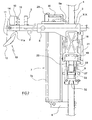
- Said bead breaker device 1 comprises an arm 2 able to slide horizontally along a sliding axis X-X, in a pipe 3 supported so that it can slide vertically on a pole 4 projecting cantilevered from a base (not illustrated).
- the arm 2 has a hexagonal prismatic cross section to avoid it rotating about the sliding axis X-X and is equipped at one end with a sleeve 5 on which the thrust is exerted to obtain the desired sliding.
- a locking/unlocking device 6 is associated with the pipe, suitable for allowing or preventing the sliding of the arm 2.
- the vertical sliding along the post 4 of the pipe-arm group 3, 2 is ensured by a jack 7 having the cylinder 7a and the stem 2b extending parallel to the post 4.
- the jack 7 is associated onto a support cross-member 8 fixed to the post 4.
- the pipe 3 is associated with the upper end of the stem 7b of the jack 7 through the interposition of a sled 9 provided with idle pins 32 that ensure the sliding along the post 4.
- the sled 9 is provided with a bracket 9a associated with the end of the stem 7b of the jack 7 through a trunnion 20 ( fig. 5 ).
- An orientable bead breaker device 10 suitable for breaking the bead of a tire of a wheel removably fixed onto rotary support and locking means of the rim (not illustrated), is associated with the end close to the sleeve 5 of the arm 2.
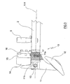
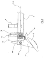
- the tool 10 is orientable between a first thrusting configuration, illustrated in figure 3 , and a second penetration configuration, illustrated in figure 4 through suitable actuation means, which shall be discussed hereafter.
- the tool 10 comprises an oblong support body 11 rotatably associated with the end of the arm 2 and a disc 12 fixed to an end of the support body 11, suitable for cooperating with the bead of the tire.
- the support body 11 of the disc 12 tilts about an articulation pin 13 arranged horizontally and perpendicular to the sliding axis X-X, as can clearly be seen in the figures.
- the actuation means comprise a thrusting body 14 and elastic means, such as a spring 17, cooperating with the tool.
- the thrusting body 14 is actuated in contrast to the action of the spring 17.
- the end of the support body 11 opposite the one where the disc is associated cooperates with the thrusting body 14 actuated by a cylinder-piston group 15 between a first extension position ( fig. 3 ) in which the tool 10 is forced into the first thrusting configuration against the action of the return spring 17 and a second release position ( fig. 4 ) in which the tool 10 goes into the second penetration configuration under the action of the spring 17.
- the cylinder-piston group 15 actuating the thrusting body 14 is in the form of a pneumatic jack arranged parallel to the axis X-X and fixed to a plate 16 cantilevered from the sliding arm 2 near to the tool 10.
- the end opposite the disc 12 of the support body 11 is constantly in abutment against the thrusting body 14 that is actuated parallel to the axis X-X by the jack 15, in contrast to the spring 17, in order to ensure the thrusting position of the tool 10.
- Said spring 17 is arranged vertically and perpendicular to the sliding axis X-X of the arm 2, i.e. perpendicular to the axis of the articulation pin 13.
- said support body 11 is provided with a nose 11a, extending along the sliding axis X-X, arranged in abutment against the spring 17.
- the support body 11 of the disc 12 can have a central projection 11b ( figs 3 , 4 ) that goes into abutment against the end of the arm 2 acting as a limit switch, when the tool 10 is in the penetration position.
- Said tilting means allow the rotation of the arm 2 about a rotation axis Y-Y parallel to and distal from the sliding axis X-X.
- the tilting means comprise a tilting frame 18 hinged at a forked end thereof 18a to the sled 9 through an articulation pin 19 extending along the rotation axis Y-Y and at the other end associated with the pipe 3, engagement means and disengagement means respectively suitable for locking the frame 18 in a work position and for unlocking the same frame to allow it to tilt.
- the engagement means comprise an upper fastening pin 21 and a lower fastening pin 22 having the respective axes extending parallel and symmetrically to said rotation axis Y-Y, at least one return spring 23 placed between the two fastening pins 21, 22 and at least one fastening body 24 associated with the tilting frame 18.
- the fastening pins 21, 22 are each slidably inserted in a respective pair of opposite slots 25, 26 formed laterally on the sled 9 and extending vertically for a limited portion.
- the at least one return spring 23 are two helical torsion springs 23 arranged vertically and inside the sled 9 and having the ends attached to the fastening pins 21, 22.
- the springs 23 apply a force drawing the fastening pins 21, 22 towards each other, up to the limit switch allowed by the slots 25, 26.
- the fastening bodies 24, two in number, are integrally associated on opposite sides with the tilting frame 18 and each of them is provided with a pair of U-shaped grooves 24a suitable for alternately engaging with the ends of the fastening pins 21, 22 that come out from the slots 25, 26 of the sled 9.
- the disengagement means are actuated, which preferably comprise a pair of opposite jacks 27 fixed on the inside to the sled 9, respectively cooperating with the upper fastening pin 21 and lower fastening pin 22 and able to be actuated in contrast to the return springs 23 ( fig. 6 ).
- the actuation of the jacks 27 can be carried out through a button 29 arranged on a handle 30 fixed to the pipe 3.
- a button 29 arranged on a handle 30 fixed to the pipe 3.
- damping means of the rotation speed about the rotation axis Y-Y for example providing a pneumatic damping jack 31 associated at one end with the sled 9 at the articulation pin 13 and at the other end with the pipe 3 ( fig. 2 ).
- the bead breaker tool 10 is positioned, acting on the handle 5 after having unlocked the locking/unlocking device 6 present on the pipe 3, at a distance from the post 4 such as to allow the disc 12 to reach the bead of the tire.
- the tool 10 is moved closer to the bead of the tire through the actuation of the jack 7 that drags the sled 9 vertically along the post 4 and with it the pipe 3, the arm 2 and thus the tool 10.
- the bead breaking occurs substantially in two steps: the first a thrusting step, in which the bead is detached from the edge of the rim to which it is attached through a thrust applied parallel to the axis of the wheel, the second a penetration step, in which the disc penetrates inside the tire positioning itself between the bead and the edge of the rim.
- the tool 10 takes up the first thrusting configuration and the second penetration configuration, respectively.
- the first thrusting configuration is ensured by the thrusting body 14 that is actuated in its extension position in contrast to the spring 17.
- the second penetration configuration is ensured by the action of the spring 17 that, when the action of the thrusting body 14 has stopped, applies a thrust onto the nose 11a of the support body 11 to which the disc 12 is fixed, making it rotate about the pin 13 by a few degrees. of course, the thrust stops its effects when the projection 11b goes into abutment against the end of the arm 2.
- the tilting means are actuated by pressing on the button 29 on the handle 30 fixed to the pipe 3.
- the button 29 actuates the pair of jacks 27 that thrust apart the pins 21 and 22, which are free to slide in the pairs of slots 25 and 26, until they are detached from the pair of U-shaped recesses 24a of the fastening bodies 24.
- the tilting frame 18, integral with the fastening bodies 24, is free to rotate about the pin 19 tilting down (or vice-versa, if one starts at the bottom side of the tire), where it shall attach to the lower pin 22 once the action of the jacks 27 has stopped, in virtue of the action applied by the return springs 23.
- the bead breaker device according to the present invention allows the requirements to be satisfied and the drawbacks mentioned in the introductory part of the present description with reference to the prior art to be overcome.
- the bead breaker device according to the present invention is simple and cost-effective to make and allows effective bead breaking.
- the group formed from the actuation means of the tool and the tool itself is entirely housed at the end of the arm and it can also be associated with arms of conventional bead breaker devices, occupying little space and therefore being very practical.
- said bead breaker device allows the bead of a tire to be broken on both sides without needing to tilt the wheel.
- a man skilled in the art can bring numerous modifications and variants to the bead breaker device described above in order to satisfy contingent and specific requirements, all of which are covered by the scope of protection of the invention, as defined by the following claims.
Landscapes
- Engineering & Computer Science (AREA)
- Mechanical Engineering (AREA)
- Tires In General (AREA)
Claims (15)
- Wulstabdrückvorrichtung (1) einschließlich:- eines Arms (2), der in einem Rohr (3) horizontal auf einer Gleitachse (X-X) bewegbar ist, das Rohr (3) so gelagert, dass es vertikal auf einer Säule (4) bewegbar ist, welche freistehend von einer Basis nach oben ragt; ein ausrichtbares Wulstabdrückwerkzeug (10), das mit einem Ende des Arms (2) verbunden und dazu geeignet ist, den Reifenwulst von einem Rad abzudrücken, welches entfernbar auf einer drehbaren Trägerfläche und den Schließelementen der Felge befestigt ist, das Werkzeug (10) beinhaltet ferner einen gelenkig drehbaren Trägerkörper (11), welcher drehbar mit dem Ende des Arms verbunden ist und an dessen einem Ende eine Wulstabdrück-Scheibe (12) befestigt ist;- Betätigungselementen (14, 15, 17), die geeignet sind zum Ausrichten des Werkzeugs (10) in einer ersten Andrückanordnung und einer zweiten Eindringungsanordnung, dadurch gekennzeichnet, dass die Betätigungselemente (14, 15, 17) einen Andrückkörper (14) und elastische Elemente (17) beinhalten, die mit dem Werkzeug (10) zusammenarbeiten, wobei der Andrückkörper (14) in Anlage an einen Teil des gelenkig drehbaren Trägerkörpers (11) betätigt werden kann und außerdem in einer ersten Verlängerungsstellung betätigt werden kann, die im Gegensatz zum Betrieb der elastischen Elemente (17) steht, und in einer zweiten Lösestellung, in der die von den elastischen Elementen (17) ausgeübte Kraft herrscht.
- Wulstabdrückvorrichtung (1) nach Patentanspruch 1, wobei das der Scheibe (12) entgegen gesetzte Ende des gelenkig drehbaren Trägerkörpers (11) fortwährend in Anlage an den Andrückkörper (14) steht.
- Wulstabdrückvorrichtung (1) nach Patentanspruch 1 oder 2, wobei der Andrückkörper (14) von einer Zylinderkolbengruppe (15) betrieben wird, die auf einer von dem Gleitarm (2) freistehenden Platte (16) angeordnet ist.
- Wulstabdrückvorrichtung (1) nach Patentanspruch 3, wobei die Zylinderkolbengruppe (15) ein pneumatischer Hebebock ist.
- Wulstabdrückvorrichtung (1) nach Patentanspruch [4] 1, wobei der Trägerkörper (11) eine Ausbuchtung (11b) aufweist, die sich in Anlage an das Ende des Arms (2) bewegt, wenn sich das Werkzeug (10) in der Eindringungsstellung befindet.
- Wulstabdrückvorrichtung (1) nach Patentanspruch 1, wobei der Trägerkörper (11) mit einem Vorsprung (11a) ausgestattet ist, der mit den elastischen Elementen (17) zusammenarbeitet.
- Wulstabdrückvorrichtung (1) nach Patentanspruch 1, wobei die elastischen Elemente eine Feder (17) beinhalten, die fest in einer am Ende des Arms (2) geformten Vertiefung eingefügt und quer zur Gleitachse (X-X) des Arms (2) angeordnet ist.
- Wulstabdrückvorrichtung (1) nach Patentanspruch 1, einschließlich Kippelementen, die geeignet sind zum Kippen des Gleitarms (2), um diesen auf die gegenüberliegende Seite des entfernbar auf der drehbaren Trägerfläche und den Schließelementen der Felge befestigten Rades zu bringen, wobei die Kippelemente die Rotation des Arms (2) auf einer Rotationsachse (Y-Y) ermöglichen, welche parallel zur Gleitachse (X-X) liegt und von dieser entfernt ist.
- Wulstabdrückvorrichtung (1) nach Patentanspruch 8, wobei die Kippelemente einen Kipprahmen (18) beinhalten, der an einem Ende zu einem Schlitten (9) kippbar ist, welcher so angeordnet ist, dass er vertikal auf der Säule (4) durch einen Gelenkbolzen (19) gleiten kann, der sich entlang der Rotationsachse (Y-Y) erstreckt und der am anderen Ende mit dem Rohr (3), den Arretierungselementen (21, 22, 23, 24) und den Löseelementen (27) verbunden ist, welche jeweils dazu geeignet sind, den Rahmen (18) in einer Arbeitsstellung zu arretieren und ihn wieder zu lösen, damit dieser gekippt werden kann.
- Wulstabdrückvorrichtung (1) nach Patentanspruch 9, wobei die Arretierungselemente (21, 22, 23, 24) einen oberen Befestigungsstift (21) und einen unteren Befestigungsstift (22) beinhalten, deren Achsen parallel und symmetrisch zur Rotationsachse (Y-Y) verlaufen; die Befestigungsstifte (21, 22) sind jeweils bewegbar eingeführt in ein zugehöriges Paar gegenüberliegender Schlitze (25, 26) auf dem Schlitten (9) und erstrecken sich vertikal auf einer begrenzten Strecke, wobei sich wenigstens eine Rückholfeder (23) zwischen den beiden Befestigungsstiften (21, 22) befindet, die zum Anwenden einer Kraft dient, welche die Stifte (21, 22) zusammenzieht und wenigstens ein Befestigungskörper (24), der mit dem Kipprahmen (18) verbunden und dazu geeignet ist, sich abwechselnd an die Enden jedes Befestigungsstiftes (21, 22) anzuschließen.
- Wulstabdrückvorrichtung (1) nach Patentanspruch 10, wobei der Befestigungskörper (24) mit einem Paar U-förmiger Aushöhlungen (24a) ausgestattet ist, die dazu geeignet sind, in die Enden der Befestigungsstifte (21, 22) einzurasten.
- Wulstabdrückvorrichtung (1) nach Patentanspruch 10, wobei die Löseelemente ein Paar an dem Schlitten (9) angebrachte Hebeböcke (27) beinhalten, welche jeweils mit dem oberen Befestigungsstift (21) und dem unteren Befestigungsstift (22) zusammenarbeiten und die im Gegensatz zu wenigstens einer Rückholfeder (23) betätigt werden können, um das Loslösen der Befestigungsstifte (21, 22) von dem Befestigungskörper (24) zu bewirken, damit dieser gekippt werden kann.
- Wulstabdrückvorrichtung (1) nach Patentanspruch 12, wobei die Hebeböcke (27) durch einen Knopf (29) betätigt werden, der auf einem am Rohr (3) befestigten Griff (30) angebracht ist.
- Wulstabdrückvorrichtung (1) nach Patentanspruch 8 einschließlich Dämpfungselementen (31) zur Dämpfung der Rotationsgeschwindigkeit des Arms (2) auf der Rotationsachse (Y-Y).
- Wulstabdrückvorrichtung (1) nach Patentanspruch 14, wobei die Dämpfungselemente einen pneumatischen Hebebock beinhalten.
Applications Claiming Priority (2)
| Application Number | Priority Date | Filing Date | Title |
|---|---|---|---|
| ITRE20040072 | 2004-06-15 | ||
| IT000072A ITRE20040072A1 (it) | 2004-06-15 | 2004-06-15 | Dispositivo stallonatore |
Publications (2)
| Publication Number | Publication Date |
|---|---|
| EP1607247A1 EP1607247A1 (de) | 2005-12-21 |
| EP1607247B1 true EP1607247B1 (de) | 2008-07-09 |
Family
ID=34938278
Family Applications (1)
| Application Number | Title | Priority Date | Filing Date |
|---|---|---|---|
| EP05076144A Expired - Lifetime EP1607247B1 (de) | 2004-06-15 | 2005-05-17 | Reifenabdrückvorrichtung |
Country Status (6)
| Country | Link |
|---|---|
| US (1) | US7108035B2 (de) |
| EP (1) | EP1607247B1 (de) |
| JP (1) | JP4887003B2 (de) |
| DE (1) | DE602005007966D1 (de) |
| ES (1) | ES2309650T3 (de) |
| IT (1) | ITRE20040072A1 (de) |
Families Citing this family (23)
| Publication number | Priority date | Publication date | Assignee | Title |
|---|---|---|---|---|
| US9239329B2 (en) | 2006-12-18 | 2016-01-19 | Japan Science And Technology Agency | Method of measuring interaction between biomaterial and sugar chain, method of evaluating biomaterial in sugar chain selectivity, method of screening biomaterial, method of patterning biomaterials, and kits for performing these methods |
| DE602007004441D1 (de) * | 2007-04-05 | 2010-03-11 | Snap On Equipment S R L A Unic | Reifenwechselgerät |
| ITMO20070144A1 (it) * | 2007-04-27 | 2008-10-28 | Gino Ferrari | "apparato pressore" |
| JP2009227006A (ja) * | 2008-03-19 | 2009-10-08 | Onodani Kiko Kk | タイヤ着脱装置のタイヤビード案内装置 |
| JP5563742B2 (ja) * | 2008-03-19 | 2014-07-30 | 小野谷機工株式会社 | タイヤ着脱装置のマウントプレス装置 |
| JP5478024B2 (ja) * | 2008-03-19 | 2014-04-23 | 小野谷機工株式会社 | タイヤ着脱装置のビードプレス装置 |
| ITRE20080037A1 (it) * | 2008-04-21 | 2009-10-22 | Corghi Spa | "macchina smontagomme e relativo metodo di stallonatura" |
| JP5325026B2 (ja) * | 2009-06-11 | 2013-10-23 | 小野谷機工株式会社 | タイヤ着脱装置におけるツール伸縮・反転機構 |
| JP5026476B2 (ja) * | 2009-07-30 | 2012-09-12 | 小野谷機工株式会社 | タイヤ着脱機に装着されるビード落し装置 |
| CN101934689A (zh) * | 2009-06-30 | 2011-01-05 | 小野谷机工株式会社 | 胎圈拆卸臂及备有胎圈拆卸臂的轮胎拆卸装置及轮胎拆卸方法 |
| IT1396144B1 (it) * | 2009-11-03 | 2012-11-16 | Corghi Spa | Dispositivo di sollevamento di un fianco inferiore di uno pneumatico, in una macchina smontagomme. |
| BR112013020403A2 (pt) * | 2011-02-11 | 2016-10-25 | Austin Engineering Ltd | aparelho de manipulação de artigo |
| JP6039881B2 (ja) * | 2011-03-02 | 2016-12-07 | 小野谷機工株式会社 | タイヤ着脱装置 |
| JP5954932B2 (ja) * | 2011-03-02 | 2016-07-20 | 小野谷機工株式会社 | タイヤ着脱装置 |
| US9950580B2 (en) * | 2012-01-31 | 2018-04-24 | Android Industries Llc | Bead seater apparatus and method for using the same |
| ITMO20120206A1 (it) * | 2012-09-04 | 2014-03-05 | M & B Engineering S R L | Macchina smontagomme |
| ITMO20130110A1 (it) * | 2013-04-23 | 2014-10-24 | Giuliano Group Spa | Gruppo stallonatore per macchine smontagomme o simili |
| EP3517326B1 (de) * | 2014-09-15 | 2022-12-28 | NEXION S.p.A. | Radservicemaschine und verfahren zur durchführung einer diagnosebewertung eines fahrzeugrades |
| CN107323185B (zh) * | 2017-08-08 | 2022-12-13 | 鞍山强锋久盛科技发展有限公司 | 重型矿用汽车轮胎扒胎机 |
| IT201800009322A1 (it) | 2018-10-10 | 2020-04-10 | Butler Eng And Marketing Spa | Macchina di montaggio e/o smontaggio di ruote di veicoli, in particolare ruote da camion |
| CN111823793B (zh) * | 2020-06-30 | 2022-05-17 | 广州赫力汽车维修设备有限公司 | 一种轮胎拆装机构及轮胎拆装机 |
| IT202100001238A1 (it) | 2021-01-25 | 2022-07-25 | Snap On Equip Srl Unico Socio | Apparato smontagomme |
| IT202100001235A1 (it) | 2021-01-25 | 2022-07-25 | Snap On Equip Srl Unico Socio | Apparato smontagomme con utensile a basculamento automatico |
Family Cites Families (6)
| Publication number | Priority date | Publication date | Assignee | Title |
|---|---|---|---|---|
| US5226465A (en) * | 1991-02-19 | 1993-07-13 | Stahlgruber Otto Gruber Gmbh & Co. | Mounting device for motor vehicle tires |
| EP0499825B1 (de) * | 1991-02-19 | 1994-04-13 | STAHLGRUBER Otto Gruber GmbH & Co. | Demontiervorrichtung für KFZ-Luftreifen |
| IT1316726B1 (it) * | 2000-05-18 | 2003-05-12 | Mondolfo Ferro Spa | Macchina per il montaggio e lo smontaggio dei pneumatici delle ruotedegli autoveicoli |
| IT1319468B1 (it) * | 2000-05-22 | 2003-10-10 | Corghi Spa | Dispositivo stallonatore automatico per macchine smontagomme, emacchine smontagomme cosi' attrezzate |
| IT1319475B1 (it) * | 2000-08-03 | 2003-10-10 | Corghi Spa | Dispositivo automatico per lo smontaggio ed il montaggio deipneumatici, e macchine smontagomme cosi' attrezzate |
| ITVR20020013A1 (it) * | 2002-02-12 | 2003-08-12 | Butler Eng & Marketing | Gruppo di stallonamento e smontaggio di pneumatici da cerchioni particolarmente per macchine smontagomme. |
-
2004
- 2004-06-15 IT IT000072A patent/ITRE20040072A1/it unknown
-
2005
- 2005-05-17 EP EP05076144A patent/EP1607247B1/de not_active Expired - Lifetime
- 2005-05-17 ES ES05076144T patent/ES2309650T3/es not_active Expired - Lifetime
- 2005-05-17 DE DE602005007966T patent/DE602005007966D1/de not_active Expired - Lifetime
- 2005-05-23 US US11/134,456 patent/US7108035B2/en not_active Expired - Lifetime
- 2005-06-10 JP JP2005171415A patent/JP4887003B2/ja not_active Expired - Lifetime
Also Published As
| Publication number | Publication date |
|---|---|
| JP4887003B2 (ja) | 2012-02-29 |
| ES2309650T3 (es) | 2008-12-16 |
| DE602005007966D1 (de) | 2008-08-21 |
| JP2006001538A (ja) | 2006-01-05 |
| US7108035B2 (en) | 2006-09-19 |
| ITRE20040072A1 (it) | 2004-09-15 |
| EP1607247A1 (de) | 2005-12-21 |
| US20050274461A1 (en) | 2005-12-15 |
Similar Documents
| Publication | Publication Date | Title |
|---|---|---|
| EP1607247B1 (de) | Reifenabdrückvorrichtung | |
| EP2282898B1 (de) | Reifenwechselmaschine und verwandtes wulstabdrückverfahren | |
| EP1366933B1 (de) | Reifenmontage- und Wulstabdrück-Maschine | |
| US7343955B2 (en) | Tire changing machine | |
| EP1897709B1 (de) | Maschine zum Anbringen und Abnehmen von Fahrzeugreifen | |
| EP1052120A1 (de) | Mehrzweckstation für das Montieren und Demontieren von Konvetionell- und Spezialreifen | |
| US7341090B2 (en) | Assembling-disassembling machine provided with a overturnable mounting-dismounting tool | |
| EP2125394B1 (de) | Vorrichtung für reifenwechselmaschinen | |
| WO2009138322A1 (en) | A tyre-removing method and a tyre-changing machine | |
| JP5778955B2 (ja) | タイヤ上ビードの取外し方法 | |
| EP4169744B1 (de) | Maschine zur montage und demontage eines reifens in bezug auf eine entsprechende felge und radwartungsverfahren | |
| EP2974995B1 (de) | Vorrichtung zum Stützen eines Fahrzeugrades | |
| JP5026477B2 (ja) | タイヤ上ビードの取外し方法及びその装置 | |
| US9610812B2 (en) | Tire bead extraction device for tire-changing machines | |
| EP2281699B1 (de) | Einheit zum Wulstabdrücken von Reifen in einer Reifenwechselmaschine | |
| JP2011042303A (ja) | 回転テーブルを備えたタイヤ着脱装置 | |
| EP1479539A2 (de) | Maschine zum Auf- und Abmontieren von Reifen und Felgen von Kraftfahrzeugrädern | |
| EP1529666A2 (de) | Werkzeug für Reifenmontagemaschine | |
| CN111823793A (zh) | 一种轮胎拆装机构及轮胎拆装机 | |
| JP3600958B2 (ja) | 中子式タイヤの着脱装置 | |
| JP2011031645A (ja) | タイヤ着脱機に装着されるビード落し装置 | |
| CA2461648C (en) | Tire changing and bead breaker apparatus | |
| EP2078625B1 (de) | Vorrichtung zur Erleichterung der Montage oder Demontage von Reifen | |
| JP5026473B2 (ja) | タイヤ上ビードの取外し方法 | |
| CN111775640A (zh) | 一种可防止内胎损伤的大型卧式轮胎拆装机 |
Legal Events
| Date | Code | Title | Description |
|---|---|---|---|
| PUAI | Public reference made under article 153(3) epc to a published international application that has entered the european phase |
Free format text: ORIGINAL CODE: 0009012 |
|
| AK | Designated contracting states |
Kind code of ref document: A1 Designated state(s): AT BE BG CH CY CZ DE DK EE ES FI FR GB GR HU IE IS IT LI LT LU MC NL PL PT RO SE SI SK TR |
|
| AX | Request for extension of the european patent |
Extension state: AL BA HR LV MK YU |
|
| 17P | Request for examination filed |
Effective date: 20060208 |
|
| AKX | Designation fees paid |
Designated state(s): DE ES FR IT |
|
| 17Q | First examination report despatched |
Effective date: 20070314 |
|
| GRAP | Despatch of communication of intention to grant a patent |
Free format text: ORIGINAL CODE: EPIDOSNIGR1 |
|
| GRAS | Grant fee paid |
Free format text: ORIGINAL CODE: EPIDOSNIGR3 |
|
| GRAA | (expected) grant |
Free format text: ORIGINAL CODE: 0009210 |
|
| AK | Designated contracting states |
Kind code of ref document: B1 Designated state(s): DE ES FR IT |
|
| REF | Corresponds to: |
Ref document number: 602005007966 Country of ref document: DE Date of ref document: 20080821 Kind code of ref document: P |
|
| REG | Reference to a national code |
Ref country code: ES Ref legal event code: FG2A Ref document number: 2309650 Country of ref document: ES Kind code of ref document: T3 |
|
| PLBE | No opposition filed within time limit |
Free format text: ORIGINAL CODE: 0009261 |
|
| STAA | Information on the status of an ep patent application or granted ep patent |
Free format text: STATUS: NO OPPOSITION FILED WITHIN TIME LIMIT |
|
| 26N | No opposition filed |
Effective date: 20090414 |
|
| REG | Reference to a national code |
Ref country code: FR Ref legal event code: PLFP Year of fee payment: 12 |
|
| REG | Reference to a national code |
Ref country code: FR Ref legal event code: PLFP Year of fee payment: 13 |
|
| REG | Reference to a national code |
Ref country code: DE Ref legal event code: R082 Ref document number: 602005007966 Country of ref document: DE Representative=s name: MICHALSKI HUETTERMANN & PARTNER PATENTANWAELTE, DE Ref country code: DE Ref legal event code: R081 Ref document number: 602005007966 Country of ref document: DE Owner name: NEXION S.P.A., IT Free format text: FORMER OWNER: CORGHI S.P.A., CORREGGIO, REGGIO EMILIA, IT Ref country code: DE Ref legal event code: R082 Ref document number: 602005007966 Country of ref document: DE Representative=s name: RCD-PATENT GIESEN, SCHMELCHER & GRIEBEL PATENT, DE |
|
| REG | Reference to a national code |
Ref country code: ES Ref legal event code: PC2A Effective date: 20180529 Ref country code: FR Ref legal event code: PLFP Year of fee payment: 14 Ref country code: ES Ref legal event code: PC2A Owner name: NEXION S.P.A. Effective date: 20180529 |
|
| REG | Reference to a national code |
Ref country code: DE Ref legal event code: R082 Ref document number: 602005007966 Country of ref document: DE Representative=s name: RCD-PATENT GIESEN, SCHMELCHER & GRIEBEL PATENT, DE |
|
| REG | Reference to a national code |
Ref country code: FR Ref legal event code: CD Owner name: NEXION S.P.A., IT Effective date: 20180620 |
|
| P01 | Opt-out of the competence of the unified patent court (upc) registered |
Effective date: 20230530 |
|
| PGFP | Annual fee paid to national office [announced via postgrant information from national office to epo] |
Ref country code: DE Payment date: 20240529 Year of fee payment: 20 |
|
| PGFP | Annual fee paid to national office [announced via postgrant information from national office to epo] |
Ref country code: ES Payment date: 20240610 Year of fee payment: 20 |
|
| PGFP | Annual fee paid to national office [announced via postgrant information from national office to epo] |
Ref country code: FR Payment date: 20240527 Year of fee payment: 20 |
|
| PGFP | Annual fee paid to national office [announced via postgrant information from national office to epo] |
Ref country code: IT Payment date: 20240521 Year of fee payment: 20 |
|
| REG | Reference to a national code |
Ref country code: DE Ref legal event code: R071 Ref document number: 602005007966 Country of ref document: DE |
|
| REG | Reference to a national code |
Ref country code: ES Ref legal event code: FD2A Effective date: 20250526 |
|
| PG25 | Lapsed in a contracting state [announced via postgrant information from national office to epo] |
Ref country code: ES Free format text: LAPSE BECAUSE OF EXPIRATION OF PROTECTION Effective date: 20250518 |