EP1606988A1 - Bodenkopiervorrichtung - Google Patents
Bodenkopiervorrichtung Download PDFInfo
- Publication number
- EP1606988A1 EP1606988A1 EP05010941A EP05010941A EP1606988A1 EP 1606988 A1 EP1606988 A1 EP 1606988A1 EP 05010941 A EP05010941 A EP 05010941A EP 05010941 A EP05010941 A EP 05010941A EP 1606988 A1 EP1606988 A1 EP 1606988A1
- Authority
- EP
- European Patent Office
- Prior art keywords
- piston
- piston rod
- pressure chamber
- seal
- pressure
- Prior art date
- Legal status (The legal status is an assumption and is not a legal conclusion. Google has not performed a legal analysis and makes no representation as to the accuracy of the status listed.)
- Granted
Links
- 230000006978 adaptation Effects 0.000 title 1
- 238000007789 sealing Methods 0.000 claims abstract description 10
- 239000002689 soil Substances 0.000 claims 1
- 239000012530 fluid Substances 0.000 description 9
- 230000000630 rising effect Effects 0.000 description 6
- 230000001419 dependent effect Effects 0.000 description 5
- 230000033228 biological regulation Effects 0.000 description 4
- 230000000903 blocking effect Effects 0.000 description 3
- 238000010586 diagram Methods 0.000 description 3
- 230000000694 effects Effects 0.000 description 2
- 238000013459 approach Methods 0.000 description 1
- 230000007423 decrease Effects 0.000 description 1
- 230000003247 decreasing effect Effects 0.000 description 1
- 238000003306 harvesting Methods 0.000 description 1
- 238000004519 manufacturing process Methods 0.000 description 1
- 238000000034 method Methods 0.000 description 1
- 230000001105 regulatory effect Effects 0.000 description 1
Images


Classifications
-
- A—HUMAN NECESSITIES
- A01—AGRICULTURE; FORESTRY; ANIMAL HUSBANDRY; HUNTING; TRAPPING; FISHING
- A01D—HARVESTING; MOWING
- A01D41/00—Combines, i.e. harvesters or mowers combined with threshing devices
- A01D41/12—Details of combines
- A01D41/14—Mowing tables
- A01D41/141—Automatic header control
Definitions
- the invention relates to a Bodenkopiervortechnische according to the preamble of Claim 1.
- From DE 295 07 623 is a discharge device for a hydraulic Lifting device of a commercial vehicle for lifting a working device from a lowered working position in a raised transport position with a through a hydraulic pump by pressurizable hydraulic lifting cylinder known, the hydraulic lifting line in working position to reduce the Bearing force of the implement on the ground through the Relief device can be acted upon with a residual pressure.
- the hydraulic lifting line in working position to reduce the Bearing force of the implement on the ground through the Relief device can be acted upon with a residual pressure.
- a disadvantage of the said devices is that the regulation of Pad pressure of the attachment is very inaccurate, there when lifting and Lowering the attachment very high frictional forces on the retracting and retracting Lifting cylinders act, which are disregarded in the regulation.
- the invention is therefore based on the object, the lifting device of the above be further developed such that a more precise regulation of Pad pressure is possible.
- a differential cylinder can be used be, in which by the movement of the piston rod in the cylinder housing occurring friction forces are minimized.
- the leakage oil flow flows during retraction and extension of the piston rod from the piston pressure chamber in the piston rod pressure chamber, so that the Piston seal must not be performed oil-tight and therefore cost is to produce.
- the piston rod seal through smoothed and / or lubricated contact surfaces on the piston rod and / or produced on the cylinder housing, so that no further additional Seals must be provided.
- the piston seal by a circumferential gap formed by the choice of a wide fit between piston rod and Cylinder body is inexpensive to produce.
- piston pressure chamber via a main pressure line can be the piston rod seal for low pressures designed, that is to say, of lower quality.
- the return line is over Directional valve connected to the main pressure line.
- the attachment is suspended resiliently on the machine frame and become the forces acting on the attachment when sliding on the ground forces reduces damage to the cutting unit and the machine frame be avoided.
- Fig. 1 is schematically the front part of a combine harvester 1 with the Bodenkopiervor512 according to the invention shown in the side view.
- a Cutting unit 4 executed header 5 arranged at the vertically pivoting feed shaft 3 of the combine harvester 1 .
- the piston rods 8 of the working cylinder 7 hinged to the Feed shaft 3 and the cylinder housing 9 of the working cylinder 7 hinged to the Machine frame 6 of the combine 1 are connected.
- the cutting unit 4 With the swiveling Feed shaft 3 is the cutting unit 4 with the working cylinders 7 on a Cutting height L adjustable.
- the cutting unit 4 is known per se Way using more, not shown lifting cylinder over the Feeder shaft 3 adjustable connected to the intake shaft 3. The from the Cutting unit 4 picked crop passes through the feed chute 3 to a Drehisk not shown in the combine harvester 1, which processes the crop.
- a pressure sensor 10 is arranged, which controls the pressure P detected in the working cylinders 7.
- the pressure sensors 10 and the rotation angle sensors 12 are provided with a Control unit 13 is connected to the one generated by the pressure sensor 10 Pressure signal D and the generated by the rotation angle sensors 12 Cutting height signals S are transmitted.
- the control unit 13 with an operating unit 14, via which an operator 15 a desired contact pressure 16 and a target cutting height 17, which is stored in the control unit 13 become.
- the control unit 13 regulates in dependence on the pressure signals D or the cutting height signals S connected to the working cylinders 7 Hydraulic unit 18 of the Bodenkopiervortechnisch 2, with the working cylinder.
- Both Working cylinder 7 are designed as single-acting differential cylinder 20, wherein a piston 19 fixedly connected to the piston 19, the cylinder housing 9 in a piston pressure chamber 22 and a piston rod pressure chamber 21 separates.
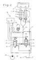
- the working cylinders 7 are connected to a valve block 23 at the one Hydraulic pump 24, a tank 25, and a pressure accumulator 26 are connected.
- a valve block 23 At the one Hydraulic pump 24, a tank 25, and a pressure accumulator 26 are connected.
- a valve block 23 itself takes two switchable valves 27, 28 and a Check valve 29 on.
- the hydraulic pump 24 is connected via a main pressure line 30 with the Piston pressure chambers 22 of the working cylinder 7 connected when the directional control valve 27 in a lifting position 34 is connected. Behind the directional control valve 27 is in Flow direction of the hydraulic pump 24, the check valve 29 in the Main pressure line 30 arranged so that it flows a fluid from the Working cylinders 7 back towards the tank 25 locks when the directional control valve 27 in a blocking position 32 is connected.
- the piston rod pressure chambers 21 of the working cylinder 7 are via return lines 31 permanently connected to the tank 25. Between the main pressure line 30 and the return lines 31, the directional control valve 28 is connected, which depending on Switching position, a fluid flow from the main pressure line 30 to the return line 31st locks or releases.
- the accumulator 26 is parallel to the working cylinders 7 to the Main pressure line 30 connected.
- the directional control valve 27 is in a lifting position 34th connected.
- the hydraulic pump 24 acts on the piston pressure chambers 22 and the Pressure accumulator 26 with fluid, whereby a pressure P builds up with the Pressure sensor 10 is measured.
- a limit pressure moves the Piston rod 8 of the working cylinder 7 and raises the header 5.
- the second directional valve 28 is in a Lowered position 35 switched.
- the Main pressure line 30 and the return lines 31 short-circuited. The fluid flows coming from the main pressure line 30 via the directional control valve 28 and the Return lines 31 back into the tank 25th
- the pressure P in the piston pressure chambers 22 of the working cylinder 7 drops because the Piston rods 8, for example, as a result of over a Bodenunebenheit 36th sliding header 5 extend and thereby the piston pressure chambers 22nd enlarge flow as pressure equalization from the accumulator 26 fluid flows in the Piston pressure chambers 22, whereby the header 5 is relieved. Conversely flow the fluid flows from the piston pressure chambers 22 back into the pressure accumulator 26, when the piston rods 8 retract and the header 5 lowered again becomes.
- the switching valves 27, 28 and the pressure sensor 10 are connected to the control unit 13 connected.
- the control unit 13 controls the switching valves 27, 28 as a function of the pressure P. If the pressure P drops below the target bearing pressure stored in the control unit 13 16, the switching valve 27 is switched to the lifting position 34, so that the Hydraulic pump 24, the piston pressure chambers 22 and the accumulator 26 as long with Fluid acts until the pressure P corresponds to the desired contact pressure 16.
- the switching valve 28 is switched to the lowering position 35, so that the fluid from the piston pressure chambers 22 and the accumulator 26 flow into the tank 25 can until the pressure P corresponds to the target contact pressure 16.
- FIG. 3 shows the combine harvester 1 when moving the cutting unit 4 via a Uneven ground 36.
- the cutting unit 4 is from the working cylinders 7 with Holding forces H1, H2 held in proportion to the pressure P in the working cylinders. 7 are. If the cutting unit 3 crosses a ground unevenness 36, then the on and and Extending the piston rods 8 from the cylinder housing 9 friction forces R1, R2, R3, R4 which are opposite to the movement of the piston rods 8.
- Fig. 4 is a diagram of the proportional dependence between the Holding force H1 and the pressure P in a linearly rising curve 37 shown.
- both curves 37, 38th have the same starting point and the same end point.
- a above the linear rising curve 37 lying region 39 of the hysteresis curve 38 applies to the retracting at decreasing pressure P piston rod 8 and below the linear rising curve 37 lying region 40 of the hysteresis curve 38th This applies to the piston rod 8 which extends as the pressure P increases.
- two hysteresis curve 38 results different large resulting forces KE, KA during retraction and extension of Piston rod 8 during the linear rising curve 37 the pressure P1 exactly assigns a holding force H.
- the resulting force KE is around the friction force R1 greater than the holding force H and the resultant force KA about the frictional force R3 smaller than the holding force H.
- the hysteresis curve 38 allows an unambiguous assignment of the pressure P. a resultant force K1 and is therefore inappropriate to the Holding force H1 precise to regulate.
- the friction of the Working cylinder can be reduced or eliminated, so that the hysteresis Curve 38 to the linearly rising curve 37 equalizes or at least approaches.
- Fig. 5 shows the working cylinder 7 of the invention Bodenkopiervorraum.
- the piston pressure chamber 22 is provided with a piston seal 41 with respect to the Piston rod pressure chamber 21 and the piston rod pressure chamber 21 with a Kolbenstangenababdichtung 42 sealed from the environment 43. Of the Piston pressure chamber 22 is subjected to a pressure of about 60-180 bar.
- Piston seal 41 Due to the less sealing compared to the piston rod seal 42 Piston seal 41, a leakage flow 44 between the piston 19 and Cylinder housing 9 from the piston pressure chamber 22 in the piston rod pressure chamber 21st flow when the piston rod 8 retracts or extends, with the piston rod stationary 8, the piston seal 41, however, is oil-tight.
- the piston rod pressure chamber 21 only serves to accommodate the leakage oil flow 44 and almost points Atmospheric pressure on.
- the less sealing piston seal 41 has the Advantage that they are less friction than the movement of the piston rod 8 Usually used, even with the movement of the piston rod 8 oil density Piston seal 41 caused.
- Piston rod seal 42 encloses the piston rod pressure chamber 21 Atmospheric pressure oil-tight.
- the more intensive sealing piston rod seal 42 has the advantage that it also has less friction than one usually used, even when pressurized oil-tight piston rod seal caused.
- the piston seal 41 is surrounded by a circumferential gap 47 between the piston 19 and the cylinder housing 9 is formed. This is by choosing a wide one Matching fit between the piston 19 and cylinder housing 9 inexpensive to manufacture.
- the piston rod seal 42 is smoothed in the embodiment and / or lubricated contact surfaces 45, 46 on the piston rod 8 and / or on Cylinder housing 9 formed in the movement of the piston rods 8 to each other slide, thereby no additional sealing components are required. It would also be conceivable, the piston seals 41 and the Piston rod seal 42 by known per se sealing elements such For example, form sealing rings.
- the differential cylinder 20 has the advantage that by the burden of Differential cylinder 20 occurring transverse forces Q from both the piston seal 41 as well as from the piston rod seal 42 are received. Thereby the lateral forces Q are lower, so that the proportionally dependent Friction forces R are also lower.
Landscapes
- Life Sciences & Earth Sciences (AREA)
- Environmental Sciences (AREA)
- Actuator (AREA)
- Fluid-Pressure Circuits (AREA)
- Discharging, Photosensitive Material Shape In Electrophotography (AREA)
- Soil Working Implements (AREA)
- Electrostatic Charge, Transfer And Separation In Electrography (AREA)
Abstract
Description
- Fig.1
- den vorderen Teil eines schematisch dargestellten Mähdreschers mit einer Bodenkopiervorrichtung;
- Fig.2
- die Hydraulikschaltung des Hydraulikaggregates,
- Fig.3
- den Mähdrescher 1 bei Bewegung des Schneidwerks 4 über eine Bodenunebenheit,
- Fig.4
- das Diagramm mit linear ansteigender Stützlast und hystereseförmiger Stützlast,
- Fig.5
- den Arbeitszylinder der erfindungsgemäßen Bodenkopiervorrichtung.
- 1
- Mähdrescher
- 2
- Bodenkopiervorrichtung
- 3
- Einzugschacht
- 4
- Schneidwerk
- 5
- Erntevorsatz
- 6
- Maschinenrahmen
- 7
- Arbeitszylinder
- 8
- Kolbenstange
- 9
- Zylindergehäuse
- 10
- Drucksensor
- 11
- Tastbügel
- 12
- Drehwinkelsensor
- 13
- Steuereinheit
- 14
- Bedieneinheit
- 15
- Bediener
- 16
- Soll-Auflagedruck
- 17
- Soll-Schnitthöhe
- 18
- Hydraulikaggregat
- 19
- Kolben
- 20
- Differentialzylinder
- 21
- Kolbenstangendruckraum
- 22
- Kolbendruckraum
- 23
- Ventilblock
- 24
- Hydraulikpumpe
- 25
- Tank
- 26
- Druckspeicher
- 27
- Wegeventil
- 28
- Wegeventil
- 29
- Rückschlagventil
- 30
- Hauptdruckleitung
- 31
- Rücklaufleitung
- 32
- Sperrstellung
- 33
- Sperrstellung
- 34
- Hebestellung
- 35
- Senkstellung
- 36
- Bodenunebenheit
- 37
- Linear ansteigende Kurve
- 38
- Hystereseförmige Kurve
- 39
- Bereich
- 40
- Bereich
- 41
- Kolbenabdichtung
- 42
- Kolbenstangenabdichtung
- 43
- Umgebung
- 44
- Leckölstrom
- 45
- Berührungsfläche
- 46
- Berührungsfläche
- 47
- Spalt
- D
- Drucksignal
- L
- Schnitthöhe
- P
- Druck
- S
- Schnitthöhensignal
- H, H 1, H2
- Haltekraft
- K1, K2; KE, KA
- resultierende Kraft
- R1, R2, R3, R4
- Reibungskraft
Claims (1)
- Bodenkopiervorrichtung (2) zum Bodenkopieren von an einer selbstfahrenden Erntemaschine montierbaren Emtevorsätzen (5) mit wenigstens einem Arbeitszylinder (7) zum bodenkopierenden Heben und Senken des Erntevorsatzes (5), wobei der Arbeitszylinder (7) ein Differentialzylinder (20) ist, der von einem Kolben (19) mit einer Kolbenstange (8) und von einem Zylindergehäuse (9) gebildet wird und der Kolben (19) das Zylindergehäuse (9) in einen Kolbendruckraum (22) und einen Kolbenstangendruckraum (21) teilt,
mit einer Kolbenabdichtung (41), die den Kolbendruckraum (22) gegenüber dem Kolbenstangendruckraum (21) abdichtet,
mit einer Kolbenstangenabdichtung (42), die den Kolbenstangendruckraum (21) gegenüber der Umgebung (43) abdichtet,
dadurch gekennzeichnet, dass durch eine im Vergleich zur Kolbenstangenabdichtung (42) weniger abdichtende Kolbenabdichtung (41) ein Leckölstrom (44) fließen kann und
gleichzeitig eine im Vergleich zur Kolbenabdichtung (41) dichtere Kolbenstangenabdichtung (42) den Kolbenstangendruckraum (21) öldicht abschließt.2. Bodenkopiervorrichtung nach Anspruch 1,
dadurch gekennzeichnet, dass der Leckölstrom (44) beim Ein- und Ausfahren der Kolbenstange (22) vom Kolbendruckraum (22) in den Kolbenstangendruckraum (21) fließt.3. Bodenkopiervorrichtüng nach Anspruch 1,
dadurch gekennzeichnet, dass die Kolbenstangenabdichtung (42) bei niedrigem Druck öldicht ist.4. Bodenkopiervorrichtung nach wenigstens einem der vorhergehenden Ansprüche,
dadurch gekennzeichnet, dass die Kolbenstangenabdichtung (42) durch geglättete und /oder geschmierte Berührungsflächen (45, 46) an der Kolbenstange (8) und/oder am Zylindergehäuse (9) gebildet wird.5. Bodenkopiervorrichtung nach wenigstens einem der vorhergehenden Ansprüche,
dadurch gekennzeichnet, dass die Kolbenabdichtung (41) durch einen umlaufenden Spalt (47) gebildet wird.6. Bodenkopiervorrichtung nach wenigstens einem der vorhergehenden Ansprüche,
dadurch gekennzeichnet, dass der Differentialzylinder (20) einfach wirkend betrieben wird.7. Bodenkopiervorrichtung nach wenigstens einem der vorhergehenden Ansprüche,
dadurch gekennzeichnet, dass der Kolbendruckraum (22) über eine Hauptdruckleitung (30) druckbeaufschlagt wird.8. Bodenkopiervorrichtung nach wenigstens einem der vorhergehenden Ansprüche,
dadurch gekennzeichnet, dass der Kolbenstangendruckraum (21) des Differentialzylinders (20) über eine Rücklaufleitung (31) permanent mit einem Tank (25) verbunden ist.9. Bodenkopiervorrichtung nach wenigstens einem der vorhergehenden Ansprüche;
dadurch gekennzeichnet, dass die Rücklaufleitung (31) über ein Wegeventil (27) mit der Hauptdruckleitung (30) verbunden ist.10. Bodenkopiervorrichtung nach wenigstens einem der vorhergehenden Ansprüche;
dadurch gekennzeichnet, dass parallel zum Differentialzylinder (20) wenigstens ein Druckspeicher (26) geschaltet ist.
Applications Claiming Priority (2)
| Application Number | Priority Date | Filing Date | Title |
|---|---|---|---|
| DE102004028396A DE102004028396A1 (de) | 2004-06-14 | 2004-06-14 | Bodenkopiervorrichtung |
| DE102004028396 | 2004-06-14 |
Publications (2)
| Publication Number | Publication Date |
|---|---|
| EP1606988A1 true EP1606988A1 (de) | 2005-12-21 |
| EP1606988B1 EP1606988B1 (de) | 2007-08-15 |
Family
ID=34936737
Family Applications (1)
| Application Number | Title | Priority Date | Filing Date |
|---|---|---|---|
| EP05010941A Expired - Lifetime EP1606988B1 (de) | 2004-06-14 | 2005-05-20 | Bodenkopiervorrichtung |
Country Status (3)
| Country | Link |
|---|---|
| EP (1) | EP1606988B1 (de) |
| AT (1) | ATE369729T1 (de) |
| DE (2) | DE102004028396A1 (de) |
Cited By (5)
| Publication number | Priority date | Publication date | Assignee | Title |
|---|---|---|---|---|
| EP1872645A1 (de) | 2006-06-26 | 2008-01-02 | Deere & Company | Hebezylinder zur Verriegelung eines Erntevorsatzgerätes einer Erntemaschine |
| US8302398B2 (en) | 2008-08-29 | 2012-11-06 | Deere & Company | Work machine with drive train coupled turbo compounding |
| DE102006038801B4 (de) * | 2006-08-18 | 2014-02-06 | Amazonen-Werke H. Dreyer Gmbh & Co. Kg | Landwirtschaftliche Maschine mit hydraulischer Betätigungseinrichtung |
| EP3677796A1 (de) * | 2019-01-07 | 2020-07-08 | CLAAS Selbstfahrende Erntemaschinen GmbH | Hydraulische betätigungsvorrichtung sowie arbeitsfahrzeug mit einem anbaugerät |
| CN116583171A (zh) * | 2020-07-24 | 2023-08-11 | Cnh工业巴西有限公司 | 一种用于农业收割机的基于收割台的收割系统和用于农业收割机的收割台 |
Families Citing this family (4)
| Publication number | Priority date | Publication date | Assignee | Title |
|---|---|---|---|---|
| DE102008030981A1 (de) * | 2008-06-27 | 2009-12-31 | BAM Bundesanstalt für Materialforschung und -prüfung | Hydraulische Positionierungseinheit |
| DE102012101120B4 (de) * | 2012-02-14 | 2013-08-22 | Parker Hannifin Manufacturing Germany GmbH & Co. KG | Hydraulisch angetriebene Anordnung zum linearen Bewegen eines Massekörpers |
| CN110199663A (zh) * | 2019-04-09 | 2019-09-06 | 丰疆智能科技股份有限公司 | 自动收割机、割台自动调节系统及其方法 |
| DE102023109542A1 (de) | 2023-04-17 | 2024-10-17 | Claas Selbstfahrende Erntemaschinen Gmbh | Lagerung für eine Kolbenzylindereinheit sowie landwirtschaftliche Erntemaschine |
Citations (5)
| Publication number | Priority date | Publication date | Assignee | Title |
|---|---|---|---|---|
| US4332126A (en) * | 1980-09-11 | 1982-06-01 | Deere & Company | Automatic height control for a harvester header |
| DE3337789A1 (de) | 1982-10-25 | 1984-04-26 | Hesston Corp., 67062 Hesston, Kan. | Hydraulische schwebeanordnung |
| EP0234585A2 (de) * | 1986-02-27 | 1987-09-02 | Deere & Company | Mähdrescher |
| DE4126515A1 (de) * | 1991-08-10 | 1993-02-11 | Gustav Schumacher | Hubvorrichtung fuer baugruppen an landwirtschaftlichen maschinen |
| DE29507623U1 (de) | 1995-05-08 | 1995-07-20 | Gießler, Matthias, Dipl.-Ing. (FH), 77933 Lahr | Hydraulische Entlastungsvorrichtung für Anbaugeräte |
Family Cites Families (4)
| Publication number | Priority date | Publication date | Assignee | Title |
|---|---|---|---|---|
| US3695149A (en) * | 1970-10-23 | 1972-10-03 | Walter W Eberhart | Seal for ram |
| DE19602222C2 (de) * | 1996-01-23 | 1999-08-05 | Case Harvesting Sys Gmbh | Hub- und Bodenkopiervorrichtung für an selbstfahrende Erntemaschinen frontangebaute Adapter |
| DE10038061A1 (de) * | 2000-08-04 | 2002-02-14 | Mannesmann Rexroth Ag | Hydraulischer Zylinder |
| DE10127486A1 (de) * | 2001-06-07 | 2002-12-12 | Claas Selbstfahr Erntemasch | Entlastungsvorrichtung für eine Hubeinrichtung |
-
2004
- 2004-06-14 DE DE102004028396A patent/DE102004028396A1/de not_active Withdrawn
-
2005
- 2005-05-20 DE DE502005001213T patent/DE502005001213D1/de not_active Expired - Lifetime
- 2005-05-20 AT AT05010941T patent/ATE369729T1/de not_active IP Right Cessation
- 2005-05-20 EP EP05010941A patent/EP1606988B1/de not_active Expired - Lifetime
Patent Citations (5)
| Publication number | Priority date | Publication date | Assignee | Title |
|---|---|---|---|---|
| US4332126A (en) * | 1980-09-11 | 1982-06-01 | Deere & Company | Automatic height control for a harvester header |
| DE3337789A1 (de) | 1982-10-25 | 1984-04-26 | Hesston Corp., 67062 Hesston, Kan. | Hydraulische schwebeanordnung |
| EP0234585A2 (de) * | 1986-02-27 | 1987-09-02 | Deere & Company | Mähdrescher |
| DE4126515A1 (de) * | 1991-08-10 | 1993-02-11 | Gustav Schumacher | Hubvorrichtung fuer baugruppen an landwirtschaftlichen maschinen |
| DE29507623U1 (de) | 1995-05-08 | 1995-07-20 | Gießler, Matthias, Dipl.-Ing. (FH), 77933 Lahr | Hydraulische Entlastungsvorrichtung für Anbaugeräte |
Cited By (5)
| Publication number | Priority date | Publication date | Assignee | Title |
|---|---|---|---|---|
| EP1872645A1 (de) | 2006-06-26 | 2008-01-02 | Deere & Company | Hebezylinder zur Verriegelung eines Erntevorsatzgerätes einer Erntemaschine |
| DE102006038801B4 (de) * | 2006-08-18 | 2014-02-06 | Amazonen-Werke H. Dreyer Gmbh & Co. Kg | Landwirtschaftliche Maschine mit hydraulischer Betätigungseinrichtung |
| US8302398B2 (en) | 2008-08-29 | 2012-11-06 | Deere & Company | Work machine with drive train coupled turbo compounding |
| EP3677796A1 (de) * | 2019-01-07 | 2020-07-08 | CLAAS Selbstfahrende Erntemaschinen GmbH | Hydraulische betätigungsvorrichtung sowie arbeitsfahrzeug mit einem anbaugerät |
| CN116583171A (zh) * | 2020-07-24 | 2023-08-11 | Cnh工业巴西有限公司 | 一种用于农业收割机的基于收割台的收割系统和用于农业收割机的收割台 |
Also Published As
| Publication number | Publication date |
|---|---|
| DE502005001213D1 (de) | 2007-09-27 |
| ATE369729T1 (de) | 2007-09-15 |
| EP1606988B1 (de) | 2007-08-15 |
| DE102004028396A1 (de) | 2005-12-29 |
Similar Documents
| Publication | Publication Date | Title |
|---|---|---|
| EP1496009B1 (de) | Hydraulische Federung | |
| EP2043422B1 (de) | Hydraulische anordnung | |
| EP3784508B1 (de) | Hydraulische achshöhenverstellung für eine mobile arbeitsmaschine | |
| EP1766146B2 (de) | Hubwerksventilanordnung | |
| EP1450048A1 (de) | Ventilanordnung | |
| DE102006051894A1 (de) | Federungssystem | |
| DE102012012907A1 (de) | Selbstfahrende Erntemaschine mithöhengeregeltem Schneidwerk | |
| DE102011101553A1 (de) | Hubwerk | |
| DE2837795C2 (de) | Hydraulische Regelvorrichtung für einen Arbeitszylinder eines landwirtschaftlichen Fahrzeugs | |
| EP3308989A1 (de) | Federungssystem für eine fahrzeugachse | |
| DE102015104690A1 (de) | Landwirtschaftliche Maschine und Sicherheitsverfahren | |
| EP1606988B1 (de) | Bodenkopiervorrichtung | |
| DE102008034301B4 (de) | Hydraulisches System mit einem verstellbaren Schnellsenkventil | |
| DE4232067A1 (de) | Automatische stein-ueberlastsicherung | |
| DE2634530C3 (de) | Zugkraftregelung | |
| EP0402390A1 (de) | Steuerungsanordnung für eine zweizylinder-dickstoffpumpe. | |
| EP1762535B1 (de) | Ladegerät sowie Verfahren für ein Ladegerät | |
| EP3677796B1 (de) | Hydraulische betätigungsvorrichtung sowie arbeitsfahrzeug mit einem anbaugerät | |
| DE4235762A1 (de) | Hydraulische schaltung | |
| DE102010015583B4 (de) | Verfahren zur Einstellung eines Arbeitsspaltes zwischen einer Prallschwinge und dem Schlagkreis eines Rotors | |
| DE10330344A1 (de) | Hydraulische Federung | |
| EP2685109B1 (de) | Steueranordnung für ein hydropneumatisches Federungssystem sowie hydropneumatisches Federungssystem mit einer solchen Steueranordnung | |
| EP3564448A1 (de) | Nutzfahrzeug mit frontlader | |
| DE29507623U1 (de) | Hydraulische Entlastungsvorrichtung für Anbaugeräte | |
| DE102013207299A1 (de) | Hydraulisches Wegeventil für das Hubwerk eines landwirtschaftlichen Fahrzeugs |
Legal Events
| Date | Code | Title | Description |
|---|---|---|---|
| PUAI | Public reference made under article 153(3) epc to a published international application that has entered the european phase |
Free format text: ORIGINAL CODE: 0009012 |
|
| AK | Designated contracting states |
Kind code of ref document: A1 Designated state(s): AT BE BG CH CY CZ DE DK EE ES FI FR GB GR HU IE IS IT LI LT LU MC NL PL PT RO SE SI SK TR |
|
| AX | Request for extension of the european patent |
Extension state: AL BA HR LV MK YU |
|
| 17P | Request for examination filed |
Effective date: 20060621 |
|
| AKX | Designation fees paid |
Designated state(s): AT BE BG CH CY CZ DE DK EE ES FI FR GB GR HU IE IS IT LI LT LU MC NL PL PT RO SE SI SK TR |
|
| GRAP | Despatch of communication of intention to grant a patent |
Free format text: ORIGINAL CODE: EPIDOSNIGR1 |
|
| GRAS | Grant fee paid |
Free format text: ORIGINAL CODE: EPIDOSNIGR3 |
|
| GRAA | (expected) grant |
Free format text: ORIGINAL CODE: 0009210 |
|
| AK | Designated contracting states |
Kind code of ref document: B1 Designated state(s): AT BE BG CH CY CZ DE DK EE ES FI FR GB GR HU IE IS IT LI LT LU MC NL PL PT RO SE SI SK TR |
|
| REG | Reference to a national code |
Ref country code: GB Ref legal event code: FG4D Free format text: NOT ENGLISH |
|
| REG | Reference to a national code |
Ref country code: CH Ref legal event code: EP |
|
| REG | Reference to a national code |
Ref country code: IE Ref legal event code: FG4D Free format text: LANGUAGE OF EP DOCUMENT: GERMAN |
|
| REF | Corresponds to: |
Ref document number: 502005001213 Country of ref document: DE Date of ref document: 20070927 Kind code of ref document: P |
|
| ET | Fr: translation filed | ||
| PG25 | Lapsed in a contracting state [announced via postgrant information from national office to epo] |
Ref country code: IS Free format text: LAPSE BECAUSE OF FAILURE TO SUBMIT A TRANSLATION OF THE DESCRIPTION OR TO PAY THE FEE WITHIN THE PRESCRIBED TIME-LIMIT Effective date: 20071215 Ref country code: LT Free format text: LAPSE BECAUSE OF FAILURE TO SUBMIT A TRANSLATION OF THE DESCRIPTION OR TO PAY THE FEE WITHIN THE PRESCRIBED TIME-LIMIT Effective date: 20070815 Ref country code: ES Free format text: LAPSE BECAUSE OF FAILURE TO SUBMIT A TRANSLATION OF THE DESCRIPTION OR TO PAY THE FEE WITHIN THE PRESCRIBED TIME-LIMIT Effective date: 20071126 Ref country code: BG Free format text: LAPSE BECAUSE OF FAILURE TO SUBMIT A TRANSLATION OF THE DESCRIPTION OR TO PAY THE FEE WITHIN THE PRESCRIBED TIME-LIMIT Effective date: 20071115 Ref country code: NL Free format text: LAPSE BECAUSE OF FAILURE TO SUBMIT A TRANSLATION OF THE DESCRIPTION OR TO PAY THE FEE WITHIN THE PRESCRIBED TIME-LIMIT Effective date: 20070815 Ref country code: FI Free format text: LAPSE BECAUSE OF FAILURE TO SUBMIT A TRANSLATION OF THE DESCRIPTION OR TO PAY THE FEE WITHIN THE PRESCRIBED TIME-LIMIT Effective date: 20070815 |
|
| NLV1 | Nl: lapsed or annulled due to failure to fulfill the requirements of art. 29p and 29m of the patents act | ||
| PG25 | Lapsed in a contracting state [announced via postgrant information from national office to epo] |
Ref country code: PL Free format text: LAPSE BECAUSE OF FAILURE TO SUBMIT A TRANSLATION OF THE DESCRIPTION OR TO PAY THE FEE WITHIN THE PRESCRIBED TIME-LIMIT Effective date: 20070815 |
|
| GBV | Gb: ep patent (uk) treated as always having been void in accordance with gb section 77(7)/1977 [no translation filed] |
Effective date: 20070815 |
|
| REG | Reference to a national code |
Ref country code: IE Ref legal event code: FD4D |
|
| PG25 | Lapsed in a contracting state [announced via postgrant information from national office to epo] |
Ref country code: GR Free format text: LAPSE BECAUSE OF FAILURE TO SUBMIT A TRANSLATION OF THE DESCRIPTION OR TO PAY THE FEE WITHIN THE PRESCRIBED TIME-LIMIT Effective date: 20071116 Ref country code: DK Free format text: LAPSE BECAUSE OF FAILURE TO SUBMIT A TRANSLATION OF THE DESCRIPTION OR TO PAY THE FEE WITHIN THE PRESCRIBED TIME-LIMIT Effective date: 20070815 |
|
| PG25 | Lapsed in a contracting state [announced via postgrant information from national office to epo] |
Ref country code: PT Free format text: LAPSE BECAUSE OF FAILURE TO SUBMIT A TRANSLATION OF THE DESCRIPTION OR TO PAY THE FEE WITHIN THE PRESCRIBED TIME-LIMIT Effective date: 20080115 Ref country code: GB Free format text: LAPSE BECAUSE OF FAILURE TO SUBMIT A TRANSLATION OF THE DESCRIPTION OR TO PAY THE FEE WITHIN THE PRESCRIBED TIME-LIMIT Effective date: 20070815 Ref country code: CZ Free format text: LAPSE BECAUSE OF FAILURE TO SUBMIT A TRANSLATION OF THE DESCRIPTION OR TO PAY THE FEE WITHIN THE PRESCRIBED TIME-LIMIT Effective date: 20070815 Ref country code: SK Free format text: LAPSE BECAUSE OF FAILURE TO SUBMIT A TRANSLATION OF THE DESCRIPTION OR TO PAY THE FEE WITHIN THE PRESCRIBED TIME-LIMIT Effective date: 20070815 Ref country code: IE Free format text: LAPSE BECAUSE OF FAILURE TO SUBMIT A TRANSLATION OF THE DESCRIPTION OR TO PAY THE FEE WITHIN THE PRESCRIBED TIME-LIMIT Effective date: 20070815 |
|
| PLBE | No opposition filed within time limit |
Free format text: ORIGINAL CODE: 0009261 |
|
| STAA | Information on the status of an ep patent application or granted ep patent |
Free format text: STATUS: NO OPPOSITION FILED WITHIN TIME LIMIT |
|
| PG25 | Lapsed in a contracting state [announced via postgrant information from national office to epo] |
Ref country code: SE Free format text: LAPSE BECAUSE OF FAILURE TO SUBMIT A TRANSLATION OF THE DESCRIPTION OR TO PAY THE FEE WITHIN THE PRESCRIBED TIME-LIMIT Effective date: 20071115 Ref country code: RO Free format text: LAPSE BECAUSE OF FAILURE TO SUBMIT A TRANSLATION OF THE DESCRIPTION OR TO PAY THE FEE WITHIN THE PRESCRIBED TIME-LIMIT Effective date: 20070815 |
|
| 26N | No opposition filed |
Effective date: 20080516 |
|
| PG25 | Lapsed in a contracting state [announced via postgrant information from national office to epo] |
Ref country code: MC Free format text: LAPSE BECAUSE OF NON-PAYMENT OF DUE FEES Effective date: 20080531 |
|
| PG25 | Lapsed in a contracting state [announced via postgrant information from national office to epo] |
Ref country code: EE Free format text: LAPSE BECAUSE OF FAILURE TO SUBMIT A TRANSLATION OF THE DESCRIPTION OR TO PAY THE FEE WITHIN THE PRESCRIBED TIME-LIMIT Effective date: 20070815 |
|
| PG25 | Lapsed in a contracting state [announced via postgrant information from national office to epo] |
Ref country code: SI Free format text: LAPSE BECAUSE OF FAILURE TO SUBMIT A TRANSLATION OF THE DESCRIPTION OR TO PAY THE FEE WITHIN THE PRESCRIBED TIME-LIMIT Effective date: 20070815 |
|
| PG25 | Lapsed in a contracting state [announced via postgrant information from national office to epo] |
Ref country code: CY Free format text: LAPSE BECAUSE OF FAILURE TO SUBMIT A TRANSLATION OF THE DESCRIPTION OR TO PAY THE FEE WITHIN THE PRESCRIBED TIME-LIMIT Effective date: 20070815 |
|
| PG25 | Lapsed in a contracting state [announced via postgrant information from national office to epo] |
Ref country code: AT Free format text: LAPSE BECAUSE OF NON-PAYMENT OF DUE FEES Effective date: 20080520 |
|
| REG | Reference to a national code |
Ref country code: CH Ref legal event code: PL |
|
| PG25 | Lapsed in a contracting state [announced via postgrant information from national office to epo] |
Ref country code: LI Free format text: LAPSE BECAUSE OF NON-PAYMENT OF DUE FEES Effective date: 20090531 Ref country code: CH Free format text: LAPSE BECAUSE OF NON-PAYMENT OF DUE FEES Effective date: 20090531 |
|
| PG25 | Lapsed in a contracting state [announced via postgrant information from national office to epo] |
Ref country code: HU Free format text: LAPSE BECAUSE OF FAILURE TO SUBMIT A TRANSLATION OF THE DESCRIPTION OR TO PAY THE FEE WITHIN THE PRESCRIBED TIME-LIMIT Effective date: 20080216 Ref country code: LU Free format text: LAPSE BECAUSE OF NON-PAYMENT OF DUE FEES Effective date: 20080520 |
|
| PG25 | Lapsed in a contracting state [announced via postgrant information from national office to epo] |
Ref country code: TR Free format text: LAPSE BECAUSE OF FAILURE TO SUBMIT A TRANSLATION OF THE DESCRIPTION OR TO PAY THE FEE WITHIN THE PRESCRIBED TIME-LIMIT Effective date: 20070815 |
|
| PG25 | Lapsed in a contracting state [announced via postgrant information from national office to epo] |
Ref country code: IT Free format text: LAPSE BECAUSE OF NON-PAYMENT OF DUE FEES Effective date: 20080531 |
|
| REG | Reference to a national code |
Ref country code: FR Ref legal event code: PLFP Year of fee payment: 12 |
|
| REG | Reference to a national code |
Ref country code: FR Ref legal event code: PLFP Year of fee payment: 13 |
|
| REG | Reference to a national code |
Ref country code: FR Ref legal event code: PLFP Year of fee payment: 14 |
|
| REG | Reference to a national code |
Ref country code: DE Ref legal event code: R084 Ref document number: 502005001213 Country of ref document: DE |
|
| PGFP | Annual fee paid to national office [announced via postgrant information from national office to epo] |
Ref country code: FR Payment date: 20220523 Year of fee payment: 18 Ref country code: DE Payment date: 20220519 Year of fee payment: 18 |
|
| PGFP | Annual fee paid to national office [announced via postgrant information from national office to epo] |
Ref country code: BE Payment date: 20220519 Year of fee payment: 18 |
|
| REG | Reference to a national code |
Ref country code: DE Ref legal event code: R119 Ref document number: 502005001213 Country of ref document: DE |
|
| REG | Reference to a national code |
Ref country code: BE Ref legal event code: MM Effective date: 20230531 |
|
| PG25 | Lapsed in a contracting state [announced via postgrant information from national office to epo] |
Ref country code: DE Free format text: LAPSE BECAUSE OF NON-PAYMENT OF DUE FEES Effective date: 20231201 |
|
| PG25 | Lapsed in a contracting state [announced via postgrant information from national office to epo] |
Ref country code: FR Free format text: LAPSE BECAUSE OF NON-PAYMENT OF DUE FEES Effective date: 20230531 Ref country code: BE Free format text: LAPSE BECAUSE OF NON-PAYMENT OF DUE FEES Effective date: 20230531 |