EP1601552B1 - Systeme pour commander un dispositif d'eclairage de vehicule - Google Patents
Systeme pour commander un dispositif d'eclairage de vehicule Download PDFInfo
- Publication number
- EP1601552B1 EP1601552B1 EP04719373A EP04719373A EP1601552B1 EP 1601552 B1 EP1601552 B1 EP 1601552B1 EP 04719373 A EP04719373 A EP 04719373A EP 04719373 A EP04719373 A EP 04719373A EP 1601552 B1 EP1601552 B1 EP 1601552B1
- Authority
- EP
- European Patent Office
- Prior art keywords
- speed
- steering angle
- wheel steering
- time constant
- filter time
- Prior art date
- Legal status (The legal status is an assumption and is not a legal conclusion. Google has not performed a legal analysis and makes no representation as to the accuracy of the status listed.)
- Expired - Lifetime
Links
Images


Classifications
-
- B—PERFORMING OPERATIONS; TRANSPORTING
- B60—VEHICLES IN GENERAL
- B60Q—ARRANGEMENT OF SIGNALLING OR LIGHTING DEVICES, THE MOUNTING OR SUPPORTING THEREOF OR CIRCUITS THEREFOR, FOR VEHICLES IN GENERAL
- B60Q1/00—Arrangement of optical signalling or lighting devices, the mounting or supporting thereof or circuits therefor
- B60Q1/02—Arrangement of optical signalling or lighting devices, the mounting or supporting thereof or circuits therefor the devices being primarily intended to illuminate the way ahead or to illuminate other areas of way or environments
- B60Q1/04—Arrangement of optical signalling or lighting devices, the mounting or supporting thereof or circuits therefor the devices being primarily intended to illuminate the way ahead or to illuminate other areas of way or environments the devices being headlights
- B60Q1/18—Arrangement of optical signalling or lighting devices, the mounting or supporting thereof or circuits therefor the devices being primarily intended to illuminate the way ahead or to illuminate other areas of way or environments the devices being headlights being additional front lights
-
- B—PERFORMING OPERATIONS; TRANSPORTING
- B60—VEHICLES IN GENERAL
- B60Q—ARRANGEMENT OF SIGNALLING OR LIGHTING DEVICES, THE MOUNTING OR SUPPORTING THEREOF OR CIRCUITS THEREFOR, FOR VEHICLES IN GENERAL
- B60Q1/00—Arrangement of optical signalling or lighting devices, the mounting or supporting thereof or circuits therefor
- B60Q1/02—Arrangement of optical signalling or lighting devices, the mounting or supporting thereof or circuits therefor the devices being primarily intended to illuminate the way ahead or to illuminate other areas of way or environments
- B60Q1/04—Arrangement of optical signalling or lighting devices, the mounting or supporting thereof or circuits therefor the devices being primarily intended to illuminate the way ahead or to illuminate other areas of way or environments the devices being headlights
- B60Q1/06—Arrangement of optical signalling or lighting devices, the mounting or supporting thereof or circuits therefor the devices being primarily intended to illuminate the way ahead or to illuminate other areas of way or environments the devices being headlights adjustable, e.g. remotely-controlled from inside vehicle
- B60Q1/08—Arrangement of optical signalling or lighting devices, the mounting or supporting thereof or circuits therefor the devices being primarily intended to illuminate the way ahead or to illuminate other areas of way or environments the devices being headlights adjustable, e.g. remotely-controlled from inside vehicle automatically
- B60Q1/12—Arrangement of optical signalling or lighting devices, the mounting or supporting thereof or circuits therefor the devices being primarily intended to illuminate the way ahead or to illuminate other areas of way or environments the devices being headlights adjustable, e.g. remotely-controlled from inside vehicle automatically due to steering position
-
- B—PERFORMING OPERATIONS; TRANSPORTING
- B60—VEHICLES IN GENERAL
- B60Q—ARRANGEMENT OF SIGNALLING OR LIGHTING DEVICES, THE MOUNTING OR SUPPORTING THEREOF OR CIRCUITS THEREFOR, FOR VEHICLES IN GENERAL
- B60Q2300/00—Indexing codes for automatically adjustable headlamps or automatically dimmable headlamps
- B60Q2300/10—Indexing codes relating to particular vehicle conditions
- B60Q2300/11—Linear movements of the vehicle
- B60Q2300/112—Vehicle speed
-
- B—PERFORMING OPERATIONS; TRANSPORTING
- B60—VEHICLES IN GENERAL
- B60Q—ARRANGEMENT OF SIGNALLING OR LIGHTING DEVICES, THE MOUNTING OR SUPPORTING THEREOF OR CIRCUITS THEREFOR, FOR VEHICLES IN GENERAL
- B60Q2300/00—Indexing codes for automatically adjustable headlamps or automatically dimmable headlamps
- B60Q2300/10—Indexing codes relating to particular vehicle conditions
- B60Q2300/12—Steering parameters
- B60Q2300/122—Steering angle
-
- B—PERFORMING OPERATIONS; TRANSPORTING
- B60—VEHICLES IN GENERAL
- B60Q—ARRANGEMENT OF SIGNALLING OR LIGHTING DEVICES, THE MOUNTING OR SUPPORTING THEREOF OR CIRCUITS THEREFOR, FOR VEHICLES IN GENERAL
- B60Q2300/00—Indexing codes for automatically adjustable headlamps or automatically dimmable headlamps
- B60Q2300/10—Indexing codes relating to particular vehicle conditions
- B60Q2300/12—Steering parameters
- B60Q2300/126—Hysteresis behavior based on steering
-
- B—PERFORMING OPERATIONS; TRANSPORTING
- B60—VEHICLES IN GENERAL
- B60Q—ARRANGEMENT OF SIGNALLING OR LIGHTING DEVICES, THE MOUNTING OR SUPPORTING THEREOF OR CIRCUITS THEREFOR, FOR VEHICLES IN GENERAL
- B60Q2300/00—Indexing codes for automatically adjustable headlamps or automatically dimmable headlamps
- B60Q2300/10—Indexing codes relating to particular vehicle conditions
- B60Q2300/12—Steering parameters
- B60Q2300/128—Steering dead zone
Definitions
- the invention relates to a system for controlling a vehicle lighting device with a means for pivoting the area illuminated by the illumination device relative to a reference direction (vehicle longitudinal direction), a means for determining the steering wheel angle and the wheel steering angle and with a vehicle speed sensor.
- a reference direction vehicle longitudinal direction
- the determination of the desired value for the pivot angle of the pivoting means in dependence on the Radlenkwinkel.
- Such a system is also referred to as dynamic cornering light, as it dynamically follows the steering movements of the wheels.
- Such a system is from the EP 1 157 888 A2 known.
- the target value for the swivel angle is equal to the wheel steering angle multiplied by a speed-dependent gain factor.
- the problem with such a system is that even slight, short-term fluctuations of the steering wheel angle ("jitter about the zero position"), which are inevitably always present even at higher speeds, leads to a restless swinging back and forth of the light distribution generated by the lighting device , This is perceived by the driver and also by oncoming traffic as irritating and disturbing.
- the document EP 1 375 250 A2 belongs to the state of the art under Article 54 (3) EPC and applies to the Contracting States DE, GB and FR.
- the document discloses a system for driving a vehicle lighting device comprising means for pivoting the area illuminated by the illumination device relative to a reference direction with a means for determining the wheel steering angle with a pair of speed sensors, wherein the target value for the pivot angle is determined as a function of the wheel steering angle wherein the target value for the swivel angle is determined as a function of the driving speed and wherein a smoothing unit is provided for smoothing the Radlenkwinkelsignals, the smoothing takes place in dependence on the driving speed, the target value for the swivel angle is determined in dependence on the smoothed wire steering angle signal.
- the object of the invention is therefore to provide a system which eliminates the problem described above.
- the wheel steering angle signal is temporally smoothed as the base signal for determining the target value for the swivel angle in a smoothing unit (filter).
- a smoothing unit filter
- the system reacts at higher speeds carrier to steering influences, so that a restless swinging back and forth of the light distribution generated by the lighting device is avoided.
- the smoothing of the Radlenkwinkelsignals according to the invention is additionally speed-dependent, the extent of smoothing at higher speeds compared to lower speeds is greater.
- the wheel steering angle signal as the actual base signal for the determination of the swivel angle desired value can be determined in various ways, for example via a steering angle sensor which determines the steering wheel angle, wherein the wheel steering angle is in a defined, substantially linear transmission ratio to the steering angle.
- the wheel steering angle signal is determined by multiplying the steering angle signal by a gear ratio.
- the wheel steering angle signal can also be determined directly via a Radlenkwinkelsensor.
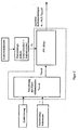
- FIG. 1 a block diagram of the system according to the invention is shown.
- the wheel steering angle signal ⁇ L is determined from the steering angle signal using the gear ratio.
- the wheel steering angle signal ⁇ L is then fed to a smoothing unit, to which the vehicle speed v is supplied as a further input variable.
- the smoothing unit which can also be referred to as a temporal signal filter, is essentially determined by the fitter time constant ⁇ .
- ⁇ L time-smoothing of the wheel steering angle signal ⁇ L , which is also speed-dependent.
- the speed dependence is preferably realized by a speed-dependent filter time constant ⁇ (v).
- FIG. 2 a block diagram of the smoothing unit is shown.
- the smoothing unit in turn consists of two units, namely a first unit for speed-dependent calculation of the filter time constant and the actual filter, the respective current filter time constant is fed to the actual filter, where the smoothing is performed according to the current filter time constant.
- the filter is realized in the illustrated embodiment as a computer-implemented filter algorithm, preferably in the form of a proportional-time filter, which is familiar to the person skilled in the PT1 filter.
- the filter is implemented by an electrical filter circuit (not shown) whose time constant is, for example, an RC element.
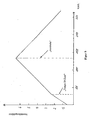
- the filter time constant is constant and relatively small. In these situations, where the driver performs strong steering movements, he expects a fast and immediate Pivoting reaction of the light distribution to the steering movements it performs.
- a limit speed of e.g. 130km / h is preferably a sudden increase in the filter time constant. This can be done, for example, by adding a value. Beyond this limit speed, the filter time constant then increases linearly with the speed. Due to the sudden increase in the filter time constant when the limit speed is exceeded, in particular increased stability is achieved when driving on freeways.
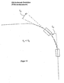
- a further advantageous embodiment of the invention is that the filter time constant is determined not only as a function of the driving speed, but also in dependence on the steering direction. Under steering direction is understood whether the steering angle of the straight ahead position (zero degree) is changed as a reference position when swinging in a curve towards larger angle or vice versa when pivoting back in the direction becomes smaller to the reference position. According to the invention, the filter time constant is then abruptly lowered during reverse pivoting (see FIG. 3 ).
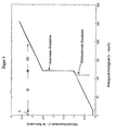
- FIG. 5 the velocity-dependent profile of the amplification factor is shown.
- the amplification factor determines the final value of the swivel angle for a given wheel steering angle, ie the magnitude of the deflection of the light distribution, while the filter time constant determines the dynamics with which the swiveling occurs.
- the gain increases until reaching a limit speed of 130km / h with the speed.
- the filter constant also increases with the velocity. It is precisely this combination that gives the driver the feeling of a safe and physiologically pleasant, pivotable light distribution.
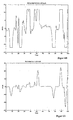
- FIG. 6B shows the inventively determined smoothed and amplified tilt angle signal in response to the time course of the Radlenkwinkelsignals. In this case, the maximum possible swivel angle in the example shown is constructive Limited to ⁇ 12 °.
- FIG. 6C the swing angular velocity (1st time derivative of the swing angle) when activating a filter time constant of 0.7 seconds
- FIG. 6D the swivel angular velocity (1st time derivative of the swivel angle) with a filter time constant of zero (unattenuated) is shown.
- the non-smoothed signal shows significantly more fluctuations that are perceived by both the driver and oncoming traffic as disturbing and physiologically unpleasant.
Landscapes
- Engineering & Computer Science (AREA)
- Mechanical Engineering (AREA)
- Lighting Device Outwards From Vehicle And Optical Signal (AREA)
Claims (10)
- Système de commande d'un dispositif d'éclairage d'un véhicule comprenant :- un moyen de pivotement de la zone éclairée par le dispositif d'éclairage, par rapport à une direction de référence,- un moyen de détermination de l'angle de braquage de roues,- un capteur de vitesse de roulage,- la valeur de consigne pour l'angle de pivotement étant déterminée en fonction de l'angle de braquage de roues,- la valeur de consigne pour l'angle de pivotement étant déterminée en fonction de la vitesse de roulage,- une unité de lissage étant prévue pour le lissage temporel du signal d'angle de braquage de roues,- le lissage se produit en fonction de la vitesse de roulage,- la valeur de consigne pour l'angle de pivotement est déterminée en fonction du signal d'angle de braquage de roues lissé,caractérisé en ce que- le niveau du lissage est déterminé par une constante de temps (τ) de filtre, en fonction de la vitesse,- la constante de temps de filtre est déterminée en fonction de la direction de braquage, la constante de temps de filtre étant abaissée brusquement dans une position de référence, au cours du pivotement en retour de l'angle de braquage de roues.
- Système selon la revendication 1, caractérisé en ce que l'unité de lissage présente un algorithme de filtre mis en oeuvre par ordinateur, comprenant au moins une constante de temps de filtre, le signal d'angle de braquage de roues étant fourni à l'algorithme de filtre, comme une grandeur d'entrée.
- Système selon la revendication 1, caractérisé en ce que l'unité de lissage présente un circuit de filtre électrique comprenant au moins une constante de temps de filtre, le signal de braquage de roues étant fourni au circuit de filtre, comme grandeur d'entrée.
- Système selon l'une quelconque des revendications précédentes, caractérisé en ce qu'il est prévu des constantes de temps de filtre variables pour au moins deux plages de vitesse différentes.
- Système selon la revendication 4, caractérisé en ce que la constante de temps de filtre augmente avec la vitesse, de façon linéaire, dans au moins une plage de vitesse.
- Système selon la revendication 4 ou 5, caractérisé en ce que la constante de temps de filtre se modifie brusquement en cas de dépassement de la valeur supérieure et / ou inférieure d'une vitesse limite.
- Système selon l'une quelconque des revendications précédentes, caractérisé en ce que le signal d'angle de braquage de roues servant à la détermination de la valeur de consigne pour l'angle de pivotement est renforcé en fonction de la vitesse.
- Système selon la revendication 7, caractérisé en ce que le lissage se produit, dans le temps, avant le renforcement, de sorte que le signal d'angle de braquage de roues lissé est renforcé, la valeur de consigne pour l'angle de pivotement correspondant au signal d'angle de braquage de roues lissé en fonction de la vitesse et renforcé.
Applications Claiming Priority (3)
| Application Number | Priority Date | Filing Date | Title |
|---|---|---|---|
| DE2003110905 DE10310905A1 (de) | 2003-03-13 | 2003-03-13 | System zur Ansteuerung einer Fahrzeugbeleuchtungseinrichtung |
| DE10310905 | 2003-03-13 | ||
| PCT/EP2004/002477 WO2004080758A2 (fr) | 2003-03-13 | 2004-03-11 | Systeme pour commander un dispositif d'eclairage de vehicule |
Publications (2)
| Publication Number | Publication Date |
|---|---|
| EP1601552A2 EP1601552A2 (fr) | 2005-12-07 |
| EP1601552B1 true EP1601552B1 (fr) | 2008-08-20 |
Family
ID=32980574
Family Applications (1)
| Application Number | Title | Priority Date | Filing Date |
|---|---|---|---|
| EP04719373A Expired - Lifetime EP1601552B1 (fr) | 2003-03-13 | 2004-03-11 | Systeme pour commander un dispositif d'eclairage de vehicule |
Country Status (3)
| Country | Link |
|---|---|
| EP (1) | EP1601552B1 (fr) |
| DE (2) | DE10310905A1 (fr) |
| WO (1) | WO2004080758A2 (fr) |
Families Citing this family (4)
| Publication number | Priority date | Publication date | Assignee | Title |
|---|---|---|---|---|
| JP4457754B2 (ja) | 2003-08-28 | 2010-04-28 | 株式会社デンソー | 車両用前照灯光軸方向自動調整装置 |
| DE102006020960A1 (de) * | 2006-05-05 | 2007-11-15 | Hella Kgaa Hueck & Co. | Scheinwerfer für Fahrzeuge |
| JP4838213B2 (ja) | 2007-08-27 | 2011-12-14 | 株式会社小糸製作所 | ランプシステム及びランプ偏向制御方法 |
| JP5016516B2 (ja) * | 2008-02-13 | 2012-09-05 | 株式会社小糸製作所 | 車両用ランプ照射方向制御システム |
Family Cites Families (7)
| Publication number | Priority date | Publication date | Assignee | Title |
|---|---|---|---|---|
| JP2950897B2 (ja) * | 1990-03-28 | 1999-09-20 | マツダ株式会社 | 車両用ランプの向き制御装置 |
| JPH10203232A (ja) * | 1997-01-29 | 1998-08-04 | Honda Motor Co Ltd | 車両用前照灯装置 |
| JP2001287587A (ja) * | 2000-04-04 | 2001-10-16 | Nissan Motor Co Ltd | 車両用照明装置 |
| JP3747738B2 (ja) * | 2000-05-23 | 2006-02-22 | 日産自動車株式会社 | 車両用照明装置 |
| DE60120314T2 (de) * | 2000-10-03 | 2007-05-24 | Toyota Jidosha Kabushiki Kaisha, Toyota | Einrichtung zur automatischen Steuerung der optischen Achse von Scheinwerfern in Abhängigkeit von der Winkelstellung des Lenkrads |
| JP2002326534A (ja) * | 2001-05-07 | 2002-11-12 | Koito Mfg Co Ltd | 車両用照明装置 |
| JP2004083003A (ja) * | 2002-06-26 | 2004-03-18 | Denso Corp | 車両用前照灯光軸方向自動調整装置 |
-
2003
- 2003-03-13 DE DE2003110905 patent/DE10310905A1/de not_active Withdrawn
-
2004
- 2004-03-11 DE DE502004007888T patent/DE502004007888D1/de not_active Expired - Lifetime
- 2004-03-11 EP EP04719373A patent/EP1601552B1/fr not_active Expired - Lifetime
- 2004-03-11 WO PCT/EP2004/002477 patent/WO2004080758A2/fr not_active Ceased
Also Published As
| Publication number | Publication date |
|---|---|
| DE10310905A1 (de) | 2004-10-14 |
| DE502004007888D1 (de) | 2008-10-02 |
| WO2004080758A3 (fr) | 2006-01-26 |
| EP1601552A2 (fr) | 2005-12-07 |
| WO2004080758A2 (fr) | 2004-09-23 |
Similar Documents
| Publication | Publication Date | Title |
|---|---|---|
| DE102008057313B4 (de) | Verfahren und Vorrichtung zur Bestimmung eines korrigierenden Lenkmoments | |
| DE19751067B4 (de) | Fahrzeugsteuersystem | |
| DE10141425B4 (de) | Verfahren zur fahrzustandsabhängigen Lenkunterstützung | |
| EP1621449B1 (fr) | Méthode d'adaptation d'un système de guidage à la largeur de la voie | |
| DE102009044269A1 (de) | Lenkassistentenvorrichtung | |
| DE10318389A1 (de) | Elektronische Einpark- und Rangierhilfe für Kraftfahrzeuge | |
| DE19817326A1 (de) | Verfahren zum Verkürzen des Bremsgeweges | |
| WO2001079882A1 (fr) | Procede de regulation de la vitesse d'un vehicule automobile | |
| DE102004033347B4 (de) | Fahrzeugbeleuchtungsvorrichtung | |
| DE102011007016A1 (de) | Rollrichtungsbasiertes Parkassistenzsystem | |
| DE10323975B4 (de) | Kraftfahrzeuglenkung mit einer variablen Lenkübersetzung | |
| DE60112508T2 (de) | Beleuchtungsanordnung für Fahrzeuge | |
| DE2450777A1 (de) | Einrichtung zur steuerung eines messstrahls und/oder eines lichtstrahls bei kraftfahrzeugen | |
| DE19834661B4 (de) | Verfahren und Vorrichtung zur Steuerung einer Bremsanlage | |
| DE102004041415B4 (de) | Einrichtung zur automatischen Einstellung der Richtung der Lichtstrahlachse eines Fahrzeugscheinwerfers | |
| DE112009005113T5 (de) | Fahrzeugbetätigungsgerät | |
| DE102009014392A1 (de) | Lenksystem mit variabler Lenkübersetzung | |
| EP1601552B1 (fr) | Systeme pour commander un dispositif d'eclairage de vehicule | |
| DE102005032847A1 (de) | Blinkschalter für ein Kraftfahrzeug, das einen adaptiven Geschwindigkeitsregler aufweist | |
| DE102010021761B4 (de) | Verfahren und Vorrichtung zur Einstellung von Lenkwinkeln einer Allradlenkung für ein Kraftfahrzeug | |
| EP1078814B1 (fr) | Procédé et dispositif de commande de la distance d'éclairage d'un véhicule | |
| EP1334862B1 (fr) | Procédé pour déterminer la demande de freinage ou de charge d'un conducteur d'un véhicule | |
| EP1112888B1 (fr) | Régulateur de vitesse avec régulation de la distance entre deux véhicules | |
| WO1998034814A1 (fr) | Procede et dispositif pour la regulation de la dynamique longitudinale d'un vehicule | |
| DE102005019487B4 (de) | Personenkraftwagen, umfassend unabhängig voneinander lenkbare Vorder- und Hinterräder |
Legal Events
| Date | Code | Title | Description |
|---|---|---|---|
| PUAI | Public reference made under article 153(3) epc to a published international application that has entered the european phase |
Free format text: ORIGINAL CODE: 0009012 |
|
| 17P | Request for examination filed |
Effective date: 20050716 |
|
| AK | Designated contracting states |
Kind code of ref document: A2 Designated state(s): AT BE BG CH CY CZ DE DK EE ES FI FR GB GR HU IE IT LI LU MC NL PL PT RO SE SI SK TR |
|
| AX | Request for extension of the european patent |
Extension state: AL LT LV MK |
|
| PUAK | Availability of information related to the publication of the international search report |
Free format text: ORIGINAL CODE: 0009015 |
|
| DAX | Request for extension of the european patent (deleted) | ||
| RBV | Designated contracting states (corrected) |
Designated state(s): DE ES FR GB IT SE |
|
| 17Q | First examination report despatched |
Effective date: 20061204 |
|
| GRAP | Despatch of communication of intention to grant a patent |
Free format text: ORIGINAL CODE: EPIDOSNIGR1 |
|
| GRAS | Grant fee paid |
Free format text: ORIGINAL CODE: EPIDOSNIGR3 |
|
| GRAA | (expected) grant |
Free format text: ORIGINAL CODE: 0009210 |
|
| AK | Designated contracting states |
Kind code of ref document: B1 Designated state(s): DE ES FR GB IT SE |
|
| REG | Reference to a national code |
Ref country code: GB Ref legal event code: FG4D Free format text: NOT ENGLISH |
|
| REF | Corresponds to: |
Ref document number: 502004007888 Country of ref document: DE Date of ref document: 20081002 Kind code of ref document: P |
|
| PG25 | Lapsed in a contracting state [announced via postgrant information from national office to epo] |
Ref country code: ES Free format text: LAPSE BECAUSE OF FAILURE TO SUBMIT A TRANSLATION OF THE DESCRIPTION OR TO PAY THE FEE WITHIN THE PRESCRIBED TIME-LIMIT Effective date: 20081201 |
|
| PLBE | No opposition filed within time limit |
Free format text: ORIGINAL CODE: 0009261 |
|
| PGFP | Annual fee paid to national office [announced via postgrant information from national office to epo] |
Ref country code: GB Payment date: 20090311 Year of fee payment: 6 |
|
| 26N | No opposition filed |
Effective date: 20090525 |
|
| PG25 | Lapsed in a contracting state [announced via postgrant information from national office to epo] |
Ref country code: IT Free format text: LAPSE BECAUSE OF FAILURE TO SUBMIT A TRANSLATION OF THE DESCRIPTION OR TO PAY THE FEE WITHIN THE PRESCRIBED TIME-LIMIT Effective date: 20080820 |
|
| PGFP | Annual fee paid to national office [announced via postgrant information from national office to epo] |
Ref country code: FR Payment date: 20090316 Year of fee payment: 6 |
|
| PG25 | Lapsed in a contracting state [announced via postgrant information from national office to epo] |
Ref country code: SE Free format text: LAPSE BECAUSE OF FAILURE TO SUBMIT A TRANSLATION OF THE DESCRIPTION OR TO PAY THE FEE WITHIN THE PRESCRIBED TIME-LIMIT Effective date: 20081120 |
|
| GBPC | Gb: european patent ceased through non-payment of renewal fee |
Effective date: 20100311 |
|
| REG | Reference to a national code |
Ref country code: FR Ref legal event code: ST Effective date: 20101130 |
|
| PG25 | Lapsed in a contracting state [announced via postgrant information from national office to epo] |
Ref country code: FR Free format text: LAPSE BECAUSE OF NON-PAYMENT OF DUE FEES Effective date: 20100331 |
|
| PG25 | Lapsed in a contracting state [announced via postgrant information from national office to epo] |
Ref country code: GB Free format text: LAPSE BECAUSE OF NON-PAYMENT OF DUE FEES Effective date: 20100311 |
|
| REG | Reference to a national code |
Ref country code: DE Ref legal event code: R081 Ref document number: 502004007888 Country of ref document: DE Owner name: HELLA GMBH & CO. KGAA, DE Free format text: FORMER OWNER: HELLA KGAA HUECK & CO., 59557 LIPPSTADT, DE |
|
| REG | Reference to a national code |
Ref country code: DE Ref legal event code: R084 Ref document number: 502004007888 Country of ref document: DE |
|
| PGFP | Annual fee paid to national office [announced via postgrant information from national office to epo] |
Ref country code: DE Payment date: 20220118 Year of fee payment: 19 |
|
| REG | Reference to a national code |
Ref country code: DE Ref legal event code: R119 Ref document number: 502004007888 Country of ref document: DE |
|
| PG25 | Lapsed in a contracting state [announced via postgrant information from national office to epo] |
Ref country code: DE Free format text: LAPSE BECAUSE OF NON-PAYMENT OF DUE FEES Effective date: 20231003 |