EP1601552B1 - System for controlling a vehicle lighting unit - Google Patents
System for controlling a vehicle lighting unit Download PDFInfo
- Publication number
- EP1601552B1 EP1601552B1 EP04719373A EP04719373A EP1601552B1 EP 1601552 B1 EP1601552 B1 EP 1601552B1 EP 04719373 A EP04719373 A EP 04719373A EP 04719373 A EP04719373 A EP 04719373A EP 1601552 B1 EP1601552 B1 EP 1601552B1
- Authority
- EP
- European Patent Office
- Prior art keywords
- speed
- steering angle
- wheel steering
- time constant
- filter time
- Prior art date
- Legal status (The legal status is an assumption and is not a legal conclusion. Google has not performed a legal analysis and makes no representation as to the accuracy of the status listed.)
- Expired - Lifetime
Links
Images


Classifications
-
- B—PERFORMING OPERATIONS; TRANSPORTING
- B60—VEHICLES IN GENERAL
- B60Q—ARRANGEMENT OF SIGNALLING OR LIGHTING DEVICES, THE MOUNTING OR SUPPORTING THEREOF OR CIRCUITS THEREFOR, FOR VEHICLES IN GENERAL
- B60Q1/00—Arrangement of optical signalling or lighting devices, the mounting or supporting thereof or circuits therefor
- B60Q1/02—Arrangement of optical signalling or lighting devices, the mounting or supporting thereof or circuits therefor the devices being primarily intended to illuminate the way ahead or to illuminate other areas of way or environments
- B60Q1/04—Arrangement of optical signalling or lighting devices, the mounting or supporting thereof or circuits therefor the devices being primarily intended to illuminate the way ahead or to illuminate other areas of way or environments the devices being headlights
- B60Q1/18—Arrangement of optical signalling or lighting devices, the mounting or supporting thereof or circuits therefor the devices being primarily intended to illuminate the way ahead or to illuminate other areas of way or environments the devices being headlights being additional front lights
-
- B—PERFORMING OPERATIONS; TRANSPORTING
- B60—VEHICLES IN GENERAL
- B60Q—ARRANGEMENT OF SIGNALLING OR LIGHTING DEVICES, THE MOUNTING OR SUPPORTING THEREOF OR CIRCUITS THEREFOR, FOR VEHICLES IN GENERAL
- B60Q1/00—Arrangement of optical signalling or lighting devices, the mounting or supporting thereof or circuits therefor
- B60Q1/02—Arrangement of optical signalling or lighting devices, the mounting or supporting thereof or circuits therefor the devices being primarily intended to illuminate the way ahead or to illuminate other areas of way or environments
- B60Q1/04—Arrangement of optical signalling or lighting devices, the mounting or supporting thereof or circuits therefor the devices being primarily intended to illuminate the way ahead or to illuminate other areas of way or environments the devices being headlights
- B60Q1/06—Arrangement of optical signalling or lighting devices, the mounting or supporting thereof or circuits therefor the devices being primarily intended to illuminate the way ahead or to illuminate other areas of way or environments the devices being headlights adjustable, e.g. remotely-controlled from inside vehicle
- B60Q1/08—Arrangement of optical signalling or lighting devices, the mounting or supporting thereof or circuits therefor the devices being primarily intended to illuminate the way ahead or to illuminate other areas of way or environments the devices being headlights adjustable, e.g. remotely-controlled from inside vehicle automatically
- B60Q1/12—Arrangement of optical signalling or lighting devices, the mounting or supporting thereof or circuits therefor the devices being primarily intended to illuminate the way ahead or to illuminate other areas of way or environments the devices being headlights adjustable, e.g. remotely-controlled from inside vehicle automatically due to steering position
-
- B—PERFORMING OPERATIONS; TRANSPORTING
- B60—VEHICLES IN GENERAL
- B60Q—ARRANGEMENT OF SIGNALLING OR LIGHTING DEVICES, THE MOUNTING OR SUPPORTING THEREOF OR CIRCUITS THEREFOR, FOR VEHICLES IN GENERAL
- B60Q2300/00—Indexing codes for automatically adjustable headlamps or automatically dimmable headlamps
- B60Q2300/10—Indexing codes relating to particular vehicle conditions
- B60Q2300/11—Linear movements of the vehicle
- B60Q2300/112—Vehicle speed
-
- B—PERFORMING OPERATIONS; TRANSPORTING
- B60—VEHICLES IN GENERAL
- B60Q—ARRANGEMENT OF SIGNALLING OR LIGHTING DEVICES, THE MOUNTING OR SUPPORTING THEREOF OR CIRCUITS THEREFOR, FOR VEHICLES IN GENERAL
- B60Q2300/00—Indexing codes for automatically adjustable headlamps or automatically dimmable headlamps
- B60Q2300/10—Indexing codes relating to particular vehicle conditions
- B60Q2300/12—Steering parameters
- B60Q2300/122—Steering angle
-
- B—PERFORMING OPERATIONS; TRANSPORTING
- B60—VEHICLES IN GENERAL
- B60Q—ARRANGEMENT OF SIGNALLING OR LIGHTING DEVICES, THE MOUNTING OR SUPPORTING THEREOF OR CIRCUITS THEREFOR, FOR VEHICLES IN GENERAL
- B60Q2300/00—Indexing codes for automatically adjustable headlamps or automatically dimmable headlamps
- B60Q2300/10—Indexing codes relating to particular vehicle conditions
- B60Q2300/12—Steering parameters
- B60Q2300/126—Hysteresis behavior based on steering
-
- B—PERFORMING OPERATIONS; TRANSPORTING
- B60—VEHICLES IN GENERAL
- B60Q—ARRANGEMENT OF SIGNALLING OR LIGHTING DEVICES, THE MOUNTING OR SUPPORTING THEREOF OR CIRCUITS THEREFOR, FOR VEHICLES IN GENERAL
- B60Q2300/00—Indexing codes for automatically adjustable headlamps or automatically dimmable headlamps
- B60Q2300/10—Indexing codes relating to particular vehicle conditions
- B60Q2300/12—Steering parameters
- B60Q2300/128—Steering dead zone
Definitions
- the invention relates to a system for controlling a vehicle lighting device with a means for pivoting the area illuminated by the illumination device relative to a reference direction (vehicle longitudinal direction), a means for determining the steering wheel angle and the wheel steering angle and with a vehicle speed sensor.
- a reference direction vehicle longitudinal direction
- the determination of the desired value for the pivot angle of the pivoting means in dependence on the Radlenkwinkel.
- Such a system is also referred to as dynamic cornering light, as it dynamically follows the steering movements of the wheels.
- Such a system is from the EP 1 157 888 A2 known.
- the target value for the swivel angle is equal to the wheel steering angle multiplied by a speed-dependent gain factor.
- the problem with such a system is that even slight, short-term fluctuations of the steering wheel angle ("jitter about the zero position"), which are inevitably always present even at higher speeds, leads to a restless swinging back and forth of the light distribution generated by the lighting device , This is perceived by the driver and also by oncoming traffic as irritating and disturbing.
- the document EP 1 375 250 A2 belongs to the state of the art under Article 54 (3) EPC and applies to the Contracting States DE, GB and FR.
- the document discloses a system for driving a vehicle lighting device comprising means for pivoting the area illuminated by the illumination device relative to a reference direction with a means for determining the wheel steering angle with a pair of speed sensors, wherein the target value for the pivot angle is determined as a function of the wheel steering angle wherein the target value for the swivel angle is determined as a function of the driving speed and wherein a smoothing unit is provided for smoothing the Radlenkwinkelsignals, the smoothing takes place in dependence on the driving speed, the target value for the swivel angle is determined in dependence on the smoothed wire steering angle signal.
- the object of the invention is therefore to provide a system which eliminates the problem described above.
- the wheel steering angle signal is temporally smoothed as the base signal for determining the target value for the swivel angle in a smoothing unit (filter).
- a smoothing unit filter
- the system reacts at higher speeds carrier to steering influences, so that a restless swinging back and forth of the light distribution generated by the lighting device is avoided.
- the smoothing of the Radlenkwinkelsignals according to the invention is additionally speed-dependent, the extent of smoothing at higher speeds compared to lower speeds is greater.
- the wheel steering angle signal as the actual base signal for the determination of the swivel angle desired value can be determined in various ways, for example via a steering angle sensor which determines the steering wheel angle, wherein the wheel steering angle is in a defined, substantially linear transmission ratio to the steering angle.
- the wheel steering angle signal is determined by multiplying the steering angle signal by a gear ratio.
- the wheel steering angle signal can also be determined directly via a Radlenkwinkelsensor.
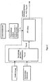
- FIG. 1 a block diagram of the system according to the invention is shown.
- the wheel steering angle signal ⁇ L is determined from the steering angle signal using the gear ratio.
- the wheel steering angle signal ⁇ L is then fed to a smoothing unit, to which the vehicle speed v is supplied as a further input variable.
- the smoothing unit which can also be referred to as a temporal signal filter, is essentially determined by the fitter time constant ⁇ .
- ⁇ L time-smoothing of the wheel steering angle signal ⁇ L , which is also speed-dependent.
- the speed dependence is preferably realized by a speed-dependent filter time constant ⁇ (v).
- FIG. 2 a block diagram of the smoothing unit is shown.
- the smoothing unit in turn consists of two units, namely a first unit for speed-dependent calculation of the filter time constant and the actual filter, the respective current filter time constant is fed to the actual filter, where the smoothing is performed according to the current filter time constant.
- the filter is realized in the illustrated embodiment as a computer-implemented filter algorithm, preferably in the form of a proportional-time filter, which is familiar to the person skilled in the PT1 filter.
- the filter is implemented by an electrical filter circuit (not shown) whose time constant is, for example, an RC element.
- the filter time constant is constant and relatively small. In these situations, where the driver performs strong steering movements, he expects a fast and immediate Pivoting reaction of the light distribution to the steering movements it performs.
- a limit speed of e.g. 130km / h is preferably a sudden increase in the filter time constant. This can be done, for example, by adding a value. Beyond this limit speed, the filter time constant then increases linearly with the speed. Due to the sudden increase in the filter time constant when the limit speed is exceeded, in particular increased stability is achieved when driving on freeways.
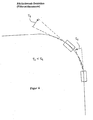
- a further advantageous embodiment of the invention is that the filter time constant is determined not only as a function of the driving speed, but also in dependence on the steering direction. Under steering direction is understood whether the steering angle of the straight ahead position (zero degree) is changed as a reference position when swinging in a curve towards larger angle or vice versa when pivoting back in the direction becomes smaller to the reference position. According to the invention, the filter time constant is then abruptly lowered during reverse pivoting (see FIG. 3 ).
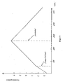
- FIG. 5 the velocity-dependent profile of the amplification factor is shown.
- the amplification factor determines the final value of the swivel angle for a given wheel steering angle, ie the magnitude of the deflection of the light distribution, while the filter time constant determines the dynamics with which the swiveling occurs.
- the gain increases until reaching a limit speed of 130km / h with the speed.
- the filter constant also increases with the velocity. It is precisely this combination that gives the driver the feeling of a safe and physiologically pleasant, pivotable light distribution.
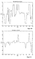
- FIG. 6B shows the inventively determined smoothed and amplified tilt angle signal in response to the time course of the Radlenkwinkelsignals. In this case, the maximum possible swivel angle in the example shown is constructive Limited to ⁇ 12 °.
- FIG. 6C the swing angular velocity (1st time derivative of the swing angle) when activating a filter time constant of 0.7 seconds
- FIG. 6D the swivel angular velocity (1st time derivative of the swivel angle) with a filter time constant of zero (unattenuated) is shown.
- the non-smoothed signal shows significantly more fluctuations that are perceived by both the driver and oncoming traffic as disturbing and physiologically unpleasant.
Landscapes
- Engineering & Computer Science (AREA)
- Mechanical Engineering (AREA)
- Lighting Device Outwards From Vehicle And Optical Signal (AREA)
Description
Die Erfindung bezieht sich auf ein System zur Ansteuerung einer Fahrzeugbeleuchtungseinrichtung mit einem Mittel zum Verschwenken des von der Beleuchtungseinrichtung ausgeleuchteten Bereichs relativ zur einer Referenzrichtung (Fahrzeuglängsrichtung), einem Mittel zur Bestimmung des Lenkradwinkels bzw. des Radlenkwinkels und mit einem Fahrgeschwindigkeitssensor. Dabei erfolgt die Bestimmung des Sollwertes für den Schwenkwinkel des Verschwenkmittels in Abhängigkeit vom Radlenkwinkel. Ein solches System wird auch als dynamisches Kurvenlicht bezeichnet, da es dynamisch den Lenkbewegungen der Räder folgt.The invention relates to a system for controlling a vehicle lighting device with a means for pivoting the area illuminated by the illumination device relative to a reference direction (vehicle longitudinal direction), a means for determining the steering wheel angle and the wheel steering angle and with a vehicle speed sensor. In this case, the determination of the desired value for the pivot angle of the pivoting means in dependence on the Radlenkwinkel. Such a system is also referred to as dynamic cornering light, as it dynamically follows the steering movements of the wheels.
Ein derartiges System ist aus der
Das Dokument
Nachteilig erweist sich hierbei, dass keine geschwindigkeitsabhängige Glättung durchgeführt wird und bei starken Lenkbewegungen keine schnelle und unmittelbare Schwenkreaktion der Lichtverteilung erfolgt.The disadvantage here proves that no speed-dependent smoothing is performed and with strong steering movements no fast and immediate pivotal reaction of the light distribution takes place.
Aufgabe der Erfindung ist es daher, ein System zu schaffen, das die vorstehend beschriebene Problematik beseitigt.The object of the invention is therefore to provide a system which eliminates the problem described above.
Diese Aufgabe wird erfindungsgemäß durch die Merkmale der Anspruch 1 gelöst. Es ist vorteilhaft, daß das Radlenkwinkelsignal als das Basissignal zur Bestimmung des Sollwerts für den Schwenkwinkel in einer Glättungseinheit (Filter) zeitlich geglättet wird. Auf diese Weise kann erreicht werden, daß das System bei höheren Geschwindigkeiten träger auf Lenkeinflüsse reagiert, so daß ein unruhiges Hin- und Herschwenken der von der Beleuchtungseinrichtung erzeugten Lichtverteilung vermieden wird. Die so erzielte, bei hohen Geschwindigkeiten vorteilhafte Trägheit des Systems, die bei hohen Geschwindigkeiten die gewünschte Stabilität der Lichtverteilungslage gegenüber kurzeitig schwankenden Lenkeinflüssen bewirkt, wird andererseits bei niedrigen Geschwindigkeiten (z.B. bei Abbiegemanövern in Wohngebieten) als nachteilig empfunden, da der Fahrer hier eine schnelle und unmittelbare Schwenkreaktion der Lichtverteilung auf die von ihm durchgeführten Lenkbewegungen erwartet. Um diesen Anforderungen gerecht zu werden, erfolgt die Glättung des Radlenkwinkelsignals erfindungsgemäß zusätzlich geschwindigkeitsabhängig, wobei das Ausmaß der Glättung bei höheren Geschwindigkeiten im Vergleich zu niedrigeren Geschwindigkeiten größer ist.This object is achieved by the features of
Das Radlenkwinkelsignal als dem eigentlichen Basissignal für die Bestimmung des Schwenkwinkelsollwertes kann auf verschiedene Weise ermittelt werden, zum Beispiel über einen Lenkwinkelsensor, der den Lenkradwinkel ermittelt, wobei der Radlenkwinkel in einem definierten, im wesentlichen linearen Übersetzungsverhältnis zum Lenkwinkel steht. In diesem Fall wird das Radlenkwinkelsignal durch Multiplikation des Lenkwinkelsignals mit einem Übersetzungsfaktor ermittelt. Das Radlenkwinkelsignal kann jedoch auch unmittelbar über einen Radlenkwinkelsensor ermittelt werden.The wheel steering angle signal as the actual base signal for the determination of the swivel angle desired value can be determined in various ways, for example via a steering angle sensor which determines the steering wheel angle, wherein the wheel steering angle is in a defined, substantially linear transmission ratio to the steering angle. In this case, the wheel steering angle signal is determined by multiplying the steering angle signal by a gear ratio. However, the wheel steering angle signal can also be determined directly via a Radlenkwinkelsensor.
Bei der konstruktiven Ausbildung der Beleuchtungseinrichtung sowie dem Mittel zum Verschwenken der von der Beleuchtungseinrichtung erzeugten Lichtverteilung kommen sämtliche dem Fachmann bekannte Varianten in Verbindung mit der Erfindung in Frage.In the structural design of the illumination device and the means for pivoting the light distribution generated by the illumination device, all variants known to the person skilled in the art come into question in connection with the invention.
Anhand der beigefügten Zeichnungen soll die Erfindung nachfolgend veranschaulicht und näher beschrieben werden. Es zeigt:
Figur 1- eine Blockschaltbild des erfindungsgemäßen Systems,
Figur 2- ein Blockschaltbild der Glättungseinheit,
Figur 3- den geschwindigkeitsabhängigen Verlauf der Filterzeitkonstanten,
Figur 4- das zeitlich unterschiedliche Schwenkverhalten bei der Einfahrt und der Ausfahrt in eine Kurve,
Figur 5- den geschwindigkeitsabhängigen Verlauf des Verstärkungsfaktors,
Figur 6- A einen Zeitverlauf für das Radlenkwinkelsignal,
- Figur 6B
- das geglättete und verstärkte Schwenkwinkelsignal bei 80km/h als Antwort auf den zeitlichen Verlauf des Radlenkwinkelsignals,
- Figur 6C
- die Schwenkwinkelgeschwindigkeit (1. zeitliche Ableitung des Schwenkwinkels) bei Aktivierung einer Filterzeitkonstanten von 0,7 Sekunden,
- Figur 6D
- die Schwenkwinkelgeschwindigkeit (1. zeitliche Ableitung des Schwenkwinkels) bei Aktivierung einer Filterzeitkonstanten von Null (ungedämpft).
- FIG. 1
- a block diagram of the system according to the invention,
- FIG. 2
- a block diagram of the smoothing unit,
- FIG. 3
- the speed-dependent course of the filter time constants,
- FIG. 4
- the temporally different swing behavior at the entrance and the exit into a curve,
- FIG. 5
- the speed-dependent course of the amplification factor,
- FIG. 6
- A is a time course for the wheel steering angle signal,
- FIG. 6B
- the smoothed and amplified swing angle signal at 80km / h in response to the timing of the wheel steering angle signal,
- FIG. 6C
- the swivel angular velocity (1st time derivative of the swivel angle) when activating a filter time constant of 0.7 seconds,
- FIG. 6D
- the swivel angular velocity (1st time derivative of the swivel angle) when activating a filter time constant of zero (undamped).
In
Das geglättete Radlenkwinkelsignal ϕL = ϕL(τ(v)) wird nun anschließend noch einer Verstärkungseinheit zugeführt. Dort wird das geglättete Radlenkwinkelsignal noch zusätzlich verstärkt, wobei der Verstärkungsfaktor k ebenfalls geschwindigkeitsabhängig ist: k = k(v).
Der Sollwert für den Schwenkwinkel ϕs entspricht dann dem geglätteten und verstärkten Radlenkwinkelsignal, was vorzugsweise durch folgenden funktionellen Zusammenhang ausgedrückt wird: ϕs = ϕL (τ(v)) x k(v). The smoothed wheel steering angle signal φ L = φ L (τ (v)) is then subsequently fed to an amplification unit. There, the smoothed Radlenkwinkelsignal is further enhanced, the gain k is also speed-dependent: k = k (v).
The setpoint value for the swivel angle φ s then corresponds to the smoothed and amplified wheel steering angle signal, which is preferably expressed by the following functional relationship: φ s = φ L (τ (v)) x k (v).
In
Dabei ist der Filter in der dargestellten Ausführungsform als computerimplementierter Filteralgorithmus realisiert, vorzugsweise in Form eines Proportional-Zeit-Filters, der dem Fachmann unter PT1-Filter geläufig ist. In einer weiteren Ausführungsform wird der Filter durch eine elektrische Filterschaltung (nicht dargestellt) realisiert, dessen Zeitkonstante zum Beispiel ein RC-Glied ist.In
In this case, the filter is realized in the illustrated embodiment as a computer-implemented filter algorithm, preferably in the form of a proportional-time filter, which is familiar to the person skilled in the PT1 filter. In another embodiment, the filter is implemented by an electrical filter circuit (not shown) whose time constant is, for example, an RC element.
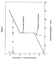
In
- I. Bereich: v ≤ 10km/h
- II. Bereich: 10km/h > v ≥ 130km/h
- III. Bereich: v > 130km/h.
- I. range: v ≤ 10km / h
- II. Range: 10km / h> v ≥ 130km / h
- III. Range: v> 130km / h.
Im ersten Bereich der kleinen Geschwindigkeiten, die typisch für Einpark-, Rangier-und Abbiegesituationen an Kreuzungen (90°-Kurven) sind, ist die Filterzeitkonstante konstant und relativ klein. In diesen Situationen, in denen der Fahrer starke Lenkbewegungen ausführt, erwartet er eine schnelle und unmittelbare Schwenkreaktion der Lichtverteilung auf die von ihm durchgeführten Lenkbewegungen.In the first range of low speeds, which are typical for parking, maneuvering and turning situations at intersections (90 ° curves), the filter time constant is constant and relatively small. In these situations, where the driver performs strong steering movements, he expects a fast and immediate Pivoting reaction of the light distribution to the steering movements it performs.
Im zweiten Bereich bei höheren Geschwindigkeiten werden die vorstehend beschriebenen Einpark-, Rangier- und Abbiegemanöver, die mit sehr starken Lenkbewegungen einhergehen, nicht mehr durchgeführt. In diesem Geschwindigkeitsbereich werden weniger starke Lenkbewegungen durchgeführt, da ein Fahrzeug in diesem Bereich im wesentlichen nur dem Kurvenverlauf der Fahrbahn folgt. Dabei besteht in diesem Geschwindigkeitsbereich im Vergleich zum ersten Bereich ein Großteil aus Geradeausfahrt. Allerdings bewirken insbesondere bei Geradeausfahrt geringfügige, kurzzeitige Schwankungen des Lenkradwinkels, die zwangsläufig immer vorhanden sind, ein als störend und irritierend empfundenes unruhiges Hin- und Herschwenken der von der Beleuchtungseinrichtung erzeugten Lichtverteilung. Dabei werden aufgrund der Reichweite der Lichtverteilung, z.B. beim Abblendlicht, bereits kleinste Schwenkwinkelauslenkungen deutlich wahrgenommen. Zur Glättung dieser störenden Schwenkwinkelschwankungen ist in diesem Geschwindigkeitsbereich im Unterschied zum ersten Bereich eine vorzugsweise linear mit der Geschwindigkeit ansteigende Filterzeitkonstante vorgesehen.In the second range at higher speeds, the parking, maneuvering and turning maneuvers described above, which are associated with very strong steering movements, are no longer performed. In this speed range less strong steering movements are performed because a vehicle in this area essentially follows only the curve of the road. In this speed range, compared to the first area, a large part consists of driving straight ahead. However, in particular when driving straight ahead, slight, short-term fluctuations in the steering wheel angle, which are inevitably always present, cause a disturbing and irritating, uneasy swinging back and forth of the light distribution generated by the lighting device. Thereby, due to the range of the light distribution, e.g. at the low beam, even the smallest Schwenkwinkelauslenkungen clearly perceived. To smooth these disturbing swivel angle fluctuations, in contrast to the first region, a filter time constant that preferably increases linearly with the speed is provided in this speed range.
Beim Überschreiten einer Grenzgeschwindigkeit von z.B. 130km/h erfolgt vorzugsweise ein sprunghafter Anstieg der Filterzeitkonstanten. Dies kann zum Beispiel durch Addition eines Wertes erfolgen. Jenseits dieser Grenzgeschwindigkeit steigt die Filterzeitkonstante dann wiederum linear mit der Geschwindigkeit. Durch den sprunghaften Anstieg der Filterzeitkonstanten bei Überschreitung der Grenzgeschwindigkeit wird insbesondere eine erhöhte Stabilität bei Fahrten auf Autobahnen bewirkt.When exceeding a limit speed of e.g. 130km / h is preferably a sudden increase in the filter time constant. This can be done, for example, by adding a value. Beyond this limit speed, the filter time constant then increases linearly with the speed. Due to the sudden increase in the filter time constant when the limit speed is exceeded, in particular increased stability is achieved when driving on freeways.
Eine weitere vorteilhafte Ausgestaltung der Erfindung besteht darin, daß die Filterzeitkonstante nicht nur in Abhängigkeit von der Fahrgeschwindigkeit, sondern zusätzlich auch in Abhängigkeit von der Lenkrichtung bestimmt wird. Dabei wird unter Lenkrichtung verstanden, ob der Lenkwinkel von der Geradeausstellung (Nullgradstellung) als Referenzposition beim Einschwenken in eine Kurve hin zu größeren Winkel geändert wird oder umgekehrt beim Rückschwenken in Richtung auf die Referenzposition kleiner wird. Erfindungsgemäß wird nun die Filterzeitkonstante beim Rückschwenken sprunghaft erniedrigt (siehe
In
Korrespondierend zum Verstärkungsfaktor steigt auch die Filterkonstante mit der Geschwindigkeit an. Gerade diese Kombination vermittelt dem Fahrer das Gefühl einer sicheren und physiologisch angenehmen schwenkbaren Lichtverteilung.Corresponding to the amplification factor, the filter constant also increases with the velocity. It is precisely this combination that gives the driver the feeling of a safe and physiologically pleasant, pivotable light distribution.
Claims (10)
- System for controlling a lighting apparatus for vehicles- comprising a means of moving the area illuminated by the lighting apparatus with reference to a reference direction,- comprising a means of determining the wheel steering angle,- comprising a vehicle speed sensor,where the nominal swivel angle is determined with reference to the wheel steering angle,
where the nominal swivel angle is determined with reference to the vehicle speed,
characterized in that- a smoothing unit is provided for smoothing the wheel steering angle signal,- smoothing depends on the driving speed,- the nominal swivel angle is determined with reference to the smoothed wheel steering angle signal. - System of claim 1,
characterized in that
the smoothing unit is based around a filtering algorithm implemented by a computer and comprising at least one filter time constant, wherein the wheel steering angle signal is used as the input variable for the filtering algorithm. - System of claim 1,
characterized in that
the smoothing unit is based around an electric filter circuit comprising at least one filter time constant, wherein the wheel steering angle signal is used as the input variable for the filter circuit. - System of one of the above claims,
characterized in that
a speed-dependent filter time constant (τ) is used to determine the amount of smoothing, - System of claim 4,
characterized in that
different filter time constants are provided for at least two different speed ranges. - System of claim 5,
characterized in that
the filter time constant has a linear increase parallel with the speed through at least one speed range. - System of claim 5 or 6,
characterized in that
the filter time constant changes erratically when the speed exceeds or falls below a limit. - System of claims 4 to 7,
characterized in that
the filter time constant is determined with reference to the steering direction such that the filter time constant is quickly reduced when the wheel steering angle returns to a reference position. - System of one of the above claims,
characterized in that
the wheel steering angle signal used to determine the nominal swivel angle is amplified with reference to the speed. - System of claim 9,
characterized in that
smoothing precedes amplification in time such that the smoothed wheel steering angle signal is amplified using a nominal swivel angle equivalent to the wheel steering angle signal that was previously smoothed with reference to the speed and amplified.
Applications Claiming Priority (3)
| Application Number | Priority Date | Filing Date | Title |
|---|---|---|---|
| DE2003110905 DE10310905A1 (en) | 2003-03-13 | 2003-03-13 | System for controlling a vehicle lighting device |
| DE10310905 | 2003-03-13 | ||
| PCT/EP2004/002477 WO2004080758A2 (en) | 2003-03-13 | 2004-03-11 | System for controlling a vehicle lighting unit |
Publications (2)
| Publication Number | Publication Date |
|---|---|
| EP1601552A2 EP1601552A2 (en) | 2005-12-07 |
| EP1601552B1 true EP1601552B1 (en) | 2008-08-20 |
Family
ID=32980574
Family Applications (1)
| Application Number | Title | Priority Date | Filing Date |
|---|---|---|---|
| EP04719373A Expired - Lifetime EP1601552B1 (en) | 2003-03-13 | 2004-03-11 | System for controlling a vehicle lighting unit |
Country Status (3)
| Country | Link |
|---|---|
| EP (1) | EP1601552B1 (en) |
| DE (2) | DE10310905A1 (en) |
| WO (1) | WO2004080758A2 (en) |
Families Citing this family (4)
| Publication number | Priority date | Publication date | Assignee | Title |
|---|---|---|---|---|
| JP4457754B2 (en) | 2003-08-28 | 2010-04-28 | 株式会社デンソー | Automatic headlamp optical axis adjustment device for vehicles |
| DE102006020960A1 (en) * | 2006-05-05 | 2007-11-15 | Hella Kgaa Hueck & Co. | Headlights for vehicles |
| JP4838213B2 (en) | 2007-08-27 | 2011-12-14 | 株式会社小糸製作所 | Ramp system and lamp deflection control method |
| JP5016516B2 (en) * | 2008-02-13 | 2012-09-05 | 株式会社小糸製作所 | Vehicle lamp irradiation direction control system |
Family Cites Families (7)
| Publication number | Priority date | Publication date | Assignee | Title |
|---|---|---|---|---|
| JP2950897B2 (en) * | 1990-03-28 | 1999-09-20 | マツダ株式会社 | Vehicle lamp direction control device |
| JPH10203232A (en) * | 1997-01-29 | 1998-08-04 | Honda Motor Co Ltd | Headlight device for vehicles |
| JP2001287587A (en) * | 2000-04-04 | 2001-10-16 | Nissan Motor Co Ltd | Vehicle lighting system |
| JP3747738B2 (en) * | 2000-05-23 | 2006-02-22 | 日産自動車株式会社 | Vehicle lighting device |
| DE60120314T2 (en) * | 2000-10-03 | 2007-05-24 | Toyota Jidosha Kabushiki Kaisha, Toyota | Device for automatically controlling the optical axis of headlamps in relation to the angular position of the steering wheel |
| JP2002326534A (en) * | 2001-05-07 | 2002-11-12 | Koito Mfg Co Ltd | Lighting system for vehicle |
| JP2004083003A (en) * | 2002-06-26 | 2004-03-18 | Denso Corp | Automatic adjustment of the headlight optical axis direction for vehicles |
-
2003
- 2003-03-13 DE DE2003110905 patent/DE10310905A1/en not_active Withdrawn
-
2004
- 2004-03-11 DE DE502004007888T patent/DE502004007888D1/en not_active Expired - Lifetime
- 2004-03-11 EP EP04719373A patent/EP1601552B1/en not_active Expired - Lifetime
- 2004-03-11 WO PCT/EP2004/002477 patent/WO2004080758A2/en not_active Ceased
Also Published As
| Publication number | Publication date |
|---|---|
| DE10310905A1 (en) | 2004-10-14 |
| DE502004007888D1 (en) | 2008-10-02 |
| WO2004080758A3 (en) | 2006-01-26 |
| EP1601552A2 (en) | 2005-12-07 |
| WO2004080758A2 (en) | 2004-09-23 |
Similar Documents
| Publication | Publication Date | Title |
|---|---|---|
| DE102008057313B4 (en) | Method and device for determining a corrective steering torque | |
| DE19751067B4 (en) | Vehicle control system | |
| DE10141425B4 (en) | Method for driving state-dependent steering assistance | |
| EP1621449B1 (en) | Method for adapting a lane keeping system to the lane width | |
| DE102009044269A1 (en) | Assist Device | |
| DE10318389A1 (en) | Electronic parking and maneuvering aid for motor vehicles | |
| DE19817326A1 (en) | Method of reducing braking distance to enable suitable deceleration in all driving situations | |
| WO2001079882A1 (en) | Method for adjusting the speed of a motor vehicle | |
| DE102004033347B4 (en) | The vehicle lighting device | |
| DE102011007016A1 (en) | Roll direction-based parking assistance system | |
| DE10323975B4 (en) | Motor vehicle steering with a variable steering ratio | |
| DE60112508T2 (en) | Lighting arrangement for vehicles | |
| DE2450777A1 (en) | DEVICE FOR CONTROLLING A MEASURING BEAM AND / OR A LIGHT BEAM IN MOTOR VEHICLES | |
| DE19834661B4 (en) | Method and device for controlling a brake system | |
| DE102004041415B4 (en) | Device for automatically adjusting the direction of the light beam axis of a vehicle headlight | |
| DE112009005113T5 (en) | Vehicle actuator | |
| DE102009014392A1 (en) | Steering system for motor vehicle power steering, has variable steering ratios, where overall gear ratio of one steering angle of steering wheel decreases to wheel lock angle | |
| EP1601552B1 (en) | System for controlling a vehicle lighting unit | |
| DE102005032847A1 (en) | Flasher switch for a motor vehicle having an adaptive cruise control | |
| DE102010021761B4 (en) | Method and device for adjusting steering angles of a four-wheel steering system for a motor vehicle | |
| EP1078814B1 (en) | Method and device for controlling the lighting distance of a vehicle | |
| EP1334862B1 (en) | Method determining drivers bake or load request | |
| EP1112888B1 (en) | Method for adaptive cruise control with regulation of inter-vehicle spacing | |
| WO1998034814A1 (en) | Method and device for regulating the longitudinal dynamics of a vehicle | |
| DE102005019487B4 (en) | Passenger cars comprising independently steerable front and rear wheels |
Legal Events
| Date | Code | Title | Description |
|---|---|---|---|
| PUAI | Public reference made under article 153(3) epc to a published international application that has entered the european phase |
Free format text: ORIGINAL CODE: 0009012 |
|
| 17P | Request for examination filed |
Effective date: 20050716 |
|
| AK | Designated contracting states |
Kind code of ref document: A2 Designated state(s): AT BE BG CH CY CZ DE DK EE ES FI FR GB GR HU IE IT LI LU MC NL PL PT RO SE SI SK TR |
|
| AX | Request for extension of the european patent |
Extension state: AL LT LV MK |
|
| PUAK | Availability of information related to the publication of the international search report |
Free format text: ORIGINAL CODE: 0009015 |
|
| DAX | Request for extension of the european patent (deleted) | ||
| RBV | Designated contracting states (corrected) |
Designated state(s): DE ES FR GB IT SE |
|
| 17Q | First examination report despatched |
Effective date: 20061204 |
|
| GRAP | Despatch of communication of intention to grant a patent |
Free format text: ORIGINAL CODE: EPIDOSNIGR1 |
|
| GRAS | Grant fee paid |
Free format text: ORIGINAL CODE: EPIDOSNIGR3 |
|
| GRAA | (expected) grant |
Free format text: ORIGINAL CODE: 0009210 |
|
| AK | Designated contracting states |
Kind code of ref document: B1 Designated state(s): DE ES FR GB IT SE |
|
| REG | Reference to a national code |
Ref country code: GB Ref legal event code: FG4D Free format text: NOT ENGLISH |
|
| REF | Corresponds to: |
Ref document number: 502004007888 Country of ref document: DE Date of ref document: 20081002 Kind code of ref document: P |
|
| PG25 | Lapsed in a contracting state [announced via postgrant information from national office to epo] |
Ref country code: ES Free format text: LAPSE BECAUSE OF FAILURE TO SUBMIT A TRANSLATION OF THE DESCRIPTION OR TO PAY THE FEE WITHIN THE PRESCRIBED TIME-LIMIT Effective date: 20081201 |
|
| PLBE | No opposition filed within time limit |
Free format text: ORIGINAL CODE: 0009261 |
|
| PGFP | Annual fee paid to national office [announced via postgrant information from national office to epo] |
Ref country code: GB Payment date: 20090311 Year of fee payment: 6 |
|
| 26N | No opposition filed |
Effective date: 20090525 |
|
| PG25 | Lapsed in a contracting state [announced via postgrant information from national office to epo] |
Ref country code: IT Free format text: LAPSE BECAUSE OF FAILURE TO SUBMIT A TRANSLATION OF THE DESCRIPTION OR TO PAY THE FEE WITHIN THE PRESCRIBED TIME-LIMIT Effective date: 20080820 |
|
| PGFP | Annual fee paid to national office [announced via postgrant information from national office to epo] |
Ref country code: FR Payment date: 20090316 Year of fee payment: 6 |
|
| PG25 | Lapsed in a contracting state [announced via postgrant information from national office to epo] |
Ref country code: SE Free format text: LAPSE BECAUSE OF FAILURE TO SUBMIT A TRANSLATION OF THE DESCRIPTION OR TO PAY THE FEE WITHIN THE PRESCRIBED TIME-LIMIT Effective date: 20081120 |
|
| GBPC | Gb: european patent ceased through non-payment of renewal fee |
Effective date: 20100311 |
|
| REG | Reference to a national code |
Ref country code: FR Ref legal event code: ST Effective date: 20101130 |
|
| PG25 | Lapsed in a contracting state [announced via postgrant information from national office to epo] |
Ref country code: FR Free format text: LAPSE BECAUSE OF NON-PAYMENT OF DUE FEES Effective date: 20100331 |
|
| PG25 | Lapsed in a contracting state [announced via postgrant information from national office to epo] |
Ref country code: GB Free format text: LAPSE BECAUSE OF NON-PAYMENT OF DUE FEES Effective date: 20100311 |
|
| REG | Reference to a national code |
Ref country code: DE Ref legal event code: R081 Ref document number: 502004007888 Country of ref document: DE Owner name: HELLA GMBH & CO. KGAA, DE Free format text: FORMER OWNER: HELLA KGAA HUECK & CO., 59557 LIPPSTADT, DE |
|
| REG | Reference to a national code |
Ref country code: DE Ref legal event code: R084 Ref document number: 502004007888 Country of ref document: DE |
|
| PGFP | Annual fee paid to national office [announced via postgrant information from national office to epo] |
Ref country code: DE Payment date: 20220118 Year of fee payment: 19 |
|
| REG | Reference to a national code |
Ref country code: DE Ref legal event code: R119 Ref document number: 502004007888 Country of ref document: DE |
|
| PG25 | Lapsed in a contracting state [announced via postgrant information from national office to epo] |
Ref country code: DE Free format text: LAPSE BECAUSE OF NON-PAYMENT OF DUE FEES Effective date: 20231003 |