EP1601191A2 - Digitaler Verschluss - Google Patents
Digitaler Verschluss Download PDFInfo
- Publication number
- EP1601191A2 EP1601191A2 EP05251034A EP05251034A EP1601191A2 EP 1601191 A2 EP1601191 A2 EP 1601191A2 EP 05251034 A EP05251034 A EP 05251034A EP 05251034 A EP05251034 A EP 05251034A EP 1601191 A2 EP1601191 A2 EP 1601191A2
- Authority
- EP
- European Patent Office
- Prior art keywords
- digital
- shutter
- array
- image
- incoming image
- Prior art date
- Legal status (The legal status is an assumption and is not a legal conclusion. Google has not performed a legal analysis and makes no representation as to the accuracy of the status listed.)
- Withdrawn
Links
- 238000000034 method Methods 0.000 claims abstract description 72
- 230000001131 transforming effect Effects 0.000 claims abstract description 11
- 230000000903 blocking effect Effects 0.000 claims abstract description 4
- 230000015654 memory Effects 0.000 claims description 45
- 239000004973 liquid crystal related substance Substances 0.000 claims description 13
- 230000007774 longterm Effects 0.000 claims description 4
- 239000000463 material Substances 0.000 description 9
- 230000008569 process Effects 0.000 description 5
- 230000005540 biological transmission Effects 0.000 description 3
- 230000000875 corresponding effect Effects 0.000 description 3
- 230000005684 electric field Effects 0.000 description 3
- 208000016339 iris pattern Diseases 0.000 description 3
- 238000003491 array Methods 0.000 description 2
- 230000007787 long-term memory Effects 0.000 description 2
- 238000004519 manufacturing process Methods 0.000 description 2
- 230000004044 response Effects 0.000 description 2
- 230000006403 short-term memory Effects 0.000 description 2
- 230000009471 action Effects 0.000 description 1
- 230000000295 complement effect Effects 0.000 description 1
- 238000010276 construction Methods 0.000 description 1
- 238000001514 detection method Methods 0.000 description 1
- 230000000694 effects Effects 0.000 description 1
- 238000005516 engineering process Methods 0.000 description 1
- 230000006870 function Effects 0.000 description 1
- 230000007246 mechanism Effects 0.000 description 1
- 230000004048 modification Effects 0.000 description 1
- 238000012986 modification Methods 0.000 description 1
- 238000004806 packaging method and process Methods 0.000 description 1
- 230000002085 persistent effect Effects 0.000 description 1
- 230000001960 triggered effect Effects 0.000 description 1
- 230000000007 visual effect Effects 0.000 description 1
Images



Classifications
-
- H—ELECTRICITY
- H04—ELECTRIC COMMUNICATION TECHNIQUE
- H04N—PICTORIAL COMMUNICATION, e.g. TELEVISION
- H04N23/00—Cameras or camera modules comprising electronic image sensors; Control thereof
- H04N23/70—Circuitry for compensating brightness variation in the scene
- H04N23/75—Circuitry for compensating brightness variation in the scene by influencing optical camera components
-
- H—ELECTRICITY
- H04—ELECTRIC COMMUNICATION TECHNIQUE
- H04N—PICTORIAL COMMUNICATION, e.g. TELEVISION
- H04N23/00—Cameras or camera modules comprising electronic image sensors; Control thereof
- H04N23/60—Control of cameras or camera modules
- H04N23/63—Control of cameras or camera modules by using electronic viewfinders
-
- H—ELECTRICITY
- H04—ELECTRIC COMMUNICATION TECHNIQUE
- H04N—PICTORIAL COMMUNICATION, e.g. TELEVISION
- H04N23/00—Cameras or camera modules comprising electronic image sensors; Control thereof
- H04N23/70—Circuitry for compensating brightness variation in the scene
- H04N23/73—Circuitry for compensating brightness variation in the scene by influencing the exposure time
Definitions
- the invention generally relates to cameras and more specifically relates to shutters for digital cameras.
- a digital photo may be exposed properly, without having the image washed out or otherwise lacking in contrast, may be a desirable result.
- this may make a shutter compatible with digital or electronic action useful.
- a shutter would also be compatible with the size and packaging of a digital camera, and may advantageously be designed into manufacture of the digital elements themselves.
- a method and apparatus for a digital shutter is provided.
- the invention is an apparatus.
- the present invention may be understood with reference to various embodiments illustrated as methods, apparatuses, and systems for example.
- the apparatus includes an array of digital image sensor elements.
- the apparatus also includes a digital shutter coupled to the array of digital image sensor elements.
- the apparatus may further include a processor.
- the apparatus may also further include a bus coupled to the processor and coupled to the array of digital image sensor elements and coupled to the digital shutter.
- the apparatus may also include a memory coupled to the bus.
- the apparatus may further include a display coupled to the bus.
- the digital shutter may have an iris format.
- the digital shutter may have a grid format.
- the digital shutter may include an array of digitally controlled elements having transmissive and non-transmissive states.
- the digitally controlled elements may include liquid crystal.
- the apparatus may further include a mechanical shutter coupled to the digital shutter.
- the apparatus may also include an auxiliary digital shutter coupled to the digital shutter.
- the digital shutter may be integrated with the array of digitally controlled elements as a single component. Additionally, in the apparatus, the digital shutter may be a separate component from the array of digitally controlled elements.
- the invention is a digital camera.
- the digital camera includes an array of digital image sensor elements.
- the digital camera also includes a digital shutter coupled to the array of digital image sensor elements.
- the digital camera further includes a processor, a memory, and a display. Additionally, the camera includes a bus coupled to the processor, the array of digital image sensor elements, the digital shutter, the memory and the display.
- the digital shutter may include an array of digitally controlled elements having transmissive and non-transmissive states.
- the camera may include a mechanical shutter coupled to the digital shutter.
- the digital shutter may be integrated with the array of digitally controlled elements as a single component. Similarly, in the digital camera, the digital shutter may be a separate component from the array of digitally controlled elements.
- the invention is a method.
- the method includes exposing an array of digital image sensors to an incoming image.
- the method further includes transforming a digital shutter to a non-transmissive state.
- the digital shutter is interposed between the array of digital image sensors and a source of the incoming image.
- the method may further include capturing a representation of the incoming image within the array of digital image sensors.
- the method may also include transferring the representation of the incoming image to a memory.
- the method may further include transferring the representation of the incoming image within the memory from a short-term portion of the memory to a long-term portion of the memory.
- the method may include reading the representation of the incoming image from the array of digital sensors.
- the method may include transforming a mechanical shutter from a transmissive to a non-transmissive state, with the mechanical shutter interposed between the source of the incoming image and the array of digital image sensors. Moreover, the method may include sighting the source of the incoming image within a viewfinder.
- the digital shutter and the array of digital image sensors may be integrated into a single component.
- the digital shutter may be a first component and the array of digital image sensors may be a second component, with the first component separate from the second component.
- the invention is a method of operating a digital camera.
- the method includes sighting the source of the incoming image within a viewfinder of the digital camera.
- the method also includes exposing an array of digital image sensors to an incoming image.
- the method further includes capturing a representation of the incoming image within the array of digital image sensors.
- the method also includes transforming a digital shutter to a non-transmissive state.
- the digital shutter is interposed between the array of digital image sensors and a source of the incoming image.
- the method also includes reading the representation of the incoming image from the array of digital sensors.
- the method further includes transferring the representation of the incoming image to a memory of the digital camera.
- the invention is an apparatus.
- the apparatus includes means for sensing an incoming image.
- the apparatus also includes means for digitally blocking light from a source of the incoming image.
- the apparatus may further include means for capturing a representation of the incoming image within the means for sensing.
- the apparatus may also include means for storing the representation of the incoming image.
- the apparatus may further include means for viewing the incoming image.
- a method and apparatus for a digital shutter is provided.
- a digital shutter may be incorporated as part of a digital camera, either by attachment of separately manufactured digital sensors and digital shutters, or by manufacture of a combined sensor and shutter array.
- the digital shutter may be formed using electrically controlled material which is alternatively either transmissive or non-transmissive.
- Non-transmissive material may be either absorptive or reflective for example.
- material such as liquid-crystal which has light transmission properties responsive to electrical fields may be used to provide a shutter, for example.
- the invention is an apparatus.
- the apparatus includes an array of digital image sensor elements.
- the apparatus also includes a digital shutter coupled to the array of digital image sensor elements.
- the apparatus may further include a processor.
- the apparatus may also further include a bus coupled to the processor and coupled to the array of digital image sensor elements and coupled to the digital shutter.
- the apparatus may also include a memory coupled to the bus.
- the apparatus may further include a display coupled to the bus.
- the digital shutter may have an iris format.
- the digital shutter may have a grid format.
- the digital shutter may include an array of digitally controlled elements having transmissive and non-transmissive states.
- the digitally controlled elements may include liquid crystal.
- the apparatus may further include a mechanical shutter coupled to the digital shutter.
- the apparatus may also include an auxiliary digital shutter coupled to the digital shutter.
- the digital shutter may be integrated with the array of digitally controlled elements as a single component. Additionally, in the apparatus, the digital shutter may be a separate component from the array of digitally controlled elements.
- the invention is a digital camera.
- the digital camera includes an array of digital image sensor elements.
- the digital camera also includes a digital shutter coupled to the array of digital image sensor elements.
- the digital camera further includes a processor, a memory, and a display. Additionally, the camera includes a bus coupled to the processor, the array of digital image sensor elements, the digital shutter, the memory and the display.
- the digital shutter may include an array of digitally controlled elements having transmissive and non-transmissive states.
- the camera may include a mechanical shutter coupled to the digital shutter.
- the digital shutter may be integrated with the array of digitally controlled elements as a single component. Similarly, in the digital camera, the digital shutter may be a separate component from the array of digitally controlled elements.
- the invention is a method.
- the method includes exposing an array of digital image sensors to an incoming image.
- the method further includes transforming a digital shutter to a non-transmissive state.
- the digital shutter is interposed between the array of digital image sensors and a source of the incoming image.
- the method may further include capturing a representation of the incoming image within the array of digital image sensors.
- the method may also include transferring the representation of the incoming image to a memory.
- the method may further include transferring the representation of the incoming image within the memory from a short-term portion of the memory to a long-term portion of the memory.
- the method may include reading the representation of the incoming image from the array of digital sensors.
- the method may include transforming a mechanical shutter from a transmissive to a non-transmissive state, with the mechanical shutter interposed between the source of the incoming image and the array of digital image sensors. Moreover, the method may include sighting the source of the incoming image within a viewfinder.
- the digital shutter and the array of digital image sensors may be integrated into a single component.
- the digital shutter may be a first component and the array of digital image sensors may be a second component, with the first component separate from the second component.
- the invention is a method of operating a digital camera.
- the method includes sighting the source of the incoming image within a viewfinder of the digital camera.
- the method also includes exposing an array of digital image sensors to an incoming image.
- the method further includes capturing a representation of the incoming image within the array of digital image sensors.
- the method also includes transforming a digital shutter to a non-transmissive state.
- the digital shutter is interposed between the array of digital image sensors and a source of the incoming image.
- the method also includes reading the representation of the incoming image from the array of digital sensors.
- the method further includes transferring the representation of the incoming image to a memory of the digital camera.
- the invention is an apparatus.
- the apparatus includes means for sensing an incoming image.
- the apparatus also includes means for digitally blocking light from a source of the incoming image.
- the apparatus may further include means for capturing a representation of the incoming image within the means for sensing.
- the apparatus may also include means for storing the representation of the incoming image.
- the apparatus may further include means for viewing the incoming image.
- FIG. 1 illustrates an embodiment of an array of pixels which may be used as part of a digital shutter.
- Array 150 is divided into essentially identical elements 155.
- Array 150 is composed of liquid crystal, with each element 155 being an individually controllable element, such as through a grid of electrodes (not shown).
- each element 155 may be switched between transmissive and non-transmissive states, such as in response to a changing electrical field.
- the material of array 150 is necessarily material having a property of being switchable between transmissive and non-transmissive states at a granular level (such as for each element 155).
- the material need not be switchable in response to electric fields if some other switching mechanism is available.
- the material need not be liquid crystal, as other materials will perform a similar function.
- Fig. 2 illustrates an embodiment of an iris which may be used as part of a digital shutter.
- Shutter 230 is again a liquid crystal or similar material. It is composed of segments which make up an iris pattern. However, each segment is a single switchable liquid crystal segment.
- segments 238A, 238B, 238C and 238D are each liquid crystal segments which are individually controllable and collectively form an outer ring of the iris.
- segments 236A, 236B, 236C and 236D each form a second ring of the iris collectively while individually forming controllable liquid crystal segments.
- segments 234A and 234B form a ring collectively, approximately half of which is in each segment.
- centerpiece 232 is another controllable liquid crystal segment which may be considered to form a fourth ring (with an inner diameter of zero).
- FIG. 3 illustrates an embodiment of a multi-layer digital shutter overlaying a digital image sensor.
- Shutter array 350 is composed of a set of individually controllable liquid crystal segments 355, much as in the embodiment illustrated in Fig. 1.
- Shutter 330 is composed of an array of individually controllable liquid crystal segments arranged in the pattern of an iris.
- Pixel array 310 underlays the two shutters 330 and 350, and includes an array of individual image sensors 315.
- shutters 330 and 350 may be used to cut off light to pixel array 310.
- Pixel array 310 may sense an image, and stop sensing in conjunction with cutoff by one of the shutters.
- pixel array 310 may effectively act as a memory for a short period of time, as it may retain the last image formed before one or both of the shutters cut off light from a corresponding object. If each pixel 315 integrates light received over time, then the amount of time since light was received may be factored in to scale the value from such a pixel 315.
- individual elements 355 of the shutter 350 may be turned on or shut off to control light falling on portions of array 310, rather than completely closing shutter 350.
- individual portions of rings or individual rings of shutter 330 may be opened/closed (to transmission) to control exposure.
- patterns of exposure may be used, such that shutter array 350 may act as a shutter that slides from any side or diagonally for example, by programming individual elements 355 to turn off in sequence.
- shutter 330 may close in the manner of an iris by programming rings to turn off in sequence.
- a digital shutter may be combined with a mechanical shutter.
- Fig. 4 illustrates an embodiment of a shutter incorporating both mechanical and digital elements.
- Rails 470 support shutter sections 465A and 465B, which may be actuated (moved) using springs, gears, or other mechanical means (not shown).
- the combination of rails 470 and shutter sections 465A and 465B provide a mechanical shutter.
- digital shutter 430 Aligned with the mechanical shutter is digital shutter 430, here illustrated as an iris pattern shutter, similar to the shutter of Fig. 2.
- This alignment allows for an underlying digital image sensor array to be exposed to light through both a digital and a mechanical shutter.
- Such redundancy may be advantageous for a variety of reasons. For example, leakage from one shutter may be counteracted by blockage from the other shutter. Additionally, one shutter may operate faster than the other shutter.
- the two shutters may be used together in conjunction with a digital image sensor in the process of taking pictures digitally.
- FIG. 5 illustrates an embodiment of a digital camera.
- Camera 500 includes a processor, memory, display, bus, and digital image sensor.
- Processor 510 is coupled to bus 550, along with sensor array 520, memory 530 and display 540.
- Processor 510 controls bus 550 and directly or indirectly controls sensor array 520, memory 530 and display 540.
- Bus 550 allows for transfers of data between the components of camera 500.
- Sensor array 520 includes a digital image sensor array and a digital shutter.
- the digital shutter of sensor array 520 controls light exposure to the digital image sensor array of sensor array 520.
- sensor array 520 is formed of a single integrated component including both the digital image sensor array and the digital shutter.
- the shutter and image sensor arrays may be formed separately.
- the shutter and image sensor arrays are preferably operated cooperatively, too insure that the sensor array captures images as desired.
- sensor array 520 captures images, and then processor 510 supervises transfer of data from sensor array 520 to memory 530 for storage and later retrieval.
- display 540 generally either displays an image as presently detected by sensor array 520 or an image as captured by sensor array 520 and stored in memory 530. Thus, display 540 may be used both as a viewfinder and as a previewer of digital images as stored in memory 530.
- Memory 530 may include short-term and long-term memory, such as RAM and EEPROM memory as may be organized into operating memory and FLASH card memory for example.
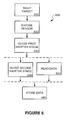
- FIG. 6 illustrates an embodiment of a method of operating a digital camera.
- the method 600 is composed of a set of modules, which may be implemented as steps in a process, process modules, or as apparatus modules performing acts corresponding to the described modules.
- a target object or image is sighted, such as through a viewfinder.
- the sensor array of the camera is exposed to the target object or image, allowing for detection of an image of the target within the sensor array.
- a first shutter stage is closed, such as closing a mechanical shutter exterior to a sensor array.
- a second shutter stage is triggered, such as a digital shutter stage being controlled to stop transmission of light to an adjacent or integrated sensor array.
- data from the digital image sensor portion of a sensor array is read, such as during a transfer of data from a digital image sensor array to a memory module.
- data read from the sensor array is stored, such as in a memory. Storage may relate to transfer from short-term memory to long-term memory, or to reading data from a sensor array and writing that data to memory.
- FIG. 7 illustrates an alternate embodiment of a digital camera.
- Camera 700 includes a processor, image sensor, shutter controller, first and second shutters, a bus, memory, and a display.
- Processor 750 is coupled to bus 780 and to shutter control 740.
- Shutter control 740 is coupled to shutter A 710 and shutter B 720, each of which are aligned between sensor array 730 and any target image or object.
- Shutter control 740 controls shutter A 710 and shutter B 720, triggering each shutter to be either transmissive or non-transmissive.
- Shutter control 740 is, in turn, controlled by processor 750.
- Processor 750 also controls memory 760, sensor array 730 and display 770, each through bus 780.
- Sensor array 730 includes an array of digital image sensors, each of which may capture a pixel of an image when shutter A 710 and shutter B 720 are both in a transmissive mode or state.
- Memory 760 stores the values of sensor array 730, either in temporary storage (such as RAM for example) or in persistent storage (such as FLASH EEPROM for example). Data from sensor array 730 may be transferred along bus 780 to either memory 760 for storage or to display 770 for display (such as for viewfinding applications, for example).
- Display 770 may incorporate a frame buffer, or may use a portion of memory 760 as a frame buffer for example.
- Processor 750 may also be coupled to a user interface (not shown), such as a shooting button and other controls allowing for settings. Moreover, processor 750 may use display 770 as part of the user interface, such as by showing settings or menus on display 770 for example. Processor 750 may thus be expected to control all operations of camera 700.
- a user interface not shown
- processor 750 may use display 770 as part of the user interface, such as by showing settings or menus on display 770 for example. Processor 750 may thus be expected to control all operations of camera 700.
- Shutter A 710 and shutter B 720 may be identical or complementary forms of shutters.
- shutter A 710 may be a mechanical shutter and shutter B 720 may be a digital shutter in the form of either an iris or a grid (array) of digitally controlled elements in some embodiments.
- shutter A 710 and shutter B 720 may both be digital shutters, either identical or variants, such as a combination of a grid and an iris, each with digitally controlled elements, for example.
Landscapes
- Engineering & Computer Science (AREA)
- Multimedia (AREA)
- Signal Processing (AREA)
- Studio Devices (AREA)
- Image Input (AREA)
Applications Claiming Priority (2)
| Application Number | Priority Date | Filing Date | Title |
|---|---|---|---|
| US856270 | 1992-03-23 | ||
| US10/856,270 US20050265714A1 (en) | 2004-05-28 | 2004-05-28 | Digital shutter |
Publications (1)
| Publication Number | Publication Date |
|---|---|
| EP1601191A2 true EP1601191A2 (de) | 2005-11-30 |
Family
ID=34940502
Family Applications (1)
| Application Number | Title | Priority Date | Filing Date |
|---|---|---|---|
| EP05251034A Withdrawn EP1601191A2 (de) | 2004-05-28 | 2005-02-23 | Digitaler Verschluss |
Country Status (4)
| Country | Link |
|---|---|
| US (1) | US20050265714A1 (de) |
| EP (1) | EP1601191A2 (de) |
| CN (1) | CN1702537B (de) |
| TW (1) | TW200538864A (de) |
Cited By (1)
| Publication number | Priority date | Publication date | Assignee | Title |
|---|---|---|---|---|
| EP1944958A3 (de) * | 2007-01-09 | 2009-12-23 | Fujifilm Corporation | Bildaufnahmevorrichtung und Verfahren zur Aufnahme eines Bildes |
Families Citing this family (3)
| Publication number | Priority date | Publication date | Assignee | Title |
|---|---|---|---|---|
| JP2007041119A (ja) * | 2005-08-01 | 2007-02-15 | Olympus Imaging Corp | 撮像装置及び撮像方法 |
| TW200912427A (en) * | 2007-09-05 | 2009-03-16 | Mustek Systems Inc | Diaphragm-shutter mechanism, controlling method thereof, and camera by using the same |
| US10031352B2 (en) * | 2016-03-16 | 2018-07-24 | Sony Corporation | Time and transparency-varying apertures |
Family Cites Families (14)
| Publication number | Priority date | Publication date | Assignee | Title |
|---|---|---|---|---|
| US6005990A (en) * | 1996-06-10 | 1999-12-21 | International Business Machines Corporation | System for optically scanning images using optical shutter |
| EP0785461B1 (de) * | 1997-02-28 | 2003-08-06 | Sinar AG | Stehbildkamera mit wahlweiser photographischer oder elektronischer Bildaufzeichnung |
| KR100246358B1 (ko) * | 1997-09-25 | 2000-03-15 | 김영환 | 전자셔터를 구비한 액티브 픽셀 센서 |
| US6529242B1 (en) * | 1998-03-11 | 2003-03-04 | Micron Technology, Inc. | Look ahead shutter pointer allowing real time exposure control |
| US6809766B1 (en) * | 1998-03-11 | 2004-10-26 | Micro Technology, Inc. | Look ahead rolling shutter system in CMOS sensors |
| US6947077B1 (en) * | 1998-03-30 | 2005-09-20 | Micron Technology, Inc. | Fast and accurate adjustment of gain and exposure time for image sensors |
| KR100280488B1 (ko) * | 1998-06-09 | 2001-02-01 | 김영환 | 전자셔터 기능을 가지는 액티브 픽셀 센서 방식의 픽셀 구조 |
| JP4165220B2 (ja) * | 2000-07-06 | 2008-10-15 | セイコーエプソン株式会社 | 画像処理方法、プログラムおよび画像処理装置 |
| JP2002176588A (ja) * | 2000-12-06 | 2002-06-21 | Canon Inc | 撮像方法及び撮像装置並びに記憶媒体 |
| US6677999B2 (en) * | 2001-07-09 | 2004-01-13 | Hewlett-Packard Development Company, L.P. | Non-polarizing LCD shutter |
| US6956612B2 (en) * | 2001-07-31 | 2005-10-18 | Hewlett-Packard Development Company, L.P. | User selectable focus regions in an image capturing device |
| EP1345428A3 (de) * | 2002-03-11 | 2005-03-16 | Sony Corporation | Verfahren und System zur optischen Intensitätsmodulation, und Apparat zur Modulation des optischen Zustandes |
| JP2004260797A (ja) * | 2003-02-07 | 2004-09-16 | Ricoh Co Ltd | 撮像装置、撮像方法および記録媒体 |
| CN100468181C (zh) * | 2003-04-30 | 2009-03-11 | 佳能株式会社 | 光量调节装置和拍摄装置 |
-
2004
- 2004-05-28 US US10/856,270 patent/US20050265714A1/en not_active Abandoned
-
2005
- 2005-02-16 TW TW094104555A patent/TW200538864A/zh unknown
- 2005-02-23 EP EP05251034A patent/EP1601191A2/de not_active Withdrawn
- 2005-05-27 CN CN2005100745481A patent/CN1702537B/zh not_active Expired - Lifetime
Cited By (2)
| Publication number | Priority date | Publication date | Assignee | Title |
|---|---|---|---|---|
| EP1944958A3 (de) * | 2007-01-09 | 2009-12-23 | Fujifilm Corporation | Bildaufnahmevorrichtung und Verfahren zur Aufnahme eines Bildes |
| US8031255B2 (en) | 2007-01-09 | 2011-10-04 | Fujifilm Corporation | Image capturing device with field limiting parts and method of capturing an image using field limiting parts |
Also Published As
| Publication number | Publication date |
|---|---|
| CN1702537B (zh) | 2012-01-11 |
| CN1702537A (zh) | 2005-11-30 |
| TW200538864A (en) | 2005-12-01 |
| US20050265714A1 (en) | 2005-12-01 |
Similar Documents
| Publication | Publication Date | Title |
|---|---|---|
| RU2608771C2 (ru) | Устройство цифровой фотографии и способ управления им для увеличения скорости непрерывной съемки для захвата панорамных фотографий | |
| US9030590B2 (en) | Photographing apparatus and method | |
| US9172872B2 (en) | Digital photographing apparatus, methods of controlling the same, and computer-readable storage medium to increase success rates in panoramic photography | |
| JP5538549B2 (ja) | ファインダ装置の表示制御方法及びその装置 | |
| CN111050078B (zh) | 一种拍照方法、移动终端及计算机存储介质 | |
| CN101841658B (zh) | 摄像装置及摄像装置的控制方法 | |
| CN103890654B (zh) | 变倍率取景装置及显示信息的亮度变更方法 | |
| KR20130053040A (ko) | 촬상장치 및 촬상방법 | |
| CN105594196B (zh) | 摄像装置和摄像方法 | |
| JP4274665B2 (ja) | 電子ビューファインダ付き電子カメラ | |
| EP1601191A2 (de) | Digitaler Verschluss | |
| CN103685969B (zh) | 摄像装置 | |
| JP2018113724A (ja) | 撮像装置、撮像方法、およびプログラム | |
| KR100726773B1 (ko) | 카메라 및 화상 표시 방법 | |
| JP2004032524A (ja) | デジタルカメラ | |
| JP6410416B2 (ja) | 撮像装置及び撮像装置の制御方法 | |
| US20150049236A1 (en) | View finder device and camera including the same | |
| JP6320251B2 (ja) | 撮像装置、撮像方法、およびプログラム | |
| US20090115873A1 (en) | Method Of Controlling Digital Camera For Testing Pictures, And Digital Camera Using The Method | |
| JP2009077204A (ja) | 画像表示装置を有するカメラ | |
| US8576301B2 (en) | Digital camera having plurality of image recording media and control method for the same | |
| KR20100003639A (ko) | 디지털 영상 처리 장치 | |
| JP4923674B2 (ja) | デジタルカメラ及びフォーカス位置特定方法、プログラム | |
| JP2007129414A (ja) | カメラ | |
| JP2007208406A (ja) | 撮像装置 |
Legal Events
| Date | Code | Title | Description |
|---|---|---|---|
| PUAI | Public reference made under article 153(3) epc to a published international application that has entered the european phase |
Free format text: ORIGINAL CODE: 0009012 |
|
| AK | Designated contracting states |
Kind code of ref document: A2 Designated state(s): AT BE BG CH CY CZ DE DK EE ES FI FR GB GR HU IE IS IT LI LT LU MC NL PL PT RO SE SI SK TR |
|
| AX | Request for extension of the european patent |
Extension state: AL BA HR LV MK YU |
|
| 17P | Request for examination filed |
Effective date: 20051221 |
|
| STAA | Information on the status of an ep patent application or granted ep patent |
Free format text: STATUS: THE APPLICATION IS DEEMED TO BE WITHDRAWN |
|
| 18D | Application deemed to be withdrawn |
Effective date: 20110929 |