EP1601182A2 - Verfahren und Vorrichtung zur Erzeugung von einem Halbtonbild unter Benützung einer Schwellenmatrix für jede Farbkomponente - Google Patents
Verfahren und Vorrichtung zur Erzeugung von einem Halbtonbild unter Benützung einer Schwellenmatrix für jede Farbkomponente Download PDFInfo
- Publication number
- EP1601182A2 EP1601182A2 EP05008406A EP05008406A EP1601182A2 EP 1601182 A2 EP1601182 A2 EP 1601182A2 EP 05008406 A EP05008406 A EP 05008406A EP 05008406 A EP05008406 A EP 05008406A EP 1601182 A2 EP1601182 A2 EP 1601182A2
- Authority
- EP
- European Patent Office
- Prior art keywords
- density
- color component
- base points
- halftone dot
- halftone
- Prior art date
- Legal status (The legal status is an assumption and is not a legal conclusion. Google has not performed a legal analysis and makes no representation as to the accuracy of the status listed.)
- Granted
Links
- 239000011159 matrix material Substances 0.000 title claims abstract description 182
- 238000000034 method Methods 0.000 title claims description 73
- 230000012010 growth Effects 0.000 claims description 11
- 238000011156 evaluation Methods 0.000 description 56
- 238000007639 printing Methods 0.000 description 29
- 238000004364 calculation method Methods 0.000 description 8
- 230000007274 generation of a signal involved in cell-cell signaling Effects 0.000 description 6
- 230000007246 mechanism Effects 0.000 description 6
- 239000003086 colorant Substances 0.000 description 5
- 238000012216 screening Methods 0.000 description 5
- 238000004891 communication Methods 0.000 description 4
- 238000010586 diagram Methods 0.000 description 4
- 238000009826 distribution Methods 0.000 description 4
- 230000015572 biosynthetic process Effects 0.000 description 3
- 230000008859 change Effects 0.000 description 3
- 238000007641 inkjet printing Methods 0.000 description 3
- 230000009467 reduction Effects 0.000 description 3
- 238000000926 separation method Methods 0.000 description 3
- 238000001228 spectrum Methods 0.000 description 3
- 238000003860 storage Methods 0.000 description 3
- 230000014509 gene expression Effects 0.000 description 2
- 230000001788 irregular Effects 0.000 description 2
- 230000003287 optical effect Effects 0.000 description 2
- 230000008569 process Effects 0.000 description 2
- 230000004044 response Effects 0.000 description 2
- 230000001629 suppression Effects 0.000 description 2
- 241000872198 Serjania polyphylla Species 0.000 description 1
- 239000000470 constituent Substances 0.000 description 1
- 230000006866 deterioration Effects 0.000 description 1
- 238000010017 direct printing Methods 0.000 description 1
- 230000000694 effects Effects 0.000 description 1
- 238000005516 engineering process Methods 0.000 description 1
- 230000006870 function Effects 0.000 description 1
- 230000006872 improvement Effects 0.000 description 1
- 238000004519 manufacturing process Methods 0.000 description 1
- 238000012986 modification Methods 0.000 description 1
- 230000004048 modification Effects 0.000 description 1
- 238000005457 optimization Methods 0.000 description 1
- 230000002265 prevention Effects 0.000 description 1
- 238000013519 translation Methods 0.000 description 1
- 230000004304 visual acuity Effects 0.000 description 1
Images







Classifications
-
- H—ELECTRICITY
- H04—ELECTRIC COMMUNICATION TECHNIQUE
- H04N—PICTORIAL COMMUNICATION, e.g. TELEVISION
- H04N1/00—Scanning, transmission or reproduction of documents or the like, e.g. facsimile transmission; Details thereof
- H04N1/40—Picture signal circuits
- H04N1/405—Halftoning, i.e. converting the picture signal of a continuous-tone original into a corresponding signal showing only two levels
- H04N1/4051—Halftoning, i.e. converting the picture signal of a continuous-tone original into a corresponding signal showing only two levels producing a dispersed dots halftone pattern, the dots having substantially the same size
-
- H—ELECTRICITY
- H04—ELECTRIC COMMUNICATION TECHNIQUE
- H04N—PICTORIAL COMMUNICATION, e.g. TELEVISION
- H04N1/00—Scanning, transmission or reproduction of documents or the like, e.g. facsimile transmission; Details thereof
- H04N1/40—Picture signal circuits
- H04N1/405—Halftoning, i.e. converting the picture signal of a continuous-tone original into a corresponding signal showing only two levels
- H04N1/4055—Halftoning, i.e. converting the picture signal of a continuous-tone original into a corresponding signal showing only two levels producing a clustered dots or a size modulated halftone pattern
-
- H—ELECTRICITY
- H04—ELECTRIC COMMUNICATION TECHNIQUE
- H04N—PICTORIAL COMMUNICATION, e.g. TELEVISION
- H04N1/00—Scanning, transmission or reproduction of documents or the like, e.g. facsimile transmission; Details thereof
- H04N1/46—Colour picture communication systems
- H04N1/52—Circuits or arrangements for halftone screening
Definitions
- the present invention relates to a technical field for creating a halftone dot image which represents an original image of gray scale.
- grayscale representation is made by changing the size of dots, instead of changing the number of dots constituting a halftone dot image.
- AM Amplitude Modulated
- FM Frequency Modulated
- grayscale representation is made by changing the number of dots of certain size, which are arranged appropriately (in a random fashion without extreme local difference in density).
- Document 1 grayscale representation is made by changing the size of dots which are arranged in a random fashion.
- the overlapping moire becomes obvious as the difference in arrangement direction of dots is smaller. For example, if the difference in arrangement direction is 15 degrees, a 15 degree moire appears.
- the unnatural nonuniformity such as graininess, printing irregularity, swath patterns or interference moire, which appears in a halftone dot image is liable to become more obvious in color separation of black than in color separations of cyan, magenta and yellow.
- the present invention is intended for a method of generating a threshold matrix which is compared with an original image of gray scale for each color component in creating a halftone dot image which represents the original image, and it is an object of the present invention to easily generate a halftone dot image with less graininess, without causing any moire.
- the method of generating a threshold matrix comprises the steps of a1) arranging a plurality of first base points in a matrix area for a first color component almost in a random fashion at a predetermined density, a2) generating a threshold matrix for the first color component by setting threshold values in the matrix area for the first color component so that dot-like halftone dot areas grow from the plurality of first base points in a halftone dot image in accordance with an increase in gray level of a first original image, b1) arranging a plurality of second base points in a matrix area for a second color component almost in a random fashion at a certain density lower than the predetermined density and higher than half the predetermined density or higher than the predetermined density and lower than twice the predetermined density, and b2) generating a threshold matrix for the second color component by setting threshold values in the matrix area for the second color component so that dot-like halftone dot areas grow from the plurality of second base points in a halftone dot image in accordance with an increase in
- the plurality of second base points are arranged in the matrix area for the second color component at a density not lower than 0.6 times the predetermined density and not higher than 0.9 times or not lower than 1.1 times the predetermined density and not higher than 1.9 times in the step b1).
- the characteristics of spatial frequency of the halftone dot images created from the threshold matrix for the first color component and that of the halftone dot image created from the threshold matrix for the second color component have no portions similar to each other in the frequency space, it is possible to reduce graininess, without causing any moire in a multicolor halftone dot image which is created by superposing these halftone dot images.
- the method further comprises the steps of c1) arranging a plurality of third base points in a matrix area for a third color component almost in a random fashion at a certain density lower than the predetermined density and higher than half the predetermined density or higher than the predetermined density and lower than twice the predetermined density, and c2) generating a threshold matrix for the third color component by setting threshold values in the matrix area for the third color component so that dot-like halftone dot areas grow from the plurality of third base points in a halftone dot image in accordance with an increase in gray level of a third original image, and in the method of the present invention, the density of the plurality of second base points and the density of the plurality of third base points are almost equal to each other, and intervals of the plurality of first base points are isotropic, intervals of the plurality of second base points are smallest in a first direction and intervals of the plurality of third base points are smallest in a second direction different from the first direction.
- the present invention is also intended for a method and an apparatus for creating a halftone dot image using the threshold matrix for each color component generated by the above method, and a recording medium carrying threshold matrixes generated by the above method.
- the present invention is further intended for a method of creating a halftone dot image not depending on whether the threshold matrix is used or not.
- the method comprises the steps of creating a first halftone dot image in which the size of a plurality of dots for a first color component is changed around a plurality of first base points arranged almost in a random fashion at a predetermined density, in accordance with the gray level of a first original image, and creating a second halftone dot image in which the size of a plurality of dots for a second color component is changed around a plurality of second base points arranged almost in a random fashion at a certain density lower than the predetermined density and higher than half the predetermined density or higher than the predetermined density and lower than twice the predetermined density, in accordance with the gray level of a second original image.
- the method comprises the steps of creating a first halftone dot image in which first density in the number of dots for a first color component which are arranged almost uniformly in a random fashion is changed in accordance with the gray level of a first original image, and creating a second halftone dot image in which second density in the number of dots for a second color component which are arranged almost uniformly in a random fashion is changed in accordance with the gray level of a second original image, and in the method of the present invention, the second density is lower than the first density and higher than half the first density or higher than the first density and lower than twice the first density in each gray level.
- the technique for reducing graininess in a multicolor halftone dot image by changing the density in the number of dots by color components can be applied to various methods of creating a halftone dot image in which dots are arranged in a random fashion.
- Fig. 1 is a view showing a constitution of an image recording system 1 in accordance with a preferred embodiment of the present invention.
- the image recording system 1 comprises a computer 11 and an image recording apparatus 12, and the image recording apparatus 12 receives a signal from the computer 11 and records halftone dots on a printing plate serving as a halftone dot recording medium by using light beams from a multichannel laser or the like.
- the image recording apparatus 12 may be a printing apparatus of another recording mode such as an electrophotographic or ink-jet printing apparatus using a photosensitive drum or printing paper as the halftone dot recording medium.
- the computer 11 has a constitution of general computer system where a CPU 101 for performing various computations, a ROM 102 for storing a basic program and a RAM 103 for storing various information are connected to a bus line.
- an image memory 104 for storing data of a grayscale image of a plurality of color components (hereinafter, referred to as "original image") to be represented by halftone dots (screening), a fixed disk 105 for storing information, a display 106 for displaying various information, a keyboard 107a and a mouse 107b for receiving an input from an operator, a reader/writer 108 for reading information from a computer-readable recording medium 91 such as an optical disk, a magnetic disk or a magneto-optic disk and writing information into the recording medium 91, and a communication part 109 for making communications with the image recording apparatus 12 are further connected through an interface (I/F) as appropriate.
- I/F interface
- the image recording apparatus 12 comprises a drum 121 holding a printing plate 8 on its side surface, a writing head 122 for outputting light beams which are modulated in multichannel towards the printing plate 8, a signal generation circuit 123 for generating a signal of halftone dot image to be transmitted to the writing head 122, a driving mechanism for scanning the writing head 122 with respect to the printing plate 8 by rotating the drum 121 and moving the writing head 122 along a rotation axis of the drum 121, and the like.
- pixel refers to one unit for recording (writing) in the image recording apparatus 12 and corresponds to one spot by one light beam.
- a program 92 is read out from the recording medium 91 through the reader/writer 108 in advance and stored in the fixed disk 105. Then, the program 92 is copied in the RAM 103 and the CPU 101 performs a computation according to the program 92 in the RAM 103 (that is, the computer 11 executes the program), by which the computer 11 generates a threshold matrix (also referred to as "SPM (Screen Pattern Memory) data) 710 for each color component to be used for formation of halftone dots, which is discussed later.
- a threshold matrix also referred to as "SPM (Screen Pattern Memory) data
- the threshold matrix 710 and the data of the original image of gray scale stored in the image memory 104 are transmitted to the image recording apparatus 12 through the communication part 109, the signal generation circuit 123 in the image recording apparatus 12 generates a signal of halftone dots for one color component used to represent the original image and the halftone dots are recorded on the printing plate 8 on the basis of the halftone signal while the writing head 122 is scanned with respect to the printing plate 8.
- recording the halftone dots on the printing plate 8 may be regarded as a (physical) formation of the halftone dot image, and generation of the signals for the halftone dots may be regarded as a (nonphysical) formation of the halftone dot image.
- the generation of the signal for the halftone dots may be performed by software with the computer 11 and in this case, the computer 11 solely forms the halftone dot image on the basis of the original image.
- Fig. 2 is a block diagram showing constituent elements of the signal generation circuit 123 in the image recording apparatus 12 and a recording mechanism 120.
- the recording mechanism 120 corresponds to the drum 121, the writing head 122, a mechanism for driving these elements, a circuit for controlling these elements or the like.
- the signal generation circuit 123 comprises an image memory 21 for storing data of the original image of gray scale, an X-address generator 22a and a Y-address generator 22b for generating a subscan address (X address) and a main scan address (Y address) of the original image, respectively, an SPM (Screen Pattern Memory) 23 for storing the threshold matrix 710 generated by the computer 11, an x-address generator 24a and a y-address generator 24b for generating a subscan address (x address) and a main scan address (y address) of the threshold matrix 710, respectively, and a comparator 25.
- an image memory 21 for storing data of the original image of gray scale
- an X-address generator 22a and a Y-address generator 22b for generating a subscan address (X address) and a main scan address (Y address) of the original image, respectively
- an SPM (Screen Pattern Memory) 23 for storing the threshold matrix 710 generated by the
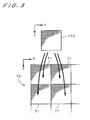
- the original image 70 is divided into a lot of areas having the same size to set repeat areas 71 each serving as a unit for creation of halftone dots.
- the SPM 23 has a storage area for one color component that corresponds to one repeat area 71, and sets a threshold value for each address (coordinates) of the storage area to store the threshold matrix 710. Then, conceptually, the repeat area 71 of the original image 70 and the threshold matrix 710 are superposed and the gray level of each pixel in the repeat area 71 is compared with a corresponding threshold value in the threshold matrix 710, to thereby determine whether writing should be performed on the position of the pixel on the halftone dot recording medium or not.
- the gray level of the original image 70 is uniform, writing is performed on a pixel having an address where a threshold value smaller than the gray level is set in the threshold matrix 710 and macroscopically, uniform halftone dots are generated.
- the threshold matrix 710 is used for creation of the halftone dot image representing the original image of gray scale, through comparison with the original image. The comparison between the threshold matrix 710 and the original image is performed for each color component.
- the gray level (for a specific color component) of one pixel in the original image is read out from the image memory 21 on the basis of an X address and a Y address from the X-address generator 22a and the Y-address generator 22b, respectively.
- an x address and a y address in the repeat area corresponding to the X address and the Y address in the original image are obtained by the x-address generator 24a and the y-address generator 24b, respectively, and one threshold value in the threshold matrix 710 is thereby specified and read out from the SPM 23.
- the comparator 25 compares the gray level from the image memory 21 with the threshold value from the SPM 23, and when the gray level is larger than the threshold value, a signal to indicate that writing should be performed on the position of the pixel is generated.
- a color component specifying signal 81 indicating the color component of the halftone dot image to be recorded is inputted to the image memory 21, and at this time, the threshold matrix 710 to be recorded in the SPM 23 is replaced with one for the specific color component.
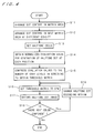
- Fig. 4 is a flowchart showing an operation flow of the image recording system 1.
- the computer 11 sets a matrix area for storing the threshold matrix 710 and centers of halftone cells (each of which is a base point (seed) for generation of the threshold matrix corresponding to the almost central position of a dot used to represent the halftone dot image and hereinafter referred to as "dot center") each serving as a unit of an area for forming the halftone dots are arranged almost uniformly in a random fashion in the matrix area (Step S11).
- Fig. 5 is a view showing the matrix area 720 in which dot centers 721 are arranged. Actually, so many dot centers 721 are arranged in the matrix area 720.
- evaluation values are associated with all the positions (which are specifiable (addressable) by coordinate values) in the matrix area 720 and all the evaluation values are initialized to 0.
- the first dot center 721 is placed at random in the matrix area 720 and the reciprocal of the square of the distance between each position and the first dot center 721 is added to the evaluation value corresponding to the position.
- the matrix area 720 corresponds to the repeat area 71 shown in Fig. 3
- the first dot center 721 which is an object for calculation of the evaluation value is thought to be repeated both in the horizontal and vertical directions.
- in calculation of the evaluation value selected is one out of a plurality of first dot centers 721 when the matrix area 720 is assumed to repeat, which is closest to a position used as a distance calculation reference.
- a second dot center 721 is placed at a position associated with the smallest one of the evaluation values.
- the second dot center 721 is placed at the position farthest from the first dot center 721.
- the reciprocal of the square of the distance between each position and the second dot center 721 (the closest one out of a plurality of second dot centers 721 when the matrix area 720 is assumed to repeat) is added to the corresponding evaluation value.
- a third dot center 721 is placed at a position associated with the smallest evaluation value. If there are a plurality of positions to become a location candidate for the dot center 721, however, one of them is appropriately selected.
- the reciprocal of the square of the distance between each position in the matrix area 720 and the last-placed dot center 721 (assuming that the matrix area 720 is repeated) is added to the corresponding evaluation value, and the next dot center 721 is placed at a position associated with the smallest evaluation value.
- the next dot center 721 is placed at a position farthest from any one of the dot centers 721, and thus the dot centers 721 are arranged almost uniformly in a random fashion.
- the arrangement of the dot centers 721 may be performed by other methods only if the dot centers 721 can be arranged almost uniformly in a random fashion.
- a plurality of dot centers 721 may be arranged as the first dot centers.
- the dot centers 721 which are arranged in a random fashion may be rearranged almost uniformly by utilizing a solution of facility location problem using Voronoi diagrams.
- the facility location problem is a nonlinear optimization problem for determining location of a plurality of facilities in a two-dimensional space so that the total of expenditures to be used by a lot of users who are present in the two-dimensional space to utilize the facilities should become a minimum value.
- the evaluation function used to obtain the "expenditures" is, e.g., a distance between a user and each facility.
- Voronoi diagram is described in detail in "separate volume of "bit”, Computational Geometry and Geographic Information Technology", supervised by Masao Iri, published by Kyoritsu Shuppan Co., Ltd., September 10, 1986, pp. 163 to 168.
- Step S12 the arrangement of the dot centers 721 in the matrix area 720 for one color component is completed, the arrangement of the dot centers 721 in the matrix area 720 for the next color component is performed almost uniformly in a random fashion.
- the arrangement of the dot centers 721 is performed for three color components or more, but the following discussion will be made assuming that the arrangement is performed for two color components and the dot centers 721 for cyan are arranged in Step S11 and those for black are arranged in Step S12.
- the density of the dot centers 721 for black is about 0.7 times that of the dot centers 721 for cyan.
- the halftone dots are recorded by the image recording apparatus 12 having a resolution of 2400 dpi (the width of one pixel is about 10 ⁇ m) under the condition that the screen ruling (halftone dot density) for cyan is 300 and the matrix area 720 has a size of 800 ⁇ 800 pixels, an area allocated to one halftone dot has about 64 (8 ⁇ 8) pixels and in Step S11, the dot centers 721 are added until the number of dot centers 721 which are included in the matrix area 720 becomes 10000.
- the screen ruling halftone dot density
- an area allocated to one halftone dot has about 131 (11.4 ⁇ 11.4) pixels
- the dot centers 721 are added until the number of dot centers 721 which are included in the matrix area 720 becomes 4925. Discussion will be made later on the reason why the density of the dot centers 721 for black is about 0.7 times that of the dot centers 721 for cyan.
- Step S 13 When the arrangement of the dot centers 721 in the matrix area 720 is completed, setting of the halftone cells around the dot centers 721, respectively, each of which serves as a unit for generation of the halftone dot, is performed for each color component (Step S 13).
- Fig. 4 shows the setting of the halftone cells as one step, i.e., Step S 13
- Step S13 is a step collecting a plurality of same steps for a plurality of color components.
- Fig. 6 is a view showing a state where polygonal halftone cells 72 are set around the dot centers 721, respectively, for one color component.
- the halftone cells 72 are set in consideration of repeat of the matrix area 720 both in the horizontal and vertical directions.
- the setting of the halftone cells is performed, for example, in the following manner.
- the evaluation value for one dot center 721 hereinafter, referred to as "specified dot center”
- the matrix area 720 is divided into halftone cells 72 around the dot centers 721.
- Steps S14 and S15 generation of the threshold matrix is further performed by the computer 11 (Steps S14 and S15).
- Generation of the threshold matrix is performed for each color component, and Steps S14 and S 15 in Fig. 4 are steps collecting a plurality of same steps for a plurality of color components.
- a first-stage evaluation value is obtained for each of all the pixels in each halftone cell 72.
- the first-stage evaluation value for example, the distance between the pixel and the dot center 721 of the halftone cell 72 including the pixel or the distance between the pixel and the barycenter of the halftone cell 72 is used.
- Step S 14 If the distance between the pixel and the barycenter of the halftone cell 72 is used as the first-stage evaluation value, it is thought that the dot center 721 should be reset to the barycenter of the halftone cell 72 at this time. Then, numbers of integer which increase by 1 are sequentially assigned to all the pixels in each halftone cell 72, from one having the smallest first-stage evaluation value, and the number is divided by the number of pixels constituting the halftone cell 72, to obtain a second-stage evaluation value (ranging from 0.0 to 1.0) which is normalized by the size of the halftone cell, which is now assigned. This allows a smaller evaluation value to be assigned to a pixel closer to the dot center 721 (or the barycenter of the halftone cell 72) (Step S 14).
- numbers of integer which increase by 1 are sequentially assigned to all the pixels in the matrix area 720, from one having the smallest second-stage evaluation value, and reduction of gray levels is performed in accordance with the number of gray levels in screening (equal to the number of gray levels for each color component in the original image in this preferred embodiment) and the final threshold value is thereby assigned to each pixel, to generate the threshold matrix 710 corresponding to the matrix area 720 (see Fig. 1) (Step S 15).
- the threshold values are set so that the dots should grow around the dot centers 721 in accordance with an increase in gray level of the original image for each color component, and a plurality of threshold matrixes 710 corresponding to a plurality of color components are generated.
- Fig. 7A is a view showing variation in size of the dot (a set of pixels to which writing is performed) to be written in the halftone cell 72 in accordance with variation in gray level of the original image, and areas 72a to 72c represent a dot which grows in accordance with the increase in gray level of the original image.
- the areas 72a to 72c each have a circular shape.
- Figs. 7B and 7C are views showing other exemplary growths of the dot, and the same reference signs as in Fig. 7A are used.
- the first evaluation value in Step S 14 used is a ratio between the distance from the dot center 721 to the pixel which is an object for calculation of the first evaluation value and the distance from the dot center 721 to an edge of the halftone cell 72 on a line connecting the dot center 721 and the pixel.
- an inside polygon formed by connecting midpoints of sides of a polygonal halftone cell is set, and as the first evaluation value used is a ratio between the distance from the dot center 721 to the pixel and the distance from the dot center 721 to an edge of the inside polygon on a line connecting the dot center 721 and the pixel.
- the first evaluation values which increase towards vertices of the halftone cell 72 are appropriately set.
- the threshold values are set so that dot-like halftone dot areas should grow from a plurality of dot centers 721 in a halftone dot image in accordance with the shape of the halftone cell 72 (in other words, within the range of the halftone cell) with an increase in gray level in the original image, and the threshold matrix is thereby generated.
- the threshold matrix 710 for one color component and the data of the original image stored in the image memory 104 are transmitted to the image recording apparatus 12 through the communication part 109 and stored into the SPM 23 and the image memory 21 shown in Fig. 2, respectively, as discussed earlier.
- a group of threshold values corresponding to the growth of the halftone dot of each halftone cell 72 is set in a storage area having the same size as the matrix area 720 in the SPM 23 (Step S16).
- Step S 17 the gray level of each pixel for one color component in the original image stored in the image memory 21 and the corresponding threshold value in the threshold matrix 710 in the SPM 23 are inputted to the comparator 25, the signal generation circuit 123 in the image recording apparatus 12 generates a signal of halftone dot image and the writing head 122 records the halftone dot image of one color component on the printing plate 8 (Step S 17). Specifically, when the gray level of the pixel in the original image is larger than the threshold value, light is emitted to a position of the printing plate 8 corresponding to the pixel by the recording mechanism 120, to thereby perform writing.
- Step S18 If image recording for the next color component is required (Step S18), the image recording medium is replaced with a new one (Step S19), the color specifying signal 81 is inputted to the image memory 21 as shown in Fig. 2, the threshold matrix 710 in the SPM 23 is replaced with one for the next color component and the halftone dot image of the next color component is recorded on the halftone dot recording medium.
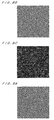
- Figs. 8A to 8C are views showing exemplary halftone dot images which are created in a case (comparison case) where the dot centers 721 are arranged in a random fashion at the same density in the matrix areas 720 for two color components
- Figs. 9A to 9C are views showing exemplary halftone dot images which are created by arranging the dot centers 721 for cyan and black at different densities in the image recording system 1 as discussed earlier.
- Figs. 8A and 9A show the halftone dot images of cyan (in binary representation of white and black) in a case where the gray level of cyan in the original image is uniformly 50 %
- Figs. 8B and 9B show the halftone dot images of black in a case where the gray level of black in the original image is uniformly 50 %
- Fig. 8C shows an image obtained by superposing the images of Figs. 8A and 8B
- Fig. 9C shows an image obtained by superposing the images of Figs. 9A and 9B.
- binary representation of white and black is made. As shown in Fig.
- the characteristic of spatial frequency (spectrum) of the AM halftone dot is represented in a two-dimensional frequency space
- the AM halftone dot since the AM halftone dot has periodicity in a specific direction, there appears a high value representing periodicity in a local area inside the frequency space.
- a local area which appears as the characteristic of spatial frequency of halftone dots for one color component hereinafter, referred to simply as "characteristic of frequency for one color component”
- a local area which appears as the characteristic of frequency for another color component become close to each other.
- these local areas become closer, there arises an unpleasant overlapping moire having longer (lower-frequency) pitch.
- the characteristics of frequency for these color components are closer to each other, there appears more unpleasant moires.
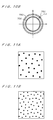
- the density of dot centers 721 for black is about 0.7 times the density of the dot centers 721 for cyan. Therefore, when the characteristics of frequency for these color components are represented in a frequency space, double concentric rings appear as shown in Fig. 10B.
- an outer area 75C corresponds to the halftone dots for cyan having high spatial frequency
- an inner area 75K corresponds to the halftone dots for black having low spatial frequency.
- the color components of halftone dot image include four colors, i.e., cyan, magenta, yellow and black.
- the halftone dot density for black (the density of dots on the highlight side) is about 0.7 times the halftone dot density for other color components.
- the halftone dot density for other color components may be about 0.7 times the halftone dot density for black (in other words, the halftone dot density for black is relatively about 1.3 times the halftone dot density for other color components).
- the halftone dot density for either cyan or magenta is about 0.7 times the halftone dot density for the other color component.
- the size of the dot-like halftone dot area in the same gray level can be made larger for the color component having lower halftone dot density, it is also possible to improve the printing stability and reduce the swath pattern (striped moire appearing in a main scan direction in writing). Therefore, by reducing the halftone dot density for black whose concentration of ink is high, it is possible to improve the printing stability and reduce the swath pattern.
- any one of a plurality of concentric ring-like areas representing the characteristic of spatial frequency for one color component overlaps the ring-like area representing the characteristic of spatial frequency for the other one color component.
- the most preferable changed density of the dot centers 721 is 0.75 times the reference density or 1.5 times. Actually, it is preferable to adopt the changed density which is 0.6 to 0.9 times the reference density or 1.1 to 1.9 times the reference density, and further preferable to adopt the changed density which is 0.7 to 0.8 times the reference density (which corresponds to about 0.7 times in the above discussion) or 1.2 to 1.8 times the reference density.
- the method of changing the density of the dot centers 721 for at least one color component can be also applied to the FM halftone dots.
- grayscale representation is made by changing the number of dots, i.e., the density in the number of dots, instead of changing the size of dot. Therefore, in a case of representing the same gray level, as shown in Figs. 11 A and 11B, by creating the halftone dots having different densities in the number of dots, it is possible to reduce graininess in the multicolor halftone dot image for the same reason discussed referring to Fig. 10B if the original image has a uniform gray level.
- the method of changing the density in the number of dot centers 721 by color components in each gray level can be also applied to halftone dots used to represent gray levels while changing not only the size of dots which grow around the dot centers 721 arranged in a random fashion but also the density in the number of dots (combination of the AM halftone dots and the FM halftone dots), like the FM halftone dots.
- the technique for changing the density in the number of dots for at least one color component can be widely used for various halftone dot images in which the density in the number of dots arranged in a random fashion or (and) the size of dots in accordance with the gray level of the original image, and in creating the halftone dot images, first, a step for creating a first halftone dot image of one color component is performed (which corresponds to the first execution of Steps S16 to S 19 in Fig.
- the density in the number of dots in the second halftone dot image should be lower than the density in the number of dots in the first halftone dot image and higher than half the density or higher than the density in the first halftone dot image and lower than twice the density (preferably, not lower than 0.6 times the density in the first halftone dot image and not higher than 0.9 times the density or not lower than 1.1 times the density in the first halftone dot image and not higher than 1.9 times the density, and more preferably, not lower than 0.7 times the density in the first halftone dot image and not higher than 0.8 times the density or not lower than 1.2 times the density in the first halftone dot image and not higher than 1.8 times the density).
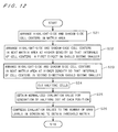
- Fig. 12 is a flowchart showing another operation flow of the image recording system 1.
- This flowchart shows generation of the threshold matrix, which corresponds to Steps S11 to S16 in Fig. 4.
- Fig. 12 shows the operation flow for generation of the threshold matrixes for three color components, and in the operation flow, Steps S21, S22 and S23 are steps corresponding to the operations for these three color components, respectively, and Steps S24 to S26 are steps which are performed commonly for these three color components. Steps S21, S22 and S23 may be performed in this order as shown in Fig. 12 or may be performed in parallel. Steps S24 to S26 may be performed separately or the order of the steps in Fig. 12 may be changed as appropriate within the extent practical.
- Steps S21, S24 to S26 generation of the threshold matrix for one color component (black)
- Steps S22, S24 to S26 and Steps S23, S24 to S26 generation of the threshold matrixes for the other two color components (cyan and magenta)
- a matrix area for storing the threshold matrix 710 for black is set and centers of halftone cells (seeds, hereinafter, referred to as "cell centers") each serving as a unit of an area for forming the halftone dots in the matrix area are regularly arranged.
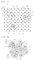
- highlight-side halftone cells whose dot-like halftone dot areas vary in response to variation in highlight-side gray level of the original image (herein, in creating the halftone dots of the original image having a uniform value of pixels, the gray level corresponds to the quantity of the value) and shadow-side halftone cells whose mesh-like halftone dot areas vary in response to variation in shadow-side gray level (in other words, white dots are changed), and in the matrix area 720, as shown in Fig. 13, a plurality of highlight-side cell centers 731 and a plurality of shadow-side cell centers 741 are regularly arranged at the same pitch both in the row direction and the column direction.
- reference points 751 are set in the matrix area 720 almost uniformly in a random fashion by a predetermined method, the number of which are sufficiently smaller than the number of cell centers 731 and 741.
- the matrix area 720 corresponds to the repeat area 71 shown in Fig. 3
- each of the reference points 751 is thought to repeat both in the horizontal and vertical directions.
- the nearest reference point 751 is specified in consideration of repeat of the matrix area 720 with respect to each of the cell centers included in a plurality of highlight-side cell centers 731 and a plurality of shadow-side cell centers 741.
- the computer 11 calculates the distance between each of the cell centers 731 and 741 and the nearest reference point 751 (in consideration of repeat of the matrix area 720). Then, a rotation angle with respect to each of the cell centers 731 and 741 is obtained by a predetermined calculation, and the cell centers 731 and 741 are rotated around the nearest reference point 751 in the same rotating direction, to give fluctuation to the arrangement of the cell centers 731 and 741. At this time, the rotation angle with respect to each of the cell centers 731 and 741 becomes smaller as the distance between the one of the cell centers 731 and 741 and the nearest reference point 751 is longer. In the upper left and lower left areas of Fig.
- shorter arrows 62 which are farther from the reference point 751 indicate that the rotation angle with respect to each of the cell centers 731 and 741 becomes smaller as the distance between the cell center and the nearest reference point 751 is longer.
- arrows 63 conceptually indicate that the rotation angle of each cell center becomes smaller as the distance between the cell center and the reference point 751 is longer.
- the interval of the cell centers 731 and that of the cell centers 741 are each almost isotropic, cell centers 741 are arranged among cell centers 731 and the respective densities are 210 lines (in other words, a pair of cell centers 731 and 741 correspond to one dot center 721 in Fig. 5). Though arrangement of the highlight-side cell centers 731 and that of the shadow-side cell centers 741 are performed at the same time in the above operation, the arrangement of the cell centers 731 and that of the cell centers 741 may be performed separately.
- the above operation is practically a combination of the step of arranging a plurality of highlight-side cell centers 731 which are used as base points for generation of the threshold matrix in the matrix area 720 almost in a random fashion at a predetermined density and the step of arranging a plurality of shadow-side cell centers 741 which are used as interpolation points for the cell centers 731 among the cell centers 731 almost in a random fashion at the same density.
- the highlight-side cell centers 731 and the shadow-side cell centers 741 used is, for example, a method of determining the positions of the highlight-side cell centers 731 like the dot centers 721 in Fig. 5 and then determining the positions of the shadow-side cell centers 741 by moving all the cell centers 731 by half the average value of the distance between the adjacent cell centers 731 in a predetermined direction.
- Step S24 After setting of the cell centers 731 and 741 which are distributed almost uniformly, next, setting of the halftone cells each serving as a unit of creation of the halftone dot in the matrix area 720 around the cell centers 731 and 741 (Step S24).
- the setting of the halftone cells is the same as the case of Fig. 6 except for replacing the dot centers 721 of Fig. 6 with the cell centers 731 and 741.
- FIG. 14 is a view showing a state where the polygonal halftone cells 73 and 74 are set around the cell centers 731 and 741, respectively, and in this figure, the highlight-side halftone cell 73 is set correspondingly to the highlight-side cell center 731 and the shadow-side halftone cell 74 is set correspondingly to the shadow-side cell center 741.
- the halftone cells 73 and 74 are set in the matrix area 720 randomly in an irregular form in consideration of repeat of the matrix area 720 in the horizontal and vertical directions.
- the distance between each of all the positions in the halftone cell 73 or 74 and the cell center 731 or 741 of the halftone cell 73 or 74 including the position is obtained as the first-stage evaluation value.
- numbers of integer which increase by 1 are sequentially assigned to all the positions in the halftone cell 73 or 74, from one having the smallest first-stage evaluation value, and the number is divided by the total number of positions constituting the halftone cell 73 or 74, to obtain the second-stage evaluation value (ranging from 0.0 to 1.0) which is normalized by the size of the halftone cell, which is now assigned. This allows a smaller evaluation value to be assigned to a position closer to the cell center 731 or 741.
- the second-stage evaluation value is changed to a value obtained by subtracting the second-stage evaluation value from 2.
- the normalized second-stage evaluation values each ranging from 0 to 2.0 are assigned to the positions of all the halftone cells (Step S25).
- Fig. 14 showing the halftone cells 73 and 74 in the matrix area 720 also illustrates the change in size of the halftone dot area formed in the halftone cells 73 or 74 in accordance with variation in gray level of the original image, and with the above setting of the threshold values, in the highlight-side halftone cells 73, the dot-like halftone dot areas grow from the cell centers 731 (base points) towards the peripheries in the halftone dot image as indicated by lines 73a to 73c in accordance with an increase in gray level on the highlight side of the original image, and the dots are connected to form a mesh, and in the shadow-side halftone cells 74, the halftone dot area grows from the peripheries towards the cell centers 741 (interpolation points) (the white dots are degenerated) as indicated by lines 74a to 74c in accordance with an increase in gray level on the shadow side of the original image.
- the highlight-side cell center 731 is a center of a dot which grows when the gray level on the highlight side increases, however, it is thought to correspond to the dot center 721 in Fig. 6, and the density of the dot center 721 and that of the cell center 731 are equal to each other in the same screen ruling.
- the shape of boundary of the halftone dot area is not limited to a circle but may be a shape in conformance with the shape of the halftone dot area shown in Fig. 7B or 7C.
- the highlight-side cell centers 731 and the shadow-side cell centers 741 are arranged alternately in two directions, i.e., D1 (a first direction) and D2 (a second direction), which are orthogonal to each other as shown in Fig. 15.
- the cell centers 731 and 741 are arranged in a right-upward direction (a counterclockwise direction at an angle of 45 degrees from the right-horizontal direction) indicated by the arrow D1 of Fig.
- Fig. 16 is a view showing a specific case where the cell centers 731 and 741 are arranged in the matrix area 720.
- the number of positions set in the matrix area 720 (the positions correspond to pixels in the halftone dot image and hereinafter, the number is referred to also as "the number of pixels") is 1131 within a range defined by reference numeral 81 in Fig.
- reference points 751 are arranged in the matrix area 720 almost uniformly in a random fashion, the number of which are sufficiently smaller than the number of cell centers 731 and 741 arranged in the direction D2, and the nearest reference point 751 is specified in consideration of repeat of the matrix area 720 with respect to each of the cell centers.
- the cell centers 731 and 741 are rotated around the nearest reference point 751 in the same rotating direction, and the rotation angle with respect to each of the cell centers 731 and 741 becomes smaller as the distance between the one of the cell centers 731 and 741 and the nearest reference point 751 is longer.
- a plurality of cell centers 731 are arranged in the matrix area 720 almost uniformly in a random fashion so that an average of intervals of the cell centers 731 should become smallest in the direction D1 and become largest in the direction D2 orthogonal to the direction D 1.
- a plurality of cell centers 741 are also arranged in the same manner (Step S22).
- the intervals of the cell centers 731 and those of the cell centers 741 each have directivity (anisotropic property), and cell centers 741 are arranged among the cell centers 731 and the respective densities are 300 lines.
- the arrangement of the cell centers 731 and that of the cell centers 741 may be performed separately, and the above operation is practically a combination of the step of arranging a plurality of highlight-side cell centers 731 which are used as base points for generation of the threshold matrix in the matrix area 720 almost in a random fashion at a density higher than that for black and the step of arranging a plurality of shadow-side cell centers 741 which are used as interpolation points for the cell centers 731 among the cell centers 731 almost in a random fashion at the same density.
- Step S24 After setting of the cell centers 731 and 741 which are distributed almost uniformly with directivity, setting of the halftone cells 73 and 74 around the cell centers 731 and 741 by the same method as the case for black (Step S24). Since the cell centers 731 and 741 are arranged in the direction D1 more densely than in the direction D2, the highlight-side and shadow-side halftone cells 73 and 74 each have a shape which is flatter in the direction D1, in other words, elongated in the direction D2 as shown in Fig. 17.
- the distance (vector) between each of all the positions in the halftone cell 73 or 74 and the cell center 731 or 741 of the halftone cell 73 or 74 including the position is multiplied by 2 in the direction D1 to obtain the first-stage evaluation value.
- numbers of integer which increase by 1 are sequentially assigned to all the positions in the halftone cell 73 or 74, from one having the smallest first-stage evaluation value, and the number is divided by the total number of positions constituting the halftone cell 73 or 74, to obtain the second-stage evaluation value (ranging from 0.0 to 1.0) which is normalized by the size of the halftone cell, which is now assigned.
- This allows almost equal second-stage evaluation values to be present in a shape of ellipse as shown in Fig. 17, and a smaller evaluation value to be assigned to a position closer to the cell center 731 or 741.
- the second-stage evaluation value is changed to a value obtained by subtracting the second-stage evaluation value from 2, and the normalized second-stage evaluation values each ranging from 0 to 2.0 are assigned to the positions of all the halftone cells (Step S25). Then, numbers of integer which increase by 1 are sequentially assigned all the positions in the matrix area 720, from one having the smallest second-stage evaluation value, and the numbers of order each of which is changed to a value within a range from 0 to (N-1) are assigned to all the positions as threshold values (Step S26).
- Fig. 17 also illustrates the change in size of the halftone dot area formed in the halftone cells 73 or 74 in accordance with variation in gray level of the original image, and with the above setting of the threshold values, in the highlight-side halftone cells 73, the dot-like elliptical halftone dot areas grow from the cell centers 731 (base points) towards the peripheries in the halftone dot image as indicated by lines 73a to 73c in accordance with an increase in gray level on the highlight side of the original image, and the dots are connected to form a mesh, and in the shadow-side halftone cells 74, the halftone dot area grows from the peripheries towards the cell centers 741 (interpolation points) (the white elliptical dots are degenerated) as indicated by lines 74a to 74c in accordance with an increase in gray level on the shadow side of the original image.
- each halftone dot area varies in accordance with the shape of the halftone cells
- the highlight-side cell centers 731 and the shadow-side cell centers 741 are arranged alternately in two directions, i.e., D1 and D2 which are orthogonal to each other.
- the cell centers 731 and 741 are arranged in a left-upward direction indicated by the arrow D2 at certain intervals shorter than the intervals (half the intervals) in a right-upward direction indicated by the arrow D1, and the density of the cell centers 731 is set so that the screen ruling should be 300 lines, like in the case of cyan.
- the cell centers for magenta are arranged in such a manner that the arrangement of the cell centers for cyan is rotated at an angle of 90 degrees.
- Step S23 With the above operation, the intervals of the cell centers 731 and those of the cell centers 741 each have directivity different from that for cyan by 90 degrees, and cell centers 741 are arranged among the cell centers 731 and the respective densities are 300 lines.
- the arrangement of the cell centers 731 and that of the cell centers 741 may be performed separately, and the above operation is practically a combination of the step of arranging a plurality of highlight-side cell centers 731 which are used as base points for generation of the threshold matrix in the matrix area 720 almost in a random fashion at a density higher than that for black and the step of arranging a plurality of shadow-side cell centers 741 which are used as interpolation points for the cell centers 731 among the cell centers 731 almost in a random fashion at the same density.
- Step S24 After setting of the cell centers 731 and 741 which are distributed almost uniformly with directivity, setting of the halftone cells 73 and 74 around the cell centers 731 and 741 by the same method as the case for cyan (Step S24). Since the cell centers 731 and 741 are arranged in the direction D2 more densely than in the direction D1, the highlight-side and shadow-side halftone cells 73 and 74 each have a shape which is flatter in the direction D2, in other words, elongated in the direction D 1.
- the distance (vector) between each of all the positions in the halftone cell 73 or 74 and the cell center 731 or 741 of the halftone cell 73 or 74 including the position is multiplied by 2 in the direction D2 to obtain the first-stage evaluation value, and the first-stage evaluation value is normalized to obtain the second-stage evaluation value (ranging from 0.0 to 1.0), which is assigned to each of all the positions.
- This allows almost equal second-stage evaluation values to be present in a shape of ellipse like a reversed case of Fig. 17, and a smaller evaluation value to be assigned to a position closer to the cell center 731 or 741.
- the second-stage evaluation value is changed to a value obtained by subtracting the second-stage evaluation value from 2, and the normalized second-stage evaluation values are assigned to the positions of all the halftone cells (Step S25). Then, the numbers of order each of which is changed to a value within a range from 0 to (N-1) are assigned to all the positions in the matrix area 720 as threshold values (Step S26).
- the dot-like elliptical halftone dot areas grow from the cell centers 731 (base points) towards the peripheries in the halftone dot image in accordance with an increase in gray level on the highlight side of the original image, and the dots are connected to form a mesh
- the halftone dot area grows from the peripheries towards the cell centers 741 (interpolation points) (the white elliptical dots are degenerated) in accordance with an increase in gray level on the shadow side of the original image.
- each halftone dot area varies in accordance with the shape of the halftone cells 73 or 74 with variation in gray level.
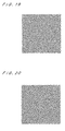
- Figs. 19 and 20 are views showing halftone tint images each having a uniform gray level of 30 %, which are generated by using the threshold matrixes for cyan and magenta, respectively.
- the dots are elongated in a left-upward direction (direction D2), and as shown in Fig. 20, in the halftone tint image of magenta, the dots are elongated in a right-upward direction (direction D1).
- the density of a plurality of cell centers 731 in the halftone tint image of cyan and that of a plurality of cell centers 731 in the halftone tint image of magenta are almost equal to each other.
- the intervals of a plurality of cell centers 731 are smallest in the direction D1 and the growth of a plurality of dots in accordance with an increase in gray level is smallest in the direction D1.
- the intervals of a plurality of cell centers 731 are smallest in the direction D2 and the growth of a plurality of dots in accordance with an increase in gray level is smallest in the direction D2.
- the intervals of a plurality of cell centers 731 for black has almost isotropic property
- the halftone dot density is 0.7 times that of cyan and magenta and the growth of a plurality of dots in accordance with an increase in gray level also has almost isotropic property.
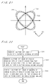
- reference numeral 761 represents the characteristic of spatial frequency (spectrum) of the halftone dot image of cyan and reference numeral 762 represents the characteristic of spatial frequency of the halftone dot image of magenta.
- reference numeral 761 represents the characteristic of spatial frequency (spectrum) of the halftone dot image of cyan
- reference numeral 762 represents the characteristic of spatial frequency of the halftone dot image of magenta.
- the threshold matrix for magenta since the cell centers 731 and 741 are arranged at smaller intervals in the direction D2 and at larger intervals in the direction D1, higher values indicating periodicity are distributed in the elliptical ring-like area 762 which is elongated in the direction D2 in the frequency space.
- the directions where the respective periodicities approximate to each other in the halftone dot images of cyan and magenta are limited to intersections of the areas 761 and 762, and it is therefore possible to suppress an unpleasant low-frequency moire causing graininess in an image obtained by superposing the two halftone dot images.
- the halftone dot image of black since it has almost isotropic property at low screen ruling, the characteristic of frequency appears in a small annular shape as indicated by the broken line 763 in Fig. 21.
- the density of the cell centers 731 (and cell centers 741) for black is different from both that of the cell centers 731 (and cell centers 741) for cyan and that of the cell centers 731 (and cell centers 741) for magenta, and this allows suppression of the graininess caused in the image obtained by superposing the halftone dot image of black and the halftone dot images of the other color components.
- the direction where the intervals of the cell centers 731 for cyan are smaller is different from the direction where the intervals of the cell centers 731 for magenta are smaller, and this allows suppression of the graininess caused in the image obtained by superposing the halftone dot image of cyan and the halftone dot image of magenta. Thus, it is possible to suppress the graininess caused in the image obtained by superposing three colors.
- the density of the cell centers 731 for black may be other than one that is 0.7 times the density of the cell centers 731 for cyan and magenta but, like in the case of Fig. 4, the density may be lower than the density for cyan and magenta and higher than half the density or higher than the density for cyan and magenta and lower than twice the density (preferably, not lower than 0.6 times the density for cyan and magenta and not higher than 0.9 times or not lower than 1.1 times the density for cyan and magenta and not higher than 1.9 times, more preferably, not lower than 0.7 times the density for cyan and magenta and not higher than 0.8 times or not lower than 1.2 times the density for cyan and magenta and not higher than 1.8 times).
- the density of the cell centers 731 for cyan and that for magenta are not necessarily equal to each other perfectly. Since it is not preferable that the densities for cyan and magenta should be greatly different from the density of the cell centers 731 for black, however, in an actual case, the densities of the cell centers 731 for cyan and magenta are made almost equal (so that the difference should not be higher than 30 %).
- the density of the cell centers 731 for black should be made lower than the density of the cell centers 731 for other color components (in other words, the density of the cell centers 731 for other color components should be higher than the density of the cell centers 731 for black and lower than the twice the density), and it is thereby possible to effectively suppress the graininess.
- Fig. 22 is a flowchart showing an operation flow for creation of such an FM halftone dot image, and in this procedure, the halftone dot images of black, cyan and magenta are created in this order (Steps S31 to S33).
- the halftone dot image created for black is the same as shown in Fig. 11B.
- Actually created is the halftone dot image of black in which the density in the number of dots arranged almost uniformly in a random fashion is changed in accordance with the gray level of the original image. In this case, the intervals of dots have almost isotropic property (Step S31).
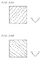
- Fig. 23A is a view showing a halftone dot image created for cyan when the original image has a predetermined uniform gray level.
- created is the halftone dot image of cyan in which the density in the number of dots arranged almost uniformly in a random fashion is changed in accordance with the gray level of the original image.
- the dots are arranged so that the density in the number of dots should be 1.3 times the density in the number of dots in the halftone dot image of black and the intervals of dots should be smallest in the direction D1 (the first direction) in Fig. 23A and largest in the direction D2 (the second direction) orthogonal to the direction D1 (Step S32).
- Fig. 23B is a view showing a halftone dot image created for magenta when the original image has a predetermined uniform gray level.
- the halftone dot image of magenta in which the density in the number of dots arranged almost uniformly in a random fashion is changed in accordance with the gray level of the original image.
- the dots are arranged so that the density in the number of dots should be 1.3 times the density in the number of dots in the halftone dot image of black and the intervals of dots should be smallest in the D2 in Fig. 23B and largest in the direction D1 (Step S33).
- the density in the number of dots for cyan and that for magenta are not necessarily equal to each other perfectly, however, in an actual case, these densities are made almost equal (so that the difference should not be higher than 30 %).
- the density in the number of dots for one color component is lower than the density for other color components and higher than half the density or higher than the density for other color components and lower than twice the density (preferably, not lower than 0.6 times the density for other color components and not higher than 0.9 times or not lower than 1.1 times the density for other color components and not higher than 1.9 times, more preferably, not lower than 0.7 times the density for other color components and not higher than 0.8 times or not lower than 1.2 times the density for other color components and not higher than 1.8 times), and particularly, it is preferable that the density in the number of dots for black should be lower than the density in the number of dots for other color components.
- the method of changing the density in the number of dot centers by color components in each gray level or arranging the dots with different anisotropic properties by color components can be also applied to halftone dots used to represent gray levels while changing not only the size of dots which grow around the dot centers (or cell centers) arranged in a random fashion but also the density in the number of dots (combination of the AM halftone dots and the FM halftone dots), like the FM halftone dots.
- the halftone cells are set in the matrix area and the threshold values are set in accordance with the shape of the halftone cell in the procedures of Figs. 4 and 12, it is not necessary to explicitly perform the setting of the halftone cells.
- dot centers which correspond to the dot centers 721 or the cell centers 731 in the above discussion and serve as base points for determination of the threshold values
- the threshold values are set so that dot-like halftone dot areas should grow from a plurality of dot centers in a halftone dot image in accordance with an increase in gray level of the original image.
- the dot centers 721 are arranged in the matrix area and the halftone dot areas grow from the dot centers 721 in accordance with an increase in gray level of the original image in Fig. 4 and the highlight-side cell centers 731 and the shadow-side cell centers 741 are arranged in the matrix area and the halftone dot areas grow from the cell centers 731 in accordance with an increase in gray level of the original image and the halftone dot areas increase towards the cell centers 741 in Fig. 12, the method of arranging the highlight-side and shadow-side cell centers for generation of a threshold matrix for each color component (Fig. 12: Steps S21, S24 to S26) may be adopted in the case of Fig.
- Steps S11, S13 to S15 may be adopted in the case of Fig. 12.
- the method using the dot centers 721 has a merit of less amount of computation and the method of using two kinds of cell centers 731 and 741 has a merit of achieving symmetric change of the halftone dots on the highlight side and the shadow side.
- the halftone dot image may be created, pursuant to the operation flow of Fig. 22 for generation of the FM halftone dot image, without generation of the threshold matrix, or without using the concept of the threshold matrix regardless of the presence or absence of the threshold matrix. In this case, creation of the halftone dot image in the operation of Fig.
- step 4 is actually a combination of the step of creating a first halftone dot image in which the size of a plurality of dots for a first color component is changed around the first base points which correspond to the dot centers 721 arranged almost in a random fashion at a predetermined density in accordance with the gray level of the original image and the step of creating a second halftone dot image in which the size of a plurality of dots for a second color component is changed around the second base points which correspond to the dot centers 721 arranged almost in a random fashion at a density lower than the density of the first base points and higher half the density or higher than the density of the first base points and lower than twice the density (preferably, higher than 0.6 times the density of the first base points and lower than 0.9 times or higher than 1.1 times the density of the first base points and lower than 1.9 times) in accordance with the gray level of the original image.
- creation of the halftone dot image in the operation of Fig. 11 actually corresponds to a process where the dot centers 721 are replaced with the cell centers 731 in the above combination and to the combination step added is the step of creating a third halftone dot image in which the size of a plurality of dots for a third color component is changed around the third base points which correspond to the cell centers 731 arranged almost in a random fashion at a density lower than the density of the first base points and higher half the density or higher than the density of the first base points and lower than twice the density (preferably, higher than 0.6 times the density of the first base points and lower than 0.9 times or higher than 1.1 times the density of the first base points and lower than 1.9 times) in accordance with the gray level of the original image.
- the process of creating the halftone dot image corresponds to the operation of Fig. 12, where the creation is performed so that the density of a plurality of second base points and the density of a plurality of third base points should be almost equal to each other, the intervals of a plurality of first base points should have almost isotropic property, the growth of a plurality of dots for the first color component in accordance with an increase of gray level should have almost isotropic property, the intervals of a plurality of second base points should be smallest in the direction D1, the growth of a plurality of dots for the second color component in accordance with an increase of gray level should be smallest in the direction D1, the intervals of a plurality of third base points should be smallest in the direction D2, and the growth of a plurality of dots for the third color component in accordance with an increase of gray level should be smallest in the direction D2.
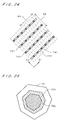
- Initial arrangement of the highlight-side cell centers 731 and the shadow-side cell centers 741 shown in Figs. 15 and 18 may be changed as appropriate, and for example, as shown in Fig. 24, the density of the cell centers in the direction D1 may be three times the density in the direction D2.
- the directions where the intervals of the cell centers for two color components are shorter should be different from each other at an angle of 90 degrees in order to reduce the degree of overlap of spectra for the two color components as shown in Fig. 21, the angle is not necessarily limited to 90 degrees but it is important that the directivities for the two color components should be different.
- the creation of the halftone dot image may be performed by software only with the computer 11 as discussed earlier and further, only the generation of the threshold matrixes 710 may be performed separately by software.
- the reader/writer 108 of Fig. 1 transmits the data of the threshold matrixes 710 to the image recording apparatus 12 through the computer-readable recording medium 91 such as an optical disk or a magnetic disk, or a computer network.
- the image recording apparatus 12 may be an electrophotographic printing apparatus which records halftone dots on a photosensitive drum while scanning multichannel light beams with respect to the photosensitive drum and prints the halftone dots on printing paper, or an ink-jet printing apparatus which records halftone dots on printing paper while scanning multichannel ink-jet nozzles with respect to the printing paper.
- the photosensitive drum or the printing paper serves as a halftone dot recording medium.
- the technique for generation of the threshold matrixes 710 by changing the density of the dot centers 721 for at least one color component can be used in the ink-jet printing apparatus or a direct printing apparatus which records a multivalued halftone dot image other than the binary halftone dot image.
- a plurality of threshold matrixes having similar distributions and different average values of threshold values are obtained for each color component and the gray level of each pixel in the original image is compared with a plurality of threshold values from a plurality of threshold matrixes, to thereby determine which concentration (or color density) to be adopted in writing.
- concentration or color density
- a plurality of threshold values near the dot center 721 in the threshold matrix 710 should be so corrected as to be equal values so that the minimum dot size (minimum cluster size) should be 2 ⁇ 2 pixels (or 1 ⁇ 2 pixels).
Landscapes
- Engineering & Computer Science (AREA)
- Multimedia (AREA)
- Signal Processing (AREA)
- Facsimile Image Signal Circuits (AREA)
- Image Processing (AREA)
- Color Image Communication Systems (AREA)
Applications Claiming Priority (4)
| Application Number | Priority Date | Filing Date | Title |
|---|---|---|---|
| JP2004158595 | 2004-05-28 | ||
| JP2004158595 | 2004-05-28 | ||
| JP2005002777A JP4514132B2 (ja) | 2004-05-28 | 2005-01-07 | 網点画像生成用の閾値マトリクス生成方法、網点画像生成方法および装置、並びに閾値マトリクス |
| JP2005002777 | 2005-01-07 |
Publications (3)
| Publication Number | Publication Date |
|---|---|
| EP1601182A2 true EP1601182A2 (de) | 2005-11-30 |
| EP1601182A3 EP1601182A3 (de) | 2007-03-28 |
| EP1601182B1 EP1601182B1 (de) | 2011-06-15 |
Family
ID=34935304
Family Applications (1)
| Application Number | Title | Priority Date | Filing Date |
|---|---|---|---|
| EP05008406A Expired - Lifetime EP1601182B1 (de) | 2004-05-28 | 2005-04-18 | Verfahren und Vorrichtung zur Erzeugung von einem Halbtonbild unter Benützung einer Schwellenmatrix für jede Farbkomponente |
Country Status (4)
| Country | Link |
|---|---|
| US (1) | US7782493B2 (de) |
| EP (1) | EP1601182B1 (de) |
| JP (1) | JP4514132B2 (de) |
| AT (1) | ATE513413T1 (de) |
Cited By (4)
| Publication number | Priority date | Publication date | Assignee | Title |
|---|---|---|---|---|
| EP1906647A2 (de) | 2006-09-26 | 2008-04-02 | Dainippon Screen Mfg., Co., Ltd. | Bildaufzeichnungsverfahren und Bildaufzeichnungsvorrichtung |
| EP1646222A3 (de) * | 2004-10-08 | 2008-11-05 | Dainippon Screen Mfg., Co., Ltd. | Verfahren zum Erzeugen einer Schwellwertmatrix für die Erzeugung eines halbtongerasterten Bildes und Speichermedium mit gespeicherten Daten einer Schwellwertmatrix |
| US8279490B2 (en) | 2007-05-24 | 2012-10-02 | Dainippon Screen Mfg. Co. Ltd. | Threshold matrix generating method, image data generating method, image data generating apparatus, image recording apparatus and recording medium |
| EP2520433A1 (de) * | 2011-02-10 | 2012-11-07 | Dainippon Screen Mfg. Co., Ltd. | Bildaufzeichnungsvorrichtung und Bildaufzeichnungsverfahren |
Families Citing this family (17)
| Publication number | Priority date | Publication date | Assignee | Title |
|---|---|---|---|---|
| US7130084B2 (en) * | 2001-01-29 | 2006-10-31 | Seiko Epson Corporation | Electrophotographic apparatus and image processing program |
| US7212315B2 (en) * | 2002-09-16 | 2007-05-01 | Seiko Epson Corporation | Mixed screen design for multi-mode document |
| JP4770258B2 (ja) * | 2005-04-28 | 2011-09-14 | セイコーエプソン株式会社 | 補正値の設定方法、及び、補正値の設定装置 |
| US8068136B2 (en) * | 2007-05-16 | 2011-11-29 | Honeywell International Inc. | Method and system for determining angular position of an object |
| US7593829B2 (en) * | 2007-05-16 | 2009-09-22 | Honeywell International Inc. | Method for generating pseudo-random pattern designs for optical position determination systems |
| US7637585B2 (en) * | 2007-06-05 | 2009-12-29 | Hewlett-Packard Development Company, L.P. | Halftone printing on an inkjet printer |
| JP4909232B2 (ja) * | 2007-10-16 | 2012-04-04 | キヤノン株式会社 | 情報処理装置、および画像処理装置、並びに、それらの方法 |
| JP4975663B2 (ja) | 2008-03-12 | 2012-07-11 | 大日本スクリーン製造株式会社 | 閾値マトリクス生成方法、網点画像生成方法および網点画像生成装置 |
| AU2012202319A1 (en) | 2012-04-19 | 2013-11-07 | Canon Kabushiki Kaisha | Real-time linefeed measurement of inkjet printer |
| JP6119280B2 (ja) * | 2013-02-08 | 2017-04-26 | 株式会社リコー | ディザマトリクス生成方法、画像処理方法、画像処理装置およびプログラム |
| GB2522422A (en) * | 2014-01-22 | 2015-07-29 | Landa Corp Ltd | Apparatus and method for half-toning |
| US10027843B2 (en) * | 2014-01-30 | 2018-07-17 | Hewlett-Packard Development Company, L.P. | Embedding data in halftone images |
| TWI514840B (zh) * | 2014-10-20 | 2015-12-21 | Univ Nat Taipei Technology | 半色調資料隱寫編碼系統及半色調資料隱寫解碼系統 |
| JP2019022153A (ja) * | 2017-07-20 | 2019-02-07 | キヤノン株式会社 | 画像形成装置、その制御方法、ディザマトリクス、及びディザマトリクス生成方法 |
| US10410100B1 (en) | 2017-11-14 | 2019-09-10 | Landa Corporation Ltd. | AM Screening |
| WO2021154265A1 (en) * | 2020-01-30 | 2021-08-05 | Hewlett-Packard Development Company, L.P. | Greyscale images |
| US12373661B2 (en) | 2023-12-14 | 2025-07-29 | Ricoh Company, Ltd. | Vectorized interleave of bit planes |
Citations (1)
| Publication number | Priority date | Publication date | Assignee | Title |
|---|---|---|---|---|
| JP2905106B2 (ja) | 1994-12-02 | 1999-06-14 | 大日本スクリーン製造株式会社 | 閾値マトリクスの作成方法並びにカラー画像の2値化方法 |
Family Cites Families (29)
| Publication number | Priority date | Publication date | Assignee | Title |
|---|---|---|---|---|
| DE3373764D1 (en) * | 1983-11-14 | 1987-10-22 | Hell Rudolf Dr Ing Gmbh | Method and apparatus for manufacturing screened printing forms |
| JPS61154364A (ja) | 1984-12-27 | 1986-07-14 | Canon Inc | 画像処理方法 |
| JPS6356069A (ja) * | 1986-08-26 | 1988-03-10 | Fuji Xerox Co Ltd | カラ−画像記録方法 |
| CA1324803C (en) | 1989-01-25 | 1993-11-30 | Wallace Edwards | Printing method and printed product |
| US6072592A (en) * | 1991-08-13 | 2000-06-06 | Megadot Systems Limited | Method and apparatus for preparing color screens in a halftone image |
| EP0726543B1 (de) * | 1995-02-07 | 2003-09-10 | Canon Kabushiki Kaisha | Verfahren und Einrichtung zur Bildverarbeitung |
| US5859955A (en) * | 1997-01-21 | 1999-01-12 | Xerox Corporation | Stochastically clustered dot halftoning system |
| JP3678586B2 (ja) * | 1997-10-07 | 2005-08-03 | 大日本スクリーン製造株式会社 | 多階調画像のハーフトーン化方法 |
| US6606168B1 (en) | 1999-03-31 | 2003-08-12 | 3M Innovative Properties Company | Narrow band, anisotropic stochastic halftone patterns and methods of creating and using the same |
| US6714320B1 (en) * | 1999-06-14 | 2004-03-30 | Toshiba Tec Kabushiki Kaisha | Image processor and color image processor |
| US7151618B2 (en) * | 1999-12-02 | 2006-12-19 | Fuji Photo Film Co., Ltd. | Halftone dot producing apparatus and halftone dot producing program storage medium |
| JP3427026B2 (ja) * | 1999-12-24 | 2003-07-14 | 大日本スクリーン製造株式会社 | 網点形成方法および装置 |
| DE10022225B4 (de) | 2000-05-08 | 2015-12-17 | Heidelberger Druckmaschinen Ag | Mehrstufen-Rasterung mit Rastern beliebiger Rasterweiten und Rasterwinkel |
| US6867884B1 (en) * | 2000-07-07 | 2005-03-15 | Kodak Polychrome Graphics, Llc | Halftone dot placement for multi-color images |
| JP2002027250A (ja) * | 2000-07-13 | 2002-01-25 | Dainippon Printing Co Ltd | ハーフトーン処理装置およびその処理手順を記録した媒体 |
| US6956670B1 (en) * | 2000-10-24 | 2005-10-18 | International Business Machines Corporation | Method, system, program, and data structures for halftoning with line screens having different lines per inch (LPI) |
| US6710778B2 (en) * | 2001-02-12 | 2004-03-23 | Lexmark International, Inc. | Method for halftoning using a difference weighting function |
| US7289665B2 (en) * | 2001-03-05 | 2007-10-30 | Nikon Corporation | Image processing device and image processing program |
| WO2003028362A1 (en) | 2001-09-21 | 2003-04-03 | Ricoh Company, Ltd. | Threshold value matrix creating method, image output system, storage medium, gradation reproducing method, threshold value matrix, image processing method, image processing apparatus, image forming apparatus and printer driver |
| US7265870B2 (en) * | 2001-11-26 | 2007-09-04 | Agfa Graphics Nv | Colour separation method |
| US20040090654A1 (en) * | 2002-09-17 | 2004-05-13 | Luc Minnebo | FM screening with sub-dot phase modulation |
| JP2004268565A (ja) * | 2002-10-09 | 2004-09-30 | Oce Technologies Bv | マルチカラーインクジェット印刷方法およびプリンタ |
| JP2004148618A (ja) * | 2002-10-30 | 2004-05-27 | Brother Ind Ltd | カラーインクジェットプリンタ |
| US6943808B2 (en) * | 2002-12-16 | 2005-09-13 | Xerox Corporation | System and method of reducing aliasing in printed images |
| CN1144153C (zh) | 2002-12-30 | 2004-03-31 | 北京北大方正电子有限公司 | 一种改善调频网中间调质量的数值的调频挂网方法 |
| US20040160643A1 (en) * | 2003-02-13 | 2004-08-19 | Fuji Photo Film Co., Ltd. | Halftone dot conversion apparatus, halftone dot conversion program storage medium, and dot matrix |
| US20040223189A1 (en) * | 2003-05-09 | 2004-11-11 | Anoop Bhattacharjya | Rapid design of smooth multi-level multi-frequency screens |
| US7508549B2 (en) * | 2004-04-30 | 2009-03-24 | Eastman Kodak Company | Method and apparatus for multi-color printing using hybrid dot-line halftone composite screens |
| US20060221400A1 (en) * | 2005-03-31 | 2006-10-05 | Fuji Photo Film Co., Ltd. | Dot pattern forming apparatus and set of FM screen threshold matrices |
-
2005
- 2005-01-07 JP JP2005002777A patent/JP4514132B2/ja not_active Expired - Lifetime
- 2005-04-18 AT AT05008406T patent/ATE513413T1/de not_active IP Right Cessation
- 2005-04-18 EP EP05008406A patent/EP1601182B1/de not_active Expired - Lifetime
- 2005-04-20 US US11/109,728 patent/US7782493B2/en active Active
Patent Citations (1)
| Publication number | Priority date | Publication date | Assignee | Title |
|---|---|---|---|---|
| JP2905106B2 (ja) | 1994-12-02 | 1999-06-14 | 大日本スクリーン製造株式会社 | 閾値マトリクスの作成方法並びにカラー画像の2値化方法 |
Cited By (9)
| Publication number | Priority date | Publication date | Assignee | Title |
|---|---|---|---|---|
| EP1646222A3 (de) * | 2004-10-08 | 2008-11-05 | Dainippon Screen Mfg., Co., Ltd. | Verfahren zum Erzeugen einer Schwellwertmatrix für die Erzeugung eines halbtongerasterten Bildes und Speichermedium mit gespeicherten Daten einer Schwellwertmatrix |
| US7471421B2 (en) | 2004-10-08 | 2008-12-30 | Dainippon Screen Mfg. Co., Ltd. | Method of generating threshold matrix and recording medium storing data of threshold matrix |
| EP1906647A2 (de) | 2006-09-26 | 2008-04-02 | Dainippon Screen Mfg., Co., Ltd. | Bildaufzeichnungsverfahren und Bildaufzeichnungsvorrichtung |
| EP1906647A3 (de) * | 2006-09-26 | 2008-09-24 | Dainippon Screen Mfg., Co., Ltd. | Bildaufzeichnungsverfahren und Bildaufzeichnungsvorrichtung |
| US7821672B2 (en) | 2006-09-26 | 2010-10-26 | Dainippon Screen Mfg. Co., Ltd. | Image recording method and image recording apparatus |
| US8279490B2 (en) | 2007-05-24 | 2012-10-02 | Dainippon Screen Mfg. Co. Ltd. | Threshold matrix generating method, image data generating method, image data generating apparatus, image recording apparatus and recording medium |
| US8384959B2 (en) | 2007-05-24 | 2013-02-26 | Dainippon Screen Mfg. Co., Ltd. | Threshold matrix generating method, image data generating method, image data generating apparatus, image recording apparatus and recording medium |
| EP2520433A1 (de) * | 2011-02-10 | 2012-11-07 | Dainippon Screen Mfg. Co., Ltd. | Bildaufzeichnungsvorrichtung und Bildaufzeichnungsverfahren |
| US8746829B2 (en) | 2011-02-10 | 2014-06-10 | Dainippon Screen Mfg. Co., Ltd. | Image recording apparatus and image recording method |
Also Published As
| Publication number | Publication date |
|---|---|
| US20050264834A1 (en) | 2005-12-01 |
| JP4514132B2 (ja) | 2010-07-28 |
| ATE513413T1 (de) | 2011-07-15 |
| EP1601182B1 (de) | 2011-06-15 |
| US7782493B2 (en) | 2010-08-24 |
| JP2006014271A (ja) | 2006-01-12 |
| EP1601182A3 (de) | 2007-03-28 |
Similar Documents
| Publication | Publication Date | Title |
|---|---|---|
| EP1601182B1 (de) | Verfahren und Vorrichtung zur Erzeugung von einem Halbtonbild unter Benützung einer Schwellenmatrix für jede Farbkomponente | |
| US7457004B2 (en) | Halftone dot formation method, halftone dot formation apparatus, threshold matrix generation method used therefor and halftone dot recording medium | |
| US7471421B2 (en) | Method of generating threshold matrix and recording medium storing data of threshold matrix | |
| US7330291B2 (en) | Dither mask creating method and creating device | |
| US7158264B2 (en) | Method of determining threshold array for generating gradation image | |
| JP2003046777A (ja) | マスク作成方法、画像処理装置、ソフトウェアプログラム、並びにマスクデータ | |
| US7532365B2 (en) | Threshold matrix generation method, threshold matrix generation apparatus, and recording medium | |
| US7224488B2 (en) | Method of correcting threshold array, dot pattern data structure, method of correcting pixel layout of image, and method of determining threshold array for generating image | |
| US7619778B2 (en) | Method of generating a threshold matrix for producing a color separation, the matrix having a varied intensity distribution, method of reproducing a color image using the threshold matrix, apparatus for producing the color separation, and the threshold matrix | |
| JPH0785272A (ja) | 周波数変調ハーフトーン画像および作成方法 | |
| JP2004531982A (ja) | カラーハーフトーン化用のディザマトリックス設計方法および装置 | |
| JP2005252888A (ja) | 閾値マトリクスの作成方法及びその閾値マトリクス並びにカラー画像の再現方法 | |
| CN100411419C (zh) | 阈值矩阵产生方法、网点图像建立方法和装置与记录介质 | |
| JP2005252893A (ja) | 閾値マトリクス | |
| JP2005341330A (ja) | 網点画像生成用の閾値マトリクス生成方法、並びに、網点画像生成方法および装置 | |
| JP2000094756A (ja) | 電子写真の画像処理装置及びその方法 | |
| JP3774332B2 (ja) | 網点画像記録方法 | |
| JP6256747B2 (ja) | 画像変換処理方法、それを実行させるためのプログラム及び画像変換処理装置 | |
| JP2016092744A (ja) | 画像変換処理方法、それを実行させるためのプログラム及び画像変換処理装置 | |
| JP4020115B2 (ja) | 電子写真の画像処理装置及びその方法 | |
| JP6108218B2 (ja) | 画像変換処理方法、それを実行させるためのプログラム及び画像変換処理装置 | |
| Ma | Understanding Digital Halftones |
Legal Events
| Date | Code | Title | Description |
|---|---|---|---|
| PUAI | Public reference made under article 153(3) epc to a published international application that has entered the european phase |
Free format text: ORIGINAL CODE: 0009012 |
|
| AK | Designated contracting states |
Kind code of ref document: A2 Designated state(s): AT BE BG CH CY CZ DE DK EE ES FI FR GB GR HU IE IS IT LI LT LU MC NL PL PT RO SE SI SK TR |
|
| AX | Request for extension of the european patent |
Extension state: AL BA HR LV MK YU |
|
| PUAL | Search report despatched |
Free format text: ORIGINAL CODE: 0009013 |
|
| AK | Designated contracting states |
Kind code of ref document: A3 Designated state(s): AT BE BG CH CY CZ DE DK EE ES FI FR GB GR HU IE IS IT LI LT LU MC NL PL PT RO SE SI SK TR |
|
| AX | Request for extension of the european patent |
Extension state: AL BA HR LV MK YU |
|
| 17P | Request for examination filed |
Effective date: 20070704 |
|
| AKX | Designation fees paid |
Designated state(s): AT BE BG CH CY CZ DE DK EE ES FI FR GB GR HU IE IS IT LI LT LU MC NL PL PT RO SE SI SK TR |
|
| 17Q | First examination report despatched |
Effective date: 20080215 |
|
| GRAP | Despatch of communication of intention to grant a patent |
Free format text: ORIGINAL CODE: EPIDOSNIGR1 |
|
| GRAS | Grant fee paid |
Free format text: ORIGINAL CODE: EPIDOSNIGR3 |
|
| GRAA | (expected) grant |
Free format text: ORIGINAL CODE: 0009210 |
|
| AK | Designated contracting states |
Kind code of ref document: B1 Designated state(s): AT BE BG CH CY CZ DE DK EE ES FI FR GB GR HU IE IS IT LI LT LU MC NL PL PT RO SE SI SK TR |
|
| REG | Reference to a national code |
Ref country code: CH Ref legal event code: EP Ref country code: GB Ref legal event code: FG4D |
|
| REG | Reference to a national code |
Ref country code: IE Ref legal event code: FG4D |
|
| REG | Reference to a national code |
Ref country code: DE Ref legal event code: R096 Ref document number: 602005028483 Country of ref document: DE Effective date: 20110728 |
|
| REG | Reference to a national code |
Ref country code: NL Ref legal event code: VDEP Effective date: 20110615 |
|
| PG25 | Lapsed in a contracting state [announced via postgrant information from national office to epo] |
Ref country code: LT Free format text: LAPSE BECAUSE OF FAILURE TO SUBMIT A TRANSLATION OF THE DESCRIPTION OR TO PAY THE FEE WITHIN THE PRESCRIBED TIME-LIMIT Effective date: 20110615 Ref country code: SE Free format text: LAPSE BECAUSE OF FAILURE TO SUBMIT A TRANSLATION OF THE DESCRIPTION OR TO PAY THE FEE WITHIN THE PRESCRIBED TIME-LIMIT Effective date: 20110615 |
|
| PG25 | Lapsed in a contracting state [announced via postgrant information from national office to epo] |
Ref country code: CY Free format text: LAPSE BECAUSE OF FAILURE TO SUBMIT A TRANSLATION OF THE DESCRIPTION OR TO PAY THE FEE WITHIN THE PRESCRIBED TIME-LIMIT Effective date: 20110615 Ref country code: SI Free format text: LAPSE BECAUSE OF FAILURE TO SUBMIT A TRANSLATION OF THE DESCRIPTION OR TO PAY THE FEE WITHIN THE PRESCRIBED TIME-LIMIT Effective date: 20110615 Ref country code: GR Free format text: LAPSE BECAUSE OF FAILURE TO SUBMIT A TRANSLATION OF THE DESCRIPTION OR TO PAY THE FEE WITHIN THE PRESCRIBED TIME-LIMIT Effective date: 20110916 Ref country code: AT Free format text: LAPSE BECAUSE OF FAILURE TO SUBMIT A TRANSLATION OF THE DESCRIPTION OR TO PAY THE FEE WITHIN THE PRESCRIBED TIME-LIMIT Effective date: 20110615 Ref country code: FI Free format text: LAPSE BECAUSE OF FAILURE TO SUBMIT A TRANSLATION OF THE DESCRIPTION OR TO PAY THE FEE WITHIN THE PRESCRIBED TIME-LIMIT Effective date: 20110615 |
|
| PG25 | Lapsed in a contracting state [announced via postgrant information from national office to epo] |
Ref country code: NL Free format text: LAPSE BECAUSE OF FAILURE TO SUBMIT A TRANSLATION OF THE DESCRIPTION OR TO PAY THE FEE WITHIN THE PRESCRIBED TIME-LIMIT Effective date: 20110615 Ref country code: BE Free format text: LAPSE BECAUSE OF FAILURE TO SUBMIT A TRANSLATION OF THE DESCRIPTION OR TO PAY THE FEE WITHIN THE PRESCRIBED TIME-LIMIT Effective date: 20110615 |
|
| PG25 | Lapsed in a contracting state [announced via postgrant information from national office to epo] |
Ref country code: EE Free format text: LAPSE BECAUSE OF FAILURE TO SUBMIT A TRANSLATION OF THE DESCRIPTION OR TO PAY THE FEE WITHIN THE PRESCRIBED TIME-LIMIT Effective date: 20110615 Ref country code: PT Free format text: LAPSE BECAUSE OF FAILURE TO SUBMIT A TRANSLATION OF THE DESCRIPTION OR TO PAY THE FEE WITHIN THE PRESCRIBED TIME-LIMIT Effective date: 20111017 Ref country code: IS Free format text: LAPSE BECAUSE OF FAILURE TO SUBMIT A TRANSLATION OF THE DESCRIPTION OR TO PAY THE FEE WITHIN THE PRESCRIBED TIME-LIMIT Effective date: 20111015 Ref country code: CZ Free format text: LAPSE BECAUSE OF FAILURE TO SUBMIT A TRANSLATION OF THE DESCRIPTION OR TO PAY THE FEE WITHIN THE PRESCRIBED TIME-LIMIT Effective date: 20110615 |
|
| PG25 | Lapsed in a contracting state [announced via postgrant information from national office to epo] |
Ref country code: RO Free format text: LAPSE BECAUSE OF FAILURE TO SUBMIT A TRANSLATION OF THE DESCRIPTION OR TO PAY THE FEE WITHIN THE PRESCRIBED TIME-LIMIT Effective date: 20110615 Ref country code: PL Free format text: LAPSE BECAUSE OF FAILURE TO SUBMIT A TRANSLATION OF THE DESCRIPTION OR TO PAY THE FEE WITHIN THE PRESCRIBED TIME-LIMIT Effective date: 20110615 Ref country code: SK Free format text: LAPSE BECAUSE OF FAILURE TO SUBMIT A TRANSLATION OF THE DESCRIPTION OR TO PAY THE FEE WITHIN THE PRESCRIBED TIME-LIMIT Effective date: 20110615 |
|
| PLBE | No opposition filed within time limit |
Free format text: ORIGINAL CODE: 0009261 |
|
| STAA | Information on the status of an ep patent application or granted ep patent |
Free format text: STATUS: NO OPPOSITION FILED WITHIN TIME LIMIT |
|
| 26N | No opposition filed |
Effective date: 20120316 |
|
| PG25 | Lapsed in a contracting state [announced via postgrant information from national office to epo] |
Ref country code: IT Free format text: LAPSE BECAUSE OF FAILURE TO SUBMIT A TRANSLATION OF THE DESCRIPTION OR TO PAY THE FEE WITHIN THE PRESCRIBED TIME-LIMIT Effective date: 20110615 |
|
| PG25 | Lapsed in a contracting state [announced via postgrant information from national office to epo] |
Ref country code: DK Free format text: LAPSE BECAUSE OF FAILURE TO SUBMIT A TRANSLATION OF THE DESCRIPTION OR TO PAY THE FEE WITHIN THE PRESCRIBED TIME-LIMIT Effective date: 20110615 |
|
| REG | Reference to a national code |
Ref country code: DE Ref legal event code: R097 Ref document number: 602005028483 Country of ref document: DE Effective date: 20120316 |
|
| PG25 | Lapsed in a contracting state [announced via postgrant information from national office to epo] |
Ref country code: MC Free format text: LAPSE BECAUSE OF NON-PAYMENT OF DUE FEES Effective date: 20120430 |
|
| REG | Reference to a national code |
Ref country code: CH Ref legal event code: PL |
|
| REG | Reference to a national code |
Ref country code: IE Ref legal event code: MM4A |
|
| REG | Reference to a national code |
Ref country code: DE Ref legal event code: R082 Ref document number: 602005028483 Country of ref document: DE Representative=s name: KILIAN KILIAN & PARTNER, DE |
|
| PG25 | Lapsed in a contracting state [announced via postgrant information from national office to epo] |
Ref country code: CH Free format text: LAPSE BECAUSE OF NON-PAYMENT OF DUE FEES Effective date: 20120430 Ref country code: IE Free format text: LAPSE BECAUSE OF NON-PAYMENT OF DUE FEES Effective date: 20120418 Ref country code: LI Free format text: LAPSE BECAUSE OF NON-PAYMENT OF DUE FEES Effective date: 20120430 |
|
| PG25 | Lapsed in a contracting state [announced via postgrant information from national office to epo] |
Ref country code: ES Free format text: LAPSE BECAUSE OF FAILURE TO SUBMIT A TRANSLATION OF THE DESCRIPTION OR TO PAY THE FEE WITHIN THE PRESCRIBED TIME-LIMIT Effective date: 20110926 |
|
| PG25 | Lapsed in a contracting state [announced via postgrant information from national office to epo] |
Ref country code: BG Free format text: LAPSE BECAUSE OF FAILURE TO SUBMIT A TRANSLATION OF THE DESCRIPTION OR TO PAY THE FEE WITHIN THE PRESCRIBED TIME-LIMIT Effective date: 20110915 |
|
| PG25 | Lapsed in a contracting state [announced via postgrant information from national office to epo] |
Ref country code: TR Free format text: LAPSE BECAUSE OF FAILURE TO SUBMIT A TRANSLATION OF THE DESCRIPTION OR TO PAY THE FEE WITHIN THE PRESCRIBED TIME-LIMIT Effective date: 20110615 |
|
| PG25 | Lapsed in a contracting state [announced via postgrant information from national office to epo] |
Ref country code: LU Free format text: LAPSE BECAUSE OF NON-PAYMENT OF DUE FEES Effective date: 20120418 |
|
| PG25 | Lapsed in a contracting state [announced via postgrant information from national office to epo] |
Ref country code: HU Free format text: LAPSE BECAUSE OF FAILURE TO SUBMIT A TRANSLATION OF THE DESCRIPTION OR TO PAY THE FEE WITHIN THE PRESCRIBED TIME-LIMIT Effective date: 20050418 |
|
| REG | Reference to a national code |
Ref country code: DE Ref legal event code: R082 Ref document number: 602005028483 Country of ref document: DE Representative=s name: KILIAN KILIAN & PARTNER, DE |
|
| REG | Reference to a national code |
Ref country code: DE Ref legal event code: R081 Ref document number: 602005028483 Country of ref document: DE Owner name: SCREEN HOLDINGS CO., LTD., JP Free format text: FORMER OWNER: DAINIPPON SCREEN MFG. CO., LTD., KYOTO, JP Effective date: 20110606 Ref country code: DE Ref legal event code: R082 Ref document number: 602005028483 Country of ref document: DE Representative=s name: KILIAN KILIAN & PARTNER, DE Effective date: 20130130 Ref country code: DE Ref legal event code: R082 Ref document number: 602005028483 Country of ref document: DE Representative=s name: KILIAN KILIAN & PARTNER, DE Effective date: 20150317 Ref country code: DE Ref legal event code: R081 Ref document number: 602005028483 Country of ref document: DE Owner name: SCREEN HOLDINGS CO., LTD., JP Free format text: FORMER OWNER: DAINIPPON SCREEN MFG. CO., LTD., KYOTO, JP Effective date: 20150317 Ref country code: DE Ref legal event code: R082 Ref document number: 602005028483 Country of ref document: DE Representative=s name: KILIAN KILIAN & PARTNER MBB PATENTANWAELTE, DE Effective date: 20150317 Ref country code: DE Ref legal event code: R082 Ref document number: 602005028483 Country of ref document: DE Representative=s name: KILIAN KILIAN & PARTNER MBB PATENTANWAELTE, DE Effective date: 20130130 |
|
| REG | Reference to a national code |
Ref country code: FR Ref legal event code: CD Owner name: SCREEN HOLDINGS CO., LTD. Effective date: 20150622 |
|
| PGFP | Annual fee paid to national office [announced via postgrant information from national office to epo] |
Ref country code: GB Payment date: 20150415 Year of fee payment: 11 |
|
| REG | Reference to a national code |
Ref country code: FR Ref legal event code: PLFP Year of fee payment: 12 |
|
| GBPC | Gb: european patent ceased through non-payment of renewal fee |
Effective date: 20160418 |
|
| PG25 | Lapsed in a contracting state [announced via postgrant information from national office to epo] |
Ref country code: GB Free format text: LAPSE BECAUSE OF NON-PAYMENT OF DUE FEES Effective date: 20160418 |
|
| REG | Reference to a national code |
Ref country code: FR Ref legal event code: PLFP Year of fee payment: 13 |
|
| REG | Reference to a national code |
Ref country code: FR Ref legal event code: PLFP Year of fee payment: 14 |
|
| PGFP | Annual fee paid to national office [announced via postgrant information from national office to epo] |
Ref country code: FR Payment date: 20220308 Year of fee payment: 18 |
|
| PGFP | Annual fee paid to national office [announced via postgrant information from national office to epo] |
Ref country code: DE Payment date: 20220302 Year of fee payment: 18 |
|
| P01 | Opt-out of the competence of the unified patent court (upc) registered |
Effective date: 20230515 |
|
| REG | Reference to a national code |
Ref country code: DE Ref legal event code: R119 Ref document number: 602005028483 Country of ref document: DE |
|
| PG25 | Lapsed in a contracting state [announced via postgrant information from national office to epo] |
Ref country code: FR Free format text: LAPSE BECAUSE OF NON-PAYMENT OF DUE FEES Effective date: 20230430 Ref country code: DE Free format text: LAPSE BECAUSE OF NON-PAYMENT OF DUE FEES Effective date: 20231103 |