EP1599704B1 - Sensoreinrichtung - Google Patents
Sensoreinrichtung Download PDFInfo
- Publication number
- EP1599704B1 EP1599704B1 EP04717045A EP04717045A EP1599704B1 EP 1599704 B1 EP1599704 B1 EP 1599704B1 EP 04717045 A EP04717045 A EP 04717045A EP 04717045 A EP04717045 A EP 04717045A EP 1599704 B1 EP1599704 B1 EP 1599704B1
- Authority
- EP
- European Patent Office
- Prior art keywords
- sensor device
- fact
- plug
- accordance
- assembly module
- Prior art date
- Legal status (The legal status is an assumption and is not a legal conclusion. Google has not performed a legal analysis and makes no representation as to the accuracy of the status listed.)
- Expired - Lifetime
Links
- 238000000034 method Methods 0.000 claims abstract description 23
- 238000003780 insertion Methods 0.000 claims description 13
- 230000037431 insertion Effects 0.000 claims description 13
- 230000013011 mating Effects 0.000 claims description 4
- 230000005693 optoelectronics Effects 0.000 claims description 3
- 230000003287 optical effect Effects 0.000 claims description 2
- 239000000470 constituent Substances 0.000 claims 7
- 230000000717 retained effect Effects 0.000 claims 1
- 230000004888 barrier function Effects 0.000 description 3
- 238000004026 adhesive bonding Methods 0.000 description 2
- 239000012790 adhesive layer Substances 0.000 description 2
- 230000008878 coupling Effects 0.000 description 2
- 238000010168 coupling process Methods 0.000 description 2
- 238000005859 coupling reaction Methods 0.000 description 2
- 238000013461 design Methods 0.000 description 2
- 238000011156 evaluation Methods 0.000 description 2
- 238000009434 installation Methods 0.000 description 2
- 238000002834 transmittance Methods 0.000 description 2
- 230000000712 assembly Effects 0.000 description 1
- 238000000429 assembly Methods 0.000 description 1
- 230000005540 biological transmission Effects 0.000 description 1
- 230000015572 biosynthetic process Effects 0.000 description 1
- 230000000903 blocking effect Effects 0.000 description 1
- 238000006073 displacement reaction Methods 0.000 description 1
- 230000000694 effects Effects 0.000 description 1
- 230000007613 environmental effect Effects 0.000 description 1
- 239000000463 material Substances 0.000 description 1
- 238000005259 measurement Methods 0.000 description 1
- 230000001960 triggered effect Effects 0.000 description 1
Images
Classifications
-
- B—PERFORMING OPERATIONS; TRANSPORTING
- B60—VEHICLES IN GENERAL
- B60S—SERVICING, CLEANING, REPAIRING, SUPPORTING, LIFTING, OR MANOEUVRING OF VEHICLES, NOT OTHERWISE PROVIDED FOR
- B60S1/00—Cleaning of vehicles
- B60S1/02—Cleaning windscreens, windows or optical devices
- B60S1/04—Wipers or the like, e.g. scrapers
- B60S1/06—Wipers or the like, e.g. scrapers characterised by the drive
- B60S1/08—Wipers or the like, e.g. scrapers characterised by the drive electrically driven
- B60S1/0818—Wipers or the like, e.g. scrapers characterised by the drive electrically driven including control systems responsive to external conditions, e.g. by detection of moisture, dirt or the like
- B60S1/0822—Wipers or the like, e.g. scrapers characterised by the drive electrically driven including control systems responsive to external conditions, e.g. by detection of moisture, dirt or the like characterized by the arrangement or type of detection means
- B60S1/0874—Wipers or the like, e.g. scrapers characterised by the drive electrically driven including control systems responsive to external conditions, e.g. by detection of moisture, dirt or the like characterized by the arrangement or type of detection means characterized by the position of the sensor on the windshield
- B60S1/0888—Wipers or the like, e.g. scrapers characterised by the drive electrically driven including control systems responsive to external conditions, e.g. by detection of moisture, dirt or the like characterized by the arrangement or type of detection means characterized by the position of the sensor on the windshield characterized by the attachment of the elements in a unit
-
- G—PHYSICS
- G01—MEASURING; TESTING
- G01D—MEASURING NOT SPECIALLY ADAPTED FOR A SPECIFIC VARIABLE; ARRANGEMENTS FOR MEASURING TWO OR MORE VARIABLES NOT COVERED IN A SINGLE OTHER SUBCLASS; TARIFF METERING APPARATUS; MEASURING OR TESTING NOT OTHERWISE PROVIDED FOR
- G01D11/00—Component parts of measuring arrangements not specially adapted for a specific variable
- G01D11/24—Housings ; Casings for instruments
- G01D11/245—Housings for sensors
-
- B—PERFORMING OPERATIONS; TRANSPORTING
- B60—VEHICLES IN GENERAL
- B60S—SERVICING, CLEANING, REPAIRING, SUPPORTING, LIFTING, OR MANOEUVRING OF VEHICLES, NOT OTHERWISE PROVIDED FOR
- B60S1/00—Cleaning of vehicles
- B60S1/02—Cleaning windscreens, windows or optical devices
- B60S1/04—Wipers or the like, e.g. scrapers
- B60S1/06—Wipers or the like, e.g. scrapers characterised by the drive
- B60S1/08—Wipers or the like, e.g. scrapers characterised by the drive electrically driven
- B60S1/0818—Wipers or the like, e.g. scrapers characterised by the drive electrically driven including control systems responsive to external conditions, e.g. by detection of moisture, dirt or the like
- B60S1/0822—Wipers or the like, e.g. scrapers characterised by the drive electrically driven including control systems responsive to external conditions, e.g. by detection of moisture, dirt or the like characterized by the arrangement or type of detection means
- B60S1/0874—Wipers or the like, e.g. scrapers characterised by the drive electrically driven including control systems responsive to external conditions, e.g. by detection of moisture, dirt or the like characterized by the arrangement or type of detection means characterized by the position of the sensor on the windshield
- B60S1/0881—Wipers or the like, e.g. scrapers characterised by the drive electrically driven including control systems responsive to external conditions, e.g. by detection of moisture, dirt or the like characterized by the arrangement or type of detection means characterized by the position of the sensor on the windshield characterized by the attachment means on the windshield
Definitions
- the invention relates to a sensor device comprising a first mounting module and a second mounting module connected to the first mounting module for operating the sensor device, wherein the sensor device has to undergo an initialization process during its first startup.
- Sensor devices are widely used in the automotive sector. Such sensor devices are used if they are designed to operate optoelectronically, for example as a rain sensor, ambient light sensor, solar sensor or the like. These sensor devices comprise at least two mounting modules, wherein a mounting module is usually already arranged on the motor vehicle before the second mounting module is attached thereto.
- a mounting module is usually already arranged on the motor vehicle before the second mounting module is attached thereto.
- the first assembly module is in the formation of such a sensor device as a rain sensor to an adapter or coupling body, with which the actual rain sensor is attached to the inside of the windshield.
- the adapter itself is held on the windshield usually by gluing.
- rain sensor - is attached to the attached to the motor vehicle side windshield adapter, the second mounting module with the actual sensor.
- the second mounting module must be connected to a connection harness, via which the sensor device with a voltage source and also with an evaluation and / or control unit is connectable.
- the second mounting module has a connector part to be merged with a flying mating connector part, arranged at the free end of the connection cable set.
- Such a sensor device designed, for example, as a rain sensor runs through an initialization process when it is first energized, and thus possibly already during the merging of the two plug connection parts.
- the operating point of the sensor device is adjusted, for example with regard to the transmission current of the LEDs used for operating the rain sensor, the amplifier setting or the like.
- Initialization process tolerances with regard to the design and arrangement of the individual elements of the sensor device and - as in the case of a rain sensor - also the transmittance of the windshield.
- such a sensor device is in such a case incorrectly initialized with the result that a normal operation is not given. Although this can be corrected by reinitializing the sensor device, however, it can usually only be determined during later operation of the motor vehicle whether an assembly of such a sensor device has been carried out in the correct sequence and thus the initialization process has been carried out as intended.
- EP 1 191 352 A2 discloses an interface for a light barrier arrangement, ie for an optoelectronic sensor device.
- This interface consists of a first interface component, which may be an integral part of the light barrier arrangement, and an external interface element coupled thereto.
- a special embodiment for a so-called "teach-in" operation in which a configuration of the light barrier device takes place, can also be provided as an external interface element.
- it must be replaced by an external interface element according to another embodiment.
- the invention is therefore the object of developing a generic sensor device mentioned above in such a way that is ensured in this, that the initialization process is only passed through when the two mounting modules are connected to each other as intended.
- the sensor device further comprises an initialization, by the unconnected assembly modules, the passage of the initialization process is prevented and by a relative movement of the two mounting modules in their assembly together to form the sensor device is switched to its release position.
- This sensor device has an initialization safeguard, by which the passage through the initialization process or process is prevented until both assembly modules are connected to one another as intended.
- the Initial Anlagens congress is switched by the relative movement of the two mounting modules against each other during their assembly with each other to form the sensor device in its release position.
- the initialization process does not take place until the sensor device has been designed to be compatible with one another by connecting the two mounting modules.
- the Initialleiters spur can be designed mechanically and / or electrically / electronically working.
- a mechanically operating initialization fuse it can be provided that the insertion of the plug connection part located at the free end of a connection cable set for connecting the actual sensor to a voltage source or also for connecting it to an evaluation unit is only possible if both mounting modules are connected to one another.
- This can be realized, for example, in that the insertion opening for plugging in the connector connection part located on the connection cable set is closed when the second installation module is not connected to the first installation module as intended.
- Such a blocking of the insertion opening can be realized, for example, by a closure which moves when connecting the second mounting module with the first mounting module in its open position (release position) and thus switched.
- the plug connection part assigned to the second mounting module is arranged, for example, on a circuit board, which in turn is accommodated movably in the housing direction of the two mounting modules in the mounting direction of the two mounting modules.
- the initialization device When designing the initialization device as an electrical / electronic switching device, it may be provided, for example, to design it as an electrical switch, in particular without contact.
- the initialization process can only be run through when the electrical switching device is in a predetermined switching position, is ensured by the fact that the two mounting modules are connected to each other as intended.
- a Hall sensor can be used, which is assigned to the second mounting module.
- the first mounting module may be associated with a magnet, which is brought by connecting the two mounting modules together in a specific, detectable by the Hall sensor position. The signal present in this position on the output side of the Hall sensor then represents a trigger signal for triggering the initialization process.
- the initialization fuse By merging the two mounting elements, the initialization fuse is thus also switched to its release position in this embodiment.
- others may also be used, for example optically operating or even mechanical switches.
- a sensor 1 is part of a mounting module 2 for forming a sensor device, which is a rain sensor for a motor vehicle in the illustrated embodiment.
- the sensor 1 is an optical sensor with individual lenses 3, 3 'which are arranged above a circuit board 4.
- On the board 4 photoelectric transmitting and receiving elements, such as LEDs and photodiodes and other, required to operate the sensor 1 electrical / electronic assemblies are arranged.
- the described elements of the sensor 1 in a box-like cover 6. From the rear cover part 7 inwardly projecting are formed on this Sp Drettifederbeine 8 whose resilient properties resulting from the material elasticity of the plastic used for producing the lid 6.
- the bottom of the board 4 shown in Figure 1 is supported on the Sp Schwarzfederbeinen 8.
- the circuit board 4 is held in the cover 6 by a lens holder 9 which carries the lenses 3, 3 'and which is supported by support elements 10 on the upper side of the circuit board 4.
- the lens holder 9 has latching lugs 11 which engage behind an opening 12 of the lid 6 for holding the lens holder 9 and thus also for holding the circuit board 4 in the lid. It is provided that the undercut 12 counteracts the spring force provided by the Sp Schwarzfederbeine 8.
- the sensor 1 is in the lid 6 by the spring force resulting from the Sp Schwarzfederbeinen 8 in a stable position.
- the lens holder 9 is movable together with the board 4 to the rear cover part 7 against the force of the Sp Schwarzfederbeine 8 in the lid 6 arranged. In the position shown in FIG. 1, the actual sensor 1 is located in a first position within the cover 6.
- the cover 6 has an insertion opening 13, through which a connection plug connection part 14, which is arranged at the free end of a connection cable set 15, can be pushed in to contact the sensor 1.
- An actual contact between the connection plug connection part 14 and carried by the board 4 connector part 5 is not possible in the position shown in Figure 1, since the connector part 5 is not aligned with the insertion opening 13 of the lid 6 with respect to its access opening.
- the connection plug connection part 14 abuts with its front end face on the front side of the connector part 5. A contacting and thus also a connection of the sensor 1 to a voltage source is thus not possible in this arrangement shown in Figure 1 between the sensor 1 and cover 6.
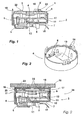
- FIG. 2 again shows the cover 6 in a perspective view, in particular, the insertion opening 13 and the Sp Schwarzfederbeine 8 can be seen.
- the lid 6 has a plurality of locking opening extensions 16, which serve the purpose of connecting the mounting module 2 with another mounting module.
- the mounting module 17 is an adapter or coupling body, which is secured by an adhesive layer 18 on the inside of the windshield 19 of a motor vehicle not otherwise shown. The connection of the mounting module 17 on the inside of the windshield 18 by gluing.
- the mounting module 17 has latching lugs 20 which engage with each other in the openings 21 of the latching openings 16 for connecting the two mounting modules 2, 17.
- the adjusting pins 22 serve the purpose that when connecting of the mounting module 2 with the mounting module 17 - and thus in general form when connecting a first mounting module (here: mounting module 17) with a second mounting module (here: mounting module 2) - these come to rest on the bottom 23 of the mounting body 17, so that in Due to the relative movement of the two mounting modules 2, 17 to each other the lens holder 9 due to the support elements 10 also the board 4 with its connector part 5 against the force of Sp Schwarzfederbeine 8 to the rear cover part 7 of the lid 6 are moved towards.
- the moving by this assembly movement in the manner described sensor 1 can be detected in Figure 3 on the basis of the distance of the locking lugs 11 of the lens holder 9 of the undercut 12 of the lid 6.
- the access opening of the plug connection part 5 comes into an aligned arrangement with the insertion opening 13 of the cover 6, so that in the position of the sensor 1 opposite the cover 6 shown in FIG Plug connection part 5 can be brought together. Only after merging the two connector parts 14, 5, a first energization of the sensor 1, with which an initialization process or process is triggered and run, take place. In this initialization process, the sensor 1 is adapted to existing measurement conditions, for example to the transmittance of the windshield 19.
- the now functional rain sensor as a sensor device is designated in Figure 3 by the reference numeral 24.
- the initialization process can only take place when the two assembly modules are connected to one another as intended and it is thus ensured that the rain sensor is actually formed and arranged on the inside of the windshield. Thus, faulty initialization triggers are prevented.
- a sensor device by further securing measures to the effect that a manual displacement of the sensor 1 within the lid 6 is avoided.
- This can be realized, for example, in that only the connector part assigned to the sensor is movable in the mounting direction and can be moved above the mounted on the windshield mounting module associated adjusting elements which pass through the board.
- a closure element is arranged within the lid, is blocked by the non-mounted mounting module, a connection to the connection plug connection part.
- This closure element is suitably kinematically coupled to a mounting movement of the two mounting modules, so that this is moved together in connecting the two mounting modules in its open position.
Landscapes
- Engineering & Computer Science (AREA)
- Automation & Control Theory (AREA)
- Mechanical Engineering (AREA)
- Physics & Mathematics (AREA)
- General Physics & Mathematics (AREA)
- Details Of Connecting Devices For Male And Female Coupling (AREA)
- Investigating Or Analysing Materials By Optical Means (AREA)
- Measuring Fluid Pressure (AREA)
- Measuring Pulse, Heart Rate, Blood Pressure Or Blood Flow (AREA)
- Transmission And Conversion Of Sensor Element Output (AREA)
Description
- Die Erfindung betrifft eine Sensoreinrichtung, umfassend ein erstes Montagemodul und ein zum Betreiben der Sensoreinrichtung mit dem ersten Montagemodul verbundenes zweites Montagemodul, wobei die Sensoreinrichtung bei ihrer ersten Inbetriebnahme einen Initialisierungsprozess zu durchlaufen hat.
- Sensoreinrichtungen finden im Automotive-Bereich vielfältigen Einsatz. Eingesetzt werden solche Sensoreinrichtungen, wenn diese optoelektronisch arbeitend ausgelegt sind, beispielsweise als Regensensor, Umgebungslichtsensor, Sonnenstandsensor oder dergleichen. Diese Sensoreinrichtungen umfassen zumindest zwei Montagemodule, wobei ein Montagemodul in aller Regel bereits am Kraftfahrzeug angeordnet ist, bevor das zweite Montagemodul daran befestigt wird. Bei dem ersten Montagemodul handelt es sich bei der Ausbildung einer solchen Sensoreinrichtung als Regensensor um einen Adapter oder Koppelkörper, mit dem der eigentliche Regensensor an der Innenseite der Windschutzscheibe befestigt wird. Der Adapter selbst ist an der Windschutzscheibe in aller Regel durch eine Klebung gehalten. Zum Ausbilden der Sensoreinrichtung - hier: Regensensor - ist an dem an der kraftfahrzeugseitig eingebauten Windschutzscheibe befestigten Adapter das zweite Montagemodul mit dem eigentlichen Sensor anzubringen. Ferner muss das zweite Montagemodul an einen Anschlusskabelsatz angeschlossen werden, über den die Sensoreinrichtung mit einer Spannungsquelle und gleichfalls mit einer Auswerte- und/oder Steuereinheit verbindbar ist. Zu diesem Zweck verfügt das zweite Montagemodul über ein Steckverbindungsteil, das mit einem fliegenden Gegensteckverbindungsteil, angeordnet an dem freien Ende des Anschlusskabelsatzes, zusammenzuführen ist.
- Eine solche, beispielsweise als Regensensor ausgelegte Sensoreinrichtung durchläuft bei ihrer ersten Bestromung und somit ggf. bereits bei dem Zusammenführen der beiden Steckverbindungsteile einen Initialisierungsprozess. Mit einem solchen Initialisierungsprozess erfolgt eine Einstellung des Arbeitspunktes der Sensoreinrichtung, etwa hinsichtlich des Sendestroms der zum Betreiben des Regensensors eingesetzten LEDs, der Verstärkereinstellung oder dergleichen. Berücksichtigt werden bei einem solchen Initialisierungsprozess Toleranzen hinsichtlich der Ausbildung und Anordnung der einzelnen Elemente der Sensoreinrichtung und - wie im Falle eines Regensensors - auch der Transmissionsgrad der Windschutzscheibe. Damit der Initialisierungsvorgang bestimmungsgemäß erst dann abläuft, wenn das zweite Montagemodul an dem ersten Montagemodul befestigt ist und somit die Sensoreinrichtung ihre bestimmungsgemäße Anordnung aufweist, darf eine Bestromung der Sensoreinrichtung und somit ein Anschluss derselben an die Spannungsquelle erst dann erfolgen, wenn die beiden Montagemodule miteinander verbunden sind. Daher ist sicherzustellen, dass tatsächlich ein Verbinden der beiden Steckverbindungsteile erst erfolgt, wenn die Sensoreinrichtung durch Verbinden der beiden Montagemodule bestimmungsgemäß realisiert worden ist. Es kommt jedoch immer wieder vor, dass bei der Ausrüstung eines Kraftfahrzeuges mit derartigen Sensoreinrichtungen, beispielsweise mit einem Regensensor zunächst das zweite Montagemodul mit dem Anschlussstecker verbunden wird, bevor tatsächlich das zweite Montagemodul an dem ersten Montagemodul angebracht wird. Folglich läuft bei einer solchen Handhabung der Initialisierungsprozess unter falschen Umgebungsbedingungen ab. Daher ist eine solche Sensoreinrichtung in einem solchen Falle falsch initialisiert mit der Folge, dass ein bestimmungsgemäßer Betrieb nicht gegeben ist. Dies kann zwar korrigiert werden, indem die Sensoreinrichtung neu initialisiert wird, jedoch kann zumeist erst bei einem späteren Betrieb des Kraftfahrzeuges festgestellt werden, ob eine Montage einer solchen Sensoreinrichtung in der richtigen Reihenfolge vorgenommen und somit der Initialisierungsprozess bestimmungsgemäß durchlaufen worden ist.
- EP 1 191 352 A2 offenbart eine Schnittstelle für eine Lichtschrankenanordnung, d.h. also für eine optoelektronische Sensoreinrichtung. Diese Schnittstelle besteht aus einer ersten Schnittstellenkomponente, die integraler Bestandteil der Lichtschrankenanordnung sein kann, und einem damit koppelbaren externen Schnittstellenelement. Als externes Schnittstellenelement kann hierbei auch eine besondere Ausführungsform für einen sog. "Teach-in" Betrieb vorgesehen sein, bei dem eine Konfiguration der Lichtschrankeneinrichtung stattfindet. Für den Normalbetrieb der Einrichtung muss diese jedoch wieder durch ein externes Schnittstellenelement gemäß einer anderen Ausführungsform ersetzt werden.
- Ausgehend von diesem diskutierten Stand der Technik liegt der Erfindung daher die Aufgabe zugrunde, eine eingangs genannte gattungsgemäße Sensoreinrichtung dergestalt weiterzubilden, dass bei dieser gewährleistet ist, dass der Initialisierungsprozess erst dann durchlaufen wird, wenn die beiden Montagemodule bestimmungsgemäß miteinander verbunden sind.
- Diese Aufgabe wird erfindungsgemäß dadurch gelöst, dass die Sensoreinrichtung ferner eine Initialisierungssicherung umfasst, durch die bei nicht verbundenen Montagemodulen das Durchlaufen des Initialisierungsprozesses verhindert ist und die durch eine Relativbewegung der beiden Montagemodule bei ihrer Montage miteinander zur Ausbildung der Sensoreinrichtung in ihre Freigabestellung geschaltet wird.
- Diese Sensoreinrichtung verfügt über eine Initialisierungssicherung, durch die das Durchlaufen des Initialisierungsprozesses bzw. -vorganges solange verhindert ist, bis beide Montagemodule bestimmungsgemäß miteinander verbunden sind. Die Initialisierungssicherung wird durch die Relativbewegung der beiden Montagemodule gegeneinander bei ihrer Montage miteinander zur Ausbildung der Sensoreinrichtung in ihre Freigabestellung geschaltet. Somit ist bei einer solchen Sensoreinrichtung sichergestellt, dass der Initialisierungsprozess erst dann abläuft, wenn die Sensoreinrichtung durch Verbinden der beiden Montagemodule miteinander bestimmungsgemäß ausgebildet ist.
- Die Initialisierungssicherung kann mechanisch und/oder elektrisch /elektronisch arbeitend ausgelegt sein. Bei einer mechanisch arbeitenden Initialisierungssicherung kann vorgesehen sein, dass das Einführen des an dem freien Ende eines Anschlusskabelsatzes befindlichen Steckverbindungsteils zum Anschließen des eigentlichen Sensors an eine Spannungsquelle bzw. auch zum Anschließen desselben an eine Auswerteeinheit erst möglich ist, wenn beide Montagemodule miteinander verbunden sind. Dies kann beispielsweise dadurch realisiert sein, dass die Einstecköffnung zum Einstecken des an dem Anschlusskabelsatz befindlichen Steckverbindungsteils verschlossen ist, wenn das zweite Montagemodul nicht mit dem ersten Montagemodul bestimmungsgemäß verbunden ist. Eine solche Blockierung der Einstecköffnung kann beispielsweise durch einen Verschluss realisiert sein, der beim Verbinden des zweiten Montagemoduls mit dem ersten Montagemodul in seine Offen-Stellung (Freigabestellung) bewegt und somit geschaltet wird. Dabei ist es möglich, die Bewegungsbahn eines solchen Verschlusselementes fluchtend mit der Montagebewegung der beiden Montagemodule gegeneinander vorzusehen oder auch dergestalt zu konzipieren, dass das Verschlusselement durch eine rotatorische Bewegung der beiden Montagemodule gegeneinander in seine Offen-Stellung gebracht wird. In einer weiteren Ausgestaltung einer solchen mechanisch wirkenden Initialisierungssicherung ist vorgesehen, dass eine Einsteckbewegung des Anschlusssteckverbindungsteils, wenn das zweite Montagemodul noch nicht mit dem ersten Montagemodul verbunden ist, dadurch blockiert ist, dass sich das dem zweiten Montagemodul zugeordnete Steckverbindungsteil in einer nicht fluchtenden Lage mit einer in einem dem zweiten Montagemodul zugeordneten Gehäuse befindlichen Einstecköffnung befindet. Folglich ist zwar grundsätzlich ein Einführen des Anschlusssteckverbindungsteils in die Einstecköffnung des Gehäuses möglich, ein bestimmungsgemäßes Zusammenstecken der beiden Steckverbindungsteile ist jedoch verhindert. Das dem zweiten Montagemodul zugeordnete Steckverbindungsteil ist beispielsweise auf einer Platine angeordnet, die ihrerseits in Montagerichtung der beiden Montagemodule bewegbar in dem Gehäuse des zweiten Montagemoduls aufgenommen ist. Durch Verbinden der beiden Montagemodule wird bei diesem Ausführungsbeispiel die Platine zusammen mit dem Steckverbindungsteil in eine Position bewegt, in der das Steckverbindungsteil mit der Einstecköffnung des Gehäuses fluchtet, so dass dann das Anschlusssteckverbindungsteil bestimmungsgemäß mit dem Steckverbindungsteil der Sensoreinrichtung verbunden werden kann.
- Bei einer Auslegung der Initialisierungseinrichtung als elektrische /elektronische Schalteinrichtung kann beispielsweise vorgesehen sein, diese als elektrischen Schalter, insbesondere berührungslos arbeitend, zu konzipieren. Bei einer solchen Ausgestaltung kann der Initialisierungsprozess erst dann durchlaufen werden, wenn sich die elektrische Schalteinrichtung in einer vorbestimmten Schaltposition befindet, durch die gewährleistet ist, dass die beiden Montagemodule bestimmungsgemäß miteinander verbunden sind. Als berührungslose Schalteinrichtung kann beispielsweise ein Hall-Sensor eingesetzt werden, der dem zweiten Montagemodul zugeordnet ist. Bei einer solchen Ausgestaltung kann dem ersten Montagemodul ein Magnet zugeordnet sein, der durch Verbinden der beiden Montagemodule miteinander in eine bestimmte, von dem Hall-Sensor detektierbare Position gebracht wird. Das in dieser Stellung ausgangsseitig am Hall-Sensor anliegende Signal stellt sodann ein Triggersignal zum Auslösen des Initialisierungsprozesses dar. Durch Zusammenführen der beiden Montageelemente ist somit auch bei dieser Ausgestaltung die Initialisierungssicherung dann in ihre Freigabe-Stellung geschaltet. Anstelle der vorgeschriebenen elektrischen/elektronischen Ausgestaltung der Initialisierungssicherung können auch andere zum Einsatz kommen, beispielsweise optisch arbeitende oder auch mechanische Schalter.
- Nachfolgend ist die Erfindung anhand eines Ausführungsbeispiels unter Bezugnahme auf die beigefügten Figuren beschrieben. Es zeigen:
- Fig. 1
- einen schematisierten Querschnitt durch ein Montagemodul einer Sensoreinrichtung,
- Fig. 2
- eine perspektivische Darstellung des Gehäuses des Montagemoduls der Figur 1 und
- Fig. 3
- einen schematisierten Querschnitt durch das mit einem weiteren Montagemodul verbundene Montagemodul der Figur 1.
- Ein Sensor 1 ist Teil eines Montagemoduls 2 zum Ausbilden einer Sensoreinrichtung, die bei dem dargestellten Ausführungsbeispiel ein Regensensor für ein Kraftfahrzeug ist. Bei dem Sensor 1 handelt es sich um einen optischen Sensor mit einzelnen Linsen 3, 3' die oberhalb einer Platine 4 angeordnet sind. Auf der Platine 4 sind photoelektrische Sende- und Empfangselemente, beispielsweise LEDs und Photodioden und weitere, zum Betreiben des Sensors 1 benötigte elektrische/elektronische Baugruppen angeordnet. Auf der von den Linsen 3, 3' wegweisenden Seite der Platine 4 ist an dieser ferner ein Steckverbindungsteil 5 befestigt. Eingefasst sind die beschriebenen Elemente des Sensors 1 in einem gehäuseartigen Deckel 6. Von dem rückwärtigen Deckelteil 7 nach innen abragend sind an diesem Spreizfederbeine 8 angeformt, deren federnde Eigenschaften aus der Materialelastizität des zum Herstellen des Deckels 6 eingesetzten Kunststoffes resultieren. Die in Figur 1 gezeigte Unterseite der Platine 4 stützt sich an den Spreizfederbeinen 8 ab. Gehalten wird die Platine 4 in dem Deckel 6 durch einen die Linsen 3, 3' tragenden Linsenhalter 9, der sich auf der Oberseite der Platine 4 durch Stützelemente 10 abstützt. Der Linsenhalter 9 verfügt über Rastnasen 11, die zum Halten des Linsenhalters 9 und somit auch zum Halten der Platine 4 in dem Deckel jeweils einen Hinterschnitt 12 des Deckels 6 hintergreifen. Dabei ist vorgesehen, dass der Hinterschnitt 12 entgegen der durch die Spreizfederbeine 8 bereitgestellten Federkraft wirkt. Somit befindet sich der Sensor 1 in dem Deckel 6 durch die aus den Spreizfederbeinen 8 resultierenden Federkraft in einer stabilen Lage.
- Der Linsenhalter 9 ist zusammen mit der Platine 4 zum rückwärtigen Deckelteil 7 hin gegen die Kraft der Spreizfederbeine 8 bewegbar in dem Deckel 6 angeordnet. In der in Figur 1 gezeigten Stellung befindet sich der eigentliche Sensor 1 in einer ersten Stellung innerhalb des Deckels 6.
- Der Deckel 6 verfügt über eine Einstecköffnung 13, durch die ein Anschlusssteckverbindungsteil 14, das an dem freien Ende eines Anschlusskabelsatzes 15 angeordnet ist, zum Kontaktieren des Sensors 1 eingeschoben werden kann. Eine tatsächliche Kontaktierung zwischen dem Anschlusssteckverbindungsteil 14 und dem von der Platine 4 getragenen Steckverbindungsteil 5 ist in der in Figur 1 gezeigten Stellung jedoch nicht möglich, da das Steckverbindungsteil 5 bezüglich seiner Zugangsöffnung nicht mit der Einstecköffnung 13 des Deckels 6 fluchtet. Das Anschlusssteckverbindungsteil 14 stößt mit seiner vorderen Stirnseite an die Stirnseite des Steckverbindungsteils 5. Eine Kontaktierung und somit auch ein Anschließen des Sensors 1 an eine Spannungsquelle ist somit in dieser in Figur 1 gezeigten Anordnung zwischen Sensor 1 und Deckel 6 nicht möglich.
- Figur 2 zeigt nochmals den Deckel 6 in einer perspektivischen Ansicht, wobei insbesondere die Einstecköffnung 13 und die Spreizfederbeine 8 erkennbar sind. Der Deckel 6 verfügt über mehrere Rastöffnungsfortsätze 16, die dem Zweck dienen, das Montagemodul 2 mit einem weiteren Montagemodul zu verbinden.
- Zur Ausbildung der eigentlichen Sensoreinrichtung - dem Regensensor in dem dargestellten Ausführungsbeispiel - wird das Montagemodul 2, wie in Figur 3 gezeigt, mit einem weiteren Montagemodul 17 verbunden. Das Montagemodul 17 ist ein Adapter bzw. Koppelkörper, der durch eine Kleberschicht 18 an der Innenseite der Windschutzscheibe 19 eines im übrigen nicht näher dargestellten Kraftfahrzeuges befestigt ist. Die Verbindung des Montagemoduls 17 an der Innenseite der Windschutzscheibe 18 erfolgt durch Klebung.
- Das Montagemodul 17 verfügt über Rastnasen 20, die zum Verbinden der beiden Montagemodule 2, 17 miteinander in die Öffnungen 21 der Rastöffnungsfortsätze 16 eingreifen. Auf der Oberseite des die Linsen 3, 3' tragenden Linsenhalters 9 sind mehrere Stellzapfen 22, deren oberer Abschluss jeweils in einer gemeinsamen Ebene angeordnet ist, abragend angeordnet. Die Stellzapfen 22 dienen dem Zweck, dass beim Verbinden des Montagemoduls 2 mit dem Montagemodul 17 - und somit in allgemeiner Form beim Verbinden eines ersten Montagemoduls (hier: Montagemodul 17) mit einem zweiten Montagemodul (hier: Montagemodul 2) - diese zur Anlage an der Unterseite 23 des Montagekörpers 17 gelangen, so dass im Zuge der Relativbewegung der beiden Montagemodule 2, 17 zueinander der Linsenhalter 9 infolge der Stützelemente 10 ebenfalls die Platine 4 mit ihrem Steckverbindungsteil 5 gegen die Kraft der Spreizfederbeine 8 zum rückwärtigen Deckelteil 7 des Deckels 6 hin bewegt werden. Der durch diese Montagebewegung in der beschriebenen Weise bewegte Sensor 1 kann in Figur 3 anhand des Abstandes der Rastnasen 11 des Linsenhalters 9 von dem Hinterschnitt 12 des Deckels 6 erkannt werden. Durch diese zum rückwärtigen Deckelteil 7 hin gerichtete Bewegung gelangt die Zugangsöffnung des Steckverbindungsteils 5 in eine fluchtende Anordnung mit der Einstecköffnung 13 des Deckels 6, so dass in der in Figur 3 gezeigten Stellung des Sensors 1 gegenüber dem Deckel 6 das Anschlusssteckverbindungsteil 14 ohne weiteres mit dem Steckverbindungsteil 5 zusammengeführt werden kann. Erst nach Zusammenführen der beiden Steckverbindungsteile 14, 5 kann eine erste Bestromung des Sensors 1, mit der ein Initialisierungsprozess bzw. -vorgang ausgelöst und durchlaufen wird, erfolgen. Bei diesem Initialisierungsprozess erfolgt eine Adaption des Sensors 1 an vorhandene Messbedingungen, beispielsweise an den Transmissionsgrad der Windschutzscheibe 19.
- Der nunmehr funktionstüchtige Regensensor als Sensoreinrichtung ist in Figur 3 mit dem Bezugszeichen 24 bezeichnet.
- Aus der Beschreibung der Sensoreinrichtung wird deutlich, dass der Initialisierungsprozess erst dann ablaufen kann, wenn die beiden Montagemodule bestimmungsgemäß miteinander verbunden sind und somit sichergestellt ist, dass der Regensensor tatsächlich ausgebildet und an der Innenseite der Windschutzscheibe angeordnet ist. Somit sind fehlerhafte Initialisierungsauslösungen verhindert.
- Anstelle der in den Figuren gezeigten Ausgestaltung besteht ebenfalls die Möglichkeit, eine Sensoreinrichtung durch weitere Sicherungsmaßnahmen dahingehend zu sichern, dass auch ein manuelles Verschieben des Sensors 1 innerhalb des Deckels 6 vermieden ist. Dies lässt sich beispielsweise dadurch realisieren, dass lediglich das dem Sensor zugeordnete Steckverbindungsteil in Montagerichtung beweglich ist und über dem an der Windschutzscheibe befestigten Montagemodul zugeordnete Stellelemente bewegt werden können, die die Platine durchgreifen. Gleichfalls sind Ausgestaltungen realisierbar, bei denen ein Verschlusselement innerhalb des Deckels angeordnet ist, durch das bei nicht montiertem Montagemodul ein Anschluss mit dem Anschlusssteckverbindungsteil blockiert ist. Dieses Verschlusselement ist in geeigneter Weise kinematisch an einer Montagebewegung der beiden Montagemodule gekoppelt, so dass dieses beim Verbinden der beiden Montagemodule miteinander in seine Offen-Stellung bewegt wird. Als Sensoreinrichtungen können sämtliche optoelektronischen Sensoreinrichtungen dienen, die einen vorbeschriebenen Initialisierungsprozess durchlaufen müssen.
-
- 1
- Sensor
- 2
- Montagemodul
- 3, 3'
- Linse
- 4
- Platine
- 5
- Steckverbindungsteil
- 6
- Deckel
- 7
- Deckelteil
- 8
- Spreizfederbeine
- 9
- Linsenhalter
- 10
- Stützelement
- 11
- Rastnase
- 12
- Hinterschnitt
- 13
- Einstecköffnung
- 14
- Anschlusssteckverbindungsteil
- 15
- Anschlusskabelsatz
- 16
- Rastöffnungsfortsatz
- 17
- Montagemodul
- 18
- Kleberschicht
- 19
- Windschutzscheibe
- 20
- Rastnase
- 21
- Rastöffnung
- 22
- Stellzapfen
- 23
- Unterseite
- 24
- Regensensor
Claims (10)
- Optoelektronische Sensoreinrichtung, umfassend ein erstes Montagemodul (17) und ein zum Betreiben der Sensoreinrichtung mit dem ersten Montagemodul (17) zu verbindendes zweites Montagemodul (2), wobei die Sensoreinrichtung (24) bei ihrer ersten Inbetriebnahme einen Initialisierungsprozess zu durchlaufen hat, dadurch gekennzeichnet, dass die Sensoreinrichtung (24) ferner eine Initialisierungssicherung umfasst, durch die bei nicht verbundenen Montagemodulen (2, 17) das Durchlaufen des Initialisierungsprozesses verhindert ist, wobei die Initialisierungssicherung durch eine Relativbewegung der beiden Montagemodule (2, 17) bei ihrer Montage miteinander zur Ausbildung der Sensoreinrichtung (24) in ihre Freigabestellung geschaltet wird.
- Sensoreinrichtung nach Anspruch 1, dadurch gekennzeichnet, dass die Sensoreinrichtung (24) eine dem zweiten Montagemodul (2) zugeordnete elektrische Anschlußeinrichtung (5) aufweist, über die die Sensoreinrichtung (24) an eine Spannungsquelle anschließbar ist, und dass die Initialisierungssicherung mechanisch wirkend ausgelegt ist, wobei durch diese in ihrer Geschlossen-Stellung ein Anschluß der Sensoreinrichtung (24) an die Spannungsquelle blockiert ist.
- Sensoreinrichtung nach Anspruch 1 oder 2, dadurch gekennzeichnet, dass die Initialisierungssicherung durch ein dem zweiten Montagemodul (2) zugeordnetes Steckverbindungsteil (5) und eine einem dem Steckverbindungsteil (5) zumindest im Bereich seines Zugangs einschließenden Gehäuse (6) zugeordnete Einstecköffnung (13) zum Einführen eines Gegensteckverbindungsteils (14) zum elektrischen Anschließen der Sensoreinrichtung (24) gebildet ist, wobei das Steckverbindungsteil (5) gegenüber der Einstecköffnung (13) des Gehäuses (6) bewegbar in dem Gehäuse (6) gehalten ist und durch ein Federelement (8) in seiner ein Einsetzen des Gegensteckverbindungsteils (14) blockierenden Stellung gehalten ist, wenn das erste Montagemodul (17) nicht mit dem zweiten Montagemodul (2) verbunden ist.
- Sensoreinrichtung nach Anspruch 3, dadurch gekennzeichnet, dass das Steckverbindungsteil (5) auf einer Platine (4) des zweiten Montagemoduls (2) angeordnet ist.
- Sensoreinrichtung nach Anspruch 3 oder 4, dadurch gekennzeichnet, dass das erste Montagemodul über Stellelemente verfügt, mit denen bei einem Verbinden der beiden Montagemodule miteinander das Steckverbindungsteil gegenüber der Einstecköffnung des Gehäuses zum Freigeben der Einstecköffnung bewegt wird.
- Sensoreinrichtung nach Anspruch 5, dadurch gekennzeichnet, dass die Stellelemente Stellzapfen sind.
- Sensoreinrichtung nach Anspruch 1, dadurch gekennzeichnet, dass die Initialisierungssicherung durch einen elektrischen Schalter gebildet ist.
- Sensoreinrichtung nach Anspruch 7, dadurch gekennzeichnet, dass der elektrische Schalter berührungslos arbeitend ausgelegt ist.
- Sensoreinrichtung nach einem der Ansprüche 1 bis 8, dadurch gekennzeichnet, dass die Sensoreinrichtung ein Regensensor ist.
- Sensoreinrichtung nach Anspruch 9, dadurch gekennzeichnet, dass die Initialisierungssicherung ein in den Strahlengang der Optik eingebrachter Verschluss ist.
Applications Claiming Priority (3)
| Application Number | Priority Date | Filing Date | Title |
|---|---|---|---|
| DE10309758 | 2003-03-06 | ||
| DE10309758A DE10309758A1 (de) | 2003-03-06 | 2003-03-06 | Sensoreinrichtung |
| PCT/EP2004/002193 WO2004079300A1 (de) | 2003-03-06 | 2004-03-04 | Sensoreinrichtung |
Publications (2)
| Publication Number | Publication Date |
|---|---|
| EP1599704A1 EP1599704A1 (de) | 2005-11-30 |
| EP1599704B1 true EP1599704B1 (de) | 2007-05-09 |
Family
ID=32864196
Family Applications (1)
| Application Number | Title | Priority Date | Filing Date |
|---|---|---|---|
| EP04717045A Expired - Lifetime EP1599704B1 (de) | 2003-03-06 | 2004-03-04 | Sensoreinrichtung |
Country Status (5)
| Country | Link |
|---|---|
| EP (1) | EP1599704B1 (de) |
| AT (1) | ATE362094T1 (de) |
| DE (2) | DE10309758A1 (de) |
| ES (1) | ES2286615T3 (de) |
| WO (1) | WO2004079300A1 (de) |
Families Citing this family (8)
| Publication number | Priority date | Publication date | Assignee | Title |
|---|---|---|---|---|
| DE102005018379A1 (de) * | 2005-04-21 | 2006-10-26 | Leopold Kostal Gmbh & Co. Kg | Optoelektronische Sensoreinrichtung |
| DE202006000853U1 (de) * | 2006-01-19 | 2007-05-24 | Trw Automotive Electronics & Components Gmbh & Co. Kg | Halteklammer für einen Regensensor |
| DE102006040213C5 (de) | 2006-01-19 | 2019-08-01 | Bcs Automotive Interface Solutions Gmbh | Halteklammer für einen Regensensor |
| DE102007029946B4 (de) * | 2007-06-28 | 2010-08-19 | Festo Ag & Co. Kg | Sensoreinrichtung |
| DE102007055114A1 (de) * | 2007-11-19 | 2009-05-20 | Volkswagen Ag | Verfahren zum sicheren Anbringen eines Sensors an einem Kraftfahrzeug und entsprechend ausgestalteter Sensor und Kraftfahrzeug |
| DE102007061103A1 (de) * | 2007-12-19 | 2009-06-25 | Robert Bosch Gmbh | Regensensor mit Bajonettverschluss |
| DE102013114140A1 (de) * | 2013-12-16 | 2015-06-18 | Endress + Hauser Wetzer Gmbh + Co. Kg | Messfühlergehäuse und Messfühleranordnung mit einem Messfühlergehäuse |
| CN115342920B (zh) * | 2021-05-12 | 2025-09-09 | 芜湖美的厨卫电器制造有限公司 | 颜色传感装置和厨房电器 |
Family Cites Families (6)
| Publication number | Priority date | Publication date | Assignee | Title |
|---|---|---|---|---|
| DE3724927A1 (de) * | 1987-07-28 | 1989-02-09 | Bayerische Motoren Werke Ag | Schalteinrichtung mit einem schaltelement und einem betaetigungselement |
| GB9208190D0 (en) * | 1992-04-11 | 1992-05-27 | Elcometer Instr Ltd | Measuring instrument |
| DE29903260U1 (de) * | 1999-02-23 | 2000-04-13 | Siemens AG, 80333 München | Meßumformer |
| DE10046863C1 (de) * | 2000-09-20 | 2002-01-10 | Leuze Lumiflex Gmbh & Co | Schnittstelle für Lichtschrankenanordnungen |
| DE10203484A1 (de) * | 2001-06-08 | 2002-12-12 | Continental Teves Ag & Co Ohg | Drucksensoranordnung für Kraftfahrzeugbremssysteme und Verfahren zur Kalibrierung eines Drucksensors |
| US20030002562A1 (en) * | 2001-06-27 | 2003-01-02 | Yerlikaya Y. Denis | Temperature probe adapter |
-
2003
- 2003-03-06 DE DE10309758A patent/DE10309758A1/de not_active Withdrawn
-
2004
- 2004-03-04 DE DE502004003760T patent/DE502004003760D1/de not_active Expired - Lifetime
- 2004-03-04 ES ES04717045T patent/ES2286615T3/es not_active Expired - Lifetime
- 2004-03-04 EP EP04717045A patent/EP1599704B1/de not_active Expired - Lifetime
- 2004-03-04 WO PCT/EP2004/002193 patent/WO2004079300A1/de not_active Ceased
- 2004-03-04 AT AT04717045T patent/ATE362094T1/de not_active IP Right Cessation
Non-Patent Citations (1)
| Title |
|---|
| None * |
Also Published As
| Publication number | Publication date |
|---|---|
| ES2286615T3 (es) | 2007-12-01 |
| EP1599704A1 (de) | 2005-11-30 |
| DE502004003760D1 (de) | 2007-06-21 |
| DE10309758A1 (de) | 2004-09-16 |
| WO2004079300A1 (de) | 2004-09-16 |
| ATE362094T1 (de) | 2007-06-15 |
Similar Documents
| Publication | Publication Date | Title |
|---|---|---|
| EP2535985B1 (de) | Steckdose eines Kraftfahrzeugs | |
| EP1599704B1 (de) | Sensoreinrichtung | |
| DE102015113875A1 (de) | Steckverbinderteil mit einem Verriegelungselement | |
| DE102006047039A1 (de) | Kontaktverbindung, insbesondere zur lösbaren elektrischen Anbindung eines elektrischen Antriebsmotors eines Kraftfahrzeugs | |
| DE4111049A1 (de) | Steckverbindung fuer eine schichtfoermige elektrode zur ionenkonzentrationsmessung | |
| DE112018008055T5 (de) | Elektrische Vorrichtung | |
| EP0846351B1 (de) | Anordnung mit zwei steckerhälften zur fixierung in einer wandung | |
| EP4324051B1 (de) | Klemmfederkontakteinrichtung mit überdehnschutz und steckverbindereinsatz mit mindestens einer solchen klemmfederkontakteinrichtung | |
| DE102020124092B4 (de) | Steckverbinderanordnung zum Verbinden einer elektrischen Leitung mit einem elektrischen Bauelement | |
| DE102017213941B4 (de) | Steckverbinder mit Kurzschlussklemme | |
| WO2025119422A1 (de) | Steckverbindermodul für einen modularen industriesteckverbinder | |
| EP0647988A1 (de) | Steckverbinder-Kupplung | |
| DE69504742T2 (de) | Stecker | |
| DE69834153T2 (de) | Elektrische Anordnung mit Betätigungsvorrichtung für einen Lastschalter mit Fehlfunktionsanzeigeeinrichtung | |
| DE102019116204B3 (de) | Steckverbindersystem mit voneinander zwangstrennbaren Steckverbinderteilen | |
| BE1030493B1 (de) | Kontakteinsatz für ein steckend mit einem Gegensteckverbinderteil verbindbares Steckverbinderteil | |
| DE102013226194A1 (de) | Elektrisches Steckerelement | |
| EP2860826B1 (de) | Elektrische Steckverbindung mit einem Federelement | |
| DE102023106339A1 (de) | Erdungsmodul für ein Steckverbindermodularsystem sowie Steckverbindermodularsystem und modularer Steckverbinder mit demselben | |
| DE19608899A1 (de) | Anordnung mit zwei Steckerhälften zur Fixierung in einer Wandung | |
| DE102023212427A1 (de) | Schutzschaltermodul | |
| WO2024078889A1 (de) | Glasscheibenvorrichtung sowie kraftfahrzeug | |
| DE102024115466A1 (de) | Steckverbinderanordnung mit steckzustandserfassung | |
| WO2024240297A1 (de) | Halterahmen für ein steckverbindergehäuse eines industriesteckverbinders | |
| WO2025237469A1 (de) | Erdungsmodul für einen modularen industriesteckverbinder |
Legal Events
| Date | Code | Title | Description |
|---|---|---|---|
| PUAI | Public reference made under article 153(3) epc to a published international application that has entered the european phase |
Free format text: ORIGINAL CODE: 0009012 |
|
| 17P | Request for examination filed |
Effective date: 20050813 |
|
| AK | Designated contracting states |
Kind code of ref document: A1 Designated state(s): AT BE BG CH CY CZ DE DK EE ES FI FR GB GR HU IE IT LI LU MC NL PL PT RO SE SI SK TR |
|
| AX | Request for extension of the european patent |
Extension state: AL LT LV MK |
|
| DAX | Request for extension of the european patent (deleted) | ||
| 17Q | First examination report despatched |
Effective date: 20060727 |
|
| GRAP | Despatch of communication of intention to grant a patent |
Free format text: ORIGINAL CODE: EPIDOSNIGR1 |
|
| GRAS | Grant fee paid |
Free format text: ORIGINAL CODE: EPIDOSNIGR3 |
|
| GRAA | (expected) grant |
Free format text: ORIGINAL CODE: 0009210 |
|
| AK | Designated contracting states |
Kind code of ref document: B1 Designated state(s): AT BE BG CH CY CZ DE DK EE ES FI FR GB GR HU IE IT LI LU MC NL PL PT RO SE SI SK TR |
|
| PG25 | Lapsed in a contracting state [announced via postgrant information from national office to epo] |
Ref country code: FI Free format text: LAPSE BECAUSE OF FAILURE TO SUBMIT A TRANSLATION OF THE DESCRIPTION OR TO PAY THE FEE WITHIN THE PRESCRIBED TIME-LIMIT Effective date: 20070509 |
|
| REG | Reference to a national code |
Ref country code: GB Ref legal event code: FG4D Free format text: NOT ENGLISH |
|
| REG | Reference to a national code |
Ref country code: CH Ref legal event code: EP |
|
| REG | Reference to a national code |
Ref country code: IE Ref legal event code: FG4D Free format text: LANGUAGE OF EP DOCUMENT: GERMAN |
|
| REF | Corresponds to: |
Ref document number: 502004003760 Country of ref document: DE Date of ref document: 20070621 Kind code of ref document: P |
|
| PG25 | Lapsed in a contracting state [announced via postgrant information from national office to epo] |
Ref country code: SE Free format text: LAPSE BECAUSE OF FAILURE TO SUBMIT A TRANSLATION OF THE DESCRIPTION OR TO PAY THE FEE WITHIN THE PRESCRIBED TIME-LIMIT Effective date: 20070809 |
|
| GBT | Gb: translation of ep patent filed (gb section 77(6)(a)/1977) |
Effective date: 20070815 |
|
| NLV1 | Nl: lapsed or annulled due to failure to fulfill the requirements of art. 29p and 29m of the patents act | ||
| PG25 | Lapsed in a contracting state [announced via postgrant information from national office to epo] |
Ref country code: PL Free format text: LAPSE BECAUSE OF FAILURE TO SUBMIT A TRANSLATION OF THE DESCRIPTION OR TO PAY THE FEE WITHIN THE PRESCRIBED TIME-LIMIT Effective date: 20070509 |
|
| REG | Reference to a national code |
Ref country code: ES Ref legal event code: FG2A Ref document number: 2286615 Country of ref document: ES Kind code of ref document: T3 |
|
| REG | Reference to a national code |
Ref country code: IE Ref legal event code: FD4D |
|
| EN | Fr: translation not filed | ||
| PG25 | Lapsed in a contracting state [announced via postgrant information from national office to epo] |
Ref country code: BG Free format text: LAPSE BECAUSE OF FAILURE TO SUBMIT A TRANSLATION OF THE DESCRIPTION OR TO PAY THE FEE WITHIN THE PRESCRIBED TIME-LIMIT Effective date: 20070809 Ref country code: CZ Free format text: LAPSE BECAUSE OF FAILURE TO SUBMIT A TRANSLATION OF THE DESCRIPTION OR TO PAY THE FEE WITHIN THE PRESCRIBED TIME-LIMIT Effective date: 20070509 Ref country code: IE Free format text: LAPSE BECAUSE OF FAILURE TO SUBMIT A TRANSLATION OF THE DESCRIPTION OR TO PAY THE FEE WITHIN THE PRESCRIBED TIME-LIMIT Effective date: 20070509 Ref country code: PT Free format text: LAPSE BECAUSE OF FAILURE TO SUBMIT A TRANSLATION OF THE DESCRIPTION OR TO PAY THE FEE WITHIN THE PRESCRIBED TIME-LIMIT Effective date: 20071009 Ref country code: DK Free format text: LAPSE BECAUSE OF FAILURE TO SUBMIT A TRANSLATION OF THE DESCRIPTION OR TO PAY THE FEE WITHIN THE PRESCRIBED TIME-LIMIT Effective date: 20070509 Ref country code: SI Free format text: LAPSE BECAUSE OF FAILURE TO SUBMIT A TRANSLATION OF THE DESCRIPTION OR TO PAY THE FEE WITHIN THE PRESCRIBED TIME-LIMIT Effective date: 20070509 Ref country code: NL Free format text: LAPSE BECAUSE OF FAILURE TO SUBMIT A TRANSLATION OF THE DESCRIPTION OR TO PAY THE FEE WITHIN THE PRESCRIBED TIME-LIMIT Effective date: 20070509 |
|
| PG25 | Lapsed in a contracting state [announced via postgrant information from national office to epo] |
Ref country code: SK Free format text: LAPSE BECAUSE OF FAILURE TO SUBMIT A TRANSLATION OF THE DESCRIPTION OR TO PAY THE FEE WITHIN THE PRESCRIBED TIME-LIMIT Effective date: 20070509 |
|
| PLBE | No opposition filed within time limit |
Free format text: ORIGINAL CODE: 0009261 |
|
| STAA | Information on the status of an ep patent application or granted ep patent |
Free format text: STATUS: NO OPPOSITION FILED WITHIN TIME LIMIT |
|
| 26N | No opposition filed |
Effective date: 20080212 |
|
| PG25 | Lapsed in a contracting state [announced via postgrant information from national office to epo] |
Ref country code: GR Free format text: LAPSE BECAUSE OF FAILURE TO SUBMIT A TRANSLATION OF THE DESCRIPTION OR TO PAY THE FEE WITHIN THE PRESCRIBED TIME-LIMIT Effective date: 20070810 |
|
| PG25 | Lapsed in a contracting state [announced via postgrant information from national office to epo] |
Ref country code: RO Free format text: LAPSE BECAUSE OF FAILURE TO SUBMIT A TRANSLATION OF THE DESCRIPTION OR TO PAY THE FEE WITHIN THE PRESCRIBED TIME-LIMIT Effective date: 20070509 |
|
| PG25 | Lapsed in a contracting state [announced via postgrant information from national office to epo] |
Ref country code: FR Free format text: LAPSE BECAUSE OF FAILURE TO SUBMIT A TRANSLATION OF THE DESCRIPTION OR TO PAY THE FEE WITHIN THE PRESCRIBED TIME-LIMIT Effective date: 20080104 |
|
| BERE | Be: lapsed |
Owner name: LEOPOLD KOSTAL G.M.B.H. & CO. KG Effective date: 20080331 |
|
| PG25 | Lapsed in a contracting state [announced via postgrant information from national office to epo] |
Ref country code: MC Free format text: LAPSE BECAUSE OF NON-PAYMENT OF DUE FEES Effective date: 20080331 |
|
| REG | Reference to a national code |
Ref country code: CH Ref legal event code: PL |
|
| PG25 | Lapsed in a contracting state [announced via postgrant information from national office to epo] |
Ref country code: LI Free format text: LAPSE BECAUSE OF NON-PAYMENT OF DUE FEES Effective date: 20080331 Ref country code: CH Free format text: LAPSE BECAUSE OF NON-PAYMENT OF DUE FEES Effective date: 20080331 Ref country code: EE Free format text: LAPSE BECAUSE OF FAILURE TO SUBMIT A TRANSLATION OF THE DESCRIPTION OR TO PAY THE FEE WITHIN THE PRESCRIBED TIME-LIMIT Effective date: 20070509 |
|
| PG25 | Lapsed in a contracting state [announced via postgrant information from national office to epo] |
Ref country code: BE Free format text: LAPSE BECAUSE OF NON-PAYMENT OF DUE FEES Effective date: 20080331 |
|
| PG25 | Lapsed in a contracting state [announced via postgrant information from national office to epo] |
Ref country code: CY Free format text: LAPSE BECAUSE OF FAILURE TO SUBMIT A TRANSLATION OF THE DESCRIPTION OR TO PAY THE FEE WITHIN THE PRESCRIBED TIME-LIMIT Effective date: 20070509 |
|
| PG25 | Lapsed in a contracting state [announced via postgrant information from national office to epo] |
Ref country code: AT Free format text: LAPSE BECAUSE OF NON-PAYMENT OF DUE FEES Effective date: 20080304 |
|
| PG25 | Lapsed in a contracting state [announced via postgrant information from national office to epo] |
Ref country code: LU Free format text: LAPSE BECAUSE OF NON-PAYMENT OF DUE FEES Effective date: 20080304 Ref country code: HU Free format text: LAPSE BECAUSE OF FAILURE TO SUBMIT A TRANSLATION OF THE DESCRIPTION OR TO PAY THE FEE WITHIN THE PRESCRIBED TIME-LIMIT Effective date: 20071110 |
|
| PG25 | Lapsed in a contracting state [announced via postgrant information from national office to epo] |
Ref country code: TR Free format text: LAPSE BECAUSE OF FAILURE TO SUBMIT A TRANSLATION OF THE DESCRIPTION OR TO PAY THE FEE WITHIN THE PRESCRIBED TIME-LIMIT Effective date: 20070509 |
|
| REG | Reference to a national code |
Ref country code: FR Ref legal event code: EERR Free format text: CORRECTION DE BOPI 08/01 - 3.2. |
|
| REG | Reference to a national code |
Ref country code: FR Ref legal event code: ST Effective date: 20111202 |
|
| REG | Reference to a national code |
Ref country code: FR Ref legal event code: RN Effective date: 20120203 |
|
| REG | Reference to a national code |
Ref country code: FR Ref legal event code: D3 Effective date: 20120907 |
|
| PGRI | Patent reinstated in contracting state [announced from national office to epo] |
Ref country code: FR Effective date: 20120907 |
|
| REG | Reference to a national code |
Ref country code: FR Ref legal event code: PLFP Year of fee payment: 13 |
|
| PGFP | Annual fee paid to national office [announced via postgrant information from national office to epo] |
Ref country code: GB Payment date: 20160323 Year of fee payment: 13 |
|
| PGFP | Annual fee paid to national office [announced via postgrant information from national office to epo] |
Ref country code: ES Payment date: 20160331 Year of fee payment: 13 |
|
| PGFP | Annual fee paid to national office [announced via postgrant information from national office to epo] |
Ref country code: FR Payment date: 20160322 Year of fee payment: 13 Ref country code: IT Payment date: 20160318 Year of fee payment: 13 |
|
| REG | Reference to a national code |
Ref country code: DE Ref legal event code: R084 Ref document number: 502004003760 Country of ref document: DE |
|
| GBPC | Gb: european patent ceased through non-payment of renewal fee |
Effective date: 20170304 |
|
| REG | Reference to a national code |
Ref country code: FR Ref legal event code: ST Effective date: 20171130 |
|
| PG25 | Lapsed in a contracting state [announced via postgrant information from national office to epo] |
Ref country code: FR Free format text: LAPSE BECAUSE OF FAILURE TO SUBMIT A TRANSLATION OF THE DESCRIPTION OR TO PAY THE FEE WITHIN THE PRESCRIBED TIME-LIMIT Effective date: 20170331 |
|
| PG25 | Lapsed in a contracting state [announced via postgrant information from national office to epo] |
Ref country code: GB Free format text: LAPSE BECAUSE OF NON-PAYMENT OF DUE FEES Effective date: 20170304 Ref country code: IT Free format text: LAPSE BECAUSE OF NON-PAYMENT OF DUE FEES Effective date: 20170304 |
|
| PGFP | Annual fee paid to national office [announced via postgrant information from national office to epo] |
Ref country code: DE Payment date: 20180302 Year of fee payment: 15 |
|
| REG | Reference to a national code |
Ref country code: ES Ref legal event code: FD2A Effective date: 20180703 |
|
| PG25 | Lapsed in a contracting state [announced via postgrant information from national office to epo] |
Ref country code: ES Free format text: LAPSE BECAUSE OF NON-PAYMENT OF DUE FEES Effective date: 20170305 |
|
| REG | Reference to a national code |
Ref country code: DE Ref legal event code: R119 Ref document number: 502004003760 Country of ref document: DE |
|
| PG25 | Lapsed in a contracting state [announced via postgrant information from national office to epo] |
Ref country code: DE Free format text: LAPSE BECAUSE OF NON-PAYMENT OF DUE FEES Effective date: 20191001 |