EP1599695B1 - Verdampfungskühler - Google Patents
Verdampfungskühler Download PDFInfo
- Publication number
- EP1599695B1 EP1599695B1 EP04714775.6A EP04714775A EP1599695B1 EP 1599695 B1 EP1599695 B1 EP 1599695B1 EP 04714775 A EP04714775 A EP 04714775A EP 1599695 B1 EP1599695 B1 EP 1599695B1
- Authority
- EP
- European Patent Office
- Prior art keywords
- liquid
- evaporative cooler
- distribution area
- heat exchange
- exchange surface
- Prior art date
- Legal status (The legal status is an assumption and is not a legal conclusion. Google has not performed a legal analysis and makes no representation as to the accuracy of the status listed.)
- Expired - Lifetime
Links
- 239000007788 liquid Substances 0.000 claims description 43
- 238000009826 distribution Methods 0.000 claims description 20
- 230000002262 irrigation Effects 0.000 claims description 18
- 238000003973 irrigation Methods 0.000 claims description 18
- 238000005507 spraying Methods 0.000 claims description 12
- 238000000034 method Methods 0.000 claims description 10
- 239000007921 spray Substances 0.000 claims description 5
- 238000002663 nebulization Methods 0.000 claims description 3
- 238000009736 wetting Methods 0.000 claims description 3
- XLYOFNOQVPJJNP-UHFFFAOYSA-N water Substances O XLYOFNOQVPJJNP-UHFFFAOYSA-N 0.000 description 52
- 238000001704 evaporation Methods 0.000 description 10
- 230000008020 evaporation Effects 0.000 description 10
- 230000015572 biosynthetic process Effects 0.000 description 8
- 208000007764 Legionnaires' Disease Diseases 0.000 description 4
- 239000000443 aerosol Substances 0.000 description 4
- 241000589248 Legionella Species 0.000 description 3
- 206010035718 Pneumonia legionella Diseases 0.000 description 3
- 239000011398 Portland cement Substances 0.000 description 3
- 238000000889 atomisation Methods 0.000 description 3
- 230000005540 biological transmission Effects 0.000 description 3
- 238000001816 cooling Methods 0.000 description 3
- 230000000694 effects Effects 0.000 description 3
- 239000012530 fluid Substances 0.000 description 3
- 239000011490 mineral wool Substances 0.000 description 3
- 229910010293 ceramic material Inorganic materials 0.000 description 2
- 238000000576 coating method Methods 0.000 description 2
- 201000010099 disease Diseases 0.000 description 2
- 208000037265 diseases, disorders, signs and symptoms Diseases 0.000 description 2
- 239000000463 material Substances 0.000 description 2
- 239000004033 plastic Substances 0.000 description 2
- 230000003014 reinforcing effect Effects 0.000 description 2
- 229920006395 saturated elastomer Polymers 0.000 description 2
- 238000000926 separation method Methods 0.000 description 2
- 238000003856 thermoforming Methods 0.000 description 2
- RYGMFSIKBFXOCR-UHFFFAOYSA-N Copper Chemical compound [Cu] RYGMFSIKBFXOCR-UHFFFAOYSA-N 0.000 description 1
- 230000002745 absorbent Effects 0.000 description 1
- 239000002250 absorbent Substances 0.000 description 1
- 239000004411 aluminium Substances 0.000 description 1
- XAGFODPZIPBFFR-UHFFFAOYSA-N aluminium Chemical compound [Al] XAGFODPZIPBFFR-UHFFFAOYSA-N 0.000 description 1
- 229910052782 aluminium Inorganic materials 0.000 description 1
- 239000004568 cement Substances 0.000 description 1
- 238000004140 cleaning Methods 0.000 description 1
- 239000011248 coating agent Substances 0.000 description 1
- 239000010949 copper Substances 0.000 description 1
- 229910052802 copper Inorganic materials 0.000 description 1
- 238000010168 coupling process Methods 0.000 description 1
- 238000005859 coupling reaction Methods 0.000 description 1
- 230000007423 decrease Effects 0.000 description 1
- 238000009792 diffusion process Methods 0.000 description 1
- 239000000284 extract Substances 0.000 description 1
- 239000002657 fibrous material Substances 0.000 description 1
- 238000001746 injection moulding Methods 0.000 description 1
- 238000007689 inspection Methods 0.000 description 1
- 210000004072 lung Anatomy 0.000 description 1
- 230000014759 maintenance of location Effects 0.000 description 1
- 239000011159 matrix material Substances 0.000 description 1
- 238000010137 moulding (plastic) Methods 0.000 description 1
- 230000003071 parasitic effect Effects 0.000 description 1
- 239000002245 particle Substances 0.000 description 1
- 238000003825 pressing Methods 0.000 description 1
- 238000007789 sealing Methods 0.000 description 1
- 239000008400 supply water Substances 0.000 description 1
- 229920001169 thermoplastic Polymers 0.000 description 1
- 239000012815 thermoplastic material Substances 0.000 description 1
- 239000004416 thermosoftening plastic Substances 0.000 description 1
- 238000009827 uniform distribution Methods 0.000 description 1
- 238000011144 upstream manufacturing Methods 0.000 description 1
- 238000007666 vacuum forming Methods 0.000 description 1
Images




Classifications
-
- F—MECHANICAL ENGINEERING; LIGHTING; HEATING; WEAPONS; BLASTING
- F24—HEATING; RANGES; VENTILATING
- F24F—AIR-CONDITIONING; AIR-HUMIDIFICATION; VENTILATION; USE OF AIR CURRENTS FOR SCREENING
- F24F1/00—Room units for air-conditioning, e.g. separate or self-contained units or units receiving primary air from a central station
- F24F1/06—Separate outdoor units, e.g. outdoor unit to be linked to a separate room comprising a compressor and a heat exchanger
- F24F1/42—Separate outdoor units, e.g. outdoor unit to be linked to a separate room comprising a compressor and a heat exchanger characterised by the use of the condensate, e.g. for enhanced cooling
-
- F—MECHANICAL ENGINEERING; LIGHTING; HEATING; WEAPONS; BLASTING
- F24—HEATING; RANGES; VENTILATING
- F24F—AIR-CONDITIONING; AIR-HUMIDIFICATION; VENTILATION; USE OF AIR CURRENTS FOR SCREENING
- F24F1/00—Room units for air-conditioning, e.g. separate or self-contained units or units receiving primary air from a central station
- F24F1/0007—Indoor units, e.g. fan coil units
-
- F—MECHANICAL ENGINEERING; LIGHTING; HEATING; WEAPONS; BLASTING
- F24—HEATING; RANGES; VENTILATING
- F24F—AIR-CONDITIONING; AIR-HUMIDIFICATION; VENTILATION; USE OF AIR CURRENTS FOR SCREENING
- F24F1/00—Room units for air-conditioning, e.g. separate or self-contained units or units receiving primary air from a central station
- F24F1/0007—Indoor units, e.g. fan coil units
- F24F1/0071—Indoor units, e.g. fan coil units with means for purifying supplied air
-
- F—MECHANICAL ENGINEERING; LIGHTING; HEATING; WEAPONS; BLASTING
- F24—HEATING; RANGES; VENTILATING
- F24F—AIR-CONDITIONING; AIR-HUMIDIFICATION; VENTILATION; USE OF AIR CURRENTS FOR SCREENING
- F24F5/00—Air-conditioning systems or apparatus not covered by F24F1/00 or F24F3/00, e.g. using solar heat or combined with household units such as an oven or water heater
- F24F5/0007—Air-conditioning systems or apparatus not covered by F24F1/00 or F24F3/00, e.g. using solar heat or combined with household units such as an oven or water heater cooling apparatus specially adapted for use in air-conditioning
- F24F5/0035—Air-conditioning systems or apparatus not covered by F24F1/00 or F24F3/00, e.g. using solar heat or combined with household units such as an oven or water heater cooling apparatus specially adapted for use in air-conditioning using evaporation
-
- F—MECHANICAL ENGINEERING; LIGHTING; HEATING; WEAPONS; BLASTING
- F28—HEAT EXCHANGE IN GENERAL
- F28C—HEAT-EXCHANGE APPARATUS, NOT PROVIDED FOR IN ANOTHER SUBCLASS, IN WHICH THE HEAT-EXCHANGE MEDIA COME INTO DIRECT CONTACT WITHOUT CHEMICAL INTERACTION
- F28C1/00—Direct-contact trickle coolers, e.g. cooling towers
-
- F—MECHANICAL ENGINEERING; LIGHTING; HEATING; WEAPONS; BLASTING
- F28—HEAT EXCHANGE IN GENERAL
- F28D—HEAT-EXCHANGE APPARATUS, NOT PROVIDED FOR IN ANOTHER SUBCLASS, IN WHICH THE HEAT-EXCHANGE MEDIA DO NOT COME INTO DIRECT CONTACT
- F28D5/00—Heat-exchange apparatus having stationary conduit assemblies for one heat-exchange medium only, the media being in contact with different sides of the conduit wall, using the cooling effect of natural or forced evaporation
- F28D5/02—Heat-exchange apparatus having stationary conduit assemblies for one heat-exchange medium only, the media being in contact with different sides of the conduit wall, using the cooling effect of natural or forced evaporation in which the evaporating medium flows in a continuous film or trickles freely over the conduits
-
- F—MECHANICAL ENGINEERING; LIGHTING; HEATING; WEAPONS; BLASTING
- F24—HEATING; RANGES; VENTILATING
- F24F—AIR-CONDITIONING; AIR-HUMIDIFICATION; VENTILATION; USE OF AIR CURRENTS FOR SCREENING
- F24F6/00—Air-humidification, e.g. cooling by humidification
- F24F6/12—Air-humidification, e.g. cooling by humidification by forming water dispersions in the air
- F24F6/14—Air-humidification, e.g. cooling by humidification by forming water dispersions in the air using nozzles
- F24F2006/146—Air-humidification, e.g. cooling by humidification by forming water dispersions in the air using nozzles using pressurised water for spraying
-
- F—MECHANICAL ENGINEERING; LIGHTING; HEATING; WEAPONS; BLASTING
- F24—HEATING; RANGES; VENTILATING
- F24F—AIR-CONDITIONING; AIR-HUMIDIFICATION; VENTILATION; USE OF AIR CURRENTS FOR SCREENING
- F24F8/00—Treatment, e.g. purification, of air supplied to human living or working spaces otherwise than by heating, cooling, humidifying or drying
- F24F8/20—Treatment, e.g. purification, of air supplied to human living or working spaces otherwise than by heating, cooling, humidifying or drying by sterilisation
- F24F8/28—Treatment, e.g. purification, of air supplied to human living or working spaces otherwise than by heating, cooling, humidifying or drying by sterilisation specially adapted for combatting or avoiding Legionella bacteria
-
- Y—GENERAL TAGGING OF NEW TECHNOLOGICAL DEVELOPMENTS; GENERAL TAGGING OF CROSS-SECTIONAL TECHNOLOGIES SPANNING OVER SEVERAL SECTIONS OF THE IPC; TECHNICAL SUBJECTS COVERED BY FORMER USPC CROSS-REFERENCE ART COLLECTIONS [XRACs] AND DIGESTS
- Y02—TECHNOLOGIES OR APPLICATIONS FOR MITIGATION OR ADAPTATION AGAINST CLIMATE CHANGE
- Y02B—CLIMATE CHANGE MITIGATION TECHNOLOGIES RELATED TO BUILDINGS, e.g. HOUSING, HOUSE APPLIANCES OR RELATED END-USER APPLICATIONS
- Y02B30/00—Energy efficient heating, ventilation or air conditioning [HVAC]
- Y02B30/54—Free-cooling systems
Definitions
- the present invention relates to an evaporative cooler and more particularly to an evaporative cooler having an improved irrigation system. It also relates to a method of supplying liquid to an evaporative cooler.
- Evaporative coolers are known in which a supply of liquid is provided to a porous panel. An air stream passing through the panel can evaporate this liquid. In doing so, the temperature of the air decreases and its humidity is increased.
- the liquid generally water
- Excess water was allowed to drip away or would be recycled for reuse.
- United States Patent No 6,332,332 discloses a water distribution tray with an inlet and a series of water outlets. Evaporative coolers of this type have been found to be very inefficient in significantly lowering the temperature of the air stream.
- evaporative coolers are known in which a primary flow of air on a first side of a heat exchanger is cooled by evaporation of a liquid into a secondary flow of air on a second side of the heat exchanger.
- An important consideration in such coolers is the supply of liquid for evaporation.
- One such device is disclosed in PCT publication WO 99/41552 , which includes spray means for spraying finely divided fluid onto the walls of a secondary canalization.
- a pipe system may be used for supplying fluid directly to an absorbent or hygroscopic coating on the heat exchanger. It has however been found that hygroscopic coatings tend to exert excessive retention on the liquid and reduce its ability to evaporate. Additionally, a pipe system capable of evenly distributing liquid over the whole area of the heat exchanger is complicated and the liquid flow from the individual pipe outlets is difficult to control.
- An evaporative cooler unit is known from US 4,479,366 of the sort referred to as a "swamp cooler".
- the cooler unit is provided with an outer housing having side panels to which pads of water retaining material are secured. Water is delivered to drip troughs formed in each of the side panels and passes through slots to wet the pads below.
- the drip troughs are open at their upper side and can receive water from a water distribution ring.
- an evaporative cooler as defined in claim 1 comprising a wettable heat exchange surface and an irrigation system.
- the irrigation system comprises a spraying device for distributing the irrigation liquid over a distribution area; and a drop forming device for forming a plurality of drops from the distributed liquid and supplying the drops to the wettable heat exchange surface.
- This combination of spraying followed by drop forming has been found especially effective in preventing aerosol formation in the heat exchanger. In this manner, transmission of diseases such as Legionnaire's disease may be avoided and the air in the region of the heat exchanger does not become saturated with nebulized water.
- drop is understood to refer to drops of liquid that are not airborne under the conditions prevailing within the cooler.
- Reference to droplets is intended to refer to liquid particles of such dimensions that they may be carried in the air stream passing through the cooler.
- droplets in the size range of from 1 to 5 microns have been shown to be undesirable since such droplets are both sufficiently large to carry Legionella bacteria and sufficiently small to be inhaled deep into the lungs where they can cause Legionnaire's disease.
- a further advantage of the combination of spraying and drop formation is that the distribution of the irrigation liquid over the distribution area can be carefully controlled. It has been found advantageous in evaporative coolers that liquid is intermittently supplied to the heat exchange surface. In particular, during watering and shortly thereafter, the efficiency of the cooler drops and the outlet temperature rises. This effect is believed to be due to increased saturation of the air flowing over the heat exchanger despite the above mentioned reduction of droplet and aerosol formation. By spraying intermittently with sufficient water to irrigate the wettable heat exchange surface and then ceasing spraying, the efficiency and outlet temperature of the cooler rapidly return to their steady state value.
- a method of wetting a heat exchange surface of an evaporative cooler with an evaporable liquid comprising supplying the liquid to a generally closed distribution area, and delivering the liquid from the distribution area to the heat exchange surface in an intermittent manner substantially without nebulization.
- the intermittent delivery takes place during an actuation period in which the liquid delivery to the heat exchange surface is abruptly started and stopped. In this way the water is delivered in the manner of an impulse function or a square wave.
- the design of the irrigation system according to the present invention facilitates such abrupt control of delivery.
- the drop forming device comprises a tray having a plurality of openings.
- the tray may be provided with a plurality of recesses, with the openings being located at the lowest points of the recesses.
- Such a structure has been found extremely practical and cheap to produce using e.g. plastic moulding techniques.
- the device may in fact deliver the liquid in a steady stream or directly by contact to the heat exchange surface. Reference to a drop forming device in the following is intended to include such alternatives to the extent that they do not lead to droplet or aerosol formation.
- the distribution area is located over the tray and may be a substantially closed volume.
- the volume may be closed except for a liquid inlet to the spray device and the openings for formation of drops.
- the openings are sized to form drops of greater than 1 mm diameter.
- the spraying device preferably comprises a rotary spray head.
- the spray head may be caused to rotate by connection to a supply of pressurized liquid or by other appropriate means.
- an evaporative cooler comprising:
- the cooler is simplified by providing the irrigation unit as a removable cover which is able to cover the remaining housing. Removal of the cover makes the interior of the dew point cooler accessible and means that it is possible, for example, to perform servicing work, such as inspection of the interior, replacement of heat-exchanging walls with fins, spraying the interior of the dew point cooler for cleaning purposes, and the like.
- a covering layer consisting of a porous technical-grade ceramic material is important in order to ensure that it is always possible for a sufficiently large quantity of water to be evaporated in the secondary medium stream without dry sections forming in the covering layer, which could reduce the efficiency of the dew point cooler. It will be clear, that suitable control of the supply of the water stream is a prerequisite in this respect. This feed may be continuous or intermittent.
- One constructional embodiment has the particular feature that funnels are located in the regions between the top edges of adjacent walls, these funnels receiving the water received from the at least one sprinkler and passing it on to the covering layer on the respective walls and the break-up means. In this way, it is possible to achieve the separation between the at least one sprinkler and the effective space in which the evaporation takes place.
- the physical separation via the funnels of the sprinkler space and the evaporation spaces of the dew point cooler prevents atomisation into the evaporation space of the water released by the sprinkler or sprinklers, which could reduce the efficiency of the dew point cooler.
- the dew point cooler with the said funnels preferably has the particular feature that the funnels are formed as modelled strips having a number of funnels, which may be releasably connected to opposite top edges of the heat-conducting walls.
- each strip may advantageously be designed in such a manner that each strip forms a monolithic unit with a wall or two adjacent walls.
- the latter two variants may have the characteristic feature that the strips and, if appropriate, the associated wall or walls consist of plastic and are formed by thermoforming, vacuum-forming, injection-moulding or the like.
- the dew point cooler may advantageously comprise: a number of sprinklers which are connected to the at least one water feed line via an individual water feed line which is added to each sprinkler, for example via a manifold.
- a variant in which the cover comprises two modelled plates which are placed on top of one another and are connected to one another, which plates delimit a passage which forms the water feed line and, if appropriate, a manifold, can be realised very practically and inexpensively.
- the sprinklers may be of a stationary type, in which case some atomisation, which is to be considered parasitic, may occur. It is preferable for the dew point cooler according to the invention to have the characteristic feature that the sprinklers are of the type which rotate during operation.
- the dew point cooler has the particular feature that the housing comprises a base which has discharge means for excess water.
- the housing comprises a base which has discharge means for excess water.
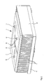
- Fig. 1 shows a dew point cooler 1 comprising two medium circuits through which, as will be explained below with reference to Fig. 7 , a medium, in particular air, can flow in counterflow.
- the dew point cooler 1 comprises a number of heat-conducting and medium-separating walls 2, which are used for heat transfer between the primary air stream and the secondary air stream, with the media remaining separate.
- Fig. 7 for explanation reference should be made to Fig. 7 .
- the walls bear copper or aluminium strips which are bent in the shape of square waves, serve as effective features for increasing the surface area and can be considered as fins.
- These fins are at least partially provided with a porous covering layer, for example consisting of rock wool or a Portland cement. This means that this covering layer is able to retain water which is supplied, for example through capillary action, and to distribute it.
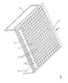
- plastic strips 3 are located on the top side of the walls 2, which strips have acquired the shape shown in Fig. 1 , for example through thermoforming, comprising a row of funnel-like recesses 4 with water-passage openings 5 at the underside.
- the entire dew point cooler is provided with regularly and homogenously distributed funnels on its top side in this way.
- a base 6 At the underside of the dew point cooler 1 there is a base 6, the structure and function of which will be explained in more detail in particular with reference to Figs. 4 and 5 .
- the dew point cooler can be covered by means of a cover 7.
- the cover 7 is composed of two modelled thermoplastic plates 8, 9 placed on top of one another (cf. also Fig. 6 ), which are modelled and attached to one another so as to leave clear a number of water feed lines, namely a common main water feed line 10 and four individual water feed lines 12, 13, 14, 15 which are connected to the main water feed line 10 via a manifold 11 and feed water, which is supplied under pressure via line 10, to four rotating sprinklers 16, 17, 18, 19, respectively.
- a water pipe is connected to the water feed line 10 via a connection 20 by means of a quick-coupling system which is known per se.
- cover 7 is also provided with reinforcing ribs 21, 22, 23, 24.
- the recesses 4 and openings 5 are sized to collect the sprayed water allowing drops to pass through but preventing transmission of tiny droplets.
- the openings may be sized to allow drops of greater than 1 mm to form.
- droplets in the range of 1 to 5 microns, which could possibly transport Legionella bacteria, are prevented from passing through the opening 5 by the formation of the larger drops.
- Fig. 2 shows the dew point cooler 1 in its closed state, in which the cover 7 is positioned in such a manner that it substantially interacts in a sealing manner with the base 6.
- Fig. 4 two side panels 30, 31 are fitted to the base 6.
- the interior of the dew point cooler is visible, since manifolds which are known per se and are used to couple the primary medium passages and the secondary medium passages to one another to form the respective primary and secondary medium inlets and outlets have been omitted from the drawing.
- manifolds which are known per se and are used to couple the primary medium passages and the secondary medium passages to one another to form the respective primary and secondary medium inlets and outlets have been omitted from the drawing.
- the dew point cooler use will generally be made of a configuration as shown in
- Fig. 7 in which the secondary air stream is branched off from the primary air stream which is to be cooled, for example in a ratio of 30%:100%, with the result that 70% of the primary air stream is discharged as cooled air stream.
- This aspect is only of importance with a view to determining the efficiency of the dew point cooler and the nature and shape of the abovementioned manifold.
- the dew point cooler in accordance with the principle outlined in Fig. 7 does not have an external feed for a secondary air stream, since the latter is, after all, branched off internally from the primary air stream at the end of its passage through the dew point cooler.
- Fig. 3 shows a view of the dew point cooler 1 from the other side.
- Fig. 4 shows the base 6.
- the latter together with the side panels 30, 31, is formed integrally from a thermoplastic material.
- the heat-exchanging walls 2 are supported and positioned in recesses 41 and channels 42 which run downwards towards the centre and collect excess water which drips down, passing it to a central drainage channel 43 with the drainage opening 25.
- Fig. 5 shows that the heat-exchanging walls 2 are provided at their ends with a reinforcing profile 44 and that incoming and outgoing air can pass through via the opening 45 shown in Fig. 4 .
- Fig. 7 shows a dew point cooler 50, the casing of which has been omitted for the sake of clarity.
- the dew point cooler in this greatly simplified illustration comprises three heat-conducting and medium-separating walls 51, 52, 53, on either side of which there are respective fins 54, 55, 56, 57 which extend in the form of zigzag-shaped strips in the transverse direction with respect to the streams which are to be described below.
- the fins are of a limited length, while the said walls 51, 52, 53 conduct heat in the region of fins and have heat-insulating parts 58, 58' between the respective strips of fins, which are denoted by 57, 57', 57". This prevents heat transfer in the longitudinal direction, and consequently the exchanger 50 has an excellent efficiency.
- the middle two of the four passages shown correspond to the primary circuit I.
- the various streams and circuits are denoted by the same reference numerals as in Fig. 2 .
- the dew point cooler 50 of Fig. 7 comprises an alternative irrigation device having a removable central water feed line 59 with drop outlets 60 for wetting the fins 54 - 57, which are provided with a covering layer of Portland cement.
- the fins have perforations, with the result that the water coming out of the drop outlets 60 can also wet all of the fins located at a lower level. Any excess water is discharged through means which are not shown.
- the perforations 61 are designed as slots. These slots are not stamped out but rather are formed by the formation of incisions in a stamping machine and pressing the fin material out of the main plane of the surrounding surface, in such a manner that a louvred structure is formed.
- the shape of the perforations 61 which can therefore be referred to as louvres, is such that they are grouped into two groups of louvres which follow one another in the direction of flow and are respectively denoted by 62 and 63.
- the group of louvres located furthest upstream, as seen in the direction of flow is the group denoted by reference numeral 63.
- the louvres are positioned in such a manner that the stream 5 is intercepted by the louvres in order to be diverted to the other side of the fin, where the deflected stream is in turn intercepted once again, by the louvres belonging to group 62, in order to be returned at least approximately to their original path.
- This structure provides excellent heat transfer between the medium flowing past and the fins.
- the water feed line 59 may be arranged to receive water from the funnel-like recesses 4 and water-passage openings 5.
- the nozzles 60 are preferably actuated so as to release water to the coated side, i.e. the fins 54-57 in the secondary medium stream II, intermittently.
- the watering system wets the hydrophilic and water-buffering covering layer. As far as possible, it is prevented from directly humidifying the secondary air stream, since this only has the effect of reducing the efficiency of the dew point cooler 50. Therefore, the use of sprinklers at this location is positively avoided in accordance with the invention.
- the evaporation takes place from the covering layer of the fins, which have been wetted by water, and the free wall parts of the walls 51, 52, 53 which may also be provided with a hydrophilic covering layer, i.e. the fin-free zones denoted by 58 and 58'.
- a drip tray 66 comprising a matrix like array of recesses 68 is provided.
- the recesses are provided with small openings (not shown), by which drops may exit the drip tray 66.
- a cover 70 can be joined to the drip tray 66 to form a substantially sealed unit.
- two rotating sprinklers 72 are supported by the cover 70 so that their outlets can provide a uniform distribution of water to the drip tray 66.
- the drop forming openings at the base of the recesses in the drip forming device have been shown as round openings. Other shapes of openings may also be used.
- elongate slots are effective in allowing rapid delivery of substantially all the water supplied by the sprinklers ensuring abrupt termination of the delivery once the sprinklers are stopped. Slots having dimensions of about 3mm by 16 mm have been found effective in combination with the depicted dew point cooler.
Landscapes
- Engineering & Computer Science (AREA)
- Mechanical Engineering (AREA)
- General Engineering & Computer Science (AREA)
- Chemical & Material Sciences (AREA)
- Combustion & Propulsion (AREA)
- Physics & Mathematics (AREA)
- Thermal Sciences (AREA)
- Life Sciences & Earth Sciences (AREA)
- Sustainable Development (AREA)
- Heat-Exchange Devices With Radiators And Conduit Assemblies (AREA)
- Devices For Blowing Cold Air, Devices For Blowing Warm Air, And Means For Preventing Water Condensation In Air Conditioning Units (AREA)
- Building Environments (AREA)
Claims (14)
- Verdampfungskühler (1) mit einer benetzbaren Wärmeaustauschfläche (54 - 57) und einem Berieselungssystem, wobei das Berieselungssystem umfasst:eine Sprühvorrichtung, um eine Berieselungsflüssigkeit über einem Verteilungsbereich zu verteilen; undeine Tropfenbildungsvorrichtung, um aus der verteilten Flüssigkeit eine Vielzahl von Tropfen zu bilden und die Tropfen vom Verteilungsbereich zur benetzbaren Wärmeaustauschfläche (54 - 57) zuzuführen,wobei es sich bei dem Verteilungsbereich um ein im Wesentlichen geschlossenes Volumen handelt, das einen Austritt zerstäubter Berieselungsflüssigkeit verhindert.
- Verdampfungskühler nach Anspruch 1, wobei die Tropfenbildungsvorrichtung eine Schale (66) mit einer Vielzahl von Öffnungen umfasst.
- Verdampfungskühler nach Anspruch 2, wobei die Schale (66) mit einer Vielzahl von Vertiefungen (68) versehen ist, wobei sich die Öffnungen an den tiefsten Stellen der Vertiefungen befinden.
- Verdampfungskühler nach Anspruch 2 oder Anspruch 3, wobei sich der Verteilungsbereich über der Schale (66) befindet.
- Verdampfungskühler nach einem der vorhergehenden Ansprüche, wobei es sich bei dem Verdampfungskühler um einen Taupunktkühler (50) handelt.
- Verdampfungskühler nach einem der vorhergehenden Ansprüche, wobei die Sprühvorrichtung einen Drehsprühkopf (16 - 19, 72) umfasst.
- Verdampfungskühler nach einem der vorhergehenden Ansprüche, wobei das Berieselungssystem darüber hinaus eine mit der Sprühvorrichtung in Verbindung stehende Druckflüssigkeitsquelle umfasst.
- Verfahren zum Benetzen einer Wärmeaustauschfläche eines Verdampfungskühlers mit einer verdampfbaren Flüssigkeit, Folgendes umfassend:Zuführen der Flüssigkeit zu einem allgemein geschlossenen Verteilungsbereich; undintermittierendes Zustellen der Flüssigkeit vom Verteilungsbereich zur Wärmeaustauschfläche (54 - 57) im Wesentlichen ohne Zerstäubung.
- Verfahren nach Anspruch 8, wobei die Flüssigkeit in den Verteilungsbereich gesprüht wird.
- Verfahren nach Anspruch 8 oder Anspruch 9, wobei die Flüssigkeit aus einer Vielzahl von im Verteilungsbereich ausgebildeten Vertiefungen (68) vom Verteilungsbereich zur Wärmeaustauschfläche zugestellt wird.
- Verfahren nach einem der Ansprüche 8 bis 10, wobei die intermittierende Zustellung einen Betätigungszeitraum umfasst, in der die Flüssigkeitszustellung zur Wärmeaustauschfläche abrupt gestartet und gestoppt wird.
- Verfahren nach Anspruch 11, wobei in einem einzelnen Betätigungszeitraum ausreichend Flüssigkeit zugestellt wird, um die Wärmeaustauschfläche (54 - 57) im Wesentlichen zu sättigen.
- Verfahren nach einem der Ansprüche 8 bis 12, wobei überschüssige Flüssigkeit unter der Wärmeaustauschfläche zur Wiederverwendung aufgefangen wird.
- Verfahren nach einem der Ansprüche 8 bis 13, wobei es sich bei dem Verdampfungskühler um einen Taupunktkühler (50) handelt.
Applications Claiming Priority (3)
| Application Number | Priority Date | Filing Date | Title |
|---|---|---|---|
| NL1022799A NL1022799C2 (nl) | 2003-02-27 | 2003-02-27 | Dauwpuntskoeler met losneembare irrigatiemiddelen. |
| NL1022799 | 2003-02-27 | ||
| PCT/EP2004/001927 WO2004076931A2 (en) | 2003-02-27 | 2004-02-26 | Evaporative cooler |
Publications (2)
| Publication Number | Publication Date |
|---|---|
| EP1599695A2 EP1599695A2 (de) | 2005-11-30 |
| EP1599695B1 true EP1599695B1 (de) | 2014-02-26 |
Family
ID=32923874
Family Applications (1)
| Application Number | Title | Priority Date | Filing Date |
|---|---|---|---|
| EP04714775.6A Expired - Lifetime EP1599695B1 (de) | 2003-02-27 | 2004-02-26 | Verdampfungskühler |
Country Status (14)
| Country | Link |
|---|---|
| US (2) | US7775064B2 (de) |
| EP (1) | EP1599695B1 (de) |
| JP (1) | JP2006519353A (de) |
| KR (1) | KR20050114222A (de) |
| CN (1) | CN1754071B (de) |
| AU (2) | AU2004215180A1 (de) |
| BR (1) | BRPI0407864A (de) |
| CA (1) | CA2517169A1 (de) |
| EA (1) | EA008655B1 (de) |
| MX (1) | MXPA05008971A (de) |
| NL (1) | NL1022799C2 (de) |
| PL (1) | PL377853A1 (de) |
| WO (1) | WO2004076931A2 (de) |
| ZA (1) | ZA200507761B (de) |
Families Citing this family (14)
| Publication number | Priority date | Publication date | Assignee | Title |
|---|---|---|---|---|
| ATE468516T1 (de) * | 2004-02-18 | 2010-06-15 | Idalex Technologies Inc | Plattenmassen- und -wärmetauscher mit randverlängerung |
| GB0622355D0 (en) | 2006-11-09 | 2006-12-20 | Oxycell Holding Bv | High efficiency heat exchanger and dehumidifier |
| AU2008359842B2 (en) * | 2008-07-22 | 2013-05-02 | A.T.E. Enterprises Private Limited | Systems and methods for indirect evaporative cooling and for two stage evaporative cooling |
| US10247483B2 (en) | 2008-09-23 | 2019-04-02 | Oxycom Beheer B.V. | Evaporative cooling device |
| GB0817468D0 (en) * | 2008-09-24 | 2008-10-29 | Univ Nottingham | Cooling system |
| US20110005256A1 (en) * | 2009-07-07 | 2011-01-13 | Gregory T Terry | AC Cooler Device |
| US20120198880A1 (en) * | 2011-02-03 | 2012-08-09 | John Joseph Flaherty | Earthen rock matrix and water-wet bulb temperature cooling mass |
| WO2012145262A1 (en) * | 2011-04-19 | 2012-10-26 | Modine Manufacturing Company | Heat exchanger |
| NL2007827C2 (en) * | 2011-11-21 | 2013-05-23 | Oxycom Beheer Bv | Heat exchange matrix. |
| US11262087B2 (en) | 2017-08-31 | 2022-03-01 | Seeley International Pty Ltd | Evaporative cooler |
| AU2018323065B2 (en) | 2017-08-31 | 2023-09-28 | Seeley International Pty Ltd | Evaporative cooler with pressurized water distribution |
| CN108680045B (zh) * | 2018-06-11 | 2024-03-01 | 湖南元亨科技股份有限公司 | 一种接触兼蒸发式冷却型逆流闭式塔 |
| ES3036643T3 (en) * | 2019-02-26 | 2025-09-23 | Seeley Int Pty Ltd | Pressurized water distribution system for an evaporative cooler |
| CN119123857B (zh) * | 2024-11-12 | 2025-03-04 | 湖南奔骥环保能源科技有限责任公司 | 一种具有顶部间接性喷淋装置的冷却器 |
Family Cites Families (51)
| Publication number | Priority date | Publication date | Assignee | Title |
|---|---|---|---|---|
| DE1100053B (de) | 1959-09-04 | 1961-02-23 | Escher Wyss Gmbh | Fluessigkeitsverteileinrichtung fuer Rieselapparate |
| US3290866A (en) * | 1964-08-26 | 1966-12-13 | Schonrock Verlie | Evaporative cooler |
| FR1489861A (fr) | 1966-06-17 | 1967-07-28 | Appareil de contact gaz-liquides | |
| FR1581810A (de) * | 1968-08-08 | 1969-09-19 | ||
| SE333631B (de) * | 1969-07-17 | 1971-03-22 | C Munters | |
| US3583174A (en) * | 1969-10-23 | 1971-06-08 | Wilson J Logue | Evaporative air cooler for vehicle cabs |
| US5192355A (en) * | 1975-05-27 | 1993-03-09 | Kamterter Products, Inc. | Manufacturing and using nitrogen fertilizer solutions on a farm |
| US4023949A (en) * | 1975-08-04 | 1977-05-17 | Schlom Leslie A | Evaporative refrigeration system |
| US4158679A (en) * | 1978-02-22 | 1979-06-19 | General Filters, Inc. | Water distributor trough primarily for a warm air furnace mounted humidifier |
| US4201262A (en) * | 1978-08-07 | 1980-05-06 | Goldstein Stanley A | Cooler for chilling a working fluid |
| US4419300A (en) * | 1980-03-03 | 1983-12-06 | General Texas Corporation | Non-corrosive, non-staining evaporative cooler |
| US4479366A (en) | 1982-04-26 | 1984-10-30 | Rli, Inc. | Evaporative cooler |
| JPS5938588A (ja) * | 1982-08-30 | 1984-03-02 | Toyota Motor Corp | 熱交換器 |
| US4674295A (en) * | 1983-03-14 | 1987-06-23 | Curtis Sr Thad C | Evaporative air conditioner and method |
| US4612778A (en) * | 1985-02-14 | 1986-09-23 | Medrano Michael V | Precooler for an evaporative cooler |
| US4657709A (en) * | 1985-10-30 | 1987-04-14 | Goettl Adam D | Water distribution trough for evaporative cooler pad |
| US4660390A (en) * | 1986-03-25 | 1987-04-28 | Worthington Mark N | Air conditioner with three stages of indirect regeneration |
| US4994211A (en) * | 1989-09-05 | 1991-02-19 | Fuller Joe W | Water distribution apparatus for evaporative cooling system |
| JP2766694B2 (ja) * | 1989-12-28 | 1998-06-18 | 株式会社竹中工務店 | 冷却塔の冷却水飛散防止装置 |
| US5003789A (en) * | 1990-03-01 | 1991-04-02 | Manuel Gaona | Mist air conditioner for evaporative cooler |
| US5349829A (en) * | 1992-05-21 | 1994-09-27 | Aoc, Inc. | Method and apparatus for evaporatively cooling gases and/or fluids |
| JP2512852B2 (ja) * | 1992-07-16 | 1996-07-03 | 鹿島建設株式会社 | 製氷用の冷媒 |
| US5509565A (en) * | 1993-04-16 | 1996-04-23 | Hoffman; William D. | Foam cap for evaporative coolers |
| US5377500A (en) * | 1993-06-03 | 1995-01-03 | Fast Maker Enterprise Co., Ltd. | Water cooled air conditioner |
| DE29506110U1 (de) | 1995-01-20 | 1995-08-17 | Polybloc Ag, Winterthur | Plattenwärmeaustauscher mit Benetzungseinrichtung |
| US5606868A (en) * | 1995-03-06 | 1997-03-04 | General Shelters Of Texas S.B., Inc. | Reticulated foam sleeve for evaporative cooling unit spray conduit |
| US6018954A (en) * | 1995-04-20 | 2000-02-01 | Assaf; Gad | Heat pump system and method for air-conditioning |
| EP0773412B1 (de) * | 1995-11-07 | 2003-12-17 | Kabushiki Kaisha Seibu Giken | Verfahren und Vorrichtung zum Kühlen eines Fluidstromes und trocknende Gaskühlung |
| JP3033952B2 (ja) * | 1996-11-06 | 2000-04-17 | 茂 長野 | 冷却塔 |
| AUPO562597A0 (en) * | 1997-03-12 | 1997-04-10 | Brivis Australia Pty Ltd | Evaporative air conditioner |
| US5851444A (en) * | 1997-03-13 | 1998-12-22 | Skuttle Manufacturing Company | Air-treating apparatus having improved water distribution tray |
| US6102994A (en) * | 1997-03-20 | 2000-08-15 | Alliedsignal Inc. | Alumina-based hydrophilic antimicrobial coating |
| US5857350A (en) * | 1997-04-14 | 1999-01-12 | Johnson; Robert Edwin | Evaporative cooling device |
| US5853625A (en) | 1997-06-27 | 1998-12-29 | Honeywell Inc. | Water distribution tray for a pad-type humidifier unit |
| US5971370A (en) | 1998-01-15 | 1999-10-26 | Munters Corporation | Integrated water distribution/cooling pad system |
| WO1999041552A1 (en) * | 1998-02-13 | 1999-08-19 | Antonius Van Hecke | Method and device for cooling air |
| US5946932A (en) * | 1998-06-03 | 1999-09-07 | Wang; Huai-Wei | Multistage condensing structure |
| JP3682615B2 (ja) * | 1999-03-30 | 2005-08-10 | 三菱電機株式会社 | 加湿装置 |
| CA2312402C (en) * | 1999-07-06 | 2007-09-04 | Cherif Menassa | Flow-through humidifier |
| BE1013160A6 (nl) * | 1999-11-30 | 2001-10-02 | Offringa Dirk Dooitze | Werkwijze en inrichting voor het koelen van lucht. |
| US6497107B2 (en) * | 2000-07-27 | 2002-12-24 | Idalex Technologies, Inc. | Method and apparatus of indirect-evaporation cooling |
| TW445360B (en) * | 2000-08-02 | 2001-07-11 | Nutec Electrical Eng Co Ltd | Air-conditioning apparatus with evaporative type condenser |
| CN100380082C (zh) * | 2000-09-27 | 2008-04-09 | 埃达雷克斯技术公司 | 用于露点蒸发冷却器的方法和板设备 |
| US6463751B1 (en) * | 2000-11-09 | 2002-10-15 | Kevin Teller | AC system utilizing condensate water to precool hot gas |
| KR100409265B1 (ko) * | 2001-01-17 | 2003-12-18 | 한국과학기술연구원 | 재생형 증발식 냉방기 |
| US6367277B1 (en) * | 2001-04-10 | 2002-04-09 | Stephen W. Kinkel | Evaporative cooling apparatus |
| US6572085B2 (en) * | 2001-05-15 | 2003-06-03 | Research Products Corporation | Humidifier with reversible housing and distribution tray overflow |
| US6748759B2 (en) * | 2001-08-02 | 2004-06-15 | Ho-Hsin Wu | High efficiency heat exchanger |
| NL1018735C1 (nl) * | 2001-08-10 | 2003-02-11 | Forest Air B V | Enthalpie-uitwisselaar. |
| US6854278B2 (en) * | 2001-08-20 | 2005-02-15 | Valeriy Maisotsenko | Method of evaporative cooling of a fluid and apparatus therefor |
| NL1021812C1 (nl) * | 2002-04-26 | 2003-10-28 | Oxycell Holding Bv | Dauwpuntskoeler. |
-
2003
- 2003-02-27 NL NL1022799A patent/NL1022799C2/nl not_active IP Right Cessation
-
2004
- 2004-02-26 US US10/546,836 patent/US7775064B2/en not_active Expired - Lifetime
- 2004-02-26 KR KR1020057016005A patent/KR20050114222A/ko not_active Ceased
- 2004-02-26 AU AU2004215180A patent/AU2004215180A1/en not_active Abandoned
- 2004-02-26 PL PL377853A patent/PL377853A1/pl not_active Application Discontinuation
- 2004-02-26 MX MXPA05008971A patent/MXPA05008971A/es active IP Right Grant
- 2004-02-26 WO PCT/EP2004/001927 patent/WO2004076931A2/en not_active Ceased
- 2004-02-26 EA EA200501365A patent/EA008655B1/ru not_active IP Right Cessation
- 2004-02-26 CA CA002517169A patent/CA2517169A1/en not_active Abandoned
- 2004-02-26 JP JP2006501962A patent/JP2006519353A/ja active Pending
- 2004-02-26 EP EP04714775.6A patent/EP1599695B1/de not_active Expired - Lifetime
- 2004-02-26 BR BRPI0407864-0A patent/BRPI0407864A/pt not_active IP Right Cessation
- 2004-02-26 CN CN2004800050024A patent/CN1754071B/zh not_active Expired - Fee Related
-
2005
- 2005-09-26 ZA ZA200507761A patent/ZA200507761B/en unknown
-
2010
- 2010-06-04 AU AU2010202350A patent/AU2010202350A1/en not_active Abandoned
- 2010-07-22 US US12/841,382 patent/US20110041531A1/en not_active Abandoned
Also Published As
| Publication number | Publication date |
|---|---|
| CN1754071B (zh) | 2010-05-05 |
| US7775064B2 (en) | 2010-08-17 |
| WO2004076931A3 (en) | 2004-10-28 |
| US20060070390A1 (en) | 2006-04-06 |
| AU2004215180A1 (en) | 2004-09-10 |
| AU2010202350A1 (en) | 2010-07-01 |
| US20110041531A1 (en) | 2011-02-24 |
| CN1754071A (zh) | 2006-03-29 |
| JP2006519353A (ja) | 2006-08-24 |
| EA008655B1 (ru) | 2007-06-29 |
| MXPA05008971A (es) | 2005-11-04 |
| EP1599695A2 (de) | 2005-11-30 |
| NL1022799C2 (nl) | 2004-08-30 |
| BRPI0407864A (pt) | 2006-03-01 |
| WO2004076931A2 (en) | 2004-09-10 |
| EA200501365A1 (ru) | 2006-02-24 |
| ZA200507761B (en) | 2007-07-25 |
| KR20050114222A (ko) | 2005-12-05 |
| CA2517169A1 (en) | 2004-09-10 |
| PL377853A1 (pl) | 2006-02-20 |
Similar Documents
| Publication | Publication Date | Title |
|---|---|---|
| US20110041531A1 (en) | Evaporative cooler | |
| US5349829A (en) | Method and apparatus for evaporatively cooling gases and/or fluids | |
| AU2009316228B2 (en) | Indirect evaporative cooler construction | |
| US6523604B1 (en) | Indirect evaporative cooling apparatus | |
| EP1836046B1 (de) | Verfahren und materialien zur verbesserung von verdunstungswärmetauschern | |
| US20030230092A1 (en) | Air conditioning system | |
| TWI665423B (zh) | 冷卻塔水分配系統 | |
| KR20080039457A (ko) | 파이프 내에서 순환하는 유체의 냉각을 위한 방열기 | |
| US7021608B2 (en) | Distributor for micro-quantities of liquid | |
| US20110232315A1 (en) | Regenerative evaporative cooler, cooling system and core module thereof | |
| WO2018051157A1 (en) | Water distribution systems for plate heat and mass exchanger for indirect evaportive cooling | |
| RU2073174C1 (ru) | Установка для косвенно-испарительного охлаждения воздуха | |
| WO1999041552A1 (en) | Method and device for cooling air | |
| HK1090114A (en) | Evaporative cooler | |
| RU2079058C1 (ru) | Кондиционер | |
| AU2010201392B2 (en) | Method and Means for Operating Evaporative Coolers | |
| RU2232367C1 (ru) | Градирня | |
| JP3171462U (ja) | 間接気化式冷却装置の給水機構 | |
| SU1113641A1 (ru) | Устройство косвенно-испарительного охлаждени воздуха | |
| RU2045728C1 (ru) | Вентиляторная градирня | |
| JPH02267492A (ja) | 白煙防止冷却塔 |
Legal Events
| Date | Code | Title | Description |
|---|---|---|---|
| PUAI | Public reference made under article 153(3) epc to a published international application that has entered the european phase |
Free format text: ORIGINAL CODE: 0009012 |
|
| 17P | Request for examination filed |
Effective date: 20050916 |
|
| AK | Designated contracting states |
Kind code of ref document: A2 Designated state(s): AT BE BG CH CY CZ DE DK EE ES FI FR GB GR HU IE IT LI LU MC NL PT RO SE SI SK TR |
|
| AX | Request for extension of the european patent |
Extension state: AL LT LV MK |
|
| DAX | Request for extension of the european patent (deleted) | ||
| 111Z | Information provided on other rights and legal means of execution |
Free format text: ATBEBGCHCYCZDEDKEEESFIFRGBGRHUIEITLUMCNLPTROSESISKTR Effective date: 20061122 |
|
| RAP1 | Party data changed (applicant data changed or rights of an application transferred) |
Owner name: OXYCOM BEHEER B.V. |
|
| 111Z | Information provided on other rights and legal means of execution |
Free format text: AT BE BG CH CY CZ DE DK EE ES FI FR GB GR HU IE IT LU MC NL PT RO SE SI SK TR Effective date: 20071121 Free format text: AT BE BG CH CY CZ DE DK EE ES FI FR GB GR HU IE IT LU MC NL PT RO SE SI SK TR Effective date: 20061122 |
|
| RAP1 | Party data changed (applicant data changed or rights of an application transferred) |
Owner name: OXYCOM BEHEER B.V. |
|
| 17Q | First examination report despatched |
Effective date: 20111230 |
|
| GRAP | Despatch of communication of intention to grant a patent |
Free format text: ORIGINAL CODE: EPIDOSNIGR1 |
|
| INTG | Intention to grant announced |
Effective date: 20130510 |
|
| GRAS | Grant fee paid |
Free format text: ORIGINAL CODE: EPIDOSNIGR3 |
|
| GRAA | (expected) grant |
Free format text: ORIGINAL CODE: 0009210 |
|
| AK | Designated contracting states |
Kind code of ref document: B1 Designated state(s): AT BE BG CH CY CZ DE DK EE ES FI FR GB GR HU IE IT LI LU MC NL PT RO SE SI SK TR |
|
| REG | Reference to a national code |
Ref country code: GB Ref legal event code: FG4D |
|
| REG | Reference to a national code |
Ref country code: CH Ref legal event code: EP |
|
| REG | Reference to a national code |
Ref country code: AT Ref legal event code: REF Ref document number: 653841 Country of ref document: AT Kind code of ref document: T Effective date: 20140315 |
|
| REG | Reference to a national code |
Ref country code: DE Ref legal event code: R096 Ref document number: 602004044440 Country of ref document: DE Effective date: 20140403 |
|
| REG | Reference to a national code |
Ref country code: IE Ref legal event code: FG4D |
|
| REG | Reference to a national code |
Ref country code: NL Ref legal event code: T3 |
|
| REG | Reference to a national code |
Ref country code: CH Ref legal event code: NV Representative=s name: FIAMMENGHI-FIAMMENGHI, CH |
|
| PG25 | Lapsed in a contracting state [announced via postgrant information from national office to epo] |
Ref country code: FI Free format text: LAPSE BECAUSE OF FAILURE TO SUBMIT A TRANSLATION OF THE DESCRIPTION OR TO PAY THE FEE WITHIN THE PRESCRIBED TIME-LIMIT Effective date: 20140226 Ref country code: CY Free format text: LAPSE BECAUSE OF FAILURE TO SUBMIT A TRANSLATION OF THE DESCRIPTION OR TO PAY THE FEE WITHIN THE PRESCRIBED TIME-LIMIT Effective date: 20140226 Ref country code: SE Free format text: LAPSE BECAUSE OF FAILURE TO SUBMIT A TRANSLATION OF THE DESCRIPTION OR TO PAY THE FEE WITHIN THE PRESCRIBED TIME-LIMIT Effective date: 20140226 Ref country code: PT Free format text: LAPSE BECAUSE OF FAILURE TO SUBMIT A TRANSLATION OF THE DESCRIPTION OR TO PAY THE FEE WITHIN THE PRESCRIBED TIME-LIMIT Effective date: 20140626 |
|
| PG25 | Lapsed in a contracting state [announced via postgrant information from national office to epo] |
Ref country code: DK Free format text: LAPSE BECAUSE OF FAILURE TO SUBMIT A TRANSLATION OF THE DESCRIPTION OR TO PAY THE FEE WITHIN THE PRESCRIBED TIME-LIMIT Effective date: 20140226 Ref country code: RO Free format text: LAPSE BECAUSE OF FAILURE TO SUBMIT A TRANSLATION OF THE DESCRIPTION OR TO PAY THE FEE WITHIN THE PRESCRIBED TIME-LIMIT Effective date: 20140226 Ref country code: EE Free format text: LAPSE BECAUSE OF FAILURE TO SUBMIT A TRANSLATION OF THE DESCRIPTION OR TO PAY THE FEE WITHIN THE PRESCRIBED TIME-LIMIT Effective date: 20140226 Ref country code: CZ Free format text: LAPSE BECAUSE OF FAILURE TO SUBMIT A TRANSLATION OF THE DESCRIPTION OR TO PAY THE FEE WITHIN THE PRESCRIBED TIME-LIMIT Effective date: 20140226 |
|
| REG | Reference to a national code |
Ref country code: DE Ref legal event code: R097 Ref document number: 602004044440 Country of ref document: DE |
|
| PG25 | Lapsed in a contracting state [announced via postgrant information from national office to epo] |
Ref country code: ES Free format text: LAPSE BECAUSE OF FAILURE TO SUBMIT A TRANSLATION OF THE DESCRIPTION OR TO PAY THE FEE WITHIN THE PRESCRIBED TIME-LIMIT Effective date: 20140226 Ref country code: SK Free format text: LAPSE BECAUSE OF FAILURE TO SUBMIT A TRANSLATION OF THE DESCRIPTION OR TO PAY THE FEE WITHIN THE PRESCRIBED TIME-LIMIT Effective date: 20140226 |
|
| REG | Reference to a national code |
Ref country code: IE Ref legal event code: MM4A |
|
| PLBE | No opposition filed within time limit |
Free format text: ORIGINAL CODE: 0009261 |
|
| STAA | Information on the status of an ep patent application or granted ep patent |
Free format text: STATUS: NO OPPOSITION FILED WITHIN TIME LIMIT |
|
| GBPC | Gb: european patent ceased through non-payment of renewal fee |
Effective date: 20140526 |
|
| PG25 | Lapsed in a contracting state [announced via postgrant information from national office to epo] |
Ref country code: IE Free format text: LAPSE BECAUSE OF NON-PAYMENT OF DUE FEES Effective date: 20140226 |
|
| 26N | No opposition filed |
Effective date: 20141127 |
|
| REG | Reference to a national code |
Ref country code: FR Ref legal event code: ST Effective date: 20150115 |
|
| REG | Reference to a national code |
Ref country code: DE Ref legal event code: R097 Ref document number: 602004044440 Country of ref document: DE Effective date: 20141127 |
|
| PG25 | Lapsed in a contracting state [announced via postgrant information from national office to epo] |
Ref country code: IT Free format text: LAPSE BECAUSE OF FAILURE TO SUBMIT A TRANSLATION OF THE DESCRIPTION OR TO PAY THE FEE WITHIN THE PRESCRIBED TIME-LIMIT Effective date: 20140226 |
|
| PGFP | Annual fee paid to national office [announced via postgrant information from national office to epo] |
Ref country code: LU Payment date: 20150304 Year of fee payment: 12 Ref country code: NL Payment date: 20150227 Year of fee payment: 12 Ref country code: CH Payment date: 20150319 Year of fee payment: 12 |
|
| PG25 | Lapsed in a contracting state [announced via postgrant information from national office to epo] |
Ref country code: SI Free format text: LAPSE BECAUSE OF FAILURE TO SUBMIT A TRANSLATION OF THE DESCRIPTION OR TO PAY THE FEE WITHIN THE PRESCRIBED TIME-LIMIT Effective date: 20140226 Ref country code: FR Free format text: LAPSE BECAUSE OF NON-PAYMENT OF DUE FEES Effective date: 20140428 Ref country code: GB Free format text: LAPSE BECAUSE OF NON-PAYMENT OF DUE FEES Effective date: 20140526 |
|
| PGFP | Annual fee paid to national office [announced via postgrant information from national office to epo] |
Ref country code: AT Payment date: 20150311 Year of fee payment: 12 |
|
| PGFP | Annual fee paid to national office [announced via postgrant information from national office to epo] |
Ref country code: BE Payment date: 20150227 Year of fee payment: 12 |
|
| PG25 | Lapsed in a contracting state [announced via postgrant information from national office to epo] |
Ref country code: MC Free format text: LAPSE BECAUSE OF FAILURE TO SUBMIT A TRANSLATION OF THE DESCRIPTION OR TO PAY THE FEE WITHIN THE PRESCRIBED TIME-LIMIT Effective date: 20140226 |
|
| PG25 | Lapsed in a contracting state [announced via postgrant information from national office to epo] |
Ref country code: BE Free format text: LAPSE BECAUSE OF NON-PAYMENT OF DUE FEES Effective date: 20160229 Ref country code: BG Free format text: LAPSE BECAUSE OF FAILURE TO SUBMIT A TRANSLATION OF THE DESCRIPTION OR TO PAY THE FEE WITHIN THE PRESCRIBED TIME-LIMIT Effective date: 20140226 |
|
| PG25 | Lapsed in a contracting state [announced via postgrant information from national office to epo] |
Ref country code: GR Free format text: LAPSE BECAUSE OF FAILURE TO SUBMIT A TRANSLATION OF THE DESCRIPTION OR TO PAY THE FEE WITHIN THE PRESCRIBED TIME-LIMIT Effective date: 20140527 |
|
| PG25 | Lapsed in a contracting state [announced via postgrant information from national office to epo] |
Ref country code: HU Free format text: LAPSE BECAUSE OF FAILURE TO SUBMIT A TRANSLATION OF THE DESCRIPTION OR TO PAY THE FEE WITHIN THE PRESCRIBED TIME-LIMIT; INVALID AB INITIO Effective date: 20040226 Ref country code: TR Free format text: LAPSE BECAUSE OF FAILURE TO SUBMIT A TRANSLATION OF THE DESCRIPTION OR TO PAY THE FEE WITHIN THE PRESCRIBED TIME-LIMIT Effective date: 20140226 |
|
| PG25 | Lapsed in a contracting state [announced via postgrant information from national office to epo] |
Ref country code: LU Free format text: LAPSE BECAUSE OF NON-PAYMENT OF DUE FEES Effective date: 20160226 |
|
| REG | Reference to a national code |
Ref country code: CH Ref legal event code: PL |
|
| REG | Reference to a national code |
Ref country code: AT Ref legal event code: MM01 Ref document number: 653841 Country of ref document: AT Kind code of ref document: T Effective date: 20160226 |
|
| PG25 | Lapsed in a contracting state [announced via postgrant information from national office to epo] |
Ref country code: CH Free format text: LAPSE BECAUSE OF NON-PAYMENT OF DUE FEES Effective date: 20160229 Ref country code: LI Free format text: LAPSE BECAUSE OF NON-PAYMENT OF DUE FEES Effective date: 20160229 |
|
| REG | Reference to a national code |
Ref country code: NL Ref legal event code: MM Effective date: 20160301 |
|
| PG25 | Lapsed in a contracting state [announced via postgrant information from national office to epo] |
Ref country code: AT Free format text: LAPSE BECAUSE OF NON-PAYMENT OF DUE FEES Effective date: 20160226 |
|
| PG25 | Lapsed in a contracting state [announced via postgrant information from national office to epo] |
Ref country code: NL Free format text: LAPSE BECAUSE OF NON-PAYMENT OF DUE FEES Effective date: 20160301 |
|
| REG | Reference to a national code |
Ref country code: DE Ref legal event code: R082 Ref document number: 602004044440 Country of ref document: DE Representative=s name: KILBURN & STRODE LLP, NL |
|
| PGFP | Annual fee paid to national office [announced via postgrant information from national office to epo] |
Ref country code: DE Payment date: 20220217 Year of fee payment: 19 |
|
| REG | Reference to a national code |
Ref country code: DE Ref legal event code: R119 Ref document number: 602004044440 Country of ref document: DE |
|
| PG25 | Lapsed in a contracting state [announced via postgrant information from national office to epo] |
Ref country code: DE Free format text: LAPSE BECAUSE OF NON-PAYMENT OF DUE FEES Effective date: 20230901 |