EP1598792B1 - Sicherheitssystem und -methode mit Infrarotstrahlen - Google Patents
Sicherheitssystem und -methode mit Infrarotstrahlen Download PDFInfo
- Publication number
- EP1598792B1 EP1598792B1 EP05010799A EP05010799A EP1598792B1 EP 1598792 B1 EP1598792 B1 EP 1598792B1 EP 05010799 A EP05010799 A EP 05010799A EP 05010799 A EP05010799 A EP 05010799A EP 1598792 B1 EP1598792 B1 EP 1598792B1
- Authority
- EP
- European Patent Office
- Prior art keywords
- region
- image
- space
- detectors
- safety
- Prior art date
- Legal status (The legal status is an assumption and is not a legal conclusion. Google has not performed a legal analysis and makes no representation as to the accuracy of the status listed.)
- Ceased
Links
Images


Classifications
-
- F—MECHANICAL ENGINEERING; LIGHTING; HEATING; WEAPONS; BLASTING
- F16—ENGINEERING ELEMENTS AND UNITS; GENERAL MEASURES FOR PRODUCING AND MAINTAINING EFFECTIVE FUNCTIONING OF MACHINES OR INSTALLATIONS; THERMAL INSULATION IN GENERAL
- F16P—SAFETY DEVICES IN GENERAL; SAFETY DEVICES FOR PRESSES
- F16P3/00—Safety devices acting in conjunction with the control or operation of a machine; Control arrangements requiring the simultaneous use of two or more parts of the body
- F16P3/12—Safety devices acting in conjunction with the control or operation of a machine; Control arrangements requiring the simultaneous use of two or more parts of the body with means, e.g. feelers, which in case of the presence of a body part of a person in or near the danger zone influence the control or operation of the machine
- F16P3/14—Safety devices acting in conjunction with the control or operation of a machine; Control arrangements requiring the simultaneous use of two or more parts of the body with means, e.g. feelers, which in case of the presence of a body part of a person in or near the danger zone influence the control or operation of the machine the means being photocells or other devices sensitive without mechanical contact
- F16P3/142—Safety devices acting in conjunction with the control or operation of a machine; Control arrangements requiring the simultaneous use of two or more parts of the body with means, e.g. feelers, which in case of the presence of a body part of a person in or near the danger zone influence the control or operation of the machine the means being photocells or other devices sensitive without mechanical contact using image capturing devices
-
- H—ELECTRICITY
- H04—ELECTRIC COMMUNICATION TECHNIQUE
- H04N—PICTORIAL COMMUNICATION, e.g. TELEVISION
- H04N7/00—Television systems
- H04N7/18—Closed-circuit television [CCTV] systems, i.e. systems in which the video signal is not broadcast
- H04N7/181—Closed-circuit television [CCTV] systems, i.e. systems in which the video signal is not broadcast for receiving images from a plurality of remote sources
Definitions
- the present invention relates generally to industrial control systems, and more particularly to a system and methodology that projects electromagnetic energy into a region in order to determine an intrusion of people or objects in the region, wherein the determination is based upon a detection of an interruption in the electromagnetic energy.
- Many safety systems operate on the principal of first determining what type of object is within a region then potentially disabling some device after the determination. For example, many systems within the infrared safety domain utilize techniques that combine images then analyze the combined image via pixel spectral power, density and/or threshold values. Other techniques include measuring thermal properties; measuring moving surfaces (reflectivity, smoothness, and so forth.); and techniques utilized to determine position. The following provides a brief description and examples of some current implementations that employ one or more of the above techniques.
- One example includes a remote sensing system for real time monitoring of patient position which can report variations in patient setup from day to day as well as motion during individual treatments.
- this type system includes: (a) a source of radiation for applying radiation to a patient; (b) targets affixed to the patient for reflecting radiation impinging thereon; (c) two cameras and a computer for detecting the reflected radiation and for determining the current position of the targets in three-dimensional space; (d) a data store for storing the position of the targets; (e) the computer also serving to compare the current position of the targets with positions stored in the data store; and (f) a display for displaying indicators whenever differences between the current position and the stored position exceed tolerances stored in the data store.
- This type of system employs reflected radiation for determining the position of a person.
- Another example includes a system for detecting presence and/or motion of a person or other movable entity within a selected space. Detection is accomplished by detecting reflected light or other radiation from the space, presence being signified when detected radiation differs from an established background, either up or down, by an amount exceeding a predetermined threshold. Blending of the entity with the background is avoided by viewing the entity at least two different angles with different backgrounds, for example by use of two spaced detectors, and variations in background are automatically compensated for when a presence indication persists for a selected period of time after the last motion indication is received. The background is updated to the current level when this occurs.
- light sources are structured to irradiate substantially the entire space and saturation of a detector by ambient radiation is avoided by providing a band-pass filter which passes only radiation in a narrow overlap wavelength band for the radiation sources and detectors.
- This type system operates by analyzing reflected radiation from the space, wherein differences in the reflected radiation are detected.
- a system in yet another example, includes an infrared detector having two cameras for viewing a scene to detect humans.
- the cameras focus the scene on respective pixel arrays.
- One array is designed with a filter to be sensitive to light from 0.8 to 1.4 microns and the array of the other camera is designed with a filter to be sensitive from 1.4 microns to 2.2 microns.
- the arrays are co-registered spacially and temporally relative to the viewed scene and pixel transmission dynamics.
- the spectral powers of the pixels from both arrays are difference weighted and fused into one set of pixels.
- the fused pixels are thresholded into another set of pixels that have one of two values--black or white. These pixels are entered into a visual display that shows a segment image of a human if in the viewed scene.
- This type system employs image processing techniques that analyzes spectral densities associated with pixels.
- Another system includes a camera arrangement for detecting an object such as a driver or a child seat located on, above or in front of a vehicle seat.
- the system includes a camera for creating an image of any object in that position, and also includes an electromagnetic wave source such as an infrared light source.
- An image created with the source operational is stored in a first store and an image created with the source non-operational is stored in a second store.
- the stored images are then subtracted and any object in the subtraction image is identified by an image processor.
- the position of the object may also be determined and used to inhibit or modify the operation of a safety device such as an airbag in the vehicle.
- This type of system identifies an object by digital subtraction of images taken before and after illumination by a source.
- the US 2002/125435 A1 discloses an object detection system in which a monitored area is illuminated through a patterned grating, so as to produce a pattern of interference fringes, including a dynamic moiré pattern.
- the projected pattern can include light and dark areas, e.g. a striped or checkerboard pattern.
- a comparison is performed between a reference image and a live image by subtracting one image from the other to detect shifts or deformations that would indicate entry or movement of an object into the monitored area.
- the images are compared to calculate a difference in brightness levels of light areas and dark areas of a mask window.
- the US-B1-6 297 844 discloses a 3-D machine vision system that uses multiple stereoscopic cameras to record three-dimensional points in a "training" scene (i.e. a reference image) and a "ran-time” scene. A comparison is made of the sets of 3-D points to calculate the position of an "intruder object,” which would be in the run-time scene, indicated by a distance different from the objects in the training scene. (See, e. g, col. 4, lines 3-29).
- the present invention relates to a system and methodology that projects electromagnetic energy into a region (or regions) in order to determine an intrusion of people or objects in the region.
- the determination is based upon a detection of whether or not an interruption has occurred within the region as opposed to positively identifying what may have actually entered into the region.
- indications of intrusion can be made in a straightforward, reliable, economical, and highly robust manner by detecting the absence of energy rather than attempting to resolve or compute items within an image.
- an output device may be employed to disable equipment operating in or near the region in order to protect people or objects that may have entered the region.
- a notification may be sent or logged for further analysis indicating that an intrusion has occurred.
- one or more projectors direct electromagnetic energy (e.g., infrared spectrum images) into an area or region designated as a security or safety zone.
- One or more cameras or digital detectors record an image from the energized region during a period when only allowed objects (or no objects) are in the region.
- a space designated as a security zone may contain zero or more objects that normally occupy such space.
- the captured image from the space of allowed items (or no items) within the space is then stored by a processor. As time goes by, the processor and detector capture current images from the space at predetermined intervals.
- the processor After capturing a current image, the processor compares the current image with the previously stored image that contains allowed items. If an intrusion has occurred, portions of energy received by the detector is blocked or shielded from reaching the detector by the intruding device or person. Thus, after image comparison (e.g., digital subtraction of images), the processor detects a shadow (e.g., pixels not energized) in the current image, wherein such detection can then trigger further actions. For example, if a shadow or energy blockage is detected, hazardous equipment can be disabled or other events can be triggered such as sounding a warning. Other aspects include employment of multiple cameras for detecting differences with stored images, wherein differences detected by any of the cameras can trigger further actions. Also, multi-camera arrangements can be employed for three-dimensional reconstructions of an area for detecting objects or people therein.
- the present invention relates to a system and methodology facilitating automated intrusion detection within a region of space in an industrial controller environment.
- An automated safety system is provided having at least one projector to direct electromagnetic energy into a region of space associated with a security, warning, or safety zone.
- a detector or detectors senses an interruption of the electromagnetic energy in the region of space by an object or person that may enter the space.
- the system includes a processor and a storage component, wherein the processor determines the interruption by comparing a current image from the detector with a previously stored image in the storage component.
- the processor Upon detection, the processor triggers an event based upon the comparison, whereby the event includes such aspects as activating an output, de-energizing a machine, sounding a warning, sounding an alarm, storing data associated with the event, and sending a notification to a local or a remote system, for example.
- the processor and associated projector/detector can project/construct two-dimensional images or three-dimensional images in order to determine the interruption.
- a component may be, but is not limited to being, a process running on a processor, a processor, an object, an executable, a thread of execution, a program and a computer.
- an application running on a server and the server can be components.
- One or more components may reside within a process and/or thread of execution and a component may be localized on one computer and/or distributed between two or more computers ( e . g ., via data packets and signals between the computers), industrial controllers, and/or modules communicating therewith.
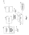
- a system 100 illustrates an automated safety system in accordance with an aspect of the present invention.
- the system 100 includes one or more projectors 110 that direct electromagnetic energy 120 (e.g., infrared spectrum images) into an area or region 130 designated as a security or safety zone.
- electromagnetic energy 120 e.g., infrared spectrum images
- infrared radiation or energy 120 is selected since this type of radiation is invisible to the human eye.
- other frequencies such as visible frequencies may be employed.
- One or more cameras or digital detectors 140 record an image 150 from the energized region 130 during a period when only allowed objects (or no objects) are in the region.
- the region 130 can be allocated as a security zone that may contain zero or more objects that normally occupy the region.
- the captured image 150 from the space of allowed items (or no items) within the region 130 is then stored by a processor 160 having associated memory components and respective processor support components.
- the processor 160 and detector 140 capture current images 150 from the region 130 at predetermined intervals (e.g., at 10 or 20 hertz intervals).
- the processor 160 After capturing a current image 150, the processor 160 compares the current image with the previously stored image that contains allowed items. If an intrusion has occurred in the region 130, portions of energy received by the detector 140 is blocked or shielded from reaching the detector 140 by the intruding device or person. It is noted that intrusions may occur from substantially any direction into the region 130 as illustrated at 180 (e.g., up, down, left, right, from an angle and so forth). Thus, after image comparison ( e . g ., digital subtraction of images), the processor 160 detects a shadow ( e . g ., pixels not energized or lightly energized) in the current image 150, wherein such detection can then trigger further actions.
- a shadow e . g ., pixels not energized or lightly energized
- hazardous equipment can be disabled or other events can be triggered at 170 by the processor 160 such as sounding a warning or sending a notification (e.g. , electronic message, e-mail).
- a notification e.g. , electronic message, e-mail
- thresholds can be set up in the processor 160 to make intrusion determinations (e.g. , more than three pixels having lower returned energy, fire an event).
- the system 100 can be employed in various applications that are designed to facilitate safety in an industrial environment.
- the system 100 can be employed as an Infrared Safety Camera targeted for applications in which a machine or installation can be stopped in any position in its production cycle. This can include machine stoppage via the event 170 which can trigger an output device such as a relay, for example.
- the system 100 is typically not employed to safeguard installations with rundown time or end-of cycle applications. Examples of safety applications (e.g., where machines are shut down upon detecting intrusion) include: robotic cells (welding, assembly), packaging machines, large machine entrances, hot storages such as in foundries, and so forth.
- This system 100 can also apply to the following example industries:
- the system 200 includes an Infrared Safety Camera 210 providing two PNP safety outputs 220 that drive a safety relay 230 having associated contacts 240.
- the Infrared Safety Camera 220 can be designed to safeguard man and machine against hazards through moving parts and stored energy.
- the Infrared Safety Camera 220 can be part of a safety system 200 in which the Infrared Safety Camera has the function of a presence-sensing device, whereas other parts such as the safety relay 230 and contactors 240 are employed for disabling devices after presence has been detected.
- the Infrared Safety Camera 210 includes a single infrared projector, two infrared cameras, a safe processor, software for the processor, and two safe outputs 220.
- the projector can be mounted in a housing with the respective cameras (e.g. , respective cameras on either side of projector) and the processor may be constructed in the same housing with the safe outputs 220, if desired.
- the projector projects a pattern on a surface, (crosses, stripes, or other pattern), whereby it is not required the surface is flat.
- both cameras are aimed at the same area as where the pattern is projected, whereby the respective cameras are generally situated at a slightly different angle.
- each of the cameras has a picture stored that was taken at the time of machine installation.
- a current picture or image taken at regular intervals e.g. , 10 Hz
- one of the cameras detects a difference with the stored picture, it is compared with the active danger area to switch the status of the outputs 230.
- the cameras combine a current picture and form a 3D relief, as soon as the 3D relief alters, the processor determines if the change takes place inside a danger zone (as with a laser scanner) if so, the outputs 220 of the Infrared Safety Camera 210 change state.
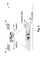
- a system 300 illustrates a projected image in a clear zone in accordance with an aspect of the present invention.
- the system 300 includes a safety camera 310 having associated cameras 320 and projector 330.
- the projector 330 projects an image 340 into a designated zone having a fixed object 350 therein.
- the zone where the projected image 340 is directed is considered a clear zone during initial installation, thus implying that no objects or people normally not in the zone are present.
- the respective cameras 320 capture a picture (pixels) of the image 340. These captured images are illustrated at 360 and 370, respectively.
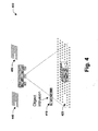
- Fig. 4 illustrates a projected image in an obstructed zone in accordance with an aspect of the present invention.
- an object 410 enters the designated zone and blocks electromagnetic energy from being directed in a projected image at 420.
- the projected image 420 is then captured by detectors of a safety camera 430, the captured images are shown with missing elements (or lowly-illuminated pixels) at 440 and 450, respectively.
- the images 440 and 450 are compared to images taken without the intruding object 410, a determination can be made that an object has entered the zone since, for example, a subtraction of the respective images would indicate that some of the previously illuminated pixels are now darkened ( e.g. , lowered in digital value of intensity) by the intrusion.
- events can be fired that turn off associated machinery or cause other actions to occur.
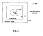
- Fig. 5 illustrates multiple zones and shapes for an area 500 in accordance with an aspect of the present invention.
- the area designated for protection can be sectioned into one or more zones having differing sizes and shapes (e.g. , circular, triangular, rectangular, irregular, cubic, and so forth).
- a warning zone 510 can be configured on an exterior perimeter of the area 500 that if an object is detected therein, a warning or some other indication can be given without actually disabling associated equipment. If an object were to enter a safety zone 520, more direct actions can occur such as actually removing power from respective equipment.
- one or more other zones 530 can be similarly configured having varying degrees of consequences or events associated therewith for objects entering such zones.
- the systems of the present invention are designed for industrial use.
- the task is to detect access of persons to dangerous areas 500 and stop the hazardous movement of a machine in this area.
- a signal is triggered when a person or object enters the monitored area 500 in accordance with the following examples:
- Warning, Safety and or other zones can be achieved through commercially available SCD (Safety Configuration and Diagnostic) Windows-based software. Warning and Safety zones are easily configured through the use of the PCs mouse, for example. Actions such as clicking and dragging points along the perimeter of a desired zone to shape the contour of the zone can be easily achieved.
- SCD Safety Configuration and Diagnostic
- Fig. 6 illustrates an integrated design 600 for a detector and safety instrument in accordance with an aspect of the present invention.
- This aspect illustrates how various components of the safety systems described above can be packaged into a singular housing.
- one or more of the following components may be packaged such as a processor 610 and associated circuits, one or more detectors 620, generally one projector 630, but others can be employed, associated output components 640 that can be triggered by the processor 610 upon detecting an intruding object or person.
- the output components can include various aspects such as output controls for controlling switches, electronic capabilities such as logging events, or other capabilities such as remote network access for notifying people authorized people of an occurrence(s) of an intrusion.
- the system 600 can be designed in a modular manner, whereby one or more of the components 610-640 are adapted and operate remote from the system.
- Fig. 7 illustrates a modular design for a detector and safety system 700 in accordance with an aspect of the present invention.
- one or more of the respective components of the system may be adapted to work as separate components that communicate with one another.
- this type of system may or may not be adapted as a safety system, such systems could also be employed as a security system, wherein an area is monitored for unwanted intruders and warnings and/or alarms are generated upon detected entry of designated areas.
- the system 700 includes a projector 710 that projects into an area 720. Radiation from the area 720 is received by one or more detectors 730 that transmit images over a remote link 740 to a programmable logic controller 750.
- the controller 750 is associated with an output module 760 that controls equipment 770.
- the controller 750 can perform image comparisons and activate or deactivate the equipment 760 via the output module 760.
- the controller could monitor one or more areas 720 via various detectors 730, whereby if intrusions are detected in the respective areas, the controller could log the event, send electronic messages to authorities, sound alarms, and/or send messages to substantially any location via wireless mechanisms or more traditional communication modalities such as over the Internet, for example.
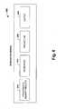
- Fig. 8 illustrates projection angles 800 in accordance with an aspect of the present invention.
- electromagnetic energy can be transmitted to and received from substantially any angle.
- the diagram 800 depicts different relationships such as energy being provided to an area 810 from above the area at 820 and/or below the are at 830.
- energy can be directed from differing sides and at varying depths of an area such as at 840 and 850, for example.
- energy can be received from a plurality of differing angles such as illustrated at 860.
- intrusions can be detected from a plurality of angles and directions.
- Fig. 9 illustrates a detection methodology 900 in accordance with an aspect the present invention. While, for purposes of simplicity of explanation, the methodology is shown and described as a series of acts, it is to be understood and appreciated that the present invention is not limited by the order of acts, as some acts may, in accordance with the present invention, occur in different orders and/or concurrently with other acts from that shown and described herein. For example, those skilled in the art will understand and appreciate that a methodology could alternatively be represented as a series of interrelated states or events, such as in a state diagram. Moreover, not all illustrated acts may be required to implement a methodology in accordance with the present invention.
- a pattern is projected as electromagnetic energy on an area or designated zone.
- the pattern can include substantially any type of pattern and the energy can be in the infrared spectrum or other frequency.
- an initial image is captured of the pattern during a period when it is known that no unintended objects are in the area. This period often correlates to an initial installation of the system.
- images of the designated area are captured at regular intervals (can also occur aperiodically).
- a determination is made as to whether or not an intrusion has occurred. This is achieved by comparing the initial image captured with subsequent images that are captured at 930 and determining whether or not some of the pixels after comparison are at a different intensity than the originally captured pixels.
- the process proceeds to 950 and triggers an event such as energizing/de-energizing an output, sounding an alarm, or generating a notification, for example. If no change is detected at 940, the process proceeds back to 930 and continues to monitor for subsequent intrusions into the designated or defined area. As noted above, three-dimensional reconstructions can be created with multiple detectors to determine intrusions in multiple dimensions of space.
- Fig. 10 illustrates an alternative detection system 1000 for determining contours in a 3D image in accordance with an aspect of the present invention.
- a Distance A at 1010 is shown between a camera A 1020 and a camera B 1030, wherein Distance A is defined as a known parameter or distance.
- An angle a at 1040 under which camera A 1020 receives input from a projection C at 1050 is known as an angle b at 1060 under which camera B 1030 receives input from projection C 1050.
- the angles a 1040 and b 1060 are derived from 2D pictures created by both cameras 1020 and 1030, respectively.
- aspects of the system 1000 include:
- the invention relates to an automated safety system having at least one projector to direct electromagnetic energy into a region of space associated with a security, warning, or safety zone.
- a detector or detectors senses an interruption of the electromagnetic energy in the region of space by an object or person that may enter the space.
- the system includes a processor and a storage component, wherein the processor determines the interruption by comparing a current image from the detector with a previously stored image in the storage component. Upon detection, the processor triggers an event based upon the comparison, whereby the event includes such aspects as activating an output, de-energizing a machine, sounding a warning, sounding an alarm, storing data associated with the event, and sending a notification to a local or a remote system, for example.
Landscapes
- Engineering & Computer Science (AREA)
- General Engineering & Computer Science (AREA)
- Multimedia (AREA)
- Signal Processing (AREA)
- Mechanical Engineering (AREA)
- Burglar Alarm Systems (AREA)
- Alarm Systems (AREA)
- Emergency Alarm Devices (AREA)
- Geophysics And Detection Of Objects (AREA)
Claims (30)
- Automatisches Sicherheitssystem, das Folgendes umfasst:wenigstens einen Projektor (330), um elektromagnetische Energie in einen Raumbereich zum Bilden eines projizierten Bildes (340) zu projizieren;wenigstens eine erste und eine zweite Kamera (310, 320), die in einem vorgegebenen Abstand in Bezug aufeinander angeordnet sind, wobei die Kameras in einem bekannten Winkel bezüglich des Projektors (330) angeordnet sind, um einen dreidimensionalen Umriss eines Objektes zu bestimmen,
wobei die erste Kamera (310) betreibbar ist, ein erstes gespeichertes Bild (360) wenigstens eines Teils des Raumbereiches und wenigstens ein erstes momentanes Bild (440) des Teils aufzuzeichnen; und
wobei die zweite Kamera (320) betreibbar ist, ein zweites gespeichertes Bild (370) wenigstens eines Teils des Raumbereiches aus einem abweichenden Winkel bezüglich des Projektors und wenigstens ein zweites momentanes Bild (450) des Teils des Raumbereichs aus dem abweichenden Winkel aufzuzeichnen;einen Prozessor (160, 610), der betreibbar ist, eine Unterbrechung der elektromagnetischen Energie in dem Raumbereich durch das Analysieren einer Bildpunktintensität des ersten und des zweiten momentanen Bildes (440, 450) im Vergleich zu dem ersten und dem zweiten gespeicherten Bild (360, 370) abzutasten, wobei der Prozessor ferner betreibbar ist,
eine Unterbrechung durch das Vergleichen eines Unterschieds der analysierten Bildpunktintensität zwischen dem ersten gespeicherten Bild und dem ersten momentanen Bild sowie dem zweiten gespeicherten Bild und dem zweiten momentanen Bild zu detektieren. - System nach Anspruch 1, wobei der Prozessor (160, 610) basierend auf dem Vergleich ein Ereignis auslöst.
- System nach Anspruch 2, wobei das Ereignis die Aktivierung einer Ausgabe, das Anhalten der Energiezufuhr zu einer Maschine, das Ertönen einer Warnung, das Ertönen eines Alarms, das Speichern der dem Ereignis zugeordneten Daten und das Senden einer Meldung an ein lokales oder entferntes System enthält.
- System nach einem der vorhergehenden Ansprüche, wobei der Prozessor (160, 610) ein zweidimensionales Bild und/oder ein dreidimensionales Bild von dem Detektor nach Anspruch 1 konstruiert, um die Unterbrechung zu bestimmen.
- System nach einem der vorhergehenden Ansprüche, wobei die elektromagnetische Energie Infrarotstrahlung umfasst, die eine Wellenlänge von etwa 840 Nanometer (nm) bis etwa 950 nm besitzt.
- System nach einem der vorhergehenden Ansprüche, wobei der Raumbereich als eine Schutzzone zugeteilt ist, die null oder mehr Objekte enthält, die normalerweise den Bereich einnehmen.
- System nach einem der vorhergehenden Ansprüche, wobei der Detektor den Raumbereich in vorgegebenen oder unregelmäßigen Intervallen nach Eindringereignissen überwacht.
- System nach einem der vorhergehenden Ansprüche, wobei die Unterbrechung aus einem Schwellenwert, der mit der Bildpunktintensität in Beziehung steht, bestimmt wird.
- System nach einem der vorhergehenden Ansprüche, das ferner wenigstens einen Sicherheitsausgang und ein Sicherheitsrelais zum Steuern von Geräten umfasst.
- System nach einem der vorhergehenden Ansprüche, wobei der Projektor ein Muster für die Infrarotstrahlung in den Raumbereich lenkt.
- System nach einem der vorhergehenden Ansprüche, wobei der Projektor mit einer Zoom-Linse mit Einstellungen zum Einstellen des Brennpunkts ausgerüstet ist.
- System nach einem der vorhergehenden Ansprüche, das ferner Software zum Einstellen einer oder mehrerer Zonen, die ähnliche oder unterschiedliche Formen besitzen, umfasst.
- System nach Anspruch 12, wobei die Zonen als eine Warnzone, eine Sicherheitszone und eine Schutzzone konfiguriert sind.
- System nach einem der vorhergehenden Ansprüche, das ferner eine Steuerkomponente umfasst, die einen oder mehrere Bereiche über verschiedene Detektoren überwacht und/oder Ereignisse protokolliert und/oder elektronische Nachrichten an Behörden sendet und/oder Alarme ertönen lässt und/oder Nachrichten im Wesentlichen drahtlos sendet und/oder über das Internet kommuniziert.
- Automatisches Sicherheitssystem nach Anspruch 1, wobei der Prozessor ferner betreibbar ist, um teilweise auf dem Bestimmen einer Unterbrechung der elektromagnetischen Energie von den Kameras basierend einen Sicherheitsausgang zu aktivieren, um eine Maschinerie zu steuern.
- System nach Anspruch 15, das ferner eine Komponente für eine Winkelmessung umfasst, die einen Unterschied der Winkel bestimmt, wo eine ähnliche Projektion durch Detektoren detektiert wird.
- System nach Anspruch 15 oder 16, das ferner eine Erkennungszone umfasst, die in den Detektoren programmiert ist, um einen Umriss eines Objektes zu bestimmen.
- System nach Anspruch 17, das ferner eine Komponente zum Bestimmen umfasst, ob der Umriss den vorprogrammierten Anforderungen entspricht, wobei dann dem Objekt erlaubt wird, in eine Sicherheitszone einzudringen, ohne die zugeordneten Ausgänge zu veranlassen, den Zustand zu ändern.
- System nach einem der Ansprüche 15 bis 18, wobei die Detektoren einen oder mehrere Eingänge enthalten, um eine anschließende Funktionalität zu aktivieren.
- System nach einem der Ansprüche 15 bis 19, wobei die Detektoren mit einem Konfigurationsmodul ausgerüstet sind, das die programmierten Konfigurationen für die Leichtigkeit des Austauschs mit anderen Detektoren speichert.
- System nach einem der Ansprüche 15 bis 20, wobei der Projektor mit 1 oder mehr Bezugsprojektionen als eine Basis, um die Detektoren als einen Teil der Gesamtanordnung zu synchronisieren, um Winkelmessungen zu ermöglichen, ausgerüstet ist.
- System nach einem der Ansprüche 15 bis 21, wobei das Objekt mit einem Hilfsprojektor ausgerüstet ist, der durch die Detektoren detektierbare Energie emittiert und verwendet wird, um die Bewegung des Objekts zu verfolgen, um eine oder mehr Funktionen in den Detektoren zu aktivieren.
- System nach Anspruch 22, wobei die Funktionen das Auslösen des Detektors, um die vorprogrammierten Zonen in eine weitere vorprogrammierte Zone zu ändern, oder das Freigeben des Detektors, mit "aktiven" Zonen zu arbeiten, einschließlich der Zonen, die sich an einen tatsächlichen Zustand der die durch den Detektor geschützten Maschinerie anpassen, enthalten.
- System nach einem der Ansprüche 15 bis 23, wobei die Detektoren mit einem oder mehreren E/A-Anschlüssen ausgerüstet sind, um eine oder mehrere Detektoranordnungen miteinander zu verbinden, die eine Funktionskette bilden.
- Verfahren zum Schaffen automatisierten Schutzes für einen Bereich, das Folgendes umfasst:Projizieren eines elektromagnetischen Energiemusters in einen definierten Bereich;Aufnehmen von Bildern des elektromagnetischen Energiemusters und des definierten Bereichs, wobei
eine erste Infrarotkamera (310) ein erstes gespeichertes Bild (360) wenigstens eines Teils des Raumbereiches und wenigstens ein erstes momentanes Bild (440) des Teils aufzeichnet; und
eine zweite Infrarotkamera (320) ein zweites gespeichertes Bild (370) wenigstens eines Teils des Raumbereiches aus einem abweichenden Winkel und wenigstens ein zweites momentanes Bild (450) des Teils des Raumbereichs aus dem abweichenden Winkel aufzeichnet;automatisches Bestimmen, ob ein Eindringen in den definierten Bereich stattgefunden hat, durch das Detektieren eines Schattens in dem elektromagnetischen Energiemuster,wobei ein Prozessor (160, 610) eine Unterbrechung der elektromagnetischen Energie in dem Raumbereich durch das Analysieren einer Bildpunktintensität des ersten und des zweiten momentanen Bildes (440, 450) im Vergleich zu dem ersten und dem zweiten gespeicherten Bild (360, 370) abtastet, undder Prozessor ferner eine Unterbrechung durch das Vergleichen eines Unterschieds der analysierten Bildpunktintensität zwischen dem ersten gespeicherten Bild und dem ersten momentanen Bild sowie dem zweiten gespeicherten Bild und zweiten momentanen Bild abtastet. - Verfahren nach Anspruch 25, das ferner das Überwachen des definierten Bereichs in vorgegebenen Intervallen umfasst.
- Verfahren nach Anspruch 26, das ferner das automatische Überwachen des definierten Bereichs aus der Ferne über ein Steuersystem umfasst.
- Verfahren nach einem der Ansprüche 25 bis 27, das ferner das Vergleichen eines Anfangsbildes mit anschließend aufgenommenen Bildern und das Bestimmen, ob ein oder mehrere zugeordnete Bildpunkte nach dem Vergleich eine andere Intensität als die anfangs aufgenommenen Bildpunkte besitzen, umfasst.
- Verfahren nach einem der Ansprüche 25 bis 28, das ferner das Auslösen eines Ereignisses und/oder die Zufuhr von Energie oder das Anhalten der Zufuhr von Energie zu einem Ausgang und/oder das Ertönen eines Alarms und/oder das Erzeugen einer Meldung umfasst.
- Verfahren nach einem der Ansprüche 25 bis 29, wobei die elektromagnetische Energie Infrarotstrahlung umfasst, die eine Wellenlänge von etwa 840 Nanometer (nm) bis etwa 950 nm besitzt.
Applications Claiming Priority (2)
| Application Number | Priority Date | Filing Date | Title |
|---|---|---|---|
| US10/851,600 US7440620B1 (en) | 2004-05-21 | 2004-05-21 | Infrared safety systems and methods |
| US851600 | 2004-05-21 |
Publications (2)
| Publication Number | Publication Date |
|---|---|
| EP1598792A1 EP1598792A1 (de) | 2005-11-23 |
| EP1598792B1 true EP1598792B1 (de) | 2012-12-26 |
Family
ID=34936661
Family Applications (1)
| Application Number | Title | Priority Date | Filing Date |
|---|---|---|---|
| EP05010799A Ceased EP1598792B1 (de) | 2004-05-21 | 2005-05-18 | Sicherheitssystem und -methode mit Infrarotstrahlen |
Country Status (4)
| Country | Link |
|---|---|
| US (1) | US7440620B1 (de) |
| EP (1) | EP1598792B1 (de) |
| JP (1) | JP2005339543A (de) |
| CN (1) | CN1755741A (de) |
Cited By (1)
| Publication number | Priority date | Publication date | Assignee | Title |
|---|---|---|---|---|
| CN107298216A (zh) * | 2016-04-15 | 2017-10-27 | 里特机械公司 | 用于操作拆包机的方法和这种拆包机 |
Families Citing this family (51)
| Publication number | Priority date | Publication date | Assignee | Title |
|---|---|---|---|---|
| JP2005324297A (ja) * | 2004-05-17 | 2005-11-24 | Matsushita Electric Ind Co Ltd | ロボット |
| KR100630842B1 (ko) * | 2005-06-08 | 2006-10-02 | 주식회사 현대오토넷 | 스테레오 영상 정합을 이용한 자동차의 탑승자 자세 판별시스템 및 그 방법 |
| US8081304B2 (en) | 2006-07-31 | 2011-12-20 | Visualant, Inc. | Method, apparatus, and article to facilitate evaluation of objects using electromagnetic energy |
| DE102007039565A1 (de) * | 2006-09-04 | 2008-04-10 | Robert Bosch Gmbh | Werkzeugmaschinenüberwachungsvorrichtung |
| DE102007041098A1 (de) * | 2006-09-04 | 2008-03-06 | Robert Bosch Gmbh | Werkzeugmaschinenüberwachungsvorrichtung |
| EP2115716A1 (de) * | 2006-12-11 | 2009-11-11 | Conseng Pty Ltd | Überwachungssystem |
| DE102007036129B3 (de) * | 2007-08-01 | 2008-09-25 | Sick Ag | Vorrichtung und Verfahren zur dreidimensionalen Überwachung eines Raumbereichs mit mindestens zwei Bildsensoren |
| DE102007044804A1 (de) * | 2007-09-20 | 2009-04-09 | Robert Bosch Gmbh | Werkzeugmaschinensicherheitsvorrichtung |
| DE102007045528A1 (de) * | 2007-09-24 | 2009-04-23 | Siemens Ag | Medizinisches Diagnose- und/oder Therapiesystem und Verfahren zur Visualisierung von Überwachungsbereichen bei einem Medizinischen Diagnose- und/oder Therapiesystem |
| DE102007062996A1 (de) * | 2007-12-21 | 2009-06-25 | Robert Bosch Gmbh | Werkzeugmaschinenvorrichtung |
| CA2721616A1 (en) * | 2008-04-17 | 2009-12-03 | Shilat Optronics Ltd | Intrusion warning system |
| US8639527B2 (en) | 2008-04-30 | 2014-01-28 | Ecolab Usa Inc. | Validated healthcare cleaning and sanitizing practices |
| EP2294544A4 (de) | 2008-04-30 | 2013-01-16 | Ecolab Inc | Validierte gesundheitsversorgungs-reinigungs- und desinfektionspraktiken |
| US20100066983A1 (en) * | 2008-06-17 | 2010-03-18 | Jun Edward K Y | Methods and systems related to a projection surface |
| WO2010002237A2 (en) * | 2008-06-30 | 2010-01-07 | Mimos Berhad | Intrusion detection using parallax information |
| USRE48951E1 (en) | 2015-08-05 | 2022-03-01 | Ecolab Usa Inc. | Hand hygiene compliance monitoring |
| PL2441063T3 (pl) | 2009-06-12 | 2015-08-31 | Ecolab Usa Inc | Monitorowanie przestrzegania higieny rąk |
| DE102009031732B3 (de) * | 2009-07-04 | 2010-11-25 | Sick Ag | Entfernungsmessender optoelektronischer Sensor |
| CN101794064B (zh) * | 2009-12-21 | 2012-01-11 | 深圳雅图数字视频技术有限公司 | 投影显像装置及其控制方法 |
| US8427324B2 (en) | 2010-07-30 | 2013-04-23 | General Electric Company | Method and system for detecting a fallen person using a range imaging device |
| US20120106778A1 (en) * | 2010-10-28 | 2012-05-03 | General Electric Company | System and method for monitoring location of persons and objects |
| US20140210620A1 (en) | 2013-01-25 | 2014-07-31 | Ultraclenz Llc | Wireless communication for dispenser beacons |
| US8421624B2 (en) * | 2011-05-09 | 2013-04-16 | Tau-Jeng Hsu | Home security system |
| CN102542715A (zh) * | 2011-12-21 | 2012-07-04 | 西安石油大学 | 一种基于光编码技术的人员入侵智能报警装置 |
| US8888207B2 (en) | 2012-02-10 | 2014-11-18 | Visualant, Inc. | Systems, methods and articles related to machine-readable indicia and symbols |
| WO2013119822A1 (en) * | 2012-02-10 | 2013-08-15 | Visualant, Inc. | Area surveillance systems and methods |
| US20140063239A1 (en) * | 2012-02-10 | 2014-03-06 | Visualant, Inc. | Area surveillance systems and methods |
| US9316581B2 (en) | 2013-02-04 | 2016-04-19 | Visualant, Inc. | Method, apparatus, and article to facilitate evaluation of substances using electromagnetic energy |
| US9041920B2 (en) | 2013-02-21 | 2015-05-26 | Visualant, Inc. | Device for evaluation of fluids using electromagnetic energy |
| US9664610B2 (en) | 2013-03-12 | 2017-05-30 | Visualant, Inc. | Systems for fluid analysis using electromagnetic energy that is reflected a number of times through a fluid contained within a reflective chamber |
| US10330258B2 (en) * | 2013-12-24 | 2019-06-25 | Robert Bosch Tool Corporation | Power tool with ultrasonic sensor for sensing contact between an implement and an object |
| US9256944B2 (en) * | 2014-05-19 | 2016-02-09 | Rockwell Automation Technologies, Inc. | Integration of optical area monitoring with industrial machine control |
| NL2013480B1 (en) * | 2014-09-17 | 2016-09-28 | Van Ginderen License & Finance B V | A method guarding an object or area, a guarding unit and a computer program product. |
| US9435635B1 (en) * | 2015-02-27 | 2016-09-06 | Ge Aviation Systems Llc | System and methods of detecting an intruding object in a relative navigation system |
| US10043288B2 (en) | 2015-11-10 | 2018-08-07 | Honeywell International Inc. | Methods for monitoring combustion process equipment |
| DE102015224309A1 (de) * | 2015-12-04 | 2017-06-08 | Kuka Roboter Gmbh | Darstellung variabler Schutzfelder |
| CN105785706A (zh) * | 2016-05-20 | 2016-07-20 | 中山市厚源电子科技有限公司 | 一种应用幻影成像膜的裸眼3d成像装置 |
| DE102016118758B4 (de) * | 2016-10-04 | 2025-10-09 | Sick Ag | Optoelektronischer Sensor und Verfahren zur optischen Erfassung eines Überwachungsbereichs |
| BR112019018376B1 (pt) | 2017-03-07 | 2024-02-20 | Ecolab Usa Inc | Dispositivo, e, módulo de sinalização de dispensador |
| JP6416980B1 (ja) | 2017-05-17 | 2018-10-31 | ファナック株式会社 | 監視領域を分割した空間領域を監視する監視装置 |
| US10619107B2 (en) | 2017-06-22 | 2020-04-14 | Honeywell International Inc. | Heater coil |
| WO2019005916A1 (en) * | 2017-06-28 | 2019-01-03 | Schneider Electric It Corporation | SYSTEMS AND METHODS FOR INTRUSION DETECTION FOR BAY SPEAKERS |
| US10529219B2 (en) | 2017-11-10 | 2020-01-07 | Ecolab Usa Inc. | Hand hygiene compliance monitoring |
| US10650646B2 (en) * | 2017-12-06 | 2020-05-12 | Illinois Tool Works Inc. | Method of increasing detection zone of a shadow-based video intrusion detection system |
| EP3629141B1 (de) * | 2018-09-28 | 2021-04-14 | Sick Ag | Verfahren und vorrichtung zum überprüfen eines konfigurationsparameterwerts |
| JP7435988B2 (ja) | 2018-12-17 | 2024-02-21 | 日本電気通信システム株式会社 | 領域提示システム、領域提示方法及びプログラム |
| WO2020132525A1 (en) | 2018-12-20 | 2020-06-25 | Ecolab Usa Inc. | Adaptive route, bi-directional network communication |
| US11927488B2 (en) | 2019-01-03 | 2024-03-12 | Chia-Ling Chen | Thermal detection system capable of providing early warning and related products |
| IT201900021108A1 (it) * | 2019-11-13 | 2021-05-13 | Gamma System S R L | Sistema di sicurezza per un macchinario industriale |
| US11823559B2 (en) | 2019-12-16 | 2023-11-21 | Motorola Solutions, Inc. | Method and system to project guidance to building occupants during an emergency situation |
| US12128852B2 (en) * | 2022-04-20 | 2024-10-29 | Caterpillar Sarl | System and method for maintaining a power source for continuous machine security monitoring |
Family Cites Families (19)
| Publication number | Priority date | Publication date | Assignee | Title |
|---|---|---|---|---|
| US4196425A (en) * | 1978-07-10 | 1980-04-01 | by said David S. Weekly said Clyde E. Williams | Patient activity monitoring system |
| JPS59193382A (ja) * | 1983-04-18 | 1984-11-01 | Sogo Keibi Hoshiyou Kk | 侵入検知装置 |
| IL86202A (en) * | 1988-04-27 | 1992-01-15 | Driver Safety Systems Ltd | Traffic safety monitoring apparatus |
| JPH02182093A (ja) * | 1989-01-07 | 1990-07-16 | Mitsubishi Electric Corp | 監視装置 |
| US5164707A (en) * | 1990-02-28 | 1992-11-17 | Cabot Safety Corporation | Detection system for safety equipment |
| JPH0431996A (ja) * | 1990-05-28 | 1992-02-04 | Matsushita Electric Works Ltd | 画像認識型の防犯センサー |
| EP0466522B1 (de) * | 1990-07-11 | 1997-11-26 | Optex Co. Ltd. | Infrarot-Eindringalarmanlage |
| US5406073A (en) * | 1993-01-25 | 1995-04-11 | Phoenix Controls Corporation | System for detecting a movable entity within a selected space |
| US5446548A (en) * | 1993-10-08 | 1995-08-29 | Siemens Medical Systems, Inc. | Patient positioning and monitoring system |
| JP2000036084A (ja) * | 1998-07-16 | 2000-02-02 | Hyper Electronics:Kk | 進入物監視装置 |
| US6370260B1 (en) * | 1999-09-03 | 2002-04-09 | Honeywell International Inc. | Near-IR human detector |
| US6297844B1 (en) * | 1999-11-24 | 2001-10-02 | Cognex Corporation | Video safety curtain |
| GB2366862B (en) | 2000-09-14 | 2004-09-22 | Autoliv Dev | Improvements in or relating to a camera arrangement |
| US6720874B2 (en) * | 2000-09-29 | 2004-04-13 | Ids Systems, Inc. | Portal intrusion detection apparatus and method |
| US6841780B2 (en) * | 2001-01-19 | 2005-01-11 | Honeywell International Inc. | Method and apparatus for detecting objects |
| JP2003099861A (ja) * | 2001-09-26 | 2003-04-04 | Kumahira Safe Co Inc | 人体検知装置及び入退室管理システム |
| JP2003187342A (ja) * | 2001-12-19 | 2003-07-04 | Hitachi Ltd | セキュリティシステム |
| US6806811B1 (en) * | 2002-03-27 | 2004-10-19 | Blaine C. Readler | Infra-red perimeter alarm |
| GB2396004B (en) * | 2002-12-06 | 2006-02-22 | Optex Co Ltd | Anti-thief security sensor assembly with variable amount of emitted infrared beam |
-
2004
- 2004-05-21 US US10/851,600 patent/US7440620B1/en active Active
-
2005
- 2005-05-18 EP EP05010799A patent/EP1598792B1/de not_active Ceased
- 2005-05-20 CN CNA2005100837873A patent/CN1755741A/zh active Pending
- 2005-05-20 JP JP2005147581A patent/JP2005339543A/ja active Pending
Cited By (2)
| Publication number | Priority date | Publication date | Assignee | Title |
|---|---|---|---|---|
| CN107298216A (zh) * | 2016-04-15 | 2017-10-27 | 里特机械公司 | 用于操作拆包机的方法和这种拆包机 |
| CN107298216B (zh) * | 2016-04-15 | 2022-06-24 | 里特机械公司 | 用于操作拆包机的方法和这种拆包机 |
Also Published As
| Publication number | Publication date |
|---|---|
| US7440620B1 (en) | 2008-10-21 |
| US20080240577A1 (en) | 2008-10-02 |
| EP1598792A1 (de) | 2005-11-23 |
| JP2005339543A (ja) | 2005-12-08 |
| CN1755741A (zh) | 2006-04-05 |
Similar Documents
| Publication | Publication Date | Title |
|---|---|---|
| EP1598792B1 (de) | Sicherheitssystem und -methode mit Infrarotstrahlen | |
| JP6449263B2 (ja) | 自動的に作動する機械を保護する装置および方法 | |
| US7167575B1 (en) | Video safety detector with projected pattern | |
| KR102786033B1 (ko) | 모니터링 장치, 산업 설비, 모니터링 방법, 및 컴퓨터 프로그램 | |
| US9596451B2 (en) | Device for monitoring at least one three-dimensional safety area | |
| US7924164B1 (en) | Method for sensing the presence of a human body part within a region of a machine tool | |
| CN109477608B (zh) | 用于切割机的增强安全附件 | |
| JP4405468B2 (ja) | 危険領域を保護する方法および装置 | |
| US6469734B1 (en) | Video safety detector with shadow elimination | |
| US10726538B2 (en) | Method of securing a hazard zone | |
| JP6491640B2 (ja) | 自動的に作動する機械を保護するための装置および方法ならびにコンピュータ・プログラムデータ記憶媒体 | |
| US10969762B2 (en) | Configuring a hazard zone monitored by a 3D sensor | |
| JP2003222295A (ja) | 機械の保安関連機能を制御する方法及び装置 | |
| EP1249135A4 (de) | Video-sicherheitsvorhang | |
| CN113739058B (zh) | 用于防护机器的光电安全传感器和方法 | |
| JP5027273B2 (ja) | 物体検出センサおよび警備システム | |
| US12290939B2 (en) | Sensor arrangement and method for safeguarding a monitored zone | |
| JPH08160127A (ja) | 移動体からの対象近接検出方法 | |
| JP2003121556A (ja) | 物体検出装置及びその方法 | |
| JP4481432B2 (ja) | 画像式監視方法、並びに、画像式監視装置およびそれを用いた安全システム | |
| WO2007020666A1 (en) | Vision sensor for security systems and its operating method | |
| JP7793398B2 (ja) | 物体検出装置および物体検出システム | |
| US20220196844A1 (en) | System and Method For Preventing Collision | |
| US20250073932A1 (en) | Contactless safeguarding at a cooperation zone of a machine | |
| Kerezović et al. | Human safety in robot applications–review of safety trends |
Legal Events
| Date | Code | Title | Description |
|---|---|---|---|
| PUAI | Public reference made under article 153(3) epc to a published international application that has entered the european phase |
Free format text: ORIGINAL CODE: 0009012 |
|
| AK | Designated contracting states |
Kind code of ref document: A1 Designated state(s): AT BE BG CH CY CZ DE DK EE ES FI FR GB GR HU IE IS IT LI LT LU MC NL PL PT RO SE SI SK TR |
|
| AX | Request for extension of the european patent |
Extension state: AL BA HR LV MK YU |
|
| 17P | Request for examination filed |
Effective date: 20060420 |
|
| AKX | Designation fees paid |
Designated state(s): DE FR GB IT |
|
| GRAP | Despatch of communication of intention to grant a patent |
Free format text: ORIGINAL CODE: EPIDOSNIGR1 |
|
| GRAS | Grant fee paid |
Free format text: ORIGINAL CODE: EPIDOSNIGR3 |
|
| GRAA | (expected) grant |
Free format text: ORIGINAL CODE: 0009210 |
|
| AK | Designated contracting states |
Kind code of ref document: B1 Designated state(s): DE FR GB IT |
|
| REG | Reference to a national code |
Ref country code: GB Ref legal event code: FG4D |
|
| REG | Reference to a national code |
Ref country code: DE Ref legal event code: R096 Ref document number: 602005037559 Country of ref document: DE Effective date: 20130228 |
|
| PLBE | No opposition filed within time limit |
Free format text: ORIGINAL CODE: 0009261 |
|
| STAA | Information on the status of an ep patent application or granted ep patent |
Free format text: STATUS: NO OPPOSITION FILED WITHIN TIME LIMIT |
|
| 26N | No opposition filed |
Effective date: 20130927 |
|
| PG25 | Lapsed in a contracting state [announced via postgrant information from national office to epo] |
Ref country code: IT Free format text: LAPSE BECAUSE OF FAILURE TO SUBMIT A TRANSLATION OF THE DESCRIPTION OR TO PAY THE FEE WITHIN THE PRESCRIBED TIME-LIMIT Effective date: 20121226 |
|
| REG | Reference to a national code |
Ref country code: DE Ref legal event code: R097 Ref document number: 602005037559 Country of ref document: DE Effective date: 20130927 |
|
| REG | Reference to a national code |
Ref country code: FR Ref legal event code: PLFP Year of fee payment: 12 |
|
| REG | Reference to a national code |
Ref country code: FR Ref legal event code: PLFP Year of fee payment: 13 |
|
| REG | Reference to a national code |
Ref country code: FR Ref legal event code: PLFP Year of fee payment: 14 |
|
| P01 | Opt-out of the competence of the unified patent court (upc) registered |
Effective date: 20230404 |
|
| PGFP | Annual fee paid to national office [announced via postgrant information from national office to epo] |
Ref country code: FR Payment date: 20230420 Year of fee payment: 19 Ref country code: DE Payment date: 20230419 Year of fee payment: 19 |
|
| PGFP | Annual fee paid to national office [announced via postgrant information from national office to epo] |
Ref country code: GB Payment date: 20230420 Year of fee payment: 19 |
|
| REG | Reference to a national code |
Ref country code: DE Ref legal event code: R119 Ref document number: 602005037559 Country of ref document: DE |
|
| GBPC | Gb: european patent ceased through non-payment of renewal fee |
Effective date: 20240518 |
|
| PG25 | Lapsed in a contracting state [announced via postgrant information from national office to epo] |
Ref country code: DE Free format text: LAPSE BECAUSE OF NON-PAYMENT OF DUE FEES Effective date: 20241203 |
|
| PG25 | Lapsed in a contracting state [announced via postgrant information from national office to epo] |
Ref country code: FR Free format text: LAPSE BECAUSE OF NON-PAYMENT OF DUE FEES Effective date: 20240531 |
|
| PG25 | Lapsed in a contracting state [announced via postgrant information from national office to epo] |
Ref country code: GB Free format text: LAPSE BECAUSE OF NON-PAYMENT OF DUE FEES Effective date: 20240518 |