EP1598643A2 - Circuit de correction d'erreur d'un codeur - Google Patents
Circuit de correction d'erreur d'un codeur Download PDFInfo
- Publication number
- EP1598643A2 EP1598643A2 EP05104080A EP05104080A EP1598643A2 EP 1598643 A2 EP1598643 A2 EP 1598643A2 EP 05104080 A EP05104080 A EP 05104080A EP 05104080 A EP05104080 A EP 05104080A EP 1598643 A2 EP1598643 A2 EP 1598643A2
- Authority
- EP
- European Patent Office
- Prior art keywords
- encoder
- codewheel
- correction circuit
- output
- signal
- Prior art date
- Legal status (The legal status is an assumption and is not a legal conclusion. Google has not performed a legal analysis and makes no representation as to the accuracy of the status listed.)
- Granted
Links
Images

Classifications
-
- G—PHYSICS
- G01—MEASURING; TESTING
- G01D—MEASURING NOT SPECIALLY ADAPTED FOR A SPECIFIC VARIABLE; ARRANGEMENTS FOR MEASURING TWO OR MORE VARIABLES NOT COVERED IN A SINGLE OTHER SUBCLASS; TARIFF METERING APPARATUS; MEASURING OR TESTING NOT OTHERWISE PROVIDED FOR
- G01D5/00—Mechanical means for transferring the output of a sensing member; Means for converting the output of a sensing member to another variable where the form or nature of the sensing member does not constrain the means for converting; Transducers not specially adapted for a specific variable
- G01D5/12—Mechanical means for transferring the output of a sensing member; Means for converting the output of a sensing member to another variable where the form or nature of the sensing member does not constrain the means for converting; Transducers not specially adapted for a specific variable using electric or magnetic means
- G01D5/244—Mechanical means for transferring the output of a sensing member; Means for converting the output of a sensing member to another variable where the form or nature of the sensing member does not constrain the means for converting; Transducers not specially adapted for a specific variable using electric or magnetic means influencing characteristics of pulses or pulse trains; generating pulses or pulse trains
- G01D5/24471—Error correction
- G01D5/24476—Signal processing
Definitions
- the present invention generally relates to image reproduction devices or image forming apparatuses, such as high speed printers. More specifically, the present invention relates to improving the precision of aligning printing elements such as paper and rotating print drums in a system using low-cost encoder sensors.
- the general solution and improvement proffered by the Markham patent is to use two low-cost encoders mounted 180 degrees apart to cut the effective encoder runout error in half by averaging the periods of the two codewheel encoders. While this approach improves over single encoder approaches, some limitations still remain.
- the Markham patent approach suffers the possibility of glitches and discontinuities that occur in the correction signal when the rising edges of the output signals from both of the encoders cross each other. Such discontinuities are known to lead to defects in the print system images.
- Averaging techniques to correct runout error may also be implemented using microcontrollers.
- the present invention presents an advantage over this approach because microcontrollers are often too slow for the amount and speed of processing required in high-speed printers. Many microcontrollers do not have sufficient timer resolution and are largely consumed performing this one task. Since most systems already contain an FPGA or ASIC, the present invention represents a significant cost savings, as it can be implemented in the FPGA or ASIC and will consume a very small amount of its resources.
- the present invention provides an encoder system adapted for use in print architecture that at least includes: a codewheel coupled to a rotating print architecture element; a first encoder sensor mounted at a first position relative to the periphery of the codewheel, the first encoder adapted to output a first output signal; a second sensor mounted at a second position relative to the periphery of the codewheel, the second encoder adapted to output a second output signal, and the second sensor positioned substantially 180 degrees relative to the first encoder sensor; and a logic correction circuit adapted to receive the first and second output signals, and for outputting a correction signal with a period that is the average of the periods of the first and second output signals.
- the present invention also provides an encoder signal processing method adapted for use in print architecture at least including: coupling a codewheel to a rotating print architecture element; mounting a first encoder sensor at a first position relative to the periphery of the codewheel; via the first encoder, outputting a first output signal; mounting a second sensor at a second position relative to the periphery of the codewheel, the second sensor positioned substantially 180 degrees relative to the first encoder sensor; via the second encoder, outputting a second output signal; and receiving the first and second output signals, and outputting a correction signal with a period that is the average of the periods of the first and second output signals.
- said rotating print architecture element comprises an imaging drum, further comprising:
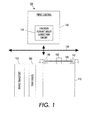
- Figure 1 is a schematic diagram of a portion of the printing architecture associated with the present-inventive encoder runout error correction scheme, including the imaging drum, the codewheel, encoders and the print control module;
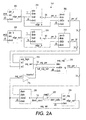
- Figure 2A is a schematic diagram of a first portion of the present-inventive encoder runout error correction circuit
- Figure 2B is a schematic diagram of a second portion of the present-inventive encoder runout error correction circuit.
- printer refers, for example, to reproduction devices in general, such as printers, facsimile machines, and copiers.
- a rotating imaging drum 110 has a codewheel 120 mounted on its side via a mount 130.
- Two encoders 140 and 142 are mounted to the printing architecture 180 degrees apart in position to sense the position and movement of the codewheel.
- the movement of the imaging drum is carefully synchronized with the operation of a paper transport mechanism 170 and a number of printheads 180, as will be appreciated by those skilled in the art to which the present invention pertains.
- the description heretofore is similar to the aforementioned (and incorporated by reference) Markham patent.
- the overall operation of the print system 100 is controlled by a print control module 160.
- a logic circuit 164 implements the encoder runout error correction function to average the runout error of the two encoders 140 and 142.
- the components of the printing system 100 communicate and receive control signals via a bus 150.
- the encoder runout error correction circuit 164 is implemented via a field programmable gate array (FPGA) in the preferred embodiment.
- FPGA field programmable gate array
- Other possible logic circuit implementations include, inter alia, an application specific integrated circuit (ASIC) or CPLD.
- the encoder runout error correction circuit 164 may be thought of as a state machine for simplicity.
- the components of the circuit 164 are appropriately synchronized to clock pulses from a master clock (not shown).
- two edge detectors 202 and 208 receive output signals (enca and encb) from the encoders 140 and 142, respectively.
- the edge detectors 202 and 208 detect the rising edges of the encoder output signals and output edge out signals one clock cycle long.
- the edge out signals are presented to two 14-bit up counters 204 and 210 to load the counters with the value "1.” After the counters 204 and 210 are loaded, they begin counting up at the clock rate of 20 megahertz until they are once again cleared by the next rising edges of the encoder output signals. The number of clock cycles between rising edges represents the period of the encoder output signals.
- the rising edge signals also activate period registers 206 and 212, which latch the period of the encoder output signals.
- the periods of the two encoder output signals are fed to a combinatorial logic element 214 that averages the two periods by adding the two periods, and then dividing the sum by two.
- the average period (“avg_per”) output signal from the combinatorial logic element 214 is fed to an average period register 218, which is used to synchronize the average period signal to the clock signal.
- the synchronized average period signal (“avg_per_r”) is introduced to a down counter 220, which times the period of the corrected signal ("enc_out").
- a combinatorial logic element 222 causes an "output register" 224 to output the average period signal.
- Element 224 is really an edge detector which outputs a one cycle pulse ("avg_out") having a period which is the average of the enca and encb signals.
- a feedback path supplies the avg_out signal to an input of the down counter, and to an inverter 216.
- the inverter and the resulting inverted avg_out signal (“not_avg_out”) are used to avoid possible race states. Otherwise the value stored in the down counter 220 might be corrupted when the signal avg_per_r is change while the "aload" input is in transition to a logic low condition.
- An index pulse generation circuit 234 generates an index pulse once per each revolution of the codewheel at the same position each time. Leading up to generating the index pulse, the circuit 234 counts each line of the encoder wheel until the predetermined total of lines on the codewheel is reached.
- a down counter (“pl timer”) 230 uses the avg_out signal from the register 224, which is fed to an input labeled "aset,” and the clock pulse to generate a pulse length timer signal, the most significant bit of which is buffered by element 232 to form the corrected output signal ("enc_out”).
- the avg_out signal sets the "pl timer” 230 and raise 10 bits of the pulse_length_timer signal to change to a logic high condition.
- the counter 230 counts down to zero, it is disabled and the corrected output signal enc_out is cleared until a new avg_out signal is received.
Landscapes
- Engineering & Computer Science (AREA)
- Signal Processing (AREA)
- Physics & Mathematics (AREA)
- General Physics & Mathematics (AREA)
- Transmission And Conversion Of Sensor Element Output (AREA)
- Character Spaces And Line Spaces In Printers (AREA)
Applications Claiming Priority (2)
| Application Number | Priority Date | Filing Date | Title |
|---|---|---|---|
| US847153 | 1997-04-30 | ||
| US10/847,153 US7280049B2 (en) | 2004-05-17 | 2004-05-17 | Encoder runout error correction circuit |
Publications (3)
| Publication Number | Publication Date |
|---|---|
| EP1598643A2 true EP1598643A2 (fr) | 2005-11-23 |
| EP1598643A3 EP1598643A3 (fr) | 2013-05-22 |
| EP1598643B1 EP1598643B1 (fr) | 2016-04-20 |
Family
ID=34939851
Family Applications (1)
| Application Number | Title | Priority Date | Filing Date |
|---|---|---|---|
| EP05104080.6A Ceased EP1598643B1 (fr) | 2004-05-17 | 2005-05-17 | Circuit de correction d'erreur d'un codeur |
Country Status (3)
| Country | Link |
|---|---|
| US (1) | US7280049B2 (fr) |
| EP (1) | EP1598643B1 (fr) |
| JP (1) | JP4859391B2 (fr) |
Families Citing this family (6)
| Publication number | Priority date | Publication date | Assignee | Title |
|---|---|---|---|---|
| JP4481137B2 (ja) * | 2003-11-13 | 2010-06-16 | アスモ株式会社 | モータ、回転制御装置、及び回転検出回路 |
| US7912572B2 (en) * | 2007-09-20 | 2011-03-22 | General Electric Company | Calibration assembly for an inspection system |
| US8570587B2 (en) | 2010-04-21 | 2013-10-29 | Xerox Corporation | Method and apparatus for accurate measurement of imaging surface speed in a printing apparatus |
| US20150338250A1 (en) * | 2012-06-04 | 2015-11-26 | Otis Elevator Company | Encoder Eccentricity Correction for Elevator Systems |
| KR102471978B1 (ko) * | 2017-07-20 | 2022-11-29 | 삼성전자주식회사 | 이미지의 에러 데이터를 보정하여 압축하기 위한 장치 및 그에 관한 방법 |
| DE102021200792A1 (de) * | 2020-01-29 | 2021-07-29 | Continental Teves Ag & Co. Ohg | Hochauflösendes PWM-Raddrehzahlsensor Protokoll |
Family Cites Families (12)
| Publication number | Priority date | Publication date | Assignee | Title |
|---|---|---|---|---|
| JPH01113614A (ja) * | 1987-10-28 | 1989-05-02 | Fuji Electric Co Ltd | 偏心補正装置 |
| JPH07140844A (ja) * | 1993-06-22 | 1995-06-02 | Fuji Xerox Co Ltd | 画像形成装置の回転部材の角速度検出装置 |
| US5598201A (en) * | 1994-01-31 | 1997-01-28 | Hewlett-Packard Company | Dual-resolution encoding system for high cyclic accuracy of print-medium advance in an inkjet printer |
| US6043483A (en) * | 1997-12-29 | 2000-03-28 | Radica China Limited | Apparatus and method using an indexed-encoder to sense the absolute position of an object with a single set of optics |
| US6215119B1 (en) * | 1999-01-19 | 2001-04-10 | Xerox Corporation | Dual sensor encoder to counter eccentricity errors |
| JP4428781B2 (ja) * | 1999-12-28 | 2010-03-10 | キヤノン株式会社 | 光学式ロータリエンコーダ及びモータ制御装置 |
| US7091883B2 (en) * | 2002-03-01 | 2006-08-15 | Cameron International Corporation | Absolute position encoder |
| US6646571B1 (en) * | 2002-06-07 | 2003-11-11 | Hewlett-Packard Development Company, L.P. | Encoder having a slidably engaged floating aperture piece |
| US7126107B2 (en) * | 2003-03-14 | 2006-10-24 | Lexmark International, Inc. | Methods and apparatuses for sensing rotational position of a component in a printing device |
| US6972403B2 (en) * | 2003-06-26 | 2005-12-06 | Xerox Corporation | Position encoder |
| US7129858B2 (en) * | 2003-10-10 | 2006-10-31 | Hewlett-Packard Development Company, L.P. | Encoding system |
| JP4481137B2 (ja) * | 2003-11-13 | 2010-06-16 | アスモ株式会社 | モータ、回転制御装置、及び回転検出回路 |
-
2004
- 2004-05-17 US US10/847,153 patent/US7280049B2/en not_active Expired - Fee Related
-
2005
- 2005-05-11 JP JP2005138153A patent/JP4859391B2/ja not_active Expired - Fee Related
- 2005-05-17 EP EP05104080.6A patent/EP1598643B1/fr not_active Ceased
Also Published As
| Publication number | Publication date |
|---|---|
| US20050253054A1 (en) | 2005-11-17 |
| EP1598643A3 (fr) | 2013-05-22 |
| US7280049B2 (en) | 2007-10-09 |
| JP4859391B2 (ja) | 2012-01-25 |
| EP1598643B1 (fr) | 2016-04-20 |
| JP2005329715A (ja) | 2005-12-02 |
Similar Documents
| Publication | Publication Date | Title |
|---|---|---|
| US7597322B2 (en) | Conveyance apparatus, control method therefor, and printing apparatus | |
| US7280049B2 (en) | Encoder runout error correction circuit | |
| US7208902B2 (en) | Digital speed controlling apparatus, digital motor controlling apparatus, paper conveying apparatus, digital speed control method, program for making computer execute this method, computer-readable recording medium, and imaging forming apparatus | |
| US7106103B2 (en) | Selectable integrated circuit interface | |
| US7221114B2 (en) | Conveyance control apparatus and image forming apparatus | |
| CN101376302A (zh) | 印刷系统中控制成像部件工作的装置及方法 | |
| JP4690859B2 (ja) | 搬送ベルトの駆動制御装置及び画像形成装置及び搬送ベルトの駆動制御方法 | |
| US5187479A (en) | Backlash compensation circuit for use with an incremental encoder | |
| US20030160855A1 (en) | Image forming device | |
| US10300694B2 (en) | Printing apparatus and printing method | |
| JP5741645B2 (ja) | 画像処理装置、画像形成装置、及び画像処理プログラム | |
| JPH0825699A (ja) | ラスタ式記録装置 | |
| US20120256996A1 (en) | Method for Actuating a Digital Printing Unit, and Digital Printing Press | |
| JP4742808B2 (ja) | 位置計測装置及び位置計測方法 | |
| JP2004272913A (ja) | 2つの命令スタックを使用する命令アーキテクチャ | |
| JPH05305747A (ja) | ラスタープリンタ及びその印字位置整合方法 | |
| JP2007045625A (ja) | 搬送装置および画像形成装置 | |
| JPS5882780A (ja) | プリンタの記録紙有無検出装置 | |
| US20050141943A1 (en) | Retaining channel synchronization through use of alternate control characters | |
| JP2006192819A (ja) | 画像形成装置 | |
| JPS5949669A (ja) | デ−タ読取り装置 | |
| JP2580398B2 (ja) | プリンタの印字位置補正処理方式 | |
| JPH0839486A (ja) | 用紙切断制御方法 | |
| JPS648509B2 (fr) | ||
| JPH0313631B2 (fr) |
Legal Events
| Date | Code | Title | Description |
|---|---|---|---|
| PUAI | Public reference made under article 153(3) epc to a published international application that has entered the european phase |
Free format text: ORIGINAL CODE: 0009012 |
|
| AK | Designated contracting states |
Kind code of ref document: A2 Designated state(s): AT BE BG CH CY CZ DE DK EE ES FI FR GB GR HU IE IS IT LI LT LU MC NL PL PT RO SE SI SK TR |
|
| AX | Request for extension of the european patent |
Extension state: AL BA HR LV MK YU |
|
| PUAL | Search report despatched |
Free format text: ORIGINAL CODE: 0009013 |
|
| AK | Designated contracting states |
Kind code of ref document: A3 Designated state(s): AT BE BG CH CY CZ DE DK EE ES FI FR GB GR HU IE IS IT LI LT LU MC NL PL PT RO SE SI SK TR |
|
| AX | Request for extension of the european patent |
Extension state: AL BA HR LV MK YU |
|
| RIC1 | Information provided on ipc code assigned before grant |
Ipc: G01D 5/244 20060101AFI20130416BHEP |
|
| 17P | Request for examination filed |
Effective date: 20131122 |
|
| RBV | Designated contracting states (corrected) |
Designated state(s): AT BE BG CH CY CZ DE DK EE ES FI FR GB GR HU IE IS IT LI LT LU MC NL PL PT RO SE SI SK TR |
|
| 17Q | First examination report despatched |
Effective date: 20140107 |
|
| AKX | Designation fees paid |
Designated state(s): DE FR GB |
|
| GRAP | Despatch of communication of intention to grant a patent |
Free format text: ORIGINAL CODE: EPIDOSNIGR1 |
|
| INTG | Intention to grant announced |
Effective date: 20151204 |
|
| RAP1 | Party data changed (applicant data changed or rights of an application transferred) |
Owner name: XEROX CORPORATION |
|
| RIN1 | Information on inventor provided before grant (corrected) |
Inventor name: GUARINO, GREGG A. |
|
| GRAS | Grant fee paid |
Free format text: ORIGINAL CODE: EPIDOSNIGR3 |
|
| GRAA | (expected) grant |
Free format text: ORIGINAL CODE: 0009210 |
|
| AK | Designated contracting states |
Kind code of ref document: B1 Designated state(s): DE FR GB |
|
| REG | Reference to a national code |
Ref country code: GB Ref legal event code: FG4D |
|
| REG | Reference to a national code |
Ref country code: FR Ref legal event code: PLFP Year of fee payment: 12 |
|
| REG | Reference to a national code |
Ref country code: DE Ref legal event code: R096 Ref document number: 602005049048 Country of ref document: DE |
|
| REG | Reference to a national code |
Ref country code: DE Ref legal event code: R097 Ref document number: 602005049048 Country of ref document: DE |
|
| PLBE | No opposition filed within time limit |
Free format text: ORIGINAL CODE: 0009261 |
|
| STAA | Information on the status of an ep patent application or granted ep patent |
Free format text: STATUS: NO OPPOSITION FILED WITHIN TIME LIMIT |
|
| 26N | No opposition filed |
Effective date: 20170123 |
|
| REG | Reference to a national code |
Ref country code: FR Ref legal event code: PLFP Year of fee payment: 13 |
|
| REG | Reference to a national code |
Ref country code: FR Ref legal event code: PLFP Year of fee payment: 14 |
|
| PGFP | Annual fee paid to national office [announced via postgrant information from national office to epo] |
Ref country code: DE Payment date: 20180419 Year of fee payment: 14 |
|
| PGFP | Annual fee paid to national office [announced via postgrant information from national office to epo] |
Ref country code: FR Payment date: 20180423 Year of fee payment: 14 |
|
| PGFP | Annual fee paid to national office [announced via postgrant information from national office to epo] |
Ref country code: GB Payment date: 20180419 Year of fee payment: 14 |
|
| REG | Reference to a national code |
Ref country code: DE Ref legal event code: R119 Ref document number: 602005049048 Country of ref document: DE |
|
| GBPC | Gb: european patent ceased through non-payment of renewal fee |
Effective date: 20190517 |
|
| PG25 | Lapsed in a contracting state [announced via postgrant information from national office to epo] |
Ref country code: DE Free format text: LAPSE BECAUSE OF NON-PAYMENT OF DUE FEES Effective date: 20191203 Ref country code: GB Free format text: LAPSE BECAUSE OF NON-PAYMENT OF DUE FEES Effective date: 20190517 |
|
| PG25 | Lapsed in a contracting state [announced via postgrant information from national office to epo] |
Ref country code: FR Free format text: LAPSE BECAUSE OF NON-PAYMENT OF DUE FEES Effective date: 20190531 |