EP1598628A2 - Einbauelement für einen von einem Fluid durchströmbaren Hohlraum - Google Patents
Einbauelement für einen von einem Fluid durchströmbaren Hohlraum Download PDFInfo
- Publication number
- EP1598628A2 EP1598628A2 EP05104262A EP05104262A EP1598628A2 EP 1598628 A2 EP1598628 A2 EP 1598628A2 EP 05104262 A EP05104262 A EP 05104262A EP 05104262 A EP05104262 A EP 05104262A EP 1598628 A2 EP1598628 A2 EP 1598628A2
- Authority
- EP
- European Patent Office
- Prior art keywords
- tube sections
- element according
- struts
- sections
- mounting element
- Prior art date
- Legal status (The legal status is an assumption and is not a legal conclusion. Google has not performed a legal analysis and makes no representation as to the accuracy of the status listed.)
- Granted
Links
- 239000012530 fluid Substances 0.000 title abstract description 7
- 239000011796 hollow space material Substances 0.000 title 1
- 239000004033 plastic Substances 0.000 claims abstract description 24
- 229920003023 plastic Polymers 0.000 claims abstract description 24
- 230000007704 transition Effects 0.000 claims description 10
- 238000001816 cooling Methods 0.000 claims description 6
- 239000002991 molded plastic Substances 0.000 claims description 6
- 238000009434 installation Methods 0.000 description 11
- 238000006073 displacement reaction Methods 0.000 description 2
- 239000002985 plastic film Substances 0.000 description 2
- 229920006255 plastic film Polymers 0.000 description 2
- XLYOFNOQVPJJNP-UHFFFAOYSA-N water Substances O XLYOFNOQVPJJNP-UHFFFAOYSA-N 0.000 description 2
- 229920000114 Corrugated plastic Polymers 0.000 description 1
- 101100390736 Danio rerio fign gene Proteins 0.000 description 1
- 101100390738 Mus musculus Fign gene Proteins 0.000 description 1
- 206010029897 Obsessive thoughts Diseases 0.000 description 1
- 238000004026 adhesive bonding Methods 0.000 description 1
- 230000009286 beneficial effect Effects 0.000 description 1
- 238000010276 construction Methods 0.000 description 1
- 239000002826 coolant Substances 0.000 description 1
- 230000000694 effects Effects 0.000 description 1
- 238000002474 experimental method Methods 0.000 description 1
- 239000000463 material Substances 0.000 description 1
- 238000003466 welding Methods 0.000 description 1
Images


Classifications
-
- F—MECHANICAL ENGINEERING; LIGHTING; HEATING; WEAPONS; BLASTING
- F28—HEAT EXCHANGE IN GENERAL
- F28F—DETAILS OF HEAT-EXCHANGE AND HEAT-TRANSFER APPARATUS, OF GENERAL APPLICATION
- F28F25/00—Component parts of trickle coolers
- F28F25/02—Component parts of trickle coolers for distributing, circulating, and accumulating liquid
- F28F25/08—Splashing boards or grids, e.g. for converting liquid sprays into liquid films; Elements or beds for increasing the area of the contact surface
- F28F25/087—Vertical or inclined sheets; Supports or spacers
Definitions
- the invention relates to a built-in element for installation in one of a fluid permeable cavity, for example for installation in a trickle cooler, like cooling tower or the like.
- trickle coolers Built-in elements for trickle coolers are known in various configurations. Decisive for such installation elements, for example, on the one hand a certain turbulence and guidance of the cooling medium, for example air, and on the other hand, a relatively long residence time and surface to be cooled Fluids, such as water.
- An example of a trickle cooler is the cooling tower of a power plant.
- Corrugated as mounting elements Plastic film packages or packages of corrugated plastic lattice mats used, through the fluid to be cooled sprayed into the top of the cooling tower, namely water, drop-shaped down passes through and on the films or lattice bars flows along its surface and increases in size Contact with the resulting due to the chimney effect cooling air flow passes and cooled.
- the invention is based on the object, an alternative installation element for to create a fluid-permeable cavity through which an improved efficiency with relatively low material usage is distinguished.
- the built-in element according to the invention has a plurality of adjacent molded Plastic mats, which have a lattice structure and with several are provided adjacent half tube sections.
- Everyone Half-tube section has transverse to its longitudinal extension Struts with these projecting in the longitudinal direction of the half tube sections Spigot with in turn protruding from these projections.
- the half-tube sections two adjacent plastic mats form depending on the relative position These two plastic mats are individual tubes, in a sense serve the air duct. About the branched bracing it comes to a Distribution of the fluid to be cooled and the drain on the mounting element to a continuous division of individual larger drops in smaller drops.
- Struts By extending in the longitudinal direction of the half-tube sections Struts give the installation element the necessary stability.
- plastic mat package plastic mat package
- the plastic mats of a built-in element are by extending transversely to the longitudinal extent of the tube sections rods held together, making the entire package more stability receives.
- juxtaposed plastic mats with each other non-positive (positive, cohesive or frictional) be connected to each other.
- pin-hole fasteners, cold-formed or latching interlocking fasteners or welding or gluing be connected to each other.
- any plastic mat several successive in the longitudinal extension of the half tube sections and transverse staggered half tube sections.
- the offset is about half the width of the half tube sections.
- the staggered half tube sections are located thus in about "gap" to each other.
- each longitudinally to each other are the following and laterally offset half tube sections suitably different lengths. This makes it possible by relative Twisting by 180 ° adjacent plastic mats this under overlap their respective half-tube sections to connect together.
- a plastic mat instead of a strut or grid structure to the upper or underside of the plastic mat are closed. This is done by the closure of struts enclosed areas of the plastic mat, preferably within the transition sections between each other following and laterally staggered half tube sections are arranged. This leads to a partially forced leadership the air flow through the mounting elements. This partial obsession affects, as has been found by experiments, beneficial to the efficiency of the installation element.
- the half-tube sections of the plastic mats of the installation element according to the invention can in principle have any possible cross-sectional shape.
- Halved tube sections with a semicircular shape, triangular, are preferably used or polygonal shape.
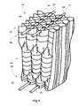
- FIG. 2 A perspective view of a built-in element 10 according to the invention, that of several juxtaposed molded plastic mats 12 with several juxtaposed and offset laterally Half tube sections 14,16 and 18 and with several end quarter-tube sections 20 and 22 is constructed as shown in FIG. 2, is shown in Fig. 1.
- Adjacent plastic mats provided with grid or strut structures 12 are each arranged against each other, so that the mounting element 10 several rows of juxtaposed and staggered along its extension Tubes 24 has.
- the plastic mats 12 are mutually by (Pull) rods 25 connected, which is indicated in Fig. 1.
- Each plastic mat 12 has between adjacent half tube sections extending longitudinal struts 26,28 and 30 and at the longitudinal edges extending edge struts 32. Adjacent longitudinal struts are interconnected interconnected by arcuate transverse struts 34. From These cross struts 34 protrude in the longitudinal direction of the half tube sections pin From 36, in turn, provided with protruding projections 38 are.
- the areas between the arcuate transverse webs On the other hand, 34 are basically open. But here it is in principle conceivable, if some of these areas are closed. It is also possible in that the pins 36 branching off from arcuate transverse struts 34 on both sides of the transverse struts 34 and relative to adjacent cross struts against each other are directed and may also mesh with each other. It is useful if the pin 36 as shown in Fig. 2, adjacent arcuate transverse struts 34 do not interconnect. However, it is possible that connecting struts between adjacent arcuate Cross struts 34 are present. Furthermore, the end half-tube sections 14 a greater axial extent than the opposite end-side Half tube sections 18 on. This applies in a similar way for the end quarter-tube sections 20 and 22.
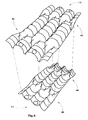
- FIG. 2 and 3 show two alternative ways of composition adjacent lattice mats 12. While in the situation shown in FIG. 3, the transition regions 40 of the adjacent Plastic mats 12 are opposite each other, these transition areas 40 in the assembly situation according to FIG. 4 in the axial direction of the Half and quarter tube sections offset from each other.
Landscapes
- Engineering & Computer Science (AREA)
- Physics & Mathematics (AREA)
- Thermal Sciences (AREA)
- Mechanical Engineering (AREA)
- General Engineering & Computer Science (AREA)
- Heat-Exchange Devices With Radiators And Conduit Assemblies (AREA)
- Mattresses And Other Support Structures For Chairs And Beds (AREA)
- Lining Or Joining Of Plastics Or The Like (AREA)
- Rigid Pipes And Flexible Pipes (AREA)
- Separation Using Semi-Permeable Membranes (AREA)
Abstract
Description
- mehreren geformten Kunststoffmatten, die jeweils nebeneinander liegende Halbröhrenabschnitte aufweisen, wobei jeder Halbröhrenabschnitt quer zu seiner Längserstreckung verlaufende Querstreben mit von diesen in Längsrichtung der Halbröhrenabschnitte abstehenden Zapfen mit wiederum von diesen abstehenden Vorsprüngen aufweist.
- Fig. 1
- eine schematische, perspektivische Seitenansicht eines mit den erfindungsgemäßen geformten Kunststoffmatten aufgebauten Einbauelements,
- Fig. 2
- eine perspektivische Draufsicht auf eine erfindungsgemäß geformte Kunststoffmatte, wie sie für den Aufbau des Einbauelements gemäß Fig. 1 Verwendung findet,
- Fig. 3
- schematisch eine erste alternative Relativanordnung zweier benachbarter Kunststoffmatten des Einbauelements gemäß Fig. 1 und
- Fig 4
- schematisch eine zweite alternative Relativanordnung zweier benachbarter Kunststoffmatten des Einbauelements gemäß Fig. 1.
Claims (7)
- Einbauelement für einen von einem Fluid durchströmbaren Hohlraum wie z.B. in einem Kühlturm mitmehreren geformten Kunststoffmatten (12), die jeweils nebeneinander liegende Halbröhrenabschnitte (14,16,18) aufweisen, wobei jeder Halbröhrenabschnitt (14,16,18) quer zu seiner Längserstreckung verlaufende Querstreben (34) mit von diesen in Längsrichtung der Halbröhrenabschnitte (14,16,18) abstehenden Zapfen (36) mit wiederum von diesen abstehenden Vorsprüngen (38) aufweist.
- Einbauelement nach Anspruch 1, dadurch gekennzeichnet, dass jede Kunststoffmatte (12) mehrere in Längserstreckung der Halbröhrenabschnitte (14,16,18) aufeinander folgende und zueinander seitlich versetzte Halbröhrenabschnitte (14,16,18) aufweist.
- Einbauelement nach Anspruch 2, dadurch gekennzeichnet, dass die Längen der einzelnen in Längserstreckung aufeinander folgenden und seitlich zueinander versetzten Halbröhrenabschnitte (14,16,18) unterschiedlich sind.
- Einbauelement nach Anspruch 2 oder 3, dadurch gekennzeichnet, dass die Übergangsabschnitte (40) zwischen aufeinander folgenden und seitlich versetzten Halbröhrenabschnitten (14,16,18) zur Ober- bzw. Unterseite der Kunststoffmatte (12) geschlossen sind.
- Einbauelement nach einem der Ansprüche 2 bis 4, dadurch gekennzeichnet, dass die Übergangsabschnitte (40) zwischen aufeinander folgenden und seitlich versetzten Halbröhrenabschnitten (14,16,18) Verstrebungen (42) aufweisen.
- Einbauelement nach einem der Ansprüche 2 bis 5, dadurch gekennzeichnet, dass zwischen jeweils nebeneinander liegenden Halbröhrenabschnitten (14,16,18) eine Längsstrebe (26,28,30) verläuft, die sich im Übergangsabschnitt (40) zu in Längsrichtung folgenden und seitlich versetzt angeordneten Halbröhrenabschnitten (14,16,18) teilen, schräg verlaufen und in die Längsstreben (26,28,30) zwischen diesen Halbröhrenabschnitten (14,16,18) übergehen.
- Einbauelement nach einem der Ansprüche 1 bis 7, dadurch gekennzeichnet, dass die Halbröhrenabschnitte (14,16,18) im Querschnitt halbrundform, dreieckig oder mehreckig ausgebildet sind.
Priority Applications (2)
| Application Number | Priority Date | Filing Date | Title |
|---|---|---|---|
| PL05104262T PL1598628T3 (pl) | 2004-05-19 | 2005-05-19 | Element wbudowywany do pustej przestrzeni, przez którą może przepływać płyn |
| SI200531969T SI1598628T1 (sl) | 2004-05-19 | 2005-05-19 | Vložek za votel prostor, v katerem lahko teče tekočina |
Applications Claiming Priority (2)
| Application Number | Priority Date | Filing Date | Title |
|---|---|---|---|
| DE102004025336A DE102004025336B4 (de) | 2004-05-19 | 2004-05-19 | Einbauelement für einen von einem Fluid durchströmbaren Hohlraum |
| DE102004025336 | 2004-05-19 |
Publications (3)
| Publication Number | Publication Date |
|---|---|
| EP1598628A2 true EP1598628A2 (de) | 2005-11-23 |
| EP1598628A3 EP1598628A3 (de) | 2008-02-13 |
| EP1598628B1 EP1598628B1 (de) | 2015-03-18 |
Family
ID=34939900
Family Applications (1)
| Application Number | Title | Priority Date | Filing Date |
|---|---|---|---|
| EP05104262.0A Expired - Lifetime EP1598628B1 (de) | 2004-05-19 | 2005-05-19 | Einbauelement für einen von einem Fluid durchströmbaren Hohlraum |
Country Status (6)
| Country | Link |
|---|---|
| EP (1) | EP1598628B1 (de) |
| DE (1) | DE102004025336B4 (de) |
| ES (1) | ES2537757T3 (de) |
| PL (1) | PL1598628T3 (de) |
| PT (1) | PT1598628E (de) |
| SI (1) | SI1598628T1 (de) |
Cited By (1)
| Publication number | Priority date | Publication date | Assignee | Title |
|---|---|---|---|---|
| EP2881694B1 (de) | 2013-12-06 | 2019-02-20 | Hewitech GmbH & Co. KG | Einbaueinrichtung für eine Vorrichtung zur Behandlung eines strömenden Fluids |
Families Citing this family (2)
| Publication number | Priority date | Publication date | Assignee | Title |
|---|---|---|---|---|
| DE102006005114A1 (de) * | 2006-02-04 | 2007-08-09 | Hewitech Gmbh & Co. Kg | Einbauten für Rieselkühler, insbesondere für Kühltürme und Kunststofflage für derartige Einbauten |
| DE102010007873A1 (de) * | 2010-02-13 | 2011-08-18 | Hewitech GmbH & Co. KG, 48607 | Einbau für einen Kühlturm und Kühlturm mit mehreren derartigen Einbauten |
Citations (4)
| Publication number | Priority date | Publication date | Assignee | Title |
|---|---|---|---|---|
| EP0825407A2 (de) | 1996-08-10 | 1998-02-25 | 2H KUNSTSTOFF GmbH | Einbauelement für Wärmetauscher |
| DE19733480A1 (de) | 1997-08-01 | 1999-02-04 | Gea Energietechnik Gmbh | Einbaupackung zum Stoff- und/oder Wärmeaustausch zwischen Gasen und Flüssigkeiten |
| DE19819945A1 (de) | 1998-05-05 | 1999-11-18 | Frank Dirkskoetter | Verfahren sowie Vorrichtung zur Herstellung eines Einbauelements für einen Wärmetauscher, insbesondere in einem Kühlturm |
| US6241222B1 (en) | 1998-07-14 | 2001-06-05 | Lantec Products, Inc. | Stacked packing with spacing features |
Family Cites Families (9)
| Publication number | Priority date | Publication date | Assignee | Title |
|---|---|---|---|---|
| US3281307A (en) * | 1962-11-05 | 1966-10-25 | Dow Chemical Co | Packing |
| GB1286244A (en) * | 1968-08-06 | 1972-08-23 | Ronald Priestley | Packings for gas/liquid contact apparatus |
| JPS4920071A (de) * | 1972-04-14 | 1974-02-22 | ||
| DE2950803C2 (de) * | 1979-12-17 | 1982-01-21 | Ernst, Günter, Prof.Dr.-Ing., 7500 Karlsruhe | Vorrichtung zum Abkühlen von Kühlwasser |
| US4385012A (en) * | 1980-01-28 | 1983-05-24 | Ronald Priestley | Phase-contacting apparatus |
| GB8304683D0 (en) * | 1983-02-19 | 1983-03-23 | Wigley A F | Moisture eliminator |
| US4905313A (en) * | 1989-03-17 | 1990-02-27 | Custodis-Ecodyne | Gas/liquid contact apparatus |
| ATE129561T1 (de) * | 1992-02-01 | 1995-11-15 | 2 H Kunststoff Gmbh | Einbauelement für wärmetauscher-, stoffaustauscher- oder bioreaktor-systeme. |
| US5204027A (en) * | 1992-02-04 | 1993-04-20 | Armstrong Charles M | Fluid contact panels |
-
2004
- 2004-05-19 DE DE102004025336A patent/DE102004025336B4/de not_active Expired - Fee Related
-
2005
- 2005-05-19 ES ES05104262.0T patent/ES2537757T3/es not_active Expired - Lifetime
- 2005-05-19 SI SI200531969T patent/SI1598628T1/sl unknown
- 2005-05-19 PT PT51042620T patent/PT1598628E/pt unknown
- 2005-05-19 EP EP05104262.0A patent/EP1598628B1/de not_active Expired - Lifetime
- 2005-05-19 PL PL05104262T patent/PL1598628T3/pl unknown
Patent Citations (4)
| Publication number | Priority date | Publication date | Assignee | Title |
|---|---|---|---|---|
| EP0825407A2 (de) | 1996-08-10 | 1998-02-25 | 2H KUNSTSTOFF GmbH | Einbauelement für Wärmetauscher |
| DE19733480A1 (de) | 1997-08-01 | 1999-02-04 | Gea Energietechnik Gmbh | Einbaupackung zum Stoff- und/oder Wärmeaustausch zwischen Gasen und Flüssigkeiten |
| DE19819945A1 (de) | 1998-05-05 | 1999-11-18 | Frank Dirkskoetter | Verfahren sowie Vorrichtung zur Herstellung eines Einbauelements für einen Wärmetauscher, insbesondere in einem Kühlturm |
| US6241222B1 (en) | 1998-07-14 | 2001-06-05 | Lantec Products, Inc. | Stacked packing with spacing features |
Cited By (1)
| Publication number | Priority date | Publication date | Assignee | Title |
|---|---|---|---|---|
| EP2881694B1 (de) | 2013-12-06 | 2019-02-20 | Hewitech GmbH & Co. KG | Einbaueinrichtung für eine Vorrichtung zur Behandlung eines strömenden Fluids |
Also Published As
| Publication number | Publication date |
|---|---|
| PL1598628T3 (pl) | 2015-08-31 |
| ES2537757T3 (es) | 2015-06-11 |
| EP1598628A3 (de) | 2008-02-13 |
| PT1598628E (pt) | 2015-07-02 |
| SI1598628T1 (sl) | 2015-10-30 |
| DE102004025336A1 (de) | 2005-12-15 |
| DE102004025336B4 (de) | 2006-06-29 |
| EP1598628B1 (de) | 2015-03-18 |
Similar Documents
| Publication | Publication Date | Title |
|---|---|---|
| DE4111451A1 (de) | Rieseleinbau-element fuer kuehltuerme | |
| DE10220532A1 (de) | Wärmetauscher | |
| CH493814A (de) | Wabenförmiger Einbau für einen Rieselkühler | |
| EP2310756B1 (de) | Einbauelement zum einbau in einer vorrichtung zur befeuchtung, reinigung und/oder kuehlung eines fluids, insbesondere gases wie z.b. luft, und verfahren zur herstellung eines einbaukörpers mit einem solchen einbauelement | |
| DE3419734A1 (de) | Luftgekuehlter oberflaechenkondensator | |
| EP1598628B1 (de) | Einbauelement für einen von einem Fluid durchströmbaren Hohlraum | |
| EP3583360B1 (de) | Rieselkörper | |
| DE10309742B4 (de) | Abstandhalter | |
| DE102005051882B4 (de) | Einbauelement für einen Wärmetauscher oder zum Einbau im Erdreich zu Drainagezwecken | |
| WO1998006996A1 (de) | Einbauelement für wärmetauscher | |
| EP0932010B1 (de) | Wärmeübertrager | |
| EP4067781B1 (de) | Kälteregister zur kaltlufterzeugung mit enteisungseinrichtung | |
| DE102006011794B3 (de) | Wärmetauscher | |
| DE4040875C2 (de) | Ölkühler | |
| DE202011110101U1 (de) | Wärmetauscheranordung | |
| DE102014015916A1 (de) | Roststab und Rost für eine Schubrostfeuerung | |
| EP4495532B1 (de) | Gewellte gittermatte | |
| EP2729750B1 (de) | Wärmetauscheranordnung | |
| EP2881170B1 (de) | Einbauelement für eine Vorrichtung zur Behandlung eines Fluids | |
| DE202009004513U1 (de) | Gitterplatten mit Abstandshaltern | |
| AT404186B (de) | Wärmetauscher, insbesondere für fliessbetttrockner sowie verfahren zu dessen herstellung | |
| DE102006005114A1 (de) | Einbauten für Rieselkühler, insbesondere für Kühltürme und Kunststofflage für derartige Einbauten | |
| DE102006005112A1 (de) | Kunststofflage für ein Einbauelement zum Einbau in einem Riesenkühler, insbesondere Kühlturm zu Kühlzwecken oder zum Einbau ins Erdreich zu Drainagezwecken | |
| AT273829B (de) | Straßenablauf | |
| DE202013009854U1 (de) | Einbauelement für eine Vorrichtung zur Behandlung eines Fluids |
Legal Events
| Date | Code | Title | Description |
|---|---|---|---|
| PUAI | Public reference made under article 153(3) epc to a published international application that has entered the european phase |
Free format text: ORIGINAL CODE: 0009012 |
|
| AK | Designated contracting states |
Kind code of ref document: A2 Designated state(s): AT BE BG CH CY CZ DE DK EE ES FI FR GB GR HU IE IS IT LI LT LU MC NL PL PT RO SE SI SK TR |
|
| AX | Request for extension of the european patent |
Extension state: AL BA HR LV MK YU |
|
| PUAL | Search report despatched |
Free format text: ORIGINAL CODE: 0009013 |
|
| AK | Designated contracting states |
Kind code of ref document: A3 Designated state(s): AT BE BG CH CY CZ DE DK EE ES FI FR GB GR HU IE IS IT LI LT LU MC NL PL PT RO SE SI SK TR |
|
| AX | Request for extension of the european patent |
Extension state: AL BA HR LV MK YU |
|
| 17P | Request for examination filed |
Effective date: 20080412 |
|
| AKX | Designation fees paid |
Designated state(s): AT BE BG CH CY CZ DE DK EE ES FI FR GB GR HU IE IS IT LI LT LU MC NL PL PT RO SE SI SK TR |
|
| 17Q | First examination report despatched |
Effective date: 20100630 |
|
| GRAP | Despatch of communication of intention to grant a patent |
Free format text: ORIGINAL CODE: EPIDOSNIGR1 |
|
| INTG | Intention to grant announced |
Effective date: 20141001 |
|
| GRAS | Grant fee paid |
Free format text: ORIGINAL CODE: EPIDOSNIGR3 |
|
| GRAA | (expected) grant |
Free format text: ORIGINAL CODE: 0009210 |
|
| AK | Designated contracting states |
Kind code of ref document: B1 Designated state(s): AT BE BG CH CY CZ DE DK EE ES FI FR GB GR HU IE IS IT LI LT LU MC NL PL PT RO SE SI SK TR |
|
| REG | Reference to a national code |
Ref country code: GB Ref legal event code: FG4D Free format text: NOT ENGLISH |
|
| REG | Reference to a national code |
Ref country code: CH Ref legal event code: EP |
|
| REG | Reference to a national code |
Ref country code: IE Ref legal event code: FG4D Free format text: LANGUAGE OF EP DOCUMENT: GERMAN |
|
| REG | Reference to a national code |
Ref country code: AT Ref legal event code: REF Ref document number: 716840 Country of ref document: AT Kind code of ref document: T Effective date: 20150415 |
|
| REG | Reference to a national code |
Ref country code: DE Ref legal event code: R096 Ref document number: 502005014720 Country of ref document: DE Effective date: 20150423 |
|
| REG | Reference to a national code |
Ref country code: RO Ref legal event code: EPE |
|
| REG | Reference to a national code |
Ref country code: ES Ref legal event code: FG2A Ref document number: 2537757 Country of ref document: ES Kind code of ref document: T3 Effective date: 20150611 |
|
| REG | Reference to a national code |
Ref country code: NL Ref legal event code: T3 |
|
| REG | Reference to a national code |
Ref country code: PT Ref legal event code: SC4A Free format text: AVAILABILITY OF NATIONAL TRANSLATION Effective date: 20150526 |
|
| REG | Reference to a national code |
Ref country code: GR Ref legal event code: EP Ref document number: 20150401130 Country of ref document: GR Effective date: 20150618 |
|
| PG25 | Lapsed in a contracting state [announced via postgrant information from national office to epo] |
Ref country code: FI Free format text: LAPSE BECAUSE OF FAILURE TO SUBMIT A TRANSLATION OF THE DESCRIPTION OR TO PAY THE FEE WITHIN THE PRESCRIBED TIME-LIMIT Effective date: 20150318 Ref country code: LT Free format text: LAPSE BECAUSE OF FAILURE TO SUBMIT A TRANSLATION OF THE DESCRIPTION OR TO PAY THE FEE WITHIN THE PRESCRIBED TIME-LIMIT Effective date: 20150318 Ref country code: SE Free format text: LAPSE BECAUSE OF FAILURE TO SUBMIT A TRANSLATION OF THE DESCRIPTION OR TO PAY THE FEE WITHIN THE PRESCRIBED TIME-LIMIT Effective date: 20150318 |
|
| PGFP | Annual fee paid to national office [announced via postgrant information from national office to epo] |
Ref country code: RO Payment date: 20150512 Year of fee payment: 11 Ref country code: ES Payment date: 20150525 Year of fee payment: 11 Ref country code: CH Payment date: 20150529 Year of fee payment: 11 Ref country code: BG Payment date: 20150522 Year of fee payment: 11 Ref country code: TR Payment date: 20150615 Year of fee payment: 11 |
|
| REG | Reference to a national code |
Ref country code: LT Ref legal event code: MG4D |
|
| PGFP | Annual fee paid to national office [announced via postgrant information from national office to epo] |
Ref country code: AT Payment date: 20150525 Year of fee payment: 11 Ref country code: GR Payment date: 20150604 Year of fee payment: 11 Ref country code: NL Payment date: 20150518 Year of fee payment: 11 Ref country code: BE Payment date: 20150513 Year of fee payment: 11 |
|
| REG | Reference to a national code |
Ref country code: PL Ref legal event code: T3 |
|
| REG | Reference to a national code |
Ref country code: SK Ref legal event code: T3 Ref document number: E 18727 Country of ref document: SK |
|
| PG25 | Lapsed in a contracting state [announced via postgrant information from national office to epo] |
Ref country code: EE Free format text: LAPSE BECAUSE OF FAILURE TO SUBMIT A TRANSLATION OF THE DESCRIPTION OR TO PAY THE FEE WITHIN THE PRESCRIBED TIME-LIMIT Effective date: 20150318 |
|
| PGFP | Annual fee paid to national office [announced via postgrant information from national office to epo] |
Ref country code: SK Payment date: 20150513 Year of fee payment: 11 Ref country code: PT Payment date: 20150709 Year of fee payment: 11 |
|
| PG25 | Lapsed in a contracting state [announced via postgrant information from national office to epo] |
Ref country code: IS Free format text: LAPSE BECAUSE OF FAILURE TO SUBMIT A TRANSLATION OF THE DESCRIPTION OR TO PAY THE FEE WITHIN THE PRESCRIBED TIME-LIMIT Effective date: 20150718 |
|
| PGFP | Annual fee paid to national office [announced via postgrant information from national office to epo] |
Ref country code: SI Payment date: 20150515 Year of fee payment: 11 Ref country code: HU Payment date: 20150508 Year of fee payment: 11 |
|
| REG | Reference to a national code |
Ref country code: DE Ref legal event code: R097 Ref document number: 502005014720 Country of ref document: DE |
|
| REG | Reference to a national code |
Ref country code: HU Ref legal event code: AG4A Ref document number: E024803 Country of ref document: HU |
|
| PLBE | No opposition filed within time limit |
Free format text: ORIGINAL CODE: 0009261 |
|
| STAA | Information on the status of an ep patent application or granted ep patent |
Free format text: STATUS: NO OPPOSITION FILED WITHIN TIME LIMIT |
|
| PG25 | Lapsed in a contracting state [announced via postgrant information from national office to epo] |
Ref country code: MC Free format text: LAPSE BECAUSE OF FAILURE TO SUBMIT A TRANSLATION OF THE DESCRIPTION OR TO PAY THE FEE WITHIN THE PRESCRIBED TIME-LIMIT Effective date: 20150318 Ref country code: DK Free format text: LAPSE BECAUSE OF FAILURE TO SUBMIT A TRANSLATION OF THE DESCRIPTION OR TO PAY THE FEE WITHIN THE PRESCRIBED TIME-LIMIT Effective date: 20150318 Ref country code: LU Free format text: LAPSE BECAUSE OF FAILURE TO SUBMIT A TRANSLATION OF THE DESCRIPTION OR TO PAY THE FEE WITHIN THE PRESCRIBED TIME-LIMIT Effective date: 20150519 |
|
| 26N | No opposition filed |
Effective date: 20151221 |
|
| REG | Reference to a national code |
Ref country code: IE Ref legal event code: MM4A |
|
| PG25 | Lapsed in a contracting state [announced via postgrant information from national office to epo] |
Ref country code: IE Free format text: LAPSE BECAUSE OF NON-PAYMENT OF DUE FEES Effective date: 20150519 |
|
| REG | Reference to a national code |
Ref country code: FR Ref legal event code: PLFP Year of fee payment: 12 |
|
| PG25 | Lapsed in a contracting state [announced via postgrant information from national office to epo] |
Ref country code: BE Free format text: LAPSE BECAUSE OF NON-PAYMENT OF DUE FEES Effective date: 20160531 |
|
| REG | Reference to a national code |
Ref country code: CH Ref legal event code: PL |
|
| REG | Reference to a national code |
Ref country code: NL Ref legal event code: MM Effective date: 20160601 |
|
| REG | Reference to a national code |
Ref country code: AT Ref legal event code: MM01 Ref document number: 716840 Country of ref document: AT Kind code of ref document: T Effective date: 20160519 |
|
| PG25 | Lapsed in a contracting state [announced via postgrant information from national office to epo] |
Ref country code: CH Free format text: LAPSE BECAUSE OF NON-PAYMENT OF DUE FEES Effective date: 20160531 Ref country code: RO Free format text: LAPSE BECAUSE OF NON-PAYMENT OF DUE FEES Effective date: 20160519 Ref country code: LI Free format text: LAPSE BECAUSE OF NON-PAYMENT OF DUE FEES Effective date: 20160531 Ref country code: SK Free format text: LAPSE BECAUSE OF NON-PAYMENT OF DUE FEES Effective date: 20160519 |
|
| REG | Reference to a national code |
Ref country code: GR Ref legal event code: ML Ref document number: 20150401130 Country of ref document: GR Effective date: 20161207 Ref country code: SK Ref legal event code: MM4A Ref document number: E 18727 Country of ref document: SK Effective date: 20160519 |
|
| PG25 | Lapsed in a contracting state [announced via postgrant information from national office to epo] |
Ref country code: NL Free format text: LAPSE BECAUSE OF NON-PAYMENT OF DUE FEES Effective date: 20160601 Ref country code: GR Free format text: LAPSE BECAUSE OF NON-PAYMENT OF DUE FEES Effective date: 20161207 Ref country code: AT Free format text: LAPSE BECAUSE OF NON-PAYMENT OF DUE FEES Effective date: 20160519 Ref country code: BG Free format text: LAPSE BECAUSE OF NON-PAYMENT OF DUE FEES Effective date: 20161130 |
|
| REG | Reference to a national code |
Ref country code: SI Ref legal event code: KO00 Effective date: 20170216 |
|
| PG25 | Lapsed in a contracting state [announced via postgrant information from national office to epo] |
Ref country code: HU Free format text: LAPSE BECAUSE OF NON-PAYMENT OF DUE FEES Effective date: 20160520 |
|
| REG | Reference to a national code |
Ref country code: FR Ref legal event code: PLFP Year of fee payment: 13 |
|
| PG25 | Lapsed in a contracting state [announced via postgrant information from national office to epo] |
Ref country code: PT Free format text: LAPSE BECAUSE OF NON-PAYMENT OF DUE FEES Effective date: 20170220 Ref country code: SI Free format text: LAPSE BECAUSE OF NON-PAYMENT OF DUE FEES Effective date: 20160520 |
|
| PG25 | Lapsed in a contracting state [announced via postgrant information from national office to epo] |
Ref country code: CY Free format text: LAPSE BECAUSE OF FAILURE TO SUBMIT A TRANSLATION OF THE DESCRIPTION OR TO PAY THE FEE WITHIN THE PRESCRIBED TIME-LIMIT Effective date: 20150318 |
|
| PG25 | Lapsed in a contracting state [announced via postgrant information from national office to epo] |
Ref country code: ES Free format text: LAPSE BECAUSE OF NON-PAYMENT OF DUE FEES Effective date: 20160520 |
|
| REG | Reference to a national code |
Ref country code: FR Ref legal event code: PLFP Year of fee payment: 14 |
|
| PGFP | Annual fee paid to national office [announced via postgrant information from national office to epo] |
Ref country code: FR Payment date: 20180625 Year of fee payment: 14 |
|
| PGFP | Annual fee paid to national office [announced via postgrant information from national office to epo] |
Ref country code: DE Payment date: 20180626 Year of fee payment: 14 Ref country code: IT Payment date: 20180622 Year of fee payment: 14 Ref country code: GB Payment date: 20180626 Year of fee payment: 14 |
|
| PGFP | Annual fee paid to national office [announced via postgrant information from national office to epo] |
Ref country code: PL Payment date: 20180710 Year of fee payment: 14 Ref country code: CZ Payment date: 20180709 Year of fee payment: 14 |
|
| REG | Reference to a national code |
Ref country code: ES Ref legal event code: FD2A Effective date: 20181204 |
|
| REG | Reference to a national code |
Ref country code: DE Ref legal event code: R119 Ref document number: 502005014720 Country of ref document: DE |
|
| GBPC | Gb: european patent ceased through non-payment of renewal fee |
Effective date: 20190519 |
|
| PG25 | Lapsed in a contracting state [announced via postgrant information from national office to epo] |
Ref country code: CZ Free format text: LAPSE BECAUSE OF NON-PAYMENT OF DUE FEES Effective date: 20190519 |
|
| PG25 | Lapsed in a contracting state [announced via postgrant information from national office to epo] |
Ref country code: DE Free format text: LAPSE BECAUSE OF NON-PAYMENT OF DUE FEES Effective date: 20191203 Ref country code: IT Free format text: LAPSE BECAUSE OF NON-PAYMENT OF DUE FEES Effective date: 20190519 Ref country code: GB Free format text: LAPSE BECAUSE OF NON-PAYMENT OF DUE FEES Effective date: 20190519 |
|
| PG25 | Lapsed in a contracting state [announced via postgrant information from national office to epo] |
Ref country code: FR Free format text: LAPSE BECAUSE OF NON-PAYMENT OF DUE FEES Effective date: 20190531 |
|
| PG25 | Lapsed in a contracting state [announced via postgrant information from national office to epo] |
Ref country code: PL Free format text: LAPSE BECAUSE OF NON-PAYMENT OF DUE FEES Effective date: 20190519 |
|
| PG25 | Lapsed in a contracting state [announced via postgrant information from national office to epo] |
Ref country code: TR Free format text: LAPSE BECAUSE OF NON-PAYMENT OF DUE FEES Effective date: 20160519 |