EP1598623A2 - Dispositif d'isolation de vibration pour réfrigérateur de vin - Google Patents
Dispositif d'isolation de vibration pour réfrigérateur de vin Download PDFInfo
- Publication number
- EP1598623A2 EP1598623A2 EP04293148A EP04293148A EP1598623A2 EP 1598623 A2 EP1598623 A2 EP 1598623A2 EP 04293148 A EP04293148 A EP 04293148A EP 04293148 A EP04293148 A EP 04293148A EP 1598623 A2 EP1598623 A2 EP 1598623A2
- Authority
- EP
- European Patent Office
- Prior art keywords
- base plate
- main body
- springs
- fixing plates
- axial direction
- Prior art date
- Legal status (The legal status is an assumption and is not a legal conclusion. Google has not performed a legal analysis and makes no representation as to the accuracy of the status listed.)
- Granted
Links
Images


Classifications
-
- H—ELECTRICITY
- H10—SEMICONDUCTOR DEVICES; ELECTRIC SOLID-STATE DEVICES NOT OTHERWISE PROVIDED FOR
- H10W—GENERIC PACKAGES, INTERCONNECTIONS, CONNECTORS OR OTHER CONSTRUCTIONAL DETAILS OF DEVICES COVERED BY CLASS H10
- H10W40/00—Arrangements for thermal protection or thermal control
- H10W40/20—Arrangements for cooling
- H10W40/28—Arrangements for cooling comprising Peltier coolers
-
- F—MECHANICAL ENGINEERING; LIGHTING; HEATING; WEAPONS; BLASTING
- F25—REFRIGERATION OR COOLING; COMBINED HEATING AND REFRIGERATION SYSTEMS; HEAT PUMP SYSTEMS; MANUFACTURE OR STORAGE OF ICE; LIQUEFACTION SOLIDIFICATION OF GASES
- F25D—REFRIGERATORS; COLD ROOMS; ICE-BOXES; COOLING OR FREEZING APPARATUS NOT OTHERWISE PROVIDED FOR
- F25D23/00—General constructional features
- F25D23/006—General constructional features for mounting refrigerating machinery components
-
- F—MECHANICAL ENGINEERING; LIGHTING; HEATING; WEAPONS; BLASTING
- F16—ENGINEERING ELEMENTS AND UNITS; GENERAL MEASURES FOR PRODUCING AND MAINTAINING EFFECTIVE FUNCTIONING OF MACHINES OR INSTALLATIONS; THERMAL INSULATION IN GENERAL
- F16F—SPRINGS; SHOCK-ABSORBERS; MEANS FOR DAMPING VIBRATION
- F16F15/00—Suppression of vibrations in systems; Means or arrangements for avoiding or reducing out-of-balance forces, e.g. due to motion
- F16F15/02—Suppression of vibrations of non-rotating, e.g. reciprocating systems; Suppression of vibrations of rotating systems by use of members not moving with the rotating systems
- F16F15/04—Suppression of vibrations of non-rotating, e.g. reciprocating systems; Suppression of vibrations of rotating systems by use of members not moving with the rotating systems using elastic means
- F16F15/06—Suppression of vibrations of non-rotating, e.g. reciprocating systems; Suppression of vibrations of rotating systems by use of members not moving with the rotating systems using elastic means with metal springs
- F16F15/067—Suppression of vibrations of non-rotating, e.g. reciprocating systems; Suppression of vibrations of rotating systems by use of members not moving with the rotating systems using elastic means with metal springs using only wound springs
-
- H—ELECTRICITY
- H05—ELECTRIC TECHNIQUES NOT OTHERWISE PROVIDED FOR
- H05K—PRINTED CIRCUITS; CASINGS OR CONSTRUCTIONAL DETAILS OF ELECTRIC APPARATUS; MANUFACTURE OF ASSEMBLAGES OF ELECTRICAL COMPONENTS
- H05K1/00—Printed circuits
- H05K1/02—Details
- H05K1/0201—Thermal arrangements, e.g. for cooling, heating or preventing overheating
- H05K1/0203—Cooling of mounted components
-
- F—MECHANICAL ENGINEERING; LIGHTING; HEATING; WEAPONS; BLASTING
- F25—REFRIGERATION OR COOLING; COMBINED HEATING AND REFRIGERATION SYSTEMS; HEAT PUMP SYSTEMS; MANUFACTURE OR STORAGE OF ICE; LIQUEFACTION SOLIDIFICATION OF GASES
- F25B—REFRIGERATION MACHINES, PLANTS OR SYSTEMS; COMBINED HEATING AND REFRIGERATION SYSTEMS; HEAT PUMP SYSTEMS
- F25B2500/00—Problems to be solved
- F25B2500/13—Vibrations
-
- F—MECHANICAL ENGINEERING; LIGHTING; HEATING; WEAPONS; BLASTING
- F25—REFRIGERATION OR COOLING; COMBINED HEATING AND REFRIGERATION SYSTEMS; HEAT PUMP SYSTEMS; MANUFACTURE OR STORAGE OF ICE; LIQUEFACTION SOLIDIFICATION OF GASES
- F25D—REFRIGERATORS; COLD ROOMS; ICE-BOXES; COOLING OR FREEZING APPARATUS NOT OTHERWISE PROVIDED FOR
- F25D2331/00—Details or arrangements of other cooling or freezing apparatus not provided for in other groups of this subclass
- F25D2331/80—Type of cooled receptacles
- F25D2331/803—Bottles
-
- Y—GENERAL TAGGING OF NEW TECHNOLOGICAL DEVELOPMENTS; GENERAL TAGGING OF CROSS-SECTIONAL TECHNOLOGIES SPANNING OVER SEVERAL SECTIONS OF THE IPC; TECHNICAL SUBJECTS COVERED BY FORMER USPC CROSS-REFERENCE ART COLLECTIONS [XRACs] AND DIGESTS
- Y10—TECHNICAL SUBJECTS COVERED BY FORMER USPC
- Y10S—TECHNICAL SUBJECTS COVERED BY FORMER USPC CROSS-REFERENCE ART COLLECTIONS [XRACs] AND DIGESTS
- Y10S181/00—Acoustics
- Y10S181/403—Refrigerator compresssor muffler
Definitions
- the present invention relates to a wine refrigerator, and more particularly to, a vibration isolation apparatus for a wine refrigerator which can prevent wine bottles stored in the wine refrigerator from being shaken in the operation of the wine refrigerator.
- a refrigeration cycle system is mounted inside a refrigerator.
- An evaporator composing the refrigeration cycle system generates cool air.
- the cool air is circulated inside the refrigerator, for cooling the refrigerator.
- Refrigerators can be classified into various shapes according to structural properties. Also, various types of refrigerators have been developed according to kinds of stored foods.
- the wine refrigerator includes a main body having a storage chamber for storing wines, and a door mounted on one side of the main body, for opening or closing the storage chamber.
- a refrigeration cycle system is formed in the main body.
- a compressor and a condenser of the refrigeration cycle system that generate vibration noise and heat are mounted on a mechanical chamber disposed at the lower portion of the main body.
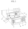
- Fig. 1 is a perspective view illustrating disassembly of the mechanical chamber of the conventional wine refrigerator
- Fig. 2 is a front-sectional view illustrating the mechanical chamber of the conventional wine refrigerator.
- a predetermined size of mounting space R is formed at a bottom rear portion of a main body 100, a predetermined area of bottom plate 110 is fastened to the bottom surface of the main body 100 by using a plurality of screws, and a cover 200 for covering the rear portion of the mounting space R is coupled to the bottom rear surface of the main body 100 by using a plurality of screws 210.
- the bottom plate 110 covers the bottom surface of the mounting space R of the main body 100.
- a compressor 300 is installed on the bottom plate 110 to be positioned inside the mechanical chamber, a control box 400 is mounted on the sidewall of the mechanical chamber, and a defrosted waterspout 500 is installed on the inside top surface of the mechanical chamber to be positioned over the compressor 300. Water generated by frost molten in an evaporator (not shown) is collected in the defrosted waterspout 500 and evaporated.
- the compressor 300 includes an airtight vessel 310, and a plurality of mounting plates 320 coupled to the bottom surface of the airtight vessel 310.
- a suction pipe 330 and a discharge pipe 340 for sucking and discharging refrigerants are connected respectively to the airtight vessel 310.
- the suction pipe 330 is connected to the evaporator, and the discharge pipe 340 is connected to a condenser (not shown) composing the refrigeration cycle system.
- Through holes 321 are formed on the mounting plates 320 of the compressor 300, and through holes 111 corresponding to the through holes 321 of the mounting plates 320 are formed on the bottom plate 110.
- Cylindrical rubber vibration isolators 360 having a predetermined length are positioned between the bottom plate 110 and the mounting plates 320.
- Fixing bolts 370 are inserted into the through holes 111 of the bottom plate 110, the rubber vibration isolators 360 and the through holes 321 of the mounting plates 320, and nuts 380 are fastened to the fixing bolts 370. Accordingly, the mounting plates 320 and the rubber vibration isolators 360 are fixedly coupled to the bottom plate 110.
- Two front legs 120 for supporting the main body 100 are coupled to the front edges of the bottom plate 110 mounted on the bottom surface of the main body 100, and two rear legs 130 for supporting the main body 100 are coupled to the rear portion of the bottom plate 110 at predetermined intervals.
- the front legs 120 can control height, and the rear legs 130 that are rollers can easily transport the refrigerator.
- the front legs 120 and the rear legs 130 contact the bottom surface on which the refrigerator is put, for supporting the refrigerator.
- Reference numerals 350 and 220 denote a dryer and air vent holes, respectively.
- an object of the present invention is to provide a vibration isolation apparatus for a wine refrigerator which can prevent wine bottles stored in the wine refrigerator from being shaken in the operation of the wine refrigerator.
- a vibration isolation apparatus for a wine refrigerator including: a main body having a storage chamber and a mounting space; a base plate disposed at the lower portion of the mounting space of the main body with a predetermined interval from the main body, for forming the mechanical chamber with the mounting space, a compressor being installed on the top surface of the base plate; and an interval maintaining elastic support means coupled between the main body and the base plate, for maintaining a predetermined interval between the main body and the base plate, and elastically supporting the base plate.
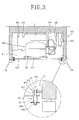
- Fig. 3 is a cross-sectional view illustrating a lower portion of a wine refrigerator including a vibration isolation apparatus in accordance with the present invention.
- same drawing reference numerals are used for the same elements even in different drawings.
- the vibration isolation apparatus for the wine refrigerator includes a main body 100 having a storage chamber (not shown) and a mounting space R, a base plate 600 disposed at the lower portion of the mounting space R of the main body 100 with a predetermined interval from the main body 100, for forming the mechanical chamber with the mounting space R, a compressor 300 being installed on the top surface of the base plate 300, and an interval maintaining elastic support means coupled between the main body 100 and the base plate 600, for maintaining a predetermined interval between the main body 100 and the base plate 600, and elastically supporting the base plate 600.
- the mounting space R of the main body 100 is formed in a predetermined size at the bottom rear portion of the main body 100.
- the base plate 600 is formed in a plate shape having a predetermined thickness.
- the shape of the base plate 600 is equivalent to the shape of the bottom section of the mounting space R of the main body 100, and the size of the base plate 600 is smaller than that of the bottom section of the mounting space R.
- a plurality of through holes 601 are formed on both side ends of the base plate 600.
- the compressor 300 is mounted on the top surface of the base plate 600.
- Elastic vibration isolation means for preventing vibration transmission by spring elasticity S are formed between the compressor 300 and the base plate 600.
- the base plate 600 is installed at the lower portion of the mounting space R of the main body 100 to be positioned on the bottom surface line of the main body 100. Each side of the base plate 600 maintains a predetermined interval from the inner walls of the mounting space R.
- the interval maintaining elastic support means includes fixing plates 610 coupled respectively to both side inner walls of the mounting space R of the main body 100 to be positioned at both end upper portions of the base plate 600, first axial direction support members 620 movably inserted into the fixing plates 610 and the base plate 600 and supported by the fixing plates 610, and springs S1 disposed between the first axial direction support members 620 and the fixing plates 610, for elastically supporting the base plate 600.
- the fixing plates 610 are formed in a rectangular shape having a predetermined width and length.
- a plurality of through holes 611 are formed on the fixing plates 610.
- the fixing plates 610 are coupled to both sidewalls of the mounting space R of the main body 100.
- the length directions of the fixing plates 610 are positioned in the front/rear direction of the main body 100.
- the fixing plates 610 are coupled to the sidewalls of the main body 100 in the vertical direction.
- the fixing plates 610 are positioned at a predetermined height from the bottom surface of the main body 100.
- the fixing plates 610 can be extended and protruded from the inner walls of the mounting space R of the main body 100 and incorporated with the main body 100.
- the fixing plates 610 can be coupled to both sidewalls of the main body 100 in twos, respectively.
- One through hole 611 is formed on each of the fixing plates 610.
- Each of the first axial direction support members 620 includes an axial unit 621 having a predetermined length, a hooking head unit 622 extended from one side end of the axial unit 621 with a predetermined area, and a support nut unit 623 coupled to the other side of the axial unit 621.
- the first axial direction support members 620 are inserted into the through holes 601 of the base plate 600 and the through holes 611 of the fixing plates 610.
- the hooking head units 622 are supported by the top surfaces of the fixing plates 610.
- the springs S1 are inserted onto the axial units 621, and the support nut units 623 are coupled to the axial units 621, for supporting the springs S1.
- the springs S1 are compression springs. One sides of the springs S1 contact the bottom surface of the base plate 600, and the other sides of the springs S1 are supported by the top surfaces of the support nut units 623.
- washers 624 are preferably coupled between the support nut units 623 and the springs S1, for supporting the springs S1.
- the base plate 600 is guided by the first axial direction support members 620, and elastically supported by the springs S1 at the same time.
- the springs S1 slightly sag due to the load of the base plate 600.
- the base plate 600 when vibration occurs on the base plate 600, the base plate 600 is elastically supported by the springs S1 and vibrated. Therefore, the vibration generated on the base plate 600 is absorbed by the springs S1, and thus not transmitted to the main body 100.
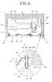
- Fig. 4 is a cross-sectional view illustrating another example of the interval maintaining elastic support means.
- the interval maintaining elastic support means includes fixing plates 610 coupled respectively to both side inner walls of the mounting space R of the main body 100 to be positioned at both end lower portions of the base plate 600, second axial direction support members 630 movably inserted into the fixing plates 610 and the base plate 600 and supported by the base plate 600, and springs S2 disposed between the base plate 600 and the fixing plates 610, for elastically supporting the base plate 600.
- the fixing plates 610 are formed in a rectangular shape having a predetermined width and length.
- a plurality of through holes 611 are formed on the fixing plates 610.
- the fixing plates 610 are coupled to both sidewalls of the mounting space R of the main body 100.
- the length directions of the fixing plates 610 are positioned in the front/rear direction of the main body 100.
- the fixing plates 610 are coupled to the sidewalls of the main body 100 in the vertical direction.
- the bottom surfaces of the fixing plates 610 are positioned on the same plane surface with the bottom surface of the main body 100.
- Both side ends of the base plate 600 are partially curved so that the base plate 600 can be positioned over the fixing plates 610.
- the curved parts of the base plate 600 are positioned over the fixing plates 610 with a predetermined interval from the fixing plates 610.
- the fixing plates 610 can be extended and protruded from the inner walls of the mounting space R of the main body 100 and incorporated with the main body 100.
- the fixing plates 610 can be coupled to both sidewalls of the main body 100 in twos, respectively.
- One through hole 611 is formed on each of the fixing plates 610.
- Each of the second axial direction support members 630 includes an axial unit 631 having a predetermined length, a hooking head unit 632 extended from one side end of the axial unit 631 with a predetermined area, and a support nut unit 633 coupled to the other side of the axial unit 631.
- the second axial direction support members 630 are inserted into the through holes 601 of the base plate 600 and the through holes 611 of the fixing plates 610.
- the hooking head units 632 are supported by the top surfaces of the fixing plates 610.
- the springs S2 When the springs S2 are inserted onto the axial units 631, the springs S2 are positioned between the base plate 600 and the fixing plates 610.
- the springs S2 are compression springs. One sides of the springs S2 contact the bottom surface of the base plate 600, and the other sides of the springs S2 are supported by the top surfaces of the fixing plates 610.
- rubber vibration isolators 640 for absorbing vibration are coupled between the base plate 600 and the second axial direction support members 630, and rubber vibration isolators 640 for absorbing vibration are coupled between the fixing plates 610 and the second axial direction support members 630.
- Each of the rubber vibration isolators 640 includes a cylindrical unit 641 having a predetermined length, and flange units 642 extended from both ends of the cylindrical unit 641 in the horizontal direction.
- One side rubber vibration isolators 640 are disposed between the inner circumferences of the through holes 601 of the base plate 600 and the outer circumferences of the axial units 631 of the second axial direction support members 630.
- the springs S2 and the hooking head units 632 are supported by both side flange units 642 of the rubber vibration isolators 640.
- the other side rubber vibration isolators 640 are disposed between the inner circumferences of the through holes 611 of the fixing plates 610 and the outer circumferences of the axial units 631 of the second axial direction support members 630.
- the springs S2 are supported by one side flange units 642 of the rubber vibration isolators 640.
- the base plate 600 when vibration occurs on the base plate 600, the base plate 600 is elastically supported by the springs S2 and vibrated. Therefore, the vibration generated on the base plate 600 is absorbed by the springs S2, and thus not transmitted to the main body 100.
- the rubber vibration isolators 640 are coupled between the second axial direction support members 630 and the base plate 600 and between the second axial direction support members 630 and the fixing plates 610, thereby efficiently absorbing vibration.
- Fig. 5 is a cross-sectional view illustrating yet another example of the interval maintaining elastic support means.
- the interval maintaining elastic support means includes a plurality of springs S3 for connecting the main body 100 and the base plate 600.
- the springs S3 are tension springs.
- a plurality of hooked units 140 are formed on both side inner walls of the mounting space R of the main body 100, and a plurality of hooked units 602 are formed at both side ends of the base plate 600.
- the hooked units 140 of the main body 100 and the hooked units 602 of the base plate 600 are formed in the same number.
- the tension springs S3 are coupled to the hooked units 140 of the main body 100 and the hooked units 602 of the base plate 600. That is, one sides of the tension springs S3 are hooked on the hooked units 140 of the main body 100, and the other sides thereof are hooked on the hooked units 602 of the base plate 600.
- the base plate 600 is hung in the mounting space R of the main body 100 by the tension springs S3.
- the hooked units 140 of the main body 100, the hooked units 602 of the base plate 600, and the tension springs S3 are formed in fours.
- the base plate 600 when vibration occurs on the base plate 600, the base plate 600 is elastically supported by the springs S3 and vibrated. Therefore, the vibration generated on the base plate 600 is absorbed by the springs S3, and thus not transmitted to the main body 100.
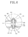
- the elastic vibration isolation means are disposed in four parts between the compressor 300 and the base plate 600.
- the elastic vibration isolation means include third axial direction support members 650 inserted into the mounting plates 320 of the compressor 300 and the base plate 600, springs S4 inserted onto the third axial direction support members 650 to be positioned between the mounting plates 320 and the base plate 600, and rubber gaskets 660 disposed between the mounting plates 320 and the springs S4 and between the base plate 600 and the springs S4, for supporting the springs S4 in the axial direction.
- mounting plates 320 are coupled to the bottom surface of the airtight vessel 310 of the compressor 300, and through holes 321 are formed on the mounting plates 320, respectively.
- Through holes 603 are formed on the base plate 600 facing the through holes 321 of the mounting plates 320.
- Each of the third axial direction support members 650 includes an axial unit 651 having a predetermined length, a hooking head unit 652 extended from one side end of the axial unit 651 with a predetermined area, and a support nut unit 653 coupled to the other side of the axial unit 651.
- the axial units 651 of the third axial direction support members 650 are inserted into the through holes 603 of the base plate 600 and the through holes 321 of the mounting plates 320, and the hooking head units 652 thereof are supported by the bottom surface of the base plate 600.
- the springs S4 are compression springs. When the springs S4 are inserted onto the axial units 651, the springs S4 are positioned between the top surface of the base plate 600 and the bottom surfaces of the mounting plates 320.
- the rubber gaskets 660 are coupled between the support nut units 653 and the mounting plates 320, and washers 654 are inserted between the support nut units 653 and the rubber gaskets 660.
- the elastic vibration isolation means when the compressor 300 compresses refrigerant, if vibration occurs, the mounting plates 320 of the compressor 300 are elastically supported by the rubber gaskets 660 and the springs S4 and vibrated. Therefore, the vibration generated by the compressor 300 is absorbed by the springs S4, and thus rarely transmitted to the base plate 600.
- a defrosted waterspout 500 is installed on the inside top surface of the mounting space R of the main body 100 to be positioned over the compressor 300, and a control box 400 is mounted on the sidewall of the mounting space R of the main body 100.
- a cover (not shown) is coupled to the rear surface of the main body 100, for covering the mounting space R.
- Front legs 120 and rear legs are mounted on the front and rear edges of the bottom surface of the main body 100.
- the rear legs can be mounted on the base plate 100.
- the front legs 120 and the rear legs contact the bottom surface of the indoor space, for supporting the main body 100.
- Reference numerals 310, 330, 340 and 350 denote an airtight vessel, a suction pipe, a discharge pipe and a dryer, respectively.
- the wine refrigerator is operated.
- the evaporator of the refrigeration cycle system generates cool air.
- the storage chamber maintains an optimum temperature by the cool air.
- the compressor 300 installed in the mechanical chamber sucks, compresses and discharges the refrigerants, vibration is generated.
- the vibration generated by the compressor 300 is transmitted to the base plate 600 composing the bottom surface of the mechanical chamber.
- the vibration transmitted to the base plate 600 is absorbed by the interval maintaining elastic support means, and thus rarely transmitted to the main body 100.
- the vibration generated by the compressor 300 is absorbed by the elastic vibration isolation means and then transmitted to the base plate 600. Accordingly, the vibration generated by the compressor 300 is rarely transmitted to the main body 100.
- the vibration isolation apparatus for the wine refrigerator prevents the wine bottles stored in the storage chamber of the main body from being shaken, by preventing the vibration generated by the compressor mounted on the mechanical chamber from being transmitted to the main body in the operation of the wine refrigerator.
- the vibration isolation apparatus for the wine refrigerator can store wines without deteriorating the special taste of the wines.
Landscapes
- Engineering & Computer Science (AREA)
- General Engineering & Computer Science (AREA)
- Physics & Mathematics (AREA)
- Mechanical Engineering (AREA)
- Thermal Sciences (AREA)
- Aviation & Aerospace Engineering (AREA)
- Chemical & Material Sciences (AREA)
- Combustion & Propulsion (AREA)
- Acoustics & Sound (AREA)
- Microelectronics & Electronic Packaging (AREA)
- Vibration Prevention Devices (AREA)
- Compressor (AREA)
- Cold Air Circulating Systems And Constructional Details In Refrigerators (AREA)
Applications Claiming Priority (2)
| Application Number | Priority Date | Filing Date | Title |
|---|---|---|---|
| KR1020040035356A KR100575680B1 (ko) | 2004-05-18 | 2004-05-18 | 방진기능을 구비한 와인 냉장고 |
| KR2004035356 | 2004-05-18 |
Publications (3)
| Publication Number | Publication Date |
|---|---|
| EP1598623A2 true EP1598623A2 (fr) | 2005-11-23 |
| EP1598623A3 EP1598623A3 (fr) | 2006-01-04 |
| EP1598623B1 EP1598623B1 (fr) | 2015-10-14 |
Family
ID=34931670
Family Applications (1)
| Application Number | Title | Priority Date | Filing Date |
|---|---|---|---|
| EP04293148.5A Expired - Lifetime EP1598623B1 (fr) | 2004-05-18 | 2004-12-28 | Dispositif d'isolation de vibration pour réfrigérateur de vin |
Country Status (5)
| Country | Link |
|---|---|
| US (1) | US7398655B2 (fr) |
| EP (1) | EP1598623B1 (fr) |
| JP (1) | JP2005331228A (fr) |
| KR (1) | KR100575680B1 (fr) |
| CN (1) | CN100451502C (fr) |
Cited By (4)
| Publication number | Priority date | Publication date | Assignee | Title |
|---|---|---|---|---|
| DE102006020506A1 (de) * | 2006-04-22 | 2007-10-25 | Rittal Gmbh & Co. Kg | Kühlgerät |
| GB2446301A (en) * | 2007-02-02 | 2008-08-06 | Filton Brewery Ltd | Beverage cooling apparatus |
| ES2489966A1 (es) * | 2013-02-25 | 2014-09-02 | Suspensiones Elásticas Del Norte, S.L. | Amortiguador hídrido con sistema antivuelco |
| EP3242020A1 (fr) * | 2016-05-03 | 2017-11-08 | LG Electronics Inc. | Compresseur linéaire |
Families Citing this family (26)
| Publication number | Priority date | Publication date | Assignee | Title |
|---|---|---|---|---|
| WO2006118217A1 (fr) * | 2005-04-27 | 2006-11-09 | Fukushima Kogyo Co., Ltd. | Refrigerateur |
| CN101113862B (zh) * | 2006-07-28 | 2011-09-21 | 海尔集团公司 | 用于酒冰箱的消振装置 |
| EP1903157A3 (fr) * | 2006-09-19 | 2008-05-14 | Integrated Dynamics Engineering GmbH | Dispositif de protection contre les bruits ambiants |
| KR101408775B1 (ko) * | 2008-01-03 | 2014-06-17 | 동부대우전자 주식회사 | 냉장고의 진동 저감형 콤프 베이스 |
| AT10652U1 (de) * | 2008-02-27 | 2009-07-15 | Acc Austria Gmbh | Vorrichtung zum befestigen des gehäuses eines kältemittelverdichters |
| JP5389369B2 (ja) * | 2008-03-31 | 2014-01-15 | パナソニックヘルスケア株式会社 | 冷却貯蔵庫 |
| EP2300759A1 (fr) * | 2008-05-23 | 2011-03-30 | Aktiebolaget Electrolux | Appareil de froid |
| JP2010216747A (ja) * | 2009-03-18 | 2010-09-30 | Sharp Corp | 冷却庫 |
| CN102506540A (zh) * | 2011-09-20 | 2012-06-20 | 合肥美的荣事达电冰箱有限公司 | 冰箱及用于冰箱的压缩机墙板和压缩机固定组件 |
| CN102758759B (zh) * | 2012-07-27 | 2016-03-16 | 奇瑞汽车股份有限公司 | 空气压缩机的悬置系统 |
| US9249984B2 (en) * | 2012-08-16 | 2016-02-02 | Carrier Corporation | Base pan |
| CN203393698U (zh) * | 2012-11-22 | 2014-01-15 | 三一重工股份有限公司 | 弹性支撑装置、强夯机提升机构及强夯机 |
| MX2015006520A (es) * | 2012-11-23 | 2015-07-21 | Dow Global Technologies Llc | Placa de base de montaje de compresor. |
| WO2014121190A1 (fr) | 2013-02-04 | 2014-08-07 | Metro Industries Inc. | Armoire de réfrigération mobile |
| DE102013221982B4 (de) * | 2013-10-29 | 2023-07-06 | BSH Hausgeräte GmbH | Haushaltsgerät mit einer Wärmepumpe |
| CN104534788B (zh) * | 2014-12-24 | 2017-05-24 | 合肥美的电冰箱有限公司 | 冰箱的底脚组件和冰箱 |
| JP6370723B2 (ja) * | 2015-01-30 | 2018-08-08 | ニチアス株式会社 | 連結具及び遮蔽体 |
| EP3176121B1 (fr) * | 2015-12-02 | 2018-08-08 | KONE Corporation | Agencement de cabine d'ascenseur et procédé pour amortir les vibrations |
| KR102424610B1 (ko) * | 2018-04-10 | 2022-07-25 | 엘지전자 주식회사 | 리니어 압축기 |
| KR20200005087A (ko) * | 2018-07-05 | 2020-01-15 | 주식회사 위니아대우 | 지지체, 이를 포함하는 컴프레서 및 냉장고 |
| CN108891737B (zh) * | 2018-08-16 | 2024-12-06 | 江苏比昂电子材料有限公司 | 一种大型ito靶材储存箱 |
| JP7268832B2 (ja) * | 2018-12-25 | 2023-05-08 | アクア株式会社 | 冷蔵庫 |
| EP4261062A4 (fr) * | 2020-12-11 | 2024-11-13 | Zhejiang Geely Holding Group Co., Ltd. | Système de suspension pour un compresseur de climatiseur de véhicule et véhicule |
| US12104585B2 (en) * | 2021-07-23 | 2024-10-01 | Nokia Shanghai Bell Co., Ltd. | Vibration isolation to protect electrical circuits from vibration-induced damage |
| KR20230164385A (ko) * | 2022-05-25 | 2023-12-04 | 엘지전자 주식회사 | 냉장고 |
| CN116221337B (zh) * | 2023-03-08 | 2025-12-02 | 江苏哲雪冷链设备有限公司 | 一种具有避震功能的改进型螺杆式冷水机组 |
Citations (3)
| Publication number | Priority date | Publication date | Assignee | Title |
|---|---|---|---|---|
| US2117919A (en) | 1936-04-08 | 1938-05-17 | Gen Motors Corp | Refrigerating apparatus |
| US2666302A (en) | 1951-04-06 | 1954-01-19 | Nash Kelvinator Corp | Refrigerating apparatus and cabinet structure |
| US5070708A (en) | 1987-12-29 | 1991-12-10 | Whirlpool Corporation | Floating frame mounting system and method for a refrigerator |
Family Cites Families (6)
| Publication number | Priority date | Publication date | Assignee | Title |
|---|---|---|---|---|
| US2247904A (en) * | 1938-02-03 | 1941-07-01 | Hoover Co | Refrigeration |
| GB554885A (en) * | 1941-05-07 | 1943-06-22 | Westinghouse Electric Int Co | Improvements in or relating to refrigeration apparatus |
| CH228747A (de) * | 1941-07-14 | 1943-09-15 | Bosch Gmbh Robert | Motorverdichter in Kältemaschinen mit auf elastisch nachgiebigen Stützen gelagertem Motorverdichterblock. |
| US3250461A (en) * | 1964-09-08 | 1966-05-10 | Lennox Ind Inc | Hermetic compressor assembly |
| JPS58137633A (ja) * | 1982-02-12 | 1983-08-16 | Matsushita Electric Ind Co Ltd | 圧縮機の支持装置 |
| US5306121A (en) * | 1993-04-23 | 1994-04-26 | Carrier Corporation | Compressor tiered mounting arrangement |
-
2004
- 2004-05-18 KR KR1020040035356A patent/KR100575680B1/ko not_active Expired - Fee Related
- 2004-12-28 EP EP04293148.5A patent/EP1598623B1/fr not_active Expired - Lifetime
-
2005
- 2005-01-10 US US11/030,888 patent/US7398655B2/en not_active Expired - Lifetime
- 2005-01-21 JP JP2005013923A patent/JP2005331228A/ja not_active Withdrawn
- 2005-03-14 CN CNB2005100527773A patent/CN100451502C/zh not_active Expired - Fee Related
Patent Citations (3)
| Publication number | Priority date | Publication date | Assignee | Title |
|---|---|---|---|---|
| US2117919A (en) | 1936-04-08 | 1938-05-17 | Gen Motors Corp | Refrigerating apparatus |
| US2666302A (en) | 1951-04-06 | 1954-01-19 | Nash Kelvinator Corp | Refrigerating apparatus and cabinet structure |
| US5070708A (en) | 1987-12-29 | 1991-12-10 | Whirlpool Corporation | Floating frame mounting system and method for a refrigerator |
Cited By (6)
| Publication number | Priority date | Publication date | Assignee | Title |
|---|---|---|---|---|
| DE102006020506A1 (de) * | 2006-04-22 | 2007-10-25 | Rittal Gmbh & Co. Kg | Kühlgerät |
| DE102006020506B4 (de) * | 2006-04-22 | 2014-05-15 | Rittal Gmbh & Co. Kg | Kühlgerät |
| GB2446301A (en) * | 2007-02-02 | 2008-08-06 | Filton Brewery Ltd | Beverage cooling apparatus |
| ES2489966A1 (es) * | 2013-02-25 | 2014-09-02 | Suspensiones Elásticas Del Norte, S.L. | Amortiguador hídrido con sistema antivuelco |
| EP3242020A1 (fr) * | 2016-05-03 | 2017-11-08 | LG Electronics Inc. | Compresseur linéaire |
| US10533545B2 (en) | 2016-05-03 | 2020-01-14 | Lg Electronics Inc. | Linear compressor |
Also Published As
| Publication number | Publication date |
|---|---|
| US7398655B2 (en) | 2008-07-15 |
| CN1699894A (zh) | 2005-11-23 |
| KR20050110385A (ko) | 2005-11-23 |
| EP1598623A3 (fr) | 2006-01-04 |
| CN100451502C (zh) | 2009-01-14 |
| JP2005331228A (ja) | 2005-12-02 |
| EP1598623B1 (fr) | 2015-10-14 |
| US20050257554A1 (en) | 2005-11-24 |
| KR100575680B1 (ko) | 2006-05-03 |
Similar Documents
| Publication | Publication Date | Title |
|---|---|---|
| US7398655B2 (en) | Vibration isolation apparatus for wine refrigerator | |
| US7325412B2 (en) | Vibration-absorbing supporting apparatus of wine refrigerator | |
| US7257961B2 (en) | Vibration reduction type refrigerator | |
| US8931297B2 (en) | Cooling apparatus condenser, and a cooling apparatus including the same | |
| CN101113862B (zh) | 用于酒冰箱的消振装置 | |
| US10254006B2 (en) | Compressor noise suppressing structure and dehumidifier having the same | |
| US2666301A (en) | Mounting refrigerating apparatus | |
| JP5809547B2 (ja) | 冷却貯蔵庫 | |
| US20050255209A1 (en) | Refrigerator for grain | |
| CN222298257U (zh) | 冷柜 | |
| KR200322196Y1 (ko) | 냉장고의응축기방진용지지장치 | |
| JP2002267349A (ja) | 冷却貯蔵庫の棚装置 | |
| KR20050048963A (ko) | 냉장고의 응축기 고정장치 | |
| JP3299648B2 (ja) | 断熱箱体の構造 | |
| TWI542500B (zh) | Frame construction of refrigeration device for vehicle | |
| WO2021217778A1 (fr) | Réfrigérateur | |
| KR20050062079A (ko) | 냉장고의 압축기 진동전달저감구조 | |
| KR20100001484U (ko) | 냉장고용 도어 어셈블리 | |
| JPH06159908A (ja) | 冷蔵庫 | |
| JP2011231977A (ja) | 車載用冷凍装置のフレーム構造 | |
| JPH09311977A (ja) | 温調庫機器 | |
| JPH08193692A (ja) | 圧縮機の固定装置 | |
| JPH1114229A (ja) | 冷蔵庫 | |
| KR20020082675A (ko) | 냉장고의 진동 저감 장치 | |
| JPH09145231A (ja) | 冷却装置 |
Legal Events
| Date | Code | Title | Description |
|---|---|---|---|
| PUAI | Public reference made under article 153(3) epc to a published international application that has entered the european phase |
Free format text: ORIGINAL CODE: 0009012 |
|
| PUAL | Search report despatched |
Free format text: ORIGINAL CODE: 0009013 |
|
| 17P | Request for examination filed |
Effective date: 20050103 |
|
| AK | Designated contracting states |
Kind code of ref document: A2 Designated state(s): AT BE BG CH CY CZ DE DK EE ES FI FR GB GR HU IE IS IT LI LT LU MC NL PL PT RO SE SI SK TR |
|
| AX | Request for extension of the european patent |
Extension state: AL BA HR LV MK YU |
|
| AK | Designated contracting states |
Kind code of ref document: A3 Designated state(s): AT BE BG CH CY CZ DE DK EE ES FI FR GB GR HU IE IS IT LI LT LU MC NL PL PT RO SE SI SK TR |
|
| AX | Request for extension of the european patent |
Extension state: AL BA HR LV MK YU |
|
| RIC1 | Information provided on ipc code assigned before grant |
Ipc: F25D 23/00 20060101AFI20050914BHEP Ipc: F16F 15/067 20060101ALI20051112BHEP |
|
| AKX | Designation fees paid |
Designated state(s): DE FR GB IT NL |
|
| 17Q | First examination report despatched |
Effective date: 20070605 |
|
| GRAP | Despatch of communication of intention to grant a patent |
Free format text: ORIGINAL CODE: EPIDOSNIGR1 |
|
| INTG | Intention to grant announced |
Effective date: 20150625 |
|
| GRAS | Grant fee paid |
Free format text: ORIGINAL CODE: EPIDOSNIGR3 |
|
| GRAA | (expected) grant |
Free format text: ORIGINAL CODE: 0009210 |
|
| AK | Designated contracting states |
Kind code of ref document: B1 Designated state(s): DE FR GB IT NL |
|
| REG | Reference to a national code |
Ref country code: GB Ref legal event code: FG4D |
|
| REG | Reference to a national code |
Ref country code: DE Ref legal event code: R096 Ref document number: 602004048056 Country of ref document: DE |
|
| REG | Reference to a national code |
Ref country code: FR Ref legal event code: PLFP Year of fee payment: 12 |
|
| REG | Reference to a national code |
Ref country code: NL Ref legal event code: FP |
|
| REG | Reference to a national code |
Ref country code: DE Ref legal event code: R097 Ref document number: 602004048056 Country of ref document: DE |
|
| PLBE | No opposition filed within time limit |
Free format text: ORIGINAL CODE: 0009261 |
|
| STAA | Information on the status of an ep patent application or granted ep patent |
Free format text: STATUS: NO OPPOSITION FILED WITHIN TIME LIMIT |
|
| 26N | No opposition filed |
Effective date: 20160715 |
|
| REG | Reference to a national code |
Ref country code: FR Ref legal event code: PLFP Year of fee payment: 13 |
|
| PGFP | Annual fee paid to national office [announced via postgrant information from national office to epo] |
Ref country code: GB Payment date: 20161110 Year of fee payment: 13 Ref country code: FR Payment date: 20161114 Year of fee payment: 13 Ref country code: NL Payment date: 20161108 Year of fee payment: 13 Ref country code: DE Payment date: 20161107 Year of fee payment: 13 |
|
| PGFP | Annual fee paid to national office [announced via postgrant information from national office to epo] |
Ref country code: IT Payment date: 20161215 Year of fee payment: 13 |
|
| REG | Reference to a national code |
Ref country code: DE Ref legal event code: R119 Ref document number: 602004048056 Country of ref document: DE |
|
| REG | Reference to a national code |
Ref country code: NL Ref legal event code: MM Effective date: 20180101 |
|
| GBPC | Gb: european patent ceased through non-payment of renewal fee |
Effective date: 20171228 |
|
| PG25 | Lapsed in a contracting state [announced via postgrant information from national office to epo] |
Ref country code: NL Free format text: LAPSE BECAUSE OF NON-PAYMENT OF DUE FEES Effective date: 20180101 |
|
| REG | Reference to a national code |
Ref country code: FR Ref legal event code: ST Effective date: 20180831 |
|
| PG25 | Lapsed in a contracting state [announced via postgrant information from national office to epo] |
Ref country code: FR Free format text: LAPSE BECAUSE OF NON-PAYMENT OF DUE FEES Effective date: 20180102 Ref country code: DE Free format text: LAPSE BECAUSE OF NON-PAYMENT OF DUE FEES Effective date: 20180703 Ref country code: IT Free format text: LAPSE BECAUSE OF NON-PAYMENT OF DUE FEES Effective date: 20171228 |
|
| PG25 | Lapsed in a contracting state [announced via postgrant information from national office to epo] |
Ref country code: GB Free format text: LAPSE BECAUSE OF NON-PAYMENT OF DUE FEES Effective date: 20171228 |