EP1598551B1 - Dispositif d'injection de carburant - Google Patents
Dispositif d'injection de carburant Download PDFInfo
- Publication number
- EP1598551B1 EP1598551B1 EP05101652A EP05101652A EP1598551B1 EP 1598551 B1 EP1598551 B1 EP 1598551B1 EP 05101652 A EP05101652 A EP 05101652A EP 05101652 A EP05101652 A EP 05101652A EP 1598551 B1 EP1598551 B1 EP 1598551B1
- Authority
- EP
- European Patent Office
- Prior art keywords
- throttle
- pressure
- fuel
- fuel injection
- injection device
- Prior art date
- Legal status (The legal status is an assumption and is not a legal conclusion. Google has not performed a legal analysis and makes no representation as to the accuracy of the status listed.)
- Expired - Fee Related
Links
Images

Classifications
-
- F—MECHANICAL ENGINEERING; LIGHTING; HEATING; WEAPONS; BLASTING
- F02—COMBUSTION ENGINES; HOT-GAS OR COMBUSTION-PRODUCT ENGINE PLANTS
- F02M—SUPPLYING COMBUSTION ENGINES IN GENERAL WITH COMBUSTIBLE MIXTURES OR CONSTITUENTS THEREOF
- F02M57/00—Fuel-injectors combined or associated with other devices
- F02M57/02—Injectors structurally combined with fuel-injection pumps
- F02M57/022—Injectors structurally combined with fuel-injection pumps characterised by the pump drive
- F02M57/025—Injectors structurally combined with fuel-injection pumps characterised by the pump drive hydraulic, e.g. with pressure amplification
-
- F—MECHANICAL ENGINEERING; LIGHTING; HEATING; WEAPONS; BLASTING
- F02—COMBUSTION ENGINES; HOT-GAS OR COMBUSTION-PRODUCT ENGINE PLANTS
- F02M—SUPPLYING COMBUSTION ENGINES IN GENERAL WITH COMBUSTIBLE MIXTURES OR CONSTITUENTS THEREOF
- F02M47/00—Fuel-injection apparatus operated cyclically with fuel-injection valves actuated by fluid pressure
- F02M47/02—Fuel-injection apparatus operated cyclically with fuel-injection valves actuated by fluid pressure of accumulator-injector type, i.e. having fuel pressure of accumulator tending to open, and fuel pressure in other chamber tending to close, injection valves and having means for periodically releasing that closing pressure
- F02M47/027—Electrically actuated valves draining the chamber to release the closing pressure
-
- F—MECHANICAL ENGINEERING; LIGHTING; HEATING; WEAPONS; BLASTING
- F02—COMBUSTION ENGINES; HOT-GAS OR COMBUSTION-PRODUCT ENGINE PLANTS
- F02M—SUPPLYING COMBUSTION ENGINES IN GENERAL WITH COMBUSTIBLE MIXTURES OR CONSTITUENTS THEREOF
- F02M2547/00—Special features for fuel-injection valves actuated by fluid pressure
- F02M2547/006—Springs assisting hydraulic closing force
-
- F—MECHANICAL ENGINEERING; LIGHTING; HEATING; WEAPONS; BLASTING
- F02—COMBUSTION ENGINES; HOT-GAS OR COMBUSTION-PRODUCT ENGINE PLANTS
- F02M—SUPPLYING COMBUSTION ENGINES IN GENERAL WITH COMBUSTIBLE MIXTURES OR CONSTITUENTS THEREOF
- F02M61/00—Fuel-injectors not provided for in groups F02M39/00 - F02M57/00 or F02M67/00
- F02M61/04—Fuel-injectors not provided for in groups F02M39/00 - F02M57/00 or F02M67/00 having valves, e.g. having a plurality of valves in series
- F02M61/10—Other injectors with elongated valve bodies, i.e. of needle-valve type
- F02M61/12—Other injectors with elongated valve bodies, i.e. of needle-valve type characterised by the provision of guiding or centring means for valve bodies
-
- F—MECHANICAL ENGINEERING; LIGHTING; HEATING; WEAPONS; BLASTING
- F02—COMBUSTION ENGINES; HOT-GAS OR COMBUSTION-PRODUCT ENGINE PLANTS
- F02M—SUPPLYING COMBUSTION ENGINES IN GENERAL WITH COMBUSTIBLE MIXTURES OR CONSTITUENTS THEREOF
- F02M63/00—Other fuel-injection apparatus having pertinent characteristics not provided for in groups F02M39/00 - F02M57/00 or F02M67/00; Details, component parts, or accessories of fuel-injection apparatus, not provided for in, or of interest apart from, the apparatus of groups F02M39/00 - F02M61/00 or F02M67/00; Combination of fuel pump with other devices, e.g. lubricating oil pump
- F02M63/0012—Valves
- F02M63/0014—Valves characterised by the valve actuating means
- F02M63/0015—Valves characterised by the valve actuating means electrical, e.g. using solenoid
-
- F—MECHANICAL ENGINEERING; LIGHTING; HEATING; WEAPONS; BLASTING
- F02—COMBUSTION ENGINES; HOT-GAS OR COMBUSTION-PRODUCT ENGINE PLANTS
- F02M—SUPPLYING COMBUSTION ENGINES IN GENERAL WITH COMBUSTIBLE MIXTURES OR CONSTITUENTS THEREOF
- F02M63/00—Other fuel-injection apparatus having pertinent characteristics not provided for in groups F02M39/00 - F02M57/00 or F02M67/00; Details, component parts, or accessories of fuel-injection apparatus, not provided for in, or of interest apart from, the apparatus of groups F02M39/00 - F02M61/00 or F02M67/00; Combination of fuel pump with other devices, e.g. lubricating oil pump
- F02M63/0012—Valves
- F02M63/0014—Valves characterised by the valve actuating means
- F02M63/0028—Valves characterised by the valve actuating means hydraulic
-
- F—MECHANICAL ENGINEERING; LIGHTING; HEATING; WEAPONS; BLASTING
- F02—COMBUSTION ENGINES; HOT-GAS OR COMBUSTION-PRODUCT ENGINE PLANTS
- F02M—SUPPLYING COMBUSTION ENGINES IN GENERAL WITH COMBUSTIBLE MIXTURES OR CONSTITUENTS THEREOF
- F02M63/00—Other fuel-injection apparatus having pertinent characteristics not provided for in groups F02M39/00 - F02M57/00 or F02M67/00; Details, component parts, or accessories of fuel-injection apparatus, not provided for in, or of interest apart from, the apparatus of groups F02M39/00 - F02M61/00 or F02M67/00; Combination of fuel pump with other devices, e.g. lubricating oil pump
- F02M63/0012—Valves
- F02M63/0031—Valves characterized by the type of valves, e.g. special valve member details, valve seat details, valve housing details
- F02M63/0049—Combined valve units, e.g. for controlling pumping chamber and injection valve
Definitions
- the invention relates to a device for injecting fuel into a combustion chamber of an internal combustion engine, with a fuel injector which can be acted upon by a high-pressure source with high-pressure fuel and actuated via a metering valve, through which the pressure in an injection valve member control chamber is controlled so that a Injector member for injecting fuel opens and closes.
- a device for injecting fuel into a combustion chamber of an internal combustion engine having a fuel injector which can be acted upon by a high-pressure shaft with high-pressure fuel and actuated via a metering valve.
- An injection valve member which is acted upon in the closing direction by a closing force, is enclosed by a pressure chamber.
- the injection valve member associated with a independently movable damping element which defines a damping space and at least one overflow channel for connecting the damping chamber with a further hydraulic space.
- the damping element may be formed as a damping piston, which is surrounded by the other hydraulic space.
- a device for injecting fuel into a combustion chamber of an internal combustion engine with a fuel injector in which the injection pressure of the fuel injector is increased by means of a pressure booster by a pressure booster control chamber via a control line is depressurized and the pressure in a nozzle needle control chamber via an outlet throttle and emptied over an inlet throttle device can be filled.
- the pressure booster control chamber and the nozzle needle control chamber are connected via a hydraulic connection.
- the pressure booster control chamber is controlled by a first metering valve and the nozzle needle control chamber by a second metering valve.
- the object of the invention is to provide a device for injecting fuel into a combustion chamber of an internal combustion engine having a fuel injector which can be acted upon by a high-pressure source with high-pressure fuel, in which the injection pressure is amplified by a hydraulic pressure booster in the fuel injector.
- the device should work reliably, be simple and inexpensive to produce.
- the object of the invention is achieved in that the nozzle needle control chamber can be emptied via an outlet throttle device and an inlet throttle device, wherein the pressure booster control chamber and the nozzle needle control chamber are connected via a hydraulic connection, wherein the hydraulic connection between the pressure booster control chamber and nozzle needle control chamber contains a second control line, wherein the nozzle needle control chamber via the outlet throttle in the second control line can be emptied and filled via the inlet throttle from the second control line, and wherein the throttle cross section of the outlet throttle is smaller than the throttle cross section of the inlet throttle.
- the outlet throttle device allows a slow opening of the injection valve member.
- the inlet throttle allows a fast closing of the injection valve member.
- the slow opening of the injection valve member improves the minimum quantity capability of the fuel injection device.
- the rapid closing of the injection valve member improves the emission values of the internal combustion engine.
- the two separate throttle devices provide the advantage that opening and closing speed of the injection valve member are independently adjustable.
- a preferred embodiment of the fuel injection device is characterized in that a valve element is provided, which is closed when the injection valve member control chamber is emptied, and which is open when the injection valve member control chamber is filled.
- a further preferred exemplary embodiment of the fuel injection device is characterized in that one of the throttle devices, in particular the outlet throttle device, develops its throttling action only when the injection valve member control chamber is emptied and no throttling action develops during filling of the injection valve member control chamber, but an unimpeded passage guaranteed by fuel. As a result, the closing of the injection valve member is accelerated.
- a further preferred embodiment of the fuel injection device is characterized in that the two throttle devices are connected in series. As a result, a simple construction is made possible, which is economically feasible in terms of manufacturing technology.
- a further preferred exemplary embodiment of the fuel injection device is characterized in that the two throttle devices are arranged centrally with respect to the longitudinal axis of the fuel injector. This arrangement provides manufacturing advantages, since both throttle bodies can be edited in the middle.
- a further preferred embodiment of the fuel injection device is characterized in that the outlet throttle device comprises a throttle element with a sealing edge which is biased by a spring element so that the sealing edge is pressed against an associated sealing seat when the throttle element is flowed through in the discharge direction, and so in that the sealing edge lifts off from its sealing seat when the throttle element is flowed through in the filling direction.
- the combination of a throttle with a check valve enables a compact design with a shortened fuel injector length.
- a further preferred embodiment of the fuel injection device is characterized in that the throttle element comprises a biased by the spring element and equipped with a throttle point having a throttle hole throttle piston whose free end forms a stroke stop for the injection valve member. This prevents the pressure in the injection valve member control chamber from falling too much after the injection valve member has been opened.
- a further preferred embodiment of the fuel injection device is characterized in that the stroke stop of the nozzle needle is designed so that a first sealing seat and a second sealing seat are closed when the combustion chamber remote end of the nozzle needle comes to rest on the throttle piston. This prevents that when the nozzle needle is open, the pressure on the inside of a sealing sleeve in an annular space between the throttle piston and the sealing sleeve drops too much. As a result, an undesirably large deformation of the sealing sleeve can be prevented.
- a further preferred embodiment of the fuel injection device is characterized in that the nozzle needle comes into abutment in its upper stroke stop with its end remote from the combustion chamber at a sealing edge, which is formed on an injector housing portion. This prevents that after needle opening, the pressure on the inside of a sealing sleeve drops too much, so that an undesirably large deformation of the sealing sleeve is prevented.
- a further preferred embodiment of the fuel injection device is characterized in that the two throttle devices are connected in parallel. This arrangement provides advantages in the operation of the fuel injector.
- a further preferred embodiment of the fuel injection device is characterized in that the outlet throttle device comprises a throttle element, which is connected in series with a check valve, that the throttle element is flowed through in one direction, in particular the filling direction, and is closed in the discharge direction.
- This structure is manufacturing technology particularly easy to implement.
- a further preferred embodiment of the fuel injection device is characterized in that the inlet throttle device is arranged off-center relative to the longitudinal axis of the fuel injector. As a result, the inlet throttle device can be assigned a larger pressure-loaded surface, which allows a faster closing of the injection valve member.
- a further preferred exemplary embodiment of the fuel injection device is characterized in that the outlet throttle device is arranged centrally with respect to the longitudinal axis of the fuel injector is.
- the central arrangement simplifies the processing of the throttle point during production.
- the present invention relates to an injector with pressure booster or pressure booster and the control of the pressure booster via the rear space.
- the description of the device according to the invention for damping the lifting movement of an injection valve member is based on a fuel injector with pressure booster.
- the proposed device for damping the lifting movement in particular with regard to a reduction of its opening speed, can also be used on other fuel injection systems, such as pump-nozzle systems and pump-line-nozzle systems, distribution injection systems and also high-pressure accumulator injection systems, the fuel injector none Take pressure translation.
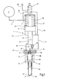
- FIG. 1 is a longitudinal section through a common rail injector 1 shown, which is supplied via an only schematically indicated pressure accumulator space 2 (common rail) with fuel under high pressure.
- a fuel supply line 3, 4 extends to a pressure booster 5, which is integrated into the fuel injector 1.
- the pressure booster 5 is enclosed by an injector housing (not shown).
- the injector housing includes an injector body and a nozzle body having a central guide bore. In the guide bore, a nozzle needle 10 is guided back and forth movable.
- the nozzle needle 10 has a tip 11, on which a sealing surface is formed, which cooperates with a sealing seat, which is formed on the nozzle body.
- a pressure chamber 15 is formed, which communicates via a connecting channel 18 with a pressure booster chamber 22 in connection.
- the pressure booster chamber 22 is supplied with high-pressure fuel, which is further compressed in response to the pressure in a pressure booster control chamber 23.
- one end 24 of a pressure booster piston 25 protrudes into the pressure booster chamber 22.
- the end 24 of the pressure booster piston 25 has substantially the shape of a circular cylinder whose outer diameter is smaller than the outer diameter of the section 25 of the pressure booster piston.
- a pressure booster spring 27 is arranged, by means of which the pressure booster piston 25 is biased in the direction of the nozzle needle 10 away.
- the pressure booster control chamber 23 communicates via a connecting channel 29 with a 3/2-way valve 32 in connection, which in turn communicates via a connecting channel 34 and the fuel supply lines 3,4 with the high-pressure accumulator chamber 2.
- the 3/2-way valve 32 has a port 35 to a fuel tank (not shown).
- the pressure booster control chamber 23 via the connection channels or connecting lines 29, 34, 3 and 4 with the high-pressure fuel storage chamber 2 in connection.
- the pressure booster chamber 22 communicates with the pressure booster control chamber 23.
- the check valve 40 has a check ball, which is biased for example by means of a check valve spring against a check valve seat that the pressure booster chamber 22 is filled via the connecting lines 41, 29, 34, 3 and 4 from the high-pressure fuel reservoir 2 with fuel when the Pressure in the booster chamber 22 is smaller than in the high-pressure fuel chamber 2.
- the pressure booster chamber 22 communicates via a connecting line 42 with a nozzle needle control chamber 44, which is also referred to as a damping chamber.
- the nozzle needle control chamber 44 is bounded at the top by a portion 45 of the injector.
- the Injektorgepurabites 45 has a central bore in which in a throttle piston 50, a first throttle 47, which is also referred to as a drain throttle, and a second throttle 48 are formed, which is also referred to as inlet throttle. Since both throttles, in particular the outlet throttle 47 with the smaller throttle cross-section, are flowed through or, when the pressure in the control chamber 41 decreases, the opening of the nozzle needle 10 takes place relatively slowly.
- the closing of the nozzle needle 10 is effected by a pressure increase in the nozzle needle control chamber 44.
- the pressure increase is caused by fuel flowing from the high-pressure fuel storage 2 via the supply lines 3, 4, the connecting channel 34, the pressure booster control chamber 23, the connecting channel 41, the connecting channel 42 and the inlet throttle 48 past the throttle body 61 in the nozzle needle control chamber 44.
- the nozzle needle control chamber 44 is bounded laterally by a sealing sleeve 56, which has a biting edge 57.
- the biting edge 57 opposite side of the sealing sleeve 56 is acted upon by a compression spring 58 which is biased between the sealing sleeve 56 and a collar 54 which is formed on the nozzle needle 10.
- the biasing force of the spring 58 causes the biting edge 57 of the sealing sleeve 56 to abut against the injector section 45.
- the biasing force of the spring 58 causes the tip 11 of the nozzle needle 10 to be pressed against its associated sealing seat.
- the combustion chamber facing away from the outer edge of the collar 51 on the throttle piston 50 forms a sealing edge 61 which is pressed by the prestressed compression spring 53 against an associated sealing seat, which is provided on the Injektorgepurabites 45.
- the Preload force of the compression spring 53 and the throttle cross section of the outlet throttle 47 are selected so that the throttle piston 50 lifts off with its sealing edge 61 of the associated seat on the Injektorgepurabites 45 when flows through the connecting line 42 and the inlet throttle 48 with high pressure fuel.
- the high-pressure fuel raises the throttle piston 50 from the sealing edge 61 and can then flow past the outlet throttle 47 into the nozzle needle control chamber 44. As a result, a fast closing of the nozzle needle 10 is ensured.
- the nozzle needle 10 is guided in the shaft, wherein flow channels 59, 60 are provided in the guide region, passes through the fuel from the pressure chamber 15 to the tip 11 of the nozzle needle 10.
- the pressure chamber 15, in which the nozzle closing spring 58 is arranged, is formed in the upper nozzle region.
- the pressure booster control chamber 23 is acted upon by the 3/2-way valve 32 with the same pressure as the pressure booster working chamber 26.
- the connection to the return line 35 is closed.
- the pressure booster piston 25 is pressure balanced and there is no pressure gain.
- the nozzle needle 10 is closed.
- the throttle piston 50 is in contact with the injector housing section 45 with the sealing edge 61.
- the pressure booster control chamber 23 is depressurized.
- the pressure booster control chamber 23 is decoupled from the high-pressure accumulator 2 with the aid of the 3/2-way valve 32 and is depressurized via the connecting line 29 into the return line 35.
- the pressure in the compression chamber 22 is thereby increased according to the transmission ratio of the pressure booster 5 and forwarded to the injection nozzle.
- the injector starts to open. Since the collar 51 of the throttle piston 50 rests against the injector housing section 45, ie the sealing seat is closed at 61, fuel must be displaced via the outlet throttle 47 and then via the inlet throttle 48 from the nozzle needle control chamber 44, which is also referred to as a damping chamber. This reduces the needle opening speed. By way of the flow rate of the outlet throttle 47, the needle opening speed can thus be set.
- the first throttle 47 is formed in a central bore of a throttle piston 50, which has a collar 51.
- the collar 51 of the throttle piston 50 is biased by a compression spring 53 against the tip 11 opposite end of the nozzle needle 10.
- the pressure in the nozzle needle control chamber 44 serves to control the injection of fuel through the injection holes 12, 13.
- the outlet throttle 47 has a smaller throttle cross-section than the inlet throttle 48. If the 3/2-way valve from the in FIG. 1 shown position is switched to its second (not shown) position, then the nozzle needle control chamber 44 via the connecting lines 42, 41, 29 and 35 in the (not shown) fuel tank emptied or relieved. When emptying or relieving the nozzle needle control chamber 44, both the first throttle 47 and the second throttle 48 are flowed through. Due to the pressure drop in the nozzle needle control chamber 44, the nozzle needle 10 lifts with its tip 11 from the associated sealing seat.
- the pressure booster 5 remains activated and compresses the fuel in the booster chamber 22, which can also be referred to as a compression chamber.
- the compressed fuel is forwarded to the nozzle needle 10 and injected.
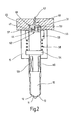
- the throttle piston 50 is also designed as a stroke stop for the nozzle needle 10.
- the stroke stop of the nozzle needle 10 is adjustable over the height or length of the throttle piston 50, whereby a high accuracy of the Nadelhubs is achieved in the production of the injector.
- the stroke stop of the nozzle needle 10 may be formed so that the sealing seat at 61 and another sealing seat at 62 are closed when the combustion chamber distal end of the nozzle needle 10 comes to rest on the throttle piston 50.
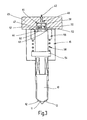
- the throttle piston 50 is formed shorter than that in the FIGS. 1 and 2 illustrated embodiment.
- FIG. 3 forms the throttle piston 50 no stroke stop for the nozzle needle 10.
- the nozzle needle 10 comes in the in FIG. 3 illustrated embodiment in its upper stroke stop with its combustion chamber remote end 62 to a sealing edge 63 for conditioning, which is formed on the Injektorgepuruseabites 45. This prevents that after needle opening, the pressure on the inside of the sealing sleeve 56 drops too much, so that an undesirably large deformation of the sealing sleeve 56 is prevented.
- an overshoot of the pressure in the chambers 23 and 44 via system pressure and undershooting in the chamber 15 under system pressure can be achieved for a short time in the needle closing phase.
- a higher pressure than in the pressure chamber 15, which is also referred to as an intermediate space In this case, the sealing sleeve 56 can be released from the contact point on the throttle piston 50 and the closing pressure in the nozzle needle control chamber 44 breaks. Due to the closing spring force on the nozzle needle 10, however, this continues its closing movement. This opening of the sealing sleeve 56 can be used to achieve a flushing of the nozzle needle control chamber 44.
- the pressure booster piston 25 is returned to its initial position by the booster spring 27, which may also be referred to as a return spring.
- the pressure booster chamber 22 is filled via the check valve 40.
- the throttle piston 50 is by the compression spring 53 in its closed rest position reset.
- the connecting line 41 which may be designed, for example, as a control bore, may alternatively also be connected to the region of the pressure booster working space 26 / high-pressure reservoir 2.
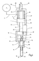
- FIG. 4 is a similar fuel injector as in FIG. 1 shown.
- the same reference numerals are used to designate like parts. To avoid repetition, the preceding description of the FIG. 1 directed. In the following, only the differences between the two embodiments will be discussed.
- FIG. 4 shows an embodiment with two separately formed throttle paths 71 and 73 in the nozzle needle control chamber 44.
- a discharge throttle 72 is provided in the throttle path 71.
- a check valve 74 and an inlet throttle 75 are provided in the throttle path 73. Due to the separately formed throttle paths 71 and 73, the volume of the nozzle needle control chamber 44 can be kept very small, whereby a vibration-reduced needle opening can be achieved.
- the nozzle needle control chamber 44 is connected via the throttle 72 to the control line 41.
- the nozzle needle control chamber 44 is connected to the control line 41 via the throttle 75 and the check valve 74.
- the needle opening speed is determined by the drain throttle 72.
- the needle closing speed can be adjusted via the inlet throttle 75.
- FIG. 5 is a similar fuel injector as in FIG. 4 shown.
- the same reference numerals are used to designate like parts. To avoid repetition, the preceding description of the FIG. 4 directed. In the following, only the differences between the two embodiments will be discussed.
- FIG. 5 illustrated embodiment another design of the nozzle needle 10 is used.
- the two inlet paths 71 and 73 which can also be referred to as throttle paths, open into a nozzle needle control chamber 80, in which a nozzle needle spring 81 is arranged.
- a nozzle needle spring 81 By the biasing force of the nozzle needle spring 81, the nozzle needle 10 is held with its tip 11 against the associated sealing seat in abutment.
- a pressure shoulder 83 is formed, which is arranged in a substantially annular pressure chamber 84.
- the pressure chamber 84 is connected via a connecting line 86 to the pressure booster chamber 22 in connection.
Claims (13)
- Dispositif d'injection de carburant dans une chambre de combustion d'un moteur à combustion interne, comprenant une soupape de dosage (32) et un injecteur de carburant (1), qui peut être sollicité par le biais d'une source haute pression (2) avec du carburant à haute pression et qui peut être actionné par la soupape de dosage (32), l'activation de la soupape de dosage (32) provoquant la réduction de la pression dans une première conduite de commande (29) de sorte qu'un accumulateur de pression (5) soit activé, en ce qu'un espace de commande de l'accumulateur de pression (23) est détendu en pression par le biais de la première conduite de commande (29) par le biais d'un retour (35), la pression dans un espace de commande d'aiguille de buse (44) pouvant être commandée par le biais de la soupape de dosage (32) de telle sorte qu'une aiguille de buse (10) pour l'injection de carburant s'ouvre et se ferme, l'espace de commande d'aiguille de buse (44) pouvant être vidangé par le biais d'un dispositif d'étranglement de sortie (47, 72) et pouvant être rempli par le biais d'un dispositif d'étranglement d'amenée (48, 75), et l'espace de commande d'accumulateur de pression (23) et l'espace de commande d'aiguille de buse (44) étant connectés par le biais d'une liaison hydraulique, caractérisé en ce que la liaison hydraulique entre l'espace de commande d'accumulateur de pression (23) et l'espace de commande d'aiguille de buse (44) contient une deuxième conduite de commande (41), en ce que l'espace de commande d'aiguille de buse (44) peut être vidangé par le biais du dispositif d'étranglement de sortie dans la deuxième conduite de commande (41) et peut être rempli par le biais du dispositif d'étranglement d'amenée hors de la deuxième conduite de commande (41), et en ce que la section transversale d'étranglement du dispositif d'étranglement de sortie (47, 72) est inférieure à la section transversale d'étranglement du dispositif d'étranglement d'amenée (48, 75).
- Dispositif d'injection de carburant selon la revendication 1, caractérisé en ce qu'il est prévu un élément de soupape (74) qui est fermé lorsque l'espace de commande d'organe de soupape d'injection (44) est vidangé et qui est ouvert lorsque l'espace de commande d'organe de soupape d'injection (44) est rempli.
- Dispositif d'injection de carburant selon l'une quelconque des revendications précédentes, caractérisé en ce que le dispositif d'étranglement de sortie ne produit son effet d'étranglement que lors de la vidange de l'espace de commande d'organe de soupape d'injection (44) et ne produit aucun effet d'étranglement lors du remplissage de l'espace de commande d'organe de soupape d'injection (44), mais garantit un passage de carburant sans obstruction.
- Dispositif d'injection de carburant selon la revendication 3, caractérisé en ce que les deux dispositifs d'étranglement sont montés en série.
- Dispositif d'injection de carburant selon la revendication 3 ou 4, caractérisé en ce que les deux dispositifs d'étranglement sont disposés centralement par rapport à l'axe longitudinal de l'injecteur de carburant (1).
- Dispositif d'injection de carburant selon l'une quelconque des revendications 3 à 5, caractérisé en ce que le dispositif d'étranglement de sortie comprend un élément d'étranglement (50) avec une arête d'étanchéité (61), qui est précontraint par un élément de ressort (53) de telle sorte que l'arête d'étanchéité (61) soit pressée contre un siège d'étanchéité associé, lorsque l'élément d'étranglement (50) est parcouru par l'écoulement dans la direction de vidange et de telle sorte que l'arête d'étanchéité (61) se soulève de son siège d'étanchéité lorsque l'élément d'étranglement (50) est parcouru par l'écoulement dans la direction de remplissage.
- Dispositif d'injection de carburant selon la revendication 6, caractérisé en ce que l'élément d'étranglement (50) comprend un piston d'étranglement précontraint par l'élément de ressort (53) et muni d'un trou traversant présentant un point d'étranglement, dont l'extrémité libre forme une butée de levée pour l'aiguille de buse (10).
- Dispositif d'injection de carburant selon la revendication 7, caractérisé en ce que la butée de levée (62) de l'aiguille de buse (10) est réalisée de telle sorte qu'un siège d'étanchéité (61) et un autre siège d'étanchéité (62) soient fermés, lorsque l'extrémité, éloignée de la chambre de combustion, de l'aiguille de buse (10) vient en appui contre le piston d'étranglement (50).
- Dispositif d'injection de carburant selon l'une quelconque des revendications 1 à 6, caractérisé en ce que l'aiguille de buse (10) dans sa butée de levée supérieure vient en appui avec son extrémité (62) éloignée de la chambre de combustion contre une arête d'étanchéité (63) qui est réalisée sur une portion de boîtier d'injecteur (45).
- Dispositif d'injection de carburant selon l'une quelconque des revendications 1 à 3, caractérisé en ce que les deux dispositifs d'étranglement sont montés en parallèle.
- Dispositif d'injection de carburant selon la revendication 10, caractérisé en ce que le dispositif d'étranglement d'amenée comprend un élément d'étranglement (75) qui est monté en série avec une soupape de non retour de telle sorte que l'élément d'étranglement (75) ne soit parcouru par l'écoulement que dans la direction de remplissage et soit fermé dans la direction de vidange.
- Dispositif d'injection de carburant selon la revendication 10 ou 11, caractérisé en ce que le dispositif d'étranglement d'amenée est disposé de manière décentrée par rapport à l'axe longitudinal de l'injecteur de carburant (1).
- Dispositif d'injection de carburant selon l'une quelconque des revendications 10 à 12, caractérisé en ce que le dispositif d'étranglement de sortie est disposé centralement par rapport à l'axe longitudinal de l'injecteur de carburant (1).
Applications Claiming Priority (2)
| Application Number | Priority Date | Filing Date | Title |
|---|---|---|---|
| DE102004024527A DE102004024527A1 (de) | 2004-05-18 | 2004-05-18 | Kraftstoffeinspritzeinrichtung |
| DE102004024527 | 2004-05-18 |
Publications (2)
| Publication Number | Publication Date |
|---|---|
| EP1598551A1 EP1598551A1 (fr) | 2005-11-23 |
| EP1598551B1 true EP1598551B1 (fr) | 2011-08-24 |
Family
ID=34938875
Family Applications (1)
| Application Number | Title | Priority Date | Filing Date |
|---|---|---|---|
| EP05101652A Expired - Fee Related EP1598551B1 (fr) | 2004-05-18 | 2005-03-03 | Dispositif d'injection de carburant |
Country Status (3)
| Country | Link |
|---|---|
| US (1) | US20050263135A1 (fr) |
| EP (1) | EP1598551B1 (fr) |
| DE (1) | DE102004024527A1 (fr) |
Families Citing this family (14)
| Publication number | Priority date | Publication date | Assignee | Title |
|---|---|---|---|---|
| DE102004017305A1 (de) * | 2004-04-08 | 2005-10-27 | Robert Bosch Gmbh | Kraftstoffeinspritzeinrichtung für Brennkraftmaschinen mit direkt ansteuerbaren Düsennadeln |
| DE102004053274A1 (de) * | 2004-11-04 | 2006-05-11 | Robert Bosch Gmbh | Kraftstoffeinspritzeinrichtung |
| DE102005030220A1 (de) * | 2005-06-29 | 2007-01-04 | Robert Bosch Gmbh | Injektor mit zuschaltbarem Druckübersetzer |
| DE102005058556B4 (de) * | 2005-12-08 | 2017-04-06 | Man Diesel & Turbo Se | Injektor eines Kraftstoffeinspritzsystems |
| JP4519143B2 (ja) * | 2007-01-19 | 2010-08-04 | 株式会社デンソー | インジェクタ |
| US9163597B2 (en) * | 2008-10-01 | 2015-10-20 | Caterpillar Inc. | High-pressure containment sleeve for nozzle assembly and fuel injector using same |
| DE102009000181A1 (de) * | 2009-01-13 | 2010-07-15 | Robert Bosch Gmbh | Kraftstoff-Injektor |
| DE102010001170A1 (de) * | 2010-01-25 | 2011-07-28 | Robert Bosch GmbH, 70469 | Einspritzvorrichtung mit reduzierten Druckschwingungen |
| CN104956064B (zh) | 2012-10-25 | 2019-02-19 | 比克喷射有限公司 | 燃料喷射系统 |
| DE102013212269A1 (de) * | 2013-06-26 | 2014-12-31 | Robert Bosch Gmbh | Kraftstoffeinspritzventil für Brennkraftmaschinen |
| EP3455498A4 (fr) | 2016-05-12 | 2020-01-01 | Briggs & Stratton Corporation | Injecteur de distribution de carburant |
| WO2018022754A1 (fr) | 2016-07-27 | 2018-02-01 | Picospray, Llc | Injecteur à pompe à mouvement alternatif |
| US10947940B2 (en) | 2017-03-28 | 2021-03-16 | Briggs & Stratton, Llc | Fuel delivery system |
| US11668270B2 (en) | 2018-10-12 | 2023-06-06 | Briggs & Stratton, Llc | Electronic fuel injection module |
Family Cites Families (17)
| Publication number | Priority date | Publication date | Assignee | Title |
|---|---|---|---|---|
| JP2885076B2 (ja) * | 1994-07-08 | 1999-04-19 | 三菱自動車工業株式会社 | 蓄圧式燃料噴射装置 |
| GB9614822D0 (en) * | 1996-07-13 | 1996-09-04 | Lucas Ind Plc | Injector |
| IT1289795B1 (it) * | 1996-12-23 | 1998-10-16 | Elasis Sistema Ricerca Fiat | Perfezionamenti ad una valvola di dosaggio a comando elettromagnetico, con otturatore a sfera, per un iniettore di combustibile. |
| DE19822503C1 (de) * | 1998-05-19 | 1999-11-25 | Siemens Ag | Steuerventil für Kraftstoffeinspritzventil |
| US6293254B1 (en) * | 2000-01-07 | 2001-09-25 | Cummins Engine Company, Inc. | Fuel injector with floating sleeve control chamber |
| DE10123775B4 (de) * | 2001-05-16 | 2005-01-20 | Robert Bosch Gmbh | Kraftstoff-Einspritzvorrichtung für Brennkraftmaschinen, insbesondere Common-Rail-Injektor, sowie Kraftstoffsystem und Brennkraftmaschine |
| DE10218904A1 (de) * | 2001-05-17 | 2002-12-05 | Bosch Gmbh Robert | Kraftstoffeinspritzeinrichtung |
| EP1395748B1 (fr) * | 2001-05-21 | 2005-05-18 | Robert Bosch Gmbh | Element d'etancheite haute pression pour injecteurs |
| DE10158951A1 (de) * | 2001-12-03 | 2003-06-12 | Daimler Chrysler Ag | Mit Druckübersetzung arbeitendes Einspritzsystem |
| DE10160263A1 (de) * | 2001-12-07 | 2003-06-18 | Bosch Gmbh Robert | Kraftstoffeinspritzeinrichtung für eine Brennkraftmaschine |
| DE10229419A1 (de) * | 2002-06-29 | 2004-01-29 | Robert Bosch Gmbh | Druckübersetzter Kraftstoffinjektor mit schnellem Druckabbau bei Einspritzende |
| GB0215490D0 (en) * | 2002-07-04 | 2002-08-14 | Delphi Tech Inc | Control valve arrangement |
| JP4007103B2 (ja) * | 2002-07-11 | 2007-11-14 | 株式会社豊田中央研究所 | 燃料噴射装置 |
| SE523110C2 (sv) | 2002-07-15 | 2004-03-30 | Stock Of Sweden Ab | Hydraulsystem |
| DE10300045A1 (de) * | 2003-01-03 | 2004-07-15 | Robert Bosch Gmbh | Nach innen öffnende Variodüse |
| DE10335211A1 (de) * | 2003-08-01 | 2005-02-17 | Robert Bosch Gmbh | Kraftstoff-Einspritzvorrichtung für eine Brennkraftmaschine |
| DE10346222A1 (de) * | 2003-09-23 | 2005-04-14 | Robert Bosch Gmbh | Kraftstoff-Einspritzvorrichtung, insbesondere für eine Brennkraftmaschine mit Kraftstoff-Direkteinspritzung |
-
2004
- 2004-05-18 DE DE102004024527A patent/DE102004024527A1/de not_active Withdrawn
-
2005
- 2005-03-03 EP EP05101652A patent/EP1598551B1/fr not_active Expired - Fee Related
- 2005-05-18 US US11/131,469 patent/US20050263135A1/en not_active Abandoned
Also Published As
| Publication number | Publication date |
|---|---|
| US20050263135A1 (en) | 2005-12-01 |
| EP1598551A1 (fr) | 2005-11-23 |
| DE102004024527A1 (de) | 2005-12-15 |
Similar Documents
| Publication | Publication Date | Title |
|---|---|---|
| EP1598551B1 (fr) | Dispositif d'injection de carburant | |
| EP1771651B1 (fr) | Injecteur de carburant a commande polyetagee directe de l'element de soupape d'injection | |
| EP1636484B1 (fr) | Injecteur pour moteurs a combustion interne | |
| EP1654456B1 (fr) | Dispositif d'injection de carburant pour moteur a combustion interne | |
| DE19742320A1 (de) | Kraftstoffeinspritzventil | |
| EP1657428B1 (fr) | Dispositif d'injection de carburant | |
| WO2005019637A1 (fr) | Soupape d'injection de carburant commandee par une soupape pilote | |
| DE10336327A1 (de) | Injektor für Kraftstoff-Einspritzsysteme von Brennkraftmaschinen, insbesondere von direkteinspritzenden Dieselmotoren | |
| EP1520100B1 (fr) | Dispositif permettant d'amortir la course de l'aiguille sur des injecteurs de carburant commandes par pression | |
| DE19919432C2 (de) | Common Rail Injektor | |
| DE102009000181A1 (de) | Kraftstoff-Injektor | |
| EP1117921B1 (fr) | Injecteur de carburant pour un système carburant à rampe commune | |
| DE19939939A1 (de) | Injektor für ein Common-Rail-Einspritzsystem für Brennkraftmaschinen mit kompakter Bauweise | |
| EP2743493A2 (fr) | Injecteur de carburant | |
| EP2156045B1 (fr) | Injecteur | |
| EP1719904A1 (fr) | Injecteur de carburant | |
| DE60111164T2 (de) | Brennstoffeinspritzventil mit piezoelektrischem Aktor | |
| WO2004022929A1 (fr) | Actionneur hydraulique de soupape servant a actionner une soupape d'echange de gaz | |
| WO2005014997A1 (fr) | Dispositif d'injection de carburant pour moteur a combustion interne | |
| EP2275666A1 (fr) | Injecteur de carburant doté d'une soupape de distribution à pression compensée | |
| DE3009750A1 (de) | Brennstoffeinspritzvorrichtung fuer brennkraftmaschinen | |
| DE10147830B4 (de) | Kraftstoffinjektor | |
| DE102007034319A1 (de) | Injektor | |
| EP1377745B1 (fr) | Procede pour actionner une unite pompe-ajutage et unite pompe-ajutage correspondante | |
| DE10160490B4 (de) | Kraftstoff-Einspritzvorrichtung, Kraftstoffsystem sowie Brennkraftmaschine |
Legal Events
| Date | Code | Title | Description |
|---|---|---|---|
| PUAI | Public reference made under article 153(3) epc to a published international application that has entered the european phase |
Free format text: ORIGINAL CODE: 0009012 |
|
| AK | Designated contracting states |
Kind code of ref document: A1 Designated state(s): AT BE BG CH CY CZ DE DK EE ES FI FR GB GR HU IE IS IT LI LT LU MC NL PL PT RO SE SI SK TR |
|
| AX | Request for extension of the european patent |
Extension state: AL BA HR LV MK YU |
|
| 17P | Request for examination filed |
Effective date: 20060523 |
|
| AKX | Designation fees paid |
Designated state(s): DE ES FR IT |
|
| 17Q | First examination report despatched |
Effective date: 20080919 |
|
| GRAP | Despatch of communication of intention to grant a patent |
Free format text: ORIGINAL CODE: EPIDOSNIGR1 |
|
| GRAS | Grant fee paid |
Free format text: ORIGINAL CODE: EPIDOSNIGR3 |
|
| GRAA | (expected) grant |
Free format text: ORIGINAL CODE: 0009210 |
|
| AK | Designated contracting states |
Kind code of ref document: B1 Designated state(s): DE ES FR IT |
|
| REG | Reference to a national code |
Ref country code: DE Ref legal event code: R096 Ref document number: 502005011802 Country of ref document: DE Effective date: 20111020 |
|
| PLBE | No opposition filed within time limit |
Free format text: ORIGINAL CODE: 0009261 |
|
| STAA | Information on the status of an ep patent application or granted ep patent |
Free format text: STATUS: NO OPPOSITION FILED WITHIN TIME LIMIT |
|
| 26N | No opposition filed |
Effective date: 20120525 |
|
| REG | Reference to a national code |
Ref country code: DE Ref legal event code: R097 Ref document number: 502005011802 Country of ref document: DE Effective date: 20120525 |
|
| PG25 | Lapsed in a contracting state [announced via postgrant information from national office to epo] |
Ref country code: ES Free format text: LAPSE BECAUSE OF FAILURE TO SUBMIT A TRANSLATION OF THE DESCRIPTION OR TO PAY THE FEE WITHIN THE PRESCRIBED TIME-LIMIT Effective date: 20111205 |
|
| REG | Reference to a national code |
Ref country code: FR Ref legal event code: PLFP Year of fee payment: 11 |
|
| PGFP | Annual fee paid to national office [announced via postgrant information from national office to epo] |
Ref country code: IT Payment date: 20150324 Year of fee payment: 11 |
|
| PGFP | Annual fee paid to national office [announced via postgrant information from national office to epo] |
Ref country code: FR Payment date: 20150319 Year of fee payment: 11 |
|
| REG | Reference to a national code |
Ref country code: FR Ref legal event code: ST Effective date: 20161130 |
|
| PG25 | Lapsed in a contracting state [announced via postgrant information from national office to epo] |
Ref country code: FR Free format text: LAPSE BECAUSE OF NON-PAYMENT OF DUE FEES Effective date: 20160331 |
|
| PG25 | Lapsed in a contracting state [announced via postgrant information from national office to epo] |
Ref country code: IT Free format text: LAPSE BECAUSE OF NON-PAYMENT OF DUE FEES Effective date: 20160303 |
|
| PGFP | Annual fee paid to national office [announced via postgrant information from national office to epo] |
Ref country code: DE Payment date: 20170529 Year of fee payment: 13 |
|
| REG | Reference to a national code |
Ref country code: DE Ref legal event code: R119 Ref document number: 502005011802 Country of ref document: DE |
|
| PG25 | Lapsed in a contracting state [announced via postgrant information from national office to epo] |
Ref country code: DE Free format text: LAPSE BECAUSE OF NON-PAYMENT OF DUE FEES Effective date: 20181002 |