EP1598213A2 - Feststellbarer Schnellverstellzirkel - Google Patents
Feststellbarer Schnellverstellzirkel Download PDFInfo
- Publication number
- EP1598213A2 EP1598213A2 EP05010057A EP05010057A EP1598213A2 EP 1598213 A2 EP1598213 A2 EP 1598213A2 EP 05010057 A EP05010057 A EP 05010057A EP 05010057 A EP05010057 A EP 05010057A EP 1598213 A2 EP1598213 A2 EP 1598213A2
- Authority
- EP
- European Patent Office
- Prior art keywords
- threaded
- adjusting spindle
- compass
- schnellverstellzirkel
- thread
- Prior art date
- Legal status (The legal status is an assumption and is not a legal conclusion. Google has not performed a legal analysis and makes no representation as to the accuracy of the status listed.)
- Granted
Links
Images

Classifications
-
- B—PERFORMING OPERATIONS; TRANSPORTING
- B43—WRITING OR DRAWING IMPLEMENTS; BUREAU ACCESSORIES
- B43L—ARTICLES FOR WRITING OR DRAWING UPON; WRITING OR DRAWING AIDS; ACCESSORIES FOR WRITING OR DRAWING
- B43L9/00—Circular curve-drawing or like instruments
- B43L9/16—Features common to compasses, dividers, and callipers
- B43L9/22—Leg-angle adjusting-means separate from pivots
Definitions
- the invention relates to a Schnellverstellzirkel with one of the compass legs in therein threaded sleeves passing through running threaded adjusting spindle with a centrally arranged, non-rotatable with the adjusting spindle connected adjusting wheel, wherein the adjusting spindle by means of the compass legs at least partially enforcing locking screws in the threaded sleeves is blockable.
- a conventional, not quickly adjustable compass is characterized by that between the adjusting spindle and the mounted in the threaded sleeve Female thread when pressure against the thighs a self-locking occurs.
- the invention is therefore based on the object, a Schnellverstellzirkel the the type mentioned above in such a way that with a simple structure a complete play-free blocking of the adjusting spindle in any pivot position the quick-release compass is possible.
- the invention provides that through the Locking screw, the adjusting spindle with its thread directly to a blocking member can be pressed.
- a first embodiment of this solution according to the invention in which not the Threaded sleeve is tightened for detecting the adjusting spindle, looks at this Purpose before that the threaded sleeve in a direction perpendicular to the axis of the threaded rod continuous recess of the compass leg slidably mounted Bolt with cross threaded holes for the threaded rod is by a on an end male threaded portion screwed threaded nut below Bracing the threaded rod on the inner wall of the enforced by her Transverse breakthrough of the compass leg is adjustable.
- the Blocking pin may preferably be formed of plastic, so that damage the thread of the adjusting spindle can not take place leads in particular easy way to an exact play-free blocking of the adjustment.
- the locking pin of the set screw of the locking screw is that in a cross threaded hole of the threaded sleeve or the circular leg is screwed or that the threaded sleeve in a perpendicular to the Axle of the threaded rod through recess of the compass leg mounted
- Bolt with hollow shaft is on one side with a head on Gimbal legs supported, on the other protruding, with an external thread provided end, a cap nut under displacement of the locking pin in the inner bore of the shaft can be screwed.
- the training is similar in this second variant of the solution with the compass legs jammed adjusting spindle, although here the adjusting spindle is not blocked by jamming to the compass legs but by the slidable in the hollow bolt of the threaded sleeve over the locking cap nut Blocking pin.
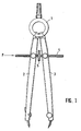
- Fig. 1 can be seen a Schnellverstellzirkel with two on a headboard. 1 pivotally mounted compass legs 2 and 3, by a threaded adjusting spindle 4 are traversed with adjusting 5, wherein the threaded adjusting spindle in enforced in different ways, shown in Fig. 2 threaded sleeves 6 interspersed, the openings extending transversely to the axis of the threaded adjusting spindle the compass legs 2, 3 are stored. A shown in Fig. 2 large Breakthrough 7 allows each strong transverse displacement between compass legs and threaded adjusting spindle.
- each of the compass legs 2, 3 locking devices Although it is sufficient for the operation of course would be if only one of the legs with such a locking device would be provided.
- the simplest form of blocking the threaded adjusting spindle and thus the determination of Schnellverstellzirkels in a desired Pivoting position is shown in Fig. 2.
- the threaded sleeve 6 forms there in the mounted perpendicular to the axis of the adjusting spindle through recess 8 Bolt with a threaded hole 9 for the adjusting spindle into which a cross threaded hole 10 opens, in which a locking screw 11 is screwed.
- the shaft 12 of this locking screw engages when screwing directly to the external thread the adjusting 4 and blocks them and thus the compass in the desired position.
- FIG. 3 shows a modification which differs from that of FIG. 2 only by that it is at the locking screw 11 'to a plastic screw acts, which has the advantage that when blocking the most metallic threaded spindle 4 whose external thread is not through the locking screw is pressed, as in the metallic locking screw 11 of FIG. 2 of Case could be.
- FIG. 4 In the arrangement of FIG. 4 is the threaded sleeve 6 'for the threaded adjusting spindle forming bolts in the same way in the compass leg 2 (and optionally Also 3) stored, with the bolt on the right side with an external thread 13 is provided, on which a cap nut 14 with internal thread screwed is, as soon as this cap nut 14 on the side 15 of the compass leg As it continues to rotate, it pulls the bolt to the right and thus presses the bolt Thread adjusting spindle 4 to the inside 16 of the opening 7, so in turn a blockage of the adjusting spindle 4 is achieved.
Landscapes
- Pivots And Pivotal Connections (AREA)
- Prostheses (AREA)
Abstract
Description
- Fig. 1
- eine Ansicht eines Schnellverstellzirkels mit durch Feststellschrauben blockierbarer Gewindeverstellspindel, und
- Fig. 2 bis 5
- vergrößerte teilweise aufgeschnittene Teilseitenansichten des Zirkelschenkels in Höhe der Gewindeverstellspindel in Richtung des Pfeils P in Fig. 1.
Claims (6)
- Schnellverstellzirkel mit einer die Zirkelschenkel (2, 3) in darin gelagerten Gewindehülsen (6) durchsetzenden mitlaufenden Gewinde-Verstellspindel (4), mit einem mittig angeordneten, drehfest mit der Verstellspindel (4) verbundenen Verstellrad (5), wobei die Verstellspindel (4) mittels die Zirkelschenkel (2, 3) zumindest teilweise durchsetzender Feststellschrauben (11) in den Gewindehülsen (6) blockierbar ist, dadurch gekennzeichnet, dass durch die Feststellschraube (11, 11', 14) die Verstellspindel (4) mit ihrem Gewinde direkt an ein Blockierglied (12, 16, 18) anpressbar ist.
- Schnellverstellzirkel nach Anspruch 1, dadurch gekennzeichnet, dass die Gewindehülse (6, 6', 6") ein in einer senkrecht zur Achse der Verstellspindel (4) durchgehenden Ausnehmung (8) des Zirkelschenkels (2, 3) verschiebbar gelagerter Bolzen mit Quergewindebohrungen (9) für die Gewindestange (4) ist, der durch eine auf einen endseitigen Außengewindeabschnitt (13) aufschraubbare Gewindemutter (14) unter Verspannen der Gewindestange (4) an der Innenwand (16) des von ihr durchsetzten Querdurchbruchs (7) des Zirkelschenkels (2, 3) verstellbar ist.
- Schnellverstellzirkel nach Anspruch 1, dadurch gekennzeichnet, dass die Feststellschraube einen die Gewindehülse quer zur Gewindebohrung (9) für die Verstellspindel (4) durchsetzenden Blockierstift (12, 18) in das Gewinde der Verstellspindel (4) drückt.
- Schnellverstellzirkel nach Anspruch 3, dadurch gekennzeichnet, dass der Blockierstift der Gewindestift (12) der Feststellschraube (11) ist, die in eine Quergewindebohrung (10) der Gewindehülse (6) einschraubbar ist.
- Schnellverstellzirkel nach Anspruch 3, dadurch gekennzeichnet, dass die Gewindehülse (6") ein in einer senkrecht zur Achse der Verstellspindel (4) durchgehenden Ausnehmung (8) des Zirkelschenkels (2, 3) gelagerter Bolzen mit hohlem Schaft ist, der auf einer Seite sich gegebenenfalls mit einem Kopf (17) am Zirkelschenkel (2, 3) abstützt und auf dessen herausstehenden anderen, mit einem Außengewinde (13) versehenen Ende eine Hutmutter (14) unter Verschiebung des Blockierstifts (18) in der Innenbohrung (19) des Schaftes aufschraubbar ist.
- Schnellverstellzirkel nach einem der Ansprüche 3 bis 5, dadurch gekennzeichnet, dass der Blockierstift (18) aus Kunststoff besteht.
Applications Claiming Priority (2)
| Application Number | Priority Date | Filing Date | Title |
|---|---|---|---|
| DE102004024945 | 2004-05-21 | ||
| DE200410024945 DE102004024945B4 (de) | 2004-05-21 | 2004-05-21 | Feststellbarer Schnellverstellzirkel |
Publications (3)
| Publication Number | Publication Date |
|---|---|
| EP1598213A2 true EP1598213A2 (de) | 2005-11-23 |
| EP1598213A3 EP1598213A3 (de) | 2009-09-02 |
| EP1598213B1 EP1598213B1 (de) | 2015-07-01 |
Family
ID=34936298
Family Applications (1)
| Application Number | Title | Priority Date | Filing Date |
|---|---|---|---|
| EP05010057.7A Expired - Lifetime EP1598213B1 (de) | 2004-05-21 | 2005-05-09 | Feststellbarer Schnellverstellzirkel |
Country Status (2)
| Country | Link |
|---|---|
| EP (1) | EP1598213B1 (de) |
| DE (1) | DE102004024945B4 (de) |
Cited By (1)
| Publication number | Priority date | Publication date | Assignee | Title |
|---|---|---|---|---|
| WO2012035562A3 (en) * | 2010-09-18 | 2012-06-07 | Chetan Jayendra Budh | Locking mechanism for drawing compass |
Citations (2)
| Publication number | Priority date | Publication date | Assignee | Title |
|---|---|---|---|---|
| GB722242A (en) | 1952-11-12 | 1955-01-19 | Thornton Ltd Ag | Improvements in or relating to mathematical drawing instruments |
| DE1761101B1 (de) | 1968-04-03 | 1970-05-21 | Guenther Partes Kg Reisszeugfa | Zirkel mit Schnell- und Feineinstellung der Schenkel |
Family Cites Families (5)
| Publication number | Priority date | Publication date | Assignee | Title |
|---|---|---|---|---|
| DE176441C (de) * | ||||
| US2567733A (en) * | 1948-06-11 | 1951-09-11 | George A Ryan | Drawing compass attachment |
| DE7703293U1 (de) * | 1977-02-04 | 1977-06-30 | Clemens Riefler, Fabrik Mathematischer Instrumente Nesselwang, Kg, 8964 Nesselwang | Schnellverstellzirkel mit Doppelhebelbetätigung |
| DE3007571A1 (de) * | 1980-02-28 | 1981-09-10 | Intercompass Import u. Export-Gesellschaft mbH, 8531 Wilhelmsdorf | Schnellverstellzirkel |
| DE3807035A1 (de) * | 1988-03-04 | 1989-09-14 | Klaus Juergen Kiefer | Messzirkel |
-
2004
- 2004-05-21 DE DE200410024945 patent/DE102004024945B4/de not_active Expired - Fee Related
-
2005
- 2005-05-09 EP EP05010057.7A patent/EP1598213B1/de not_active Expired - Lifetime
Patent Citations (2)
| Publication number | Priority date | Publication date | Assignee | Title |
|---|---|---|---|---|
| GB722242A (en) | 1952-11-12 | 1955-01-19 | Thornton Ltd Ag | Improvements in or relating to mathematical drawing instruments |
| DE1761101B1 (de) | 1968-04-03 | 1970-05-21 | Guenther Partes Kg Reisszeugfa | Zirkel mit Schnell- und Feineinstellung der Schenkel |
Cited By (1)
| Publication number | Priority date | Publication date | Assignee | Title |
|---|---|---|---|---|
| WO2012035562A3 (en) * | 2010-09-18 | 2012-06-07 | Chetan Jayendra Budh | Locking mechanism for drawing compass |
Also Published As
| Publication number | Publication date |
|---|---|
| EP1598213A3 (de) | 2009-09-02 |
| DE102004024945B4 (de) | 2006-05-04 |
| EP1598213B1 (de) | 2015-07-01 |
| DE102004024945A1 (de) | 2005-12-15 |
Similar Documents
| Publication | Publication Date | Title |
|---|---|---|
| DE3610284C2 (de) | ||
| EP0259618B1 (de) | Während und nach der Montage verstellbares Tür- und Fensterband | |
| DE102015003439B3 (de) | Tür- oder Fensterscharnier | |
| EP0886071A1 (de) | Schraubeinheit | |
| DE202010016197U1 (de) | Spielfrei laufendes Zahnrad | |
| DE102012105575B4 (de) | Lagerungseinheit | |
| DE102020101057B3 (de) | Aufbau eines Drehmomentschlüssels | |
| DE8908545U1 (de) | Befestigungselement, insbesondere für eine Kugel-Gewindespindel | |
| EP1588975A2 (de) | Abhängeelement | |
| EP0421281A1 (de) | Vorrichtung zur Verstellung der Spurweite eines Fahrzeuges, insbesondere eines Ackerschleppers | |
| EP3929458B1 (de) | Selbstsichernder vorspannring für federbeine | |
| DE4431286C2 (de) | Linearführung | |
| EP3150786A1 (de) | Gelenkverbindung | |
| DE102015012641B3 (de) | Gelenkverbindung | |
| EP0875439A2 (de) | Spann- und Klemmvorrichtung | |
| DE4224697C1 (de) | Knotenpunktverbindung bei ebenen oder räumlichen Fachwerken aus Stäben und Knotenstücken | |
| EP1598213B1 (de) | Feststellbarer Schnellverstellzirkel | |
| DE4026651A1 (de) | Schneidkopf sowie ein damit ausgestattetes fraeswerkzeug | |
| DE10236031C1 (de) | Scharnierband mit einer höheneinstellbaren Hebe-Senkvorrichtung für Türen oder Fenster | |
| DE2816908A1 (de) | Achsbolzenverbindung | |
| DE2738522C3 (de) | Druckmittelbetriebener Arbeitszylinder | |
| DE19840328C1 (de) | Prüferstange | |
| DE202006003010U1 (de) | Fahrradgabel mit Verriegelungsmechanismus | |
| WO1995014148A1 (de) | Tür- oder fensterband | |
| EP2562460B1 (de) | Einstellvorrichtung |
Legal Events
| Date | Code | Title | Description |
|---|---|---|---|
| PUAI | Public reference made under article 153(3) epc to a published international application that has entered the european phase |
Free format text: ORIGINAL CODE: 0009012 |
|
| AK | Designated contracting states |
Kind code of ref document: A2 Designated state(s): AT BE BG CH CY CZ DE DK EE ES FI FR GB GR HU IE IS IT LI LT LU MC NL PL PT RO SE SI SK TR |
|
| AX | Request for extension of the european patent |
Extension state: AL BA HR LV MK YU |
|
| PUAL | Search report despatched |
Free format text: ORIGINAL CODE: 0009013 |
|
| AK | Designated contracting states |
Kind code of ref document: A3 Designated state(s): AT BE BG CH CY CZ DE DK EE ES FI FR GB GR HU IE IS IT LI LT LU MC NL PL PT RO SE SI SK TR |
|
| AX | Request for extension of the european patent |
Extension state: AL BA HR LV MK YU |
|
| 17P | Request for examination filed |
Effective date: 20091112 |
|
| AKX | Designation fees paid |
Designated state(s): AT BE BG CH CY CZ DE DK EE ES FI FR GB GR HU IE IS IT LI LT LU MC NL PL PT RO SE SI SK TR |
|
| 17Q | First examination report despatched |
Effective date: 20100708 |
|
| GRAP | Despatch of communication of intention to grant a patent |
Free format text: ORIGINAL CODE: EPIDOSNIGR1 |
|
| INTG | Intention to grant announced |
Effective date: 20150408 |
|
| GRAS | Grant fee paid |
Free format text: ORIGINAL CODE: EPIDOSNIGR3 |
|
| GRAA | (expected) grant |
Free format text: ORIGINAL CODE: 0009210 |
|
| AK | Designated contracting states |
Kind code of ref document: B1 Designated state(s): AT BE BG CH CY CZ DE DK EE ES FI FR GB GR HU IE IS IT LI LT LU MC NL PL PT RO SE SI SK TR |
|
| REG | Reference to a national code |
Ref country code: GB Ref legal event code: FG4D Free format text: NOT ENGLISH |
|
| REG | Reference to a national code |
Ref country code: AT Ref legal event code: REF Ref document number: 733714 Country of ref document: AT Kind code of ref document: T Effective date: 20150715 Ref country code: CH Ref legal event code: EP |
|
| REG | Reference to a national code |
Ref country code: IE Ref legal event code: FG4D Free format text: LANGUAGE OF EP DOCUMENT: GERMAN |
|
| REG | Reference to a national code |
Ref country code: DE Ref legal event code: R096 Ref document number: 502005014832 Country of ref document: DE |
|
| REG | Reference to a national code |
Ref country code: NL Ref legal event code: MP Effective date: 20150701 |
|
| REG | Reference to a national code |
Ref country code: LT Ref legal event code: MG4D |
|
| PG25 | Lapsed in a contracting state [announced via postgrant information from national office to epo] |
Ref country code: FI Free format text: LAPSE BECAUSE OF FAILURE TO SUBMIT A TRANSLATION OF THE DESCRIPTION OR TO PAY THE FEE WITHIN THE PRESCRIBED TIME-LIMIT Effective date: 20150701 Ref country code: LT Free format text: LAPSE BECAUSE OF FAILURE TO SUBMIT A TRANSLATION OF THE DESCRIPTION OR TO PAY THE FEE WITHIN THE PRESCRIBED TIME-LIMIT Effective date: 20150701 Ref country code: GR Free format text: LAPSE BECAUSE OF FAILURE TO SUBMIT A TRANSLATION OF THE DESCRIPTION OR TO PAY THE FEE WITHIN THE PRESCRIBED TIME-LIMIT Effective date: 20151002 |
|
| PG25 | Lapsed in a contracting state [announced via postgrant information from national office to epo] |
Ref country code: IS Free format text: LAPSE BECAUSE OF FAILURE TO SUBMIT A TRANSLATION OF THE DESCRIPTION OR TO PAY THE FEE WITHIN THE PRESCRIBED TIME-LIMIT Effective date: 20151101 Ref country code: ES Free format text: LAPSE BECAUSE OF FAILURE TO SUBMIT A TRANSLATION OF THE DESCRIPTION OR TO PAY THE FEE WITHIN THE PRESCRIBED TIME-LIMIT Effective date: 20150701 Ref country code: PL Free format text: LAPSE BECAUSE OF FAILURE TO SUBMIT A TRANSLATION OF THE DESCRIPTION OR TO PAY THE FEE WITHIN THE PRESCRIBED TIME-LIMIT Effective date: 20150701 Ref country code: SE Free format text: LAPSE BECAUSE OF FAILURE TO SUBMIT A TRANSLATION OF THE DESCRIPTION OR TO PAY THE FEE WITHIN THE PRESCRIBED TIME-LIMIT Effective date: 20150701 |
|
| REG | Reference to a national code |
Ref country code: DE Ref legal event code: R097 Ref document number: 502005014832 Country of ref document: DE |
|
| REG | Reference to a national code |
Ref country code: DE Ref legal event code: R082 Ref document number: 502005014832 Country of ref document: DE Representative=s name: DR. GASSNER & PARTNER MBB PATENTANWAELTE, DE |
|
| PG25 | Lapsed in a contracting state [announced via postgrant information from national office to epo] |
Ref country code: SK Free format text: LAPSE BECAUSE OF FAILURE TO SUBMIT A TRANSLATION OF THE DESCRIPTION OR TO PAY THE FEE WITHIN THE PRESCRIBED TIME-LIMIT Effective date: 20150701 Ref country code: CZ Free format text: LAPSE BECAUSE OF FAILURE TO SUBMIT A TRANSLATION OF THE DESCRIPTION OR TO PAY THE FEE WITHIN THE PRESCRIBED TIME-LIMIT Effective date: 20150701 Ref country code: DK Free format text: LAPSE BECAUSE OF FAILURE TO SUBMIT A TRANSLATION OF THE DESCRIPTION OR TO PAY THE FEE WITHIN THE PRESCRIBED TIME-LIMIT Effective date: 20150701 Ref country code: EE Free format text: LAPSE BECAUSE OF FAILURE TO SUBMIT A TRANSLATION OF THE DESCRIPTION OR TO PAY THE FEE WITHIN THE PRESCRIBED TIME-LIMIT Effective date: 20150701 |
|
| PLBE | No opposition filed within time limit |
Free format text: ORIGINAL CODE: 0009261 |
|
| STAA | Information on the status of an ep patent application or granted ep patent |
Free format text: STATUS: NO OPPOSITION FILED WITHIN TIME LIMIT |
|
| REG | Reference to a national code |
Ref country code: FR Ref legal event code: PLFP Year of fee payment: 12 |
|
| PG25 | Lapsed in a contracting state [announced via postgrant information from national office to epo] |
Ref country code: RO Free format text: LAPSE BECAUSE OF FAILURE TO SUBMIT A TRANSLATION OF THE DESCRIPTION OR TO PAY THE FEE WITHIN THE PRESCRIBED TIME-LIMIT Effective date: 20150701 |
|
| 26N | No opposition filed |
Effective date: 20160404 |
|
| PG25 | Lapsed in a contracting state [announced via postgrant information from national office to epo] |
Ref country code: BE Free format text: LAPSE BECAUSE OF NON-PAYMENT OF DUE FEES Effective date: 20160531 Ref country code: SI Free format text: LAPSE BECAUSE OF FAILURE TO SUBMIT A TRANSLATION OF THE DESCRIPTION OR TO PAY THE FEE WITHIN THE PRESCRIBED TIME-LIMIT Effective date: 20150701 |
|
| PG25 | Lapsed in a contracting state [announced via postgrant information from national office to epo] |
Ref country code: LU Free format text: LAPSE BECAUSE OF FAILURE TO SUBMIT A TRANSLATION OF THE DESCRIPTION OR TO PAY THE FEE WITHIN THE PRESCRIBED TIME-LIMIT Effective date: 20160509 |
|
| REG | Reference to a national code |
Ref country code: CH Ref legal event code: PL |
|
| PG25 | Lapsed in a contracting state [announced via postgrant information from national office to epo] |
Ref country code: CH Free format text: LAPSE BECAUSE OF NON-PAYMENT OF DUE FEES Effective date: 20160531 Ref country code: LI Free format text: LAPSE BECAUSE OF NON-PAYMENT OF DUE FEES Effective date: 20160531 |
|
| REG | Reference to a national code |
Ref country code: IE Ref legal event code: MM4A |
|
| REG | Reference to a national code |
Ref country code: FR Ref legal event code: PLFP Year of fee payment: 13 |
|
| PG25 | Lapsed in a contracting state [announced via postgrant information from national office to epo] |
Ref country code: IE Free format text: LAPSE BECAUSE OF NON-PAYMENT OF DUE FEES Effective date: 20160509 |
|
| PG25 | Lapsed in a contracting state [announced via postgrant information from national office to epo] |
Ref country code: NL Free format text: LAPSE BECAUSE OF FAILURE TO SUBMIT A TRANSLATION OF THE DESCRIPTION OR TO PAY THE FEE WITHIN THE PRESCRIBED TIME-LIMIT Effective date: 20150701 |
|
| REG | Reference to a national code |
Ref country code: FR Ref legal event code: PLFP Year of fee payment: 14 |
|
| PG25 | Lapsed in a contracting state [announced via postgrant information from national office to epo] |
Ref country code: CY Free format text: LAPSE BECAUSE OF FAILURE TO SUBMIT A TRANSLATION OF THE DESCRIPTION OR TO PAY THE FEE WITHIN THE PRESCRIBED TIME-LIMIT Effective date: 20150701 Ref country code: HU Free format text: LAPSE BECAUSE OF FAILURE TO SUBMIT A TRANSLATION OF THE DESCRIPTION OR TO PAY THE FEE WITHIN THE PRESCRIBED TIME-LIMIT; INVALID AB INITIO Effective date: 20050509 |
|
| PG25 | Lapsed in a contracting state [announced via postgrant information from national office to epo] |
Ref country code: PT Free format text: LAPSE BECAUSE OF FAILURE TO SUBMIT A TRANSLATION OF THE DESCRIPTION OR TO PAY THE FEE WITHIN THE PRESCRIBED TIME-LIMIT Effective date: 20150701 Ref country code: MC Free format text: LAPSE BECAUSE OF FAILURE TO SUBMIT A TRANSLATION OF THE DESCRIPTION OR TO PAY THE FEE WITHIN THE PRESCRIBED TIME-LIMIT Effective date: 20150701 Ref country code: TR Free format text: LAPSE BECAUSE OF FAILURE TO SUBMIT A TRANSLATION OF THE DESCRIPTION OR TO PAY THE FEE WITHIN THE PRESCRIBED TIME-LIMIT Effective date: 20150701 |
|
| PG25 | Lapsed in a contracting state [announced via postgrant information from national office to epo] |
Ref country code: BG Free format text: LAPSE BECAUSE OF FAILURE TO SUBMIT A TRANSLATION OF THE DESCRIPTION OR TO PAY THE FEE WITHIN THE PRESCRIBED TIME-LIMIT Effective date: 20150701 |
|
| PGFP | Annual fee paid to national office [announced via postgrant information from national office to epo] |
Ref country code: IT Payment date: 20220531 Year of fee payment: 18 Ref country code: GB Payment date: 20220523 Year of fee payment: 18 Ref country code: FR Payment date: 20220523 Year of fee payment: 18 Ref country code: DE Payment date: 20220503 Year of fee payment: 18 |
|
| PGFP | Annual fee paid to national office [announced via postgrant information from national office to epo] |
Ref country code: AT Payment date: 20220517 Year of fee payment: 18 |
|
| REG | Reference to a national code |
Ref country code: DE Ref legal event code: R119 Ref document number: 502005014832 Country of ref document: DE |
|
| REG | Reference to a national code |
Ref country code: AT Ref legal event code: MM01 Ref document number: 733714 Country of ref document: AT Kind code of ref document: T Effective date: 20230509 |
|
| GBPC | Gb: european patent ceased through non-payment of renewal fee |
Effective date: 20230509 |
|
| PG25 | Lapsed in a contracting state [announced via postgrant information from national office to epo] |
Ref country code: AT Free format text: LAPSE BECAUSE OF NON-PAYMENT OF DUE FEES Effective date: 20230509 |
|
| PG25 | Lapsed in a contracting state [announced via postgrant information from national office to epo] |
Ref country code: IT Free format text: LAPSE BECAUSE OF NON-PAYMENT OF DUE FEES Effective date: 20230509 Ref country code: DE Free format text: LAPSE BECAUSE OF NON-PAYMENT OF DUE FEES Effective date: 20231201 Ref country code: GB Free format text: LAPSE BECAUSE OF NON-PAYMENT OF DUE FEES Effective date: 20230509 |
|
| PG25 | Lapsed in a contracting state [announced via postgrant information from national office to epo] |
Ref country code: FR Free format text: LAPSE BECAUSE OF NON-PAYMENT OF DUE FEES Effective date: 20230531 |