EP1597961B1 - Sauganordnung für eine Bodenfläche - Google Patents
Sauganordnung für eine Bodenfläche Download PDFInfo
- Publication number
- EP1597961B1 EP1597961B1 EP05009991A EP05009991A EP1597961B1 EP 1597961 B1 EP1597961 B1 EP 1597961B1 EP 05009991 A EP05009991 A EP 05009991A EP 05009991 A EP05009991 A EP 05009991A EP 1597961 B1 EP1597961 B1 EP 1597961B1
- Authority
- EP
- European Patent Office
- Prior art keywords
- suction
- accordance
- suction device
- blower
- soil surface
- Prior art date
- Legal status (The legal status is an assumption and is not a legal conclusion. Google has not performed a legal analysis and makes no representation as to the accuracy of the status listed.)
- Expired - Lifetime
Links
Images



Classifications
-
- A—HUMAN NECESSITIES
- A01—AGRICULTURE; FORESTRY; ANIMAL HUSBANDRY; HUNTING; TRAPPING; FISHING
- A01D—HARVESTING; MOWING
- A01D51/00—Apparatus for gathering together crops spread on the soil, e.g. apples, beets, nuts, potatoes, cotton, cane sugar
- A01D51/002—Apparatus for gathering together crops spread on the soil, e.g. apples, beets, nuts, potatoes, cotton, cane sugar for apples or nuts
Definitions
- the invention relates to a suction arrangement, for collecting groupage from a bottom surface, z. B. for collecting crop namely small fruits such as nuts, berries, olives, coffee cherries or the like. From the bottom according to the preamble of claim 1.
- suction devices which absorb similar to a vacuum cleaner located on the ground Good.
- the disadvantage is that in the sump not only the lovedsammelnde crop, but also leaves, moss, grass or the like. Foreign body is added, so that frequent emptying is necessary. It must then - usually by hand - the crop be selected by the unwanted foreign bodies.
- suction devices are known in which the crop together with leaves, grass or the like. Foreign body is guided in such a collection that the usually lighter foreign bodies are blown out and only the crop is retained.
- suction devices are complex and heavy, which is tiring for the user wearing the device.
- the suction mouth has a "zero pressure zone", the vertical position can be varied by issuing a peripheral edge. Blast air streams serve to blow off material that should not be absorbed. By lowering the suction mouth on the groupage to be absorbed this can pass through the zero pressure zone and is then absorbed via the suction hose. The user must therefore specifically put the suction mouth on the male good before it is sucked.
- the invention has the object of developing a known suction arrangement such that specifically the desired groupage is added.
- the blast air stream emerging from the blowing nozzle lies at a distance from the suction mouth and is directed onto the bottom surface in the area of the suction mouth, so that the groupage material to be picked up is conveyed by the blown air stream in the direction of the suction mouth is, whereby a slight picking up of the crop is ensured via the suction mouth.
- the blast air flow emerging from the blowing nozzle lies at a distance from the suction mouth and is directed onto the bottom surface in the area of the suction mouth, so that the groupage material to be picked up is conveyed by the blown air stream in the direction of the suction mouth is, whereby a slight picking up of the crop is ensured via the suction mouth.
- in deep grass or from soil depressions of the blast air flow can lift the collected groupage pneumatic, so that only a recording with a suction device is possible.
- the collecting container therefore, essentially only the groupage will collect, so that the degree of filling with groupage compared to conventional suction methods is significantly increased, whereby the efficiency
- the Blas Kunststoffstrom Since the Blas Kunststoffstrom the tuyere is aligned at least partially in the direction of the suction mouth, the Blas Kunststoffstrom not only leaves, grass, moss or the like. Blow away, but at the same time promote the crop in the direction of the suction port of the suction pipe. Due to the plurality of nozzles and an arrangement according to which two nozzles with respect to the work area approximately opposite each other, a good functionality is given.
- the user is able to carry out the suction arrangement in a simple, targeted manner.
- lighter foreign bodies can also be transported by a heavier groupage, preferably a crop such as small fruits, eg. As chestnuts, nuts, berries, olives, coffee cherries or the like. Be blown off, so that on the suction opening substantially the crop is added.
- the degree of filling of the collecting container with crop is improved, so that when emptying the collecting a manual Selection of the crop of foreign bodies usually can be omitted.
- a closure element such as a slide o.
- the like Fully or partially closed, so that the possible on the bottom surface by the Blas Kunststoffstrom selection of the male group to be moved away from the wegzublasenden foreign bodies.
- the closure element is made transparent, the view of the bottom surface remains free even with the partial area closed, which facilitates the guidance of the suction arrangement.
- the suction arrangement can be used as a vacuum cleaner for floor surfaces.
- the suction orifice is directly opposite a blowing nozzle, whereby the supportive promotion of small fruits for receiving through the suction mouth can be improved.
- the inlet surface of the suction mouth and the bottom surface are at an angle of less than 70 ° to each other, preferably about 45 °, whereby an effective work is given with a high degree of recording.
- the blowing nozzles of a pair which are approximately opposite each other with respect to the working area have the same orientation in each case, preferably they are at the same angle to the floor surface. It is thereby achieved that the reaction force of one nozzle due to the impact of the blast air flow on the bottom surface is compensated by the blast air flow of the other nozzle.
- the suction arrangement according to the invention can be handled easily. If the blast air flows of a pair cross preferably approximately on a center plane of the working area of the suction arrangement or close to the center of the suction mouth, the impinging air streams receive a directional component upward, in particular vertically upward, whereby slight parts are whirled up.
- blowing air nozzles may be expedient to arrange the blowing air nozzles at different angles to the bottom surface in order to ensure that the blowing air penetrates to different depths, e.g. to allow in the grass.
- a plurality of nozzles are arranged on a suction mouth as the center having circle, all the nozzles of the circle are expediently at an equal angle to the bottom surface. All nozzles promote the center of the circle in which the suction port of the suction pipe is arranged. About open windows within the Circle flies the light good of it; only the heavier small fruits remain below the suction mouth and are absorbed by the suction air stream.
- the suction pipe and the nozzles are held on a common support body and the support body has a placed on the bottom surface spacers.
- the spacer may be in the form of lobes, a slider, in particular a shoe, or in the form of a roller, wherein the axis of rotation of a roller is parallel to the bottom surface and preferably approximately parallel to the suction pipe.
- the roller is designed axially spherical, so that not only in the direction of rotation a simple movement is possible, but also in the direction of the axis of rotation itself, in which the roller then works as a skid.
- the angle between the suction pipe and the nozzle having the arrangement is adjustable, so that the suction arrangement is parallel to the bottom surface even with a change in the angle of the suction tube with its longitudinal axis. Regardless of the size of a user who carries the suction assembly on the suction pipe, a parallelism of the suction assembly is ensured to the bottom surface.
- the suction assembly 1 is preferably for absorbing groupage, namely crops such as small fruits, such as chestnuts, nuts, berries, olives, coffee cherries or the like. Formed by a bottom surface.
- groupage namely crops such as small fruits, such as chestnuts, nuts, berries, olives, coffee cherries or the like.
- the suction arrangement 1 according to the invention can also be used for the effective cleaning of floor surfaces.
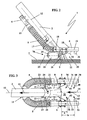
- the suction assembly 1 consists essentially of a suction tube 2, via which the sucked groupage is fed to a collecting container 3, as in Fig. 1 is shown schematically.
- a blowpipe 4 is attached to the suction pipe 2, which branches via a T-shaped socket 15 into two air channels 5, eg air hoses, which open into end pipes 6 closed at the end.
- the tailpipes 6 are - see.
- Fig. 2 - In the predominant operating position of the suction assembly 1 with its longitudinal axes 16 approximately parallel to the bottom surface 7, from which the groupage is to be picked up. The position of the longitudinal axes 16 thus also corresponds to the position of the suction assembly 1 to the bottom surface. 7
- the suction tube 2 has a front suction port 8, which lies in the illustrated embodiment at an angle 9 of about 45 ° to the bottom surface 7.
- the plane 10 of the inlet surface of the suction orifice 8 is at an angle of less than about 70 °, preferably about 45 ° to the bottom surface 7.
- the tail pipes 6 extend to the right and left of the suction tube 2 and extend beyond the suction port 8 of the suction tube 2 ( Fig. 3 ).
- the suction tube 2 and the tail pipes 6 with the air channels 5 are held together on a support body 11.
- the longitudinal axes 16 of the tailpipes 6 and the longitudinal axis 12 of the suction tube 2 lie - in plan view Fig. 3 approximately parallel to one another, wherein the longitudinal axis 12 of the suction tube 2 encloses an angle 17 of approximately 45 ° with the plane of the suction arrangement 1 defined by the longitudinal axes 16 ( Fig. 2 ).
- the suction tube 2 is pivotable relative to the support body 11 about a transverse to the longitudinal axes 12 and 16, approximately parallel to the bottom surface 7 aligned axis of rotation 18, so that the suction assembly 1 even with a change in the angle of the suction tube 2 to the bottom surface 7 with their Longitudinal axes 16 approximately parallel to the bottom surface 7 extends. Regardless of the size of a user who carries the suction assembly on the suction tube 2, a parallelism of the suction assembly 1 is ensured to the bottom surface 7.
- a working area 20 of the suction assembly 1 is defined.
- the working area 20 is below the plane defined by the longitudinal axes 16, which is approximately parallel to the bottom surface 7.
- Fig. 3 shows - suction in the direction of arrow 13 in the suction pipe 2 and a collection container 3 ( Fig. 1 ).
- blowing air is blown into the working area 20.
- the tailpipes 6 blowing nozzles 30, 31, 32, 33, whose respective Blasluftstrom 40, 41, 42 and 43 is directed to the bottom surface of the working area 20, which lies in the area in front of the suction orifice 8.
- the blast air streams 40 to 43 emerging from the blowing nozzles 30 to 33 are advantageously oriented at least partially in the direction of the suction orifice 8. If the working area 20 is divided by an imaginary vertical median plane 14 into two symmetrical halves, then the suction orifice 8 is preferably symmetrical to the median plane 14.
- the tailpipes 6 with the blast nozzles 30 to 33 are arranged in such a way that they - in plan view Fig. 3 - Are symmetrical to the median plane 14 of the working area 20. Relative to the center plane 14, each tuyere 30, 31 is located opposite a tuyere 32 or 33.
- blowing nozzles may be advantageous to provide the alignment of the blowing nozzles in pairs, so that the relative to the center line 14 opposite blowing nozzle pairs 30, 32; 31, 33 are each aligned at the same angle to the bottom surface 7 and the suction opening 8.
- Volume of the blown air to the center plane 14 is divided approximately symmetrically.
- the reaction forces occurring relative to the center plane 14 can be compensated, so that an easy guiding of the suction assembly 1 is given.
- the crossing area two blast air streams is preferably on the center plane 14, so that the vertical direction component triggers no tilting movement about the Saugrohrachse 12; Rather, the vertically upwardly directed direction component counteract the weight of the intake manifold, whereby easier handling is achieved.
- the suction mouth near blowing nozzles 31, 33 a distance a to the suction orifice 8
- the remote blowing nozzles 30 and 32 have a greater distance b to the suction orifice 8.
- the working area 20 is in this embodiment open at the top, ie a through the suction pipe 2 and the suction port 8 and the tailpipes 6 limited window 60 is open.
- the blowing air supplied through the blowing nozzles 30 to 33 is sucked in part via the suction orifice 8 and partly flow upwards through the window 60 and towards the front.
- This open design ensures that leaves, grass, or other obstacles that may cover the crop are blown away.
- the male groupage can be reliably detected and absorbed by the suction air flow of the suction tube 2.
- the Blas Kunststoffdüsen 30 to 34 also have the advantage that they can raise the groupage also from deep grass or depressions on the ground on an air cushion, so that the suction of crop is possible even under unfavorable conditions. Since essentially only the groupage to be absorbed is sucked up, is in the sump. 3 mainly contain the groupage and only a small proportion of foreign bodies. This has the advantage that the volume of the collecting container can be used more effectively for receiving the groupage.
- a spacer 70 which can be placed on the floor surface 7 on the common supporting body 11.
- the spacer 70 is located outside of the working area 20 below the suction tube 2 near the suction port 8.
- FIGS Fig. 1 to 3 are provided as spacers rollers 21 and 22 which are rotatably mounted about a parallel to the bottom surface 7 axis of rotation 23.
- the axes of rotation 23 are - as in particular the top view Fig. 3
- on both sides of the center line 14 each have a roller 21, 22 held in a bracket 24 which is fixed to the support body 11.
- the rollers 22 are designed to be spherical in the axial direction, so that the rollers 21, 22 in the direction of the axis of rotation 23 as a slider or Serve skids.
- a flexible barrier 25 in the form of brushes, flexible cloths or the like is provided between the rollers 21 and 22 and the working area 20.
- These flaps 25 of a flexible material can even spacers Form 70 and be provided as the only measure for distance protection.
- a suction arrangement is shown which after the Fig. 1 to 3 identical in construction.
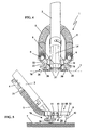
- rollers are in the embodiment of the 4 and 5 Skids provided, which - like the front view in Fig. 4 shows - on both sides of the suction opening 8 below the suction pipe 2 outside the window 60 extend.
- the runners 26 are formed such that the suction assembly 1 is both laterally and easily to move forward and back and slides on the bottom surface 7.
- the design is such that the skids are designed to be curved or rounded in both the transverse and in the longitudinal direction of the suction tube 2.
- the embodiment of the 6 and 7 corresponds to the basic structure of the embodiment of the Fig. 1 to 5 . why the same reference numerals are used for the same parts.
- a blowing nozzle 35 is arranged in the connecting tube 36, which is the suction port 8 - measured in the horizontal of the bottom surface 7 - with a distance c directly opposite ( Fig. 7 ).
- the exiting blast air flow 45 is directed obliquely downward on the bottom surface in the working area 20, wherein the blast air flow 45 has a flow component which points directly to the suction orifice 8.
- tailpipes 6 are located near the suction port 8 blast nozzles 31 and 33 of the Fig. 1 to 5 accounts; but it may be appropriate, even with the closed fork nozzle according to the embodiment of 6 and 7 to arrange suction nozzles near blowing nozzles.
- Casters 21, 22 are shown as spacers 70 to the bottom surface 7, can - as in the embodiment of the 4 and 5 - Even sliders, runners, cloths or the like. Spacers may be provided.
- a suction assembly 1 is shown as an annular nozzle, as shown in the 8 to 12 is shown.
- the annular nozzle consists of a preferably air-guiding ring 50, in the center of which the suction mouth 8 of the suction tube 2 is located.
- the suction port 8 is held by radial struts 49, wherein between the radial struts 49, the ring 50 and the blowpipe 2 windows 60 are limited, which are open.
- the lying under the ring 50 work area 20 is open according to the invention, so that leaves, loose grass, moss or dirt can flow out.
- blowing nozzles 51 to 58 On the bottom surface 7 facing side of the ring 50 are blowing nozzles 51 to 58 ( Fig. 10 ), whose blast air streams 61 to 68 are directed obliquely downward in the direction of the center of the ring 50 on the bottom surface 7. Also in this embodiment it is provided that cancel the reaction forces of the directed onto the bottom surface 7 Blas Kunststoffströme 61 to 68. Therefore, the diametrically opposite to the center of each other Blasluftdüsen are the same design and aligned, so that relative to the center 80 of the annular nozzle occurring reaction forces are largely eliminated. The impinging blast streams are directed upwards.
- the blowing air is also in the embodiment of the 8 to 12 supplied via a blowpipe 4, which branches via a T-piece 15 in two air hoses 5, which open on both sides of the median plane 14 in the air-guiding ring 50. It may be expedient to form the air hoses 5 in the wall of the suction channel 2 and to carry out the air supply to the ring 50 via the radial struts 49.
- a spacer 70 is formed in the form of a ball cap 71, which serves as a skid in all directions of movement of the annular nozzle 50.
- the ball cap 71 is approximately below of the suction tube 2 is arranged on the ring 50 and carries the weight of the suction arrangement. 1
- the annular nozzle 50 has the advantage that the air nozzles 51 to 58 can be targeted to a working area 20 below the suction orifice 8.
- the collected item to be absorbed such as nuts or the like, is emitted from the blast air streams 61 to 68, e.g. raised deep grass to the suction port 8, so that a secure recording is guaranteed.
- Due to the open structure of the annular nozzle 50 with open window 60 between the struts 49 lighter material such as leaves, grass, moss or the like.
- a slider may be provided, which consists of a plurality of individual lamellae 76, which cover the window 60 similar to a fan. If the fan is fully extended, the window 60 is completely closed. If all the windows are closed in this way, the plane of the suction arrangement above the suction orifice 8 is completely closed, so that the lighter air collected by the blower air streams 60 to 68 is also collected via the suction orifice; the suction arrangement forms a Saugtherapies réelle. In this case, the supplied blowing air can be sucked substantially completely, so that an approximately closed air circulation is given.
- the closure element is wholly or partially executed in a transparent material, the surface to be sucked off is visible to the user, so that he can visually monitor the surface to be sucked off and the material to be sucked off.
- the guidance of the suction arrangement is more efficient.
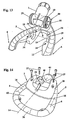
- FIGS. 13 and 14 shows a pivotable attachment of the bottom end of the suction tube 2 with the suction port 8 on the support body 11.
- the support body 11 is preferably made in one piece with the supplying Blas Kunststoffkanälen 5 and the tailpipes 6, which are connected via a connecting tube 36 together blowing air.
- the support body 11 has opposing bearing receivers 19, in which round flanges 29 of the suction tube 2 come to lie rotatably.
- the bearing mounts 19 determine the axis of rotation 18 of the suction tube 2 in the support body 11, around which the round flanges 29 are pivotable together with the suction tube 2.
- the axis of rotation 18 is approximately parallel to the determined by the longitudinal axes 16 of the tailpipes 6 level.
- the bearing mounts 19 and 39 are each designed as a bearing half shells, so that after placing the bearing cap 28, the respective bearing mounts are completely closed and the round flanges 29 enclose the suction tube 2.
- the bearing cap 28 is fixed by fastening screws 27 on the support body 11, for which purpose corresponding screw holes 34 are provided in the support body 11.
- the bearing cap 28 is further provided with a handle 48 through which the user can perform the adjustment of the support body 11 relative to the suction tube 2 after loosening the fastening screws 27. After tightening the mounting screws 27, the suction tube 2 is rotatably fixed in the support body 11 in the set rotational position.
- the one-piece design of the suction channels 5, the tailpipes 6 and the connecting tube 36 makes it possible to form a lying on the median plane 14 Blas Kunststoffstutzen 44 for connection of the blower tube 4.
- the supply of blast air can be done centrally about in the center plane 14 so.
- the suction tube 2 and the blowpipe 4 are - seen in plan view - one above the other.
- a suction fan can be used, wherein the suction fan on the suction side with the suction pipe 2 and on the blast side with the blowpipe 4 can be connected.
- the suction air flow can also be generated by injection of blowing air into the suction pipe 2, so that only the blowing of a blower is used as a drive.
Landscapes
- Life Sciences & Earth Sciences (AREA)
- Environmental Sciences (AREA)
- Cleaning In General (AREA)
- Harvesting Machines For Specific Crops (AREA)
- Floor Finish (AREA)
- Refuse Collection And Transfer (AREA)
- Nozzles For Electric Vacuum Cleaners (AREA)
- Harvester Elements (AREA)
Description
- Die Erfindung betrifft eine Sauganordnung, zum Aufsammeln von Sammelgut von einer Bodenfläche, z. B. zum Aufsammeln von Erntegut nämlich Kleinfrüchten wie Nüssen, Beeren, Oliven, Kaffeekirschen oder dgl. vom Boden nach dem Oberbegriff des Anspruchs 1.
- Beim Ernten von Kleinfrüchten wie Oliven ist es üblich, die Früchte von den Bäumen zu schütteln oder zu schlagen und dann vom Boden aufzusammeln. Hierzu sind Sauggeräte bekannt, die ähnlich einem Staubsauger das am Boden befindliche Gut aufnehmen. Nachteilig ist, daß in dem Sammelbehälter nicht nur das aufzusammelnde Erntegut, sondern auch Laub, Moos, Gras oder dgl. Fremdkörper aufgenommen wird, so daß ein häufiges Entleeren notwendig ist. Dabei muß dann - meist von Hand - das Erntegut von den unerwünschten Fremdkörpern selektiert werden.
- Es sind auch Sauggeräte bekannt, bei denen das Erntegut zusammen mit Laub, Gras oder dgl. Fremdkörper derart in einen Sammelbehälter geführt wird, daß die meist leichteren Fremdkörper ausgeblasen werden und nur das Erntegut zurückgehalten wird. Derartige Geräte sind aber aufwendig und schwer, was für den das Gerät tragenden Benutzer ermüdend ist.
- Aus der
US-A-3,460,327 ist eine Sauganordnung bekannt, deren Saugmund eine "Nulldruckzone" aufweist, deren vertikale Lage durch Ausstellen eines umlaufenden Randes variiert werden kann. Dabei dienen Blasluftströme dem Wegblasen von Material, welches nicht aufgesaugt werden soll. Durch Absenken des Saugmundes über das aufzunehmende Sammelgut kann dieses die Nulldruckzone passieren und wird dann über den Saugschlauch aufgenommen. Der Benutzer muß also den Saugmund gezielt über das aufzunehmende Gut stülpen, bevor dieses eingesaugt wird. - Aus der
US-A-5,499,493 geht eine Sammeleinrichtung hervor, bei der die aufzusammelnden Früchte über rechenartige Zinken vom Boden aufgenommen und - auf den Zinken - in Richtung zum Saugmund der Sauganordnung gefördert werden. Ein im Bereich der Zinkenspitzen vorgesehener Blasstrom ist von der Saugmündung weg nach unten zum Boden gerichtet und bildet eine Luftbarriere, um einmal von den Zinken aufgenommene Früchte auf den Zinken zu halten. - Der Erfindung liegt die Aufgabe zugrunde, eine bekannte Sauganordnung derart weiterzubilden, daß gezielt das gewünschte Sammelgut aufgenommen wird.
- Die Aufgabe wird erfindungsgemäß nach den Merkmalen des Anspruchs 1 gelöst.
- Der aus der Blasdüse austretende Blasluftstrom liegt mit Abstand zur Saugmündung und ist auf die Bodenfläche im Bereich der Saugmündung gerichtet, so daß das aufzunehmende Sammelgut durch den Blasluftstrom in Richtung auf die Saugmündung gefördert wird, wodurch ein leichtes Aufnehmen des Erntegutes über die Saugmündung gewährleistet ist. Insbesondere in tiefem Gras oder aus Bodenvertiefungen kann der Blasluftstrom das aufzusammelnde Sammelgut pneumatisch anheben, so daß überhaupt erst eine Aufnahme mit einem Sauggerät möglich wird. Im Sammelbehälter wird sich daher im wesentlichen nur das Sammelgut sammeln, so daß der Füllungsgrad mit Sammelgut gegenüber herkömmlichen Saugmethoden signifikant erhöht ist, wodurch die Effizienz der Saugaufnahme verbessert ist. Da der Blasluftstrom der Blasdüse zumindest teilweise in Richtung auf die Saugmündung ausgerichtet ist, wird der Blasluftstrom nicht nur Laub, Gras, Moos oder dgl. wegblasen, sondern zugleich das Erntegut in Richtung auf die Saugmündung des Saugrohres fördern. Aufgrund der mehreren Blasdüsen und einer Anordnung, wonach sich zwei Blasdüsen bezogen auf den Arbeitsbereich einander etwa gegenüberliegen, ist eine gute Funktionalität gegeben.
- Ist der zwischen dem Blasluftaustritt und der Saugmündung liegende Arbeitsbereich zumindest über einen Teilbereich von oben einsehbar, ist dem Benutzer eine einfache, zielgerichtete Führung der Sauganordnung möglich. Ist der Teilbereich nach oben offen, können zudem leichtere Fremdkörper von einem schwereren Sammelgut, vorzugsweise einem Erntegut wie Kleinfrüchte, z. B. Kastanien, Nüsse, Beeren, Oliven, Kaffeekirschen oder dgl. weggeblasen werden, so daß über die Saugöffnung im wesentlichen das Erntegut aufgenommen wird. Der Füllungsgrad des Sammelbehälters mit Erntegut ist verbessert, so daß bei einer Entleerung des Sammelbehälters eine manuelle Selektierung des Erntegutes von Fremdkörpern meist entfallen kann.
- Es kann vorteilhaft sein, den offenen Teilbereich über ein Verschlußelement wie einen Schieber o. dgl. ganz oder teilweise verschließbar auszubilden, so daß die auf der Bodenfläche durch den Blasluftstrom mögliche Selektierung des aufzunehmenden Sammelgutes von den wegzublasenden Fremdkörpern einstellbar ist. Wird das Verschlußelement transparent ausgeführt, bleibt auch bei geschlossenem Teilbereich der Blick auf die Bodenfläche frei, was die Führung der Sauganordnung erleichtert. Bei vollständig geschlossenen Teilbereichen kann die Sauganordnung als Saugreiniger für Bodenflächen eingesetzt werden.
- Bevorzugt liegt der Saugmündung eine Blasdüse unmittelbar gegenüber, wodurch die unterstützende Förderung von Kleinfrüchten zur Aufnahme durch die Saugmündung verbessert werden kann.
- Die Eintrittsfläche der Saugmündung und die Bodenfläche liegen in einem Winkel von weniger als 70° zueinander, vorzugsweise etwa 45°, wodurch ein effektives Arbeiten mit einem hohen Aufnahmegrad gegeben ist.
- Bevorzugt haben die bezogen auf den Arbeitsbereich einander etwa gegenüberliegenden Blasdüsen eines Paares jeweils gleiche Ausrichtung, vorzugsweise liegen sie mit gleichen Winkeln zur Bodenfläche. Dadurch wird erreicht, daß die durch das Auftreffen des Blasluftstroms auf die Bodenfläche auftretende Reaktionskraft der einen Düse durch den Blasluftstrom der anderen Düse kompensiert wird. Die erfindungsgemäße Sauganordnung läßt sich einfach handhaben. Kreuzen sich die Blasluftströme eines Paares vorzugsweise etwa auf einer Mittelebene des Arbeitsbereiches der Sauganordnung oder nahe dem Zentrum der Saugmündung, so erhalten die sich treffenden Luftströme eine Richtungskomponente nach oben, insbesondere senkrecht nach oben, wodurch leichte Teile aufgewirbelt werden.
- Es kann zweckmäßig sein, die Blasluftdüsen mit unterschiedlichen Winkeln zur Bodenfläche anzuordnen, um ein unterschiedlich tiefes Eindringen der Blasluft z.B. im Gras zu ermöglichen.
- In einer vorteilhaften Ausführungsform sind mehrere Blasdüsen auf einem die Saugmündung als Zentrum aufweisenden Kreis angeordnet, wobei alle Blasdüsen des Kreises zweckmäßig unter einem gleichen Winkel zur Bodenfläche liegen. Alle Düsen fördern zum Zentrum des Kreises, in dem die Saugmündung des Saugrohres angeordnet ist. Über offene Fenster innerhalb des Kreises fliegt das leichte Gut davon; nur die schwereren Kleinfrüchte bleiben unter der Saugmündung liegen und werden vom Saugluftstrom aufgenommen.
- Um dem Benutzer ein kräfteschonendes Führen der erfindungsgemäßen Sauganordnung zu ermöglichen, ist vorgesehen, daß das Saugrohr und die Blasdüsen an einem gemeinsamen Tragkörper gehalten sind und der Tragkörper einen auf die Bodenfläche aufsetzbaren Abstandshalter aufweist. Der Abstandshalter kann in Form von Lappen, eines Gleitkörpers, insbesondere eines Gleitschuhs, oder auch in Form einer Laufrolle ausgebildet sein, wobei die Drehachse einer Laufrolle parallel zur Bodenfläche und vorzugsweise etwa parallel zum Saugrohr liegt. Dabei ist die Laufrolle axial ballig gestaltet, so daß nicht nur in Drehrichtung eine einfache Bewegung möglich ist, sondern auch in Richtung der Drehachse selbst, in der die Laufrolle dann als Gleitkufe arbeitet.
- In besonderer Weiterbildung der Erfindung ist der Winkel zwischen dem Saugrohr und der die Blasdüse aufweisenden Anordnung verstellbar, so daß die Sauganordnung auch bei Änderung des Winkels des Saugrohres mit ihrer Längsachse parallel zur Bodenfläche verläuft. Unabhängig von der Größe eines Benutzers, der die Sauganordnung am Saugrohr trägt, ist eine Parallelität der Sauganordnung zur Bodenfläche gewährleistet.
- Weitere Merkmale der Erfindung ergeben sich aus den weiteren Ansprüchen, der Beschreibung und der Zeichnung, in der nachstehend im einzelnen beschriebene Ausführungsbeispiele dargestellt sind. Es zeigen:
- Fig. 1
- eine perspektivische Ansicht auf eine Sauganordnung in Form einer Gabeldüse,
- Fig. 2
- eine Seitenansicht der Sauganordnung nach
Fig. 1 , - Fig. 3
- eine Draufsicht auf die Sauganordnung nach
Fig. 1 , - Fig. 4
- eine Ansicht einer Sauganordnung nach
Fig. 1 mit einem Gleitschuh als Abstandshalter, - Fig. 5
- eine Seitenansicht der Sauganordnung nach
Fig. 4 , - Fig. 6
- eine perspektivische Ansicht einer geschlossenen Gabeldüse in einem der offenen Gabeldüse nach
Fig. 1 entsprechenden Aufbau, - Fig. 7
- eine Draufsicht auf die geschlossene Gabeldüse nach
Fig. 6 , - Fig. 8
- eine perspektivische Ansicht einer Runddüse,
- Fig. 9
- eine Seitenansicht der Runddüse nach
Fig. 8 , - Fig. 10
- eine Ansicht von unten auf die Runddüse nach
Fig. 8 , - Fig. 11
- eine Frontansicht der Runddüse nach
Fig. 8 , - Fig. 12
- eine Draufsicht auf die Runddüse nach
Fig. 8 , - Fig. 13
- eine perspektivische Explosionsdarstellung der Verbindung zwischen Saugrohr und Trageinrichtung,
- Fig. 14
- eine perspektivische Darstellung der Trageinrichtung mit einem das Saugrohr festlegenden Deckel.
- Die in
Fig. 1 gezeigte Sauganordnung 1 dient dem Aufsaugen von Sammelgut wie losen Teilen von einer Bodenfläche 7. Die Sauganordnung 1 ist bevorzugt zum Aufsaugen von Sammelgut, nämlich Erntegut wie Kleinfrüchten, beispielsweise Kastanien, Nüssen, Beeren, Oliven, Kaffeekirschen oder dgl. von einer Bodenfläche ausgebildet. Die erfindungsgemäße Sauganordnung 1 kann aber auch zur effektiven Reinigung von Bodenflächen eingesetzt werden. - Die Sauganordnung 1 besteht im wesentlichen aus einem Saugrohr 2, über das das aufgesaugte Sammelgut einem Sammelbehälter 3 zugeführt ist, wie er in
Fig. 1 schematisch dargestellt ist. - Wie
Fig. 2 zeigt, ist am Saugrohr 2 ein Blasrohr 4 befestigt, welches über einen T-förmigen Stutzen 15 in zwei Luftkanäle 5, z.B. Luftschläuche verzweigt, die in endseitig geschlossene Endrohre 6 münden. Die Endrohre 6 liegen - vgl.Fig. 2 - in der überwiegenden Betriebshaltung der Sauganordnung 1 mit ihren Längsachsen 16 etwa parallel zur Bodenfläche 7, von der das Sammelgut aufzulesen ist. Die Lage der Längsachsen 16 entspricht somit auch der Lage der Sauganordnung 1 zur Bodenfläche 7. - Das Saugrohr 2 weist eine vordere Saugmündung 8 auf, die im gezeigten Ausführungsbeispiel unter einem Winkel 9 von etwa 45° zur Bodenfläche 7 liegt. Zweckmäßig liegt die Ebene 10 der Eintrittsfläche der Saugmündung 8 unter einem Winkel von kleiner etwa 70°, vorzugsweise etwa 45° zur Bodenfläche 7. Die Endrohre 6 erstrecken sich rechts und links neben dem Saugrohr 2 und überragen die Saugmündung 8 des Saugrohrs 2 (
Fig. 3 ). - Das Saugrohr 2 und die Endrohre 6 mit den Luftkanälen 5 sind an einem Tragkörper 11 gemeinsam gehalten. Die Längsachsen 16 der Endrohre 6 und die Längsachse 12 des Saugrohres 2 liegen - in Draufsicht nach
Fig. 3 - etwa parallel zueinander, wobei die Längsachse 12 des Saugrohres 2 mit der durch die Längsachsen 16 definierten Ebene der Sauganordnung 1 einen Winkel 17 von etwa 45° einschließt (Fig. 2 ). Bevorzugt ist das Saugrohr 2 relativ zum Tragkörper 11 um eine quer zu den Längsachsen 12 und 16 liegende, etwa parallel zur Bodenfläche 7 ausgerichtete Drehachse 18 verschwenkbar, so daß die Sauganordnung 1 selbst auch bei einer Änderung des Winkels des Saugrohres 2 zur Bodenfläche 7 mit ihren Längsachsen 16 etwa parallel zur Bodenfläche 7 verläuft. Unabhängig von der Größe eines Benutzers, der die Sauganordnung am Saugrohr 2 trägt, ist eine Parallelität der Sauganordnung 1 zur Bodenfläche 7 gewährleistet. - Zwischen den die Saugmündung 8 überragenden Endrohren 6 und der Saugmündung 8 selbst ist ein Arbeitsbereich 20 der Sauganordnung 1 definiert. Der Arbeitsbereich 20 liegt unterhalb der durch die Längsachsen 16 definierten Ebene, die etwa parallel zur Bodenfläche 7 liegt. Aus diesem Arbeitsbereich 20 strömt - wie
Fig. 3 zeigt - Saugluft in Pfeilrichtung 13 in das Saugrohr 2 ein und zum Sammelbehälter 3 (Fig. 1 ). Gleichzeitig wird in den Arbeitsbereich 20 Blasluft eingeblasen. Hierzu weisen die Endrohre 6 Blasdüsen 30, 31, 32, 33 auf, deren jeweiliger Blasluftstrom 40, 41, 42 und 43 auf die Bodenfläche des Arbeitsbereiches 20 gerichtet ist, der in dem Bereich vor der Saugmündung 8 liegt. Die aus den Blasdüsen 30 bis 33 austretenden Blasluftströme 40 bis 43 sind vorteilhaft zumindest teilweise in Richtung auf die Saugmündung 8 ausgerichtet. Wird der Arbeitsbereich 20 durch eine gedachte senkrechte Mittelebene 14 in zwei symmetrische Hälften geteilt, so liegt die Saugmündung 8 bevorzugt symmetrisch zur Mittelebene 14. Auch die Endrohre 6 mit den Blasdüsen 30 bis 33 sind derart angeordnet, daß sie - in Draufsicht nachFig. 3 - symmetrisch zur Mittelebene 14 des Arbeitsbereiches 20 liegen. Bezogen auf die Mittelebene 14 liegt jeder Blasdüse 30, 31 eine Blasdüse 32 bzw. 33 direkt gegenüber. Dabei kann es vorteilhaft sein, die Ausrichtung der Blasdüsen jeweils paarweise vorzusehen, so daß die bezogen auf die Mittellinie 14 einander gegenüberliegenden Blasdüsenpaare 30, 32; 31, 33 jeweils in dem gleichen Winkel zur Bodenfläche 7 und zur Saugöffnung 8 ausgerichtet liegen. Volumenmäßig ist die Blasluft zur Mittelebene 14 etwa symmetrisch aufgeteilt. Die sich unterhalb der durch die Längsachsen 16 definierten Ebene treffenden Luftströme 40 und 42 und/oder 41 und 43 erhalten dadurch eine Richtungskomponente nach oben, vorzugsweise senkrecht nach oben. Leichte Teile werden aufgewirbelt. Ferner können auch die auftretenden Reaktionskräfte bezogen auf die Mittelebene 14 kompensiert werden, so daß ein leichtes Führen der Sauganordnung 1 gegeben ist. Insbesondere der Kreuzungsbereich zweier Blasluftströme liegt bevorzugt auf der Mittelebene 14, so daß die senkrechte Richtungskomponente keine Kippbewegung um die Saugrohrachse 12 auslöst; vielmehr kann die senkrecht nach oben gerichtete Richtungskomponente dem Gewicht der Saugrohranordnung entgegenwirken, wodurch eine leichtere Handhabung erzielt ist. - Wie sich aus den
Fig. 1 bis 3 ergibt, liegen die Blasluftaustritte der Blasdüsen 30 bis 33 bezogen auf die Längserstreckung des Saugrohres 2 mit einem in der Horizontalen zur Bodenfläche 7 gemessenen Abstand a bzw. b zur Saugöffnung 8. So haben die saugmündungsnahen Blasdüsen 31, 33 einen Abstand a zur Saugmündung 8, während die entfernt liegenden Blasdüsen 30 und 32 einen größeren Abstand b zur Saugmündung 8 aufweisen. Der Arbeitsbereich 20 ist in diesem Ausführungsbeispiel nach oben offen, d.h. ein durch das Saugrohr 2 bzw. die Saugmündung 8 und die Endrohre 6 begrenztes Fenster 60 ist offen. Die durch die Blasdüsen 30 bis 33 zugeführte Blasluft wird zum Teil über die Saugmündung 8 abgesaugt und zum Teil nach oben durch das Fenster 60 und nach vorne abströmen. Durch diese offene Bauweise wird erreicht, daß Laub, Gras, oder andere Hindernisse, die das Erntegut bedecken könnten, weggeblasen werden. Das aufzunehmende Sammelgut kann von dem Saugluftstrom des Saugrohres 2 sicher erfaßt und aufgenommen werden. Die Blasluftdüsen 30 bis 34 haben darüber hinaus den Vorteil, daß sie das Sammelgut auch aus tiefem Gras oder aus Vertiefungen am Boden auf ein Luftpolster anheben können, so daß das Absaugen von Erntegut auch unter ungünstigen Bedingungen möglich ist. Da im wesentlichen nur das aufzunehmende Sammelgut aufgesaugt wird, ist im Sammelbehälter 3 überwiegend das Sammelgut enthalten und nur ein geringer Anteil von Fremdkörpern. Dies hat den Vorteil, daß das Volumen des Sammelbehälters zum Aufnehmen des Sammelgutes effektiver genutzt werden kann. - Um dem Benutzer eine einfache Führung der Sauganordnung 1 zu ermöglichen, ist vorgesehen, am gemeinsamen Tragkörper 11 einen auf die Bodenfläche 7 aufsetzbaren Abstandshalter 70 zu befestigen. Der Abstandshalter 70 liegt außerhalb des Arbeitsbereiches 20 unterhalb des Saugrohres 2 nahe der Saugmündung 8. Im Ausführungsbeispiel nach den
Fig. 1 bis 3 sind als Abstandshalter Laufrollen 21 und 22 vorgesehen, die um eine zur Bodenfläche 7 parallele Drehachse 23 drehbar gelagert sind. Die Drehachsen 23 liegen dabei - wie insbesondere die Draufsicht nachFig. 3 zeigt - parallel zu den Längsachsen der Endrohre 6 bzw. zur Längsachse 12 des Saugrohres 2. Wie dargestellt, sind auf beiden Seiten der Mittellinie 14 je eine Laufrolle 21, 22 in einem Bügel 24 gehalten, der an dem Tragkörper 11 festgelegt ist. Um nicht nur eine leichte rollende seitliche Hin- und Herbewegung zu gewährleisten, sondern auch eine Vorwärtsbewegung mit wenig Kraftaufwand ausführen zu können, sind die Laufrollen 22 in Achsrichtung ballig ausgeführt, so daß die Laufrollen 21, 22 in Richtung der Drehachse 23 als Gleiter bzw. Gleitkufen dienen. - Um die Schmutzbelastung der drehbaren Laufrollen 21 und 22 gering zu halten, ist zwischen den Laufrollen 21 und 22 und dem Arbeitsbereich 20 eine flexible Sperre 25 in Form von Bürsten, flexiblen Lappen oder dgl. vorgesehen. Diese Lappen 25 aus einem flexiblen Material können selbst auch Abstandshalter 70 bilden und als einzige Maßnahme zur Abstandswahrung vorgesehen sein.
- Im Ausführungsbeispiel nach
Fig. 4 und 5 ist eine Sauganordnung gezeigt, die der nach denFig. 1 bis 3 im Aufbau identisch entspricht. Anstelle von Laufrollen sind im Ausführungsbeispiel nach denFig. 4 und 5 Gleitkufen vorgesehen, die sich - wie die Frontansicht inFig. 4 zeigt - beidseitig der Saugöffnung 8 unterhalb des Saugrohres 2 außerhalb des Fensters 60 erstrecken. Die Kufen 26 sind derart ausgebildet, daß die Sauganordnung 1 sowohl seitlich als auch leicht nach vorne und zurück zu bewegen ist und auf der Bodenfläche 7 gleitet. Die Formgestaltung ist derart, daß die Kufen sowohl in Quer- als auch in Längsrichtung zum Saugrohr 2 ballig bzw. gerundet gestaltet sind. - Wie sich aus der Frontansicht nach
Fig. 4 ergibt, sind die saugmündungsfern liegenden Düsen 30 und 32 unter einem flacheren Winkel 37 zur Bodenfläche 7 ausgerichtet als die saugmündungsnah liegenden Düsen 31 und 33, die unter einem Winkel 38 zur Bodenfläche 7 liegen.Fig. 4 kann auch entnommen werden, daß die bezogen auf die Mittelebene 14 sich paarweise gegenüberliegenden Düsen 30, 32; 31, 33 räumlich mit dem gleichen Winkel 37 bzw. 38 ausgerichtet liegen, so daß sich bezogen auf eine Mittelebene 14 ausgeglichene Reaktionskräfte ergeben. Die sich in der Mittelebene treffenden Blasströme erhalten eine Richtungskomponente nach oben. - Das Ausführungsbeispiel nach den
Fig. 6 und 7 entspricht im Grundaufbau dem Ausführungsbeispiel nach denFig. 1 bis 5 , weshalb für gleiche Teile gleiche Bezugszeichen verwendet sind. - In Abweichung von den Ausführungsbeispielen nach den
Fig. 1 bis 5 sind die Endrohre 6 offen und über ein Verbindungsrohr 36 miteinander strömungsführend verbunden. Mittig zur Mittelebene 14 ist im Verbindungsrohr 36 eine Blasdüse 35 angeordnet, die der Saugmündung 8 - gemessen in der Horizontalen der Bodenfläche 7 - mit einem Abstand c direkt gegenüberliegt (Fig. 7 ). Der austretende Blasluftstrom 45 ist schräg abwärts auf die Bodenfläche im Arbeitsbereich 20 gerichtet, wobei der Blasluftstrom 45 eine Strömungskomponente aufweist, die direkt auf die Saugmündung 8 zeigt. - In den Endrohren 6 sind die nahe der Saugmündung 8 liegenden Blasdüsen 31 und 33 der
Fig. 1 bis 5 entfallen; es kann aber zweckmäßig sein, auch bei der geschlossenen Gabeldüse nach dem Ausführungsbeispiel derFig. 6 und 7 saugmündungsnahe Blasdüsen anzuordnen. - Auch wenn im Ausführungsbeispiel nach den
Fig. 6 und 7 Laufrollen 21, 22 als Abstandshalter 70 zur Bodenfläche 7 gezeigt sind, können - wie im Ausführungsbeispiel nach denFig. 4 und 5 - auch Gleiter, Kufen, Lappen oder dgl. Abstandshalter vorgesehen sein. - In einem dritten Ausführungsbeispiel der Erfindung ist eine Sauganordnung 1 als Ringdüse gezeigt, wie sie in den
Fig. 8 bis 12 dargestellt ist. Die Ringdüse besteht aus einem vorzugsweise luftführenden Ring 50, in dessen Zentrum die Saugmündung 8 des Saugrohres 2 liegt. Die Saugmündung 8 ist über Radialstreben 49 gehalten, wobei zwischen den Radialstreben 49, dem Ring 50 und dem Blasrohr 2 Fenster 60 begrenzt sind, die offen sind. Der unter dem Ring 50 liegende Arbeitsbereich 20 ist erfindungsgemäß nach oben offen, so daß Laub, loses Gras, Moos oder Schmutz abströmen kann. - Auf der der Bodenfläche 7 zugewandten Seite des Rings 50 sind Blasdüsen 51 bis 58 (
Fig. 10 ) vorgesehen, deren Blasluftströme 61 bis 68 schräg nach unten in Richtung auf das Zentrum des Rings 50 auf die Bodenfläche 7 gerichtet sind. Auch in dieser Ausführungsform ist vorgesehen, daß sich die Reaktionskräfte der auf die Bodenfläche 7 gerichteten Blasluftströme 61 bis 68 aufheben. Daher sind die zum Zentrum einander diametral gegenüberliegenden Blasluftdüsen gleich ausgebildet und gleich ausgerichtet, so daß bezogen auf das Zentrum 80 der Ringdüse auftretende Reaktionskräfte weitgehend aufgehoben sind. Die sich treffenden Blasströme werden nach oben gelenkt. - Die Blasluft wird auch im Ausführungsbeispiel nach den
Fig. 8 bis 12 über ein Blasrohr 4 zugeführt, welches über ein T-Stück 15 in zwei Luftschläuche 5 verzweigt, die auf beiden Seiten der Mittelebene 14 in den luftführenden Ring 50 einmünden. Es kann zweckmäßig sein, die Luftschläuche 5 in der Wandung des Saugkanals 2 auszubilden und die Luftzuführung zum Ring 50 über die Radialstreben 49 auszuführen. - Am Ring 50 ist ein Abstandshalter 70 in Form einer Kugelkappe 71 ausgebildet, die in allen Bewegungsrichtungen der Ringdüse 50 als Gleitkufe dient. Die Kugelkappe 71 ist etwa unterhalb des Saugrohrs 2 am Ring 50 angeordnet und trägt das Gewicht der Sauganordnung 1.
- Die Ringdüse 50 hat den Vorteil, daß die Lüftdüsen 51 bis 58 gezielt auf einen Arbeitsbereich 20 unterhalb der Saugmündung 8 ausgerichtet werden können. Das aufzusaugende Sammelgut wie Nüsse oder dgl. wird von den Blasluftströmen 61 bis 68 aus z.B. tiefem Gras zur Saugöffnung 8 angehoben, so daß eine sichere Aufnahme gewährleistet ist. Aufgrund der offenen Struktur der Ringdüse 50 mit offenen Fenster 60 zwischen den Streben 49 wird leichteres Gut wie Laub, Gras, Moos oder dgl. durch die zwischen den Streben 49 liegenden Fenster wegfliegen, so daß der Sammelbehälter mit einem guten Füllungsgrad mit dem Sammelgut gefüllt wird. Kreuzen sich die Luftströme 61 bis 68 unterhalb des Zentrums 80 der Saugmündung 8, wird eine gute Aufnahme des Sammelgutes erzielt. Selbst in Vertiefungen im Boden oder im Gras gehaltene Gegenstände werden gelöst und der Saugöffnung 8 zugeführt.
- Vorteilhaft ist das von den Radialstreben 49 und dem Ring 50 begrenzte Fenster 60 durch ein Verschlußelement 75 ganz oder teilweise verschließbar (
Fig. 12 ). Hierzu kann ein Schieber vorgesehen sein, der aus mehreren Einzellamellen 76 besteht, die ähnlich einem Fächer das Fenster 60 abdecken. Wird der Fächer vollständig ausgefahren, ist das Fenster 60 vollständig verschlossen. Werden alle Fenster auf diese Weise geschlossen, ist die Ebene der Sauganordnung oberhalb der Saugmündung 8 vollständig geschlossen, so daß das von den Blasluftströmen 60 bis 68 aufgewirbelte leichtere Sammelgut ebenfalls über die Saugmündung abgesaugt wird; die Sauganordnung bildet ein Saugreinigungsgerät. Dabei kann die zugeführte Blasluft im wesentlichen vollständig abgesaugt werden, so daß ein etwa geschlossener Luftkreislauf gegeben ist. Wird das Verschlußelement ganz oder teilweise in einem transparenten Material ausgeführt, ist die abzusaugende Fläche für den Benutzer einsehbar, so daß er die abzusaugende Fläche und das abzusaugende Gut optisch überwachen kann. Die Führung der Sauganordnung ist effizienter. - Das Ausführungsbeispiel nach den
Fig. 13 und 14 zeigt eine verschwenkbare Befestigung des bodenseitigen Endes des Saugrohres 2 mit der Saugmündung 8 an dem Tragkörper 11. In dem gezeigten Ausführungsbeispiel ist der Tragkörper 11 vorzugsweise einteilig mit den zuführenden Blasluftkanälen 5 und den Endrohren 6 ausgeführt, die über ein Verbindungsrohr 36 miteinander blasluftführend verbunden sind. Der Tragkörper 11 weist einander gegenüberliegende Lageraufnahmen 19 auf, in welche Rundflansche 29 des Saugrohres 2 drehbar zu liegen kommen. Die Lageraufnahmen 19 bestimmen die Drehachse 18 des Saugrohres 2 im Tragkörper 11, um die die Rundflansche 29 zusammen mit dem Saugrohr 2 verschwenkbar sind. Die Drehachse 18 liegt etwa parallel zu der durch die Längsachsen 16 der Endrohre 6 bestimmten Ebene. - Nach Einsetzen der Rundflansche 29 in die Lageraufnahmen 19 wird die Anordnung durch einen Lagerdeckel 28 geschlossen, in dem Lageraufnahmen 39 ausgebildet sind. Die Lageraufnahmen 19 und 39 sind jeweils als Lagerhalbschalen gestaltet, so daß nach Aufsetzen des Lagerdeckels 28 die jeweiligen Lageraufnahmen vollständig geschlossen sind und die Rundflansche 29 des Saugrohres 2 umschließen. Der Lagerdeckel 28 wird durch Befestigungsschrauben 27 am Tragkörper 11 festgelegt, wozu im Tragkörper 11 entsprechende Schraublöcher 34 vorgesehen sind. Der Lagerdeckel 28 ist ferner mit einem Griff 48 versehen, über den der Benutzer nach Lockern der Befestigungsschrauben 27 die Verstellung des Tragkörpers 11 relativ zum Saugrohr 2 ausführen kann. Nach Anziehen der Befestigungsschrauben 27 ist das Saugrohr 2 im Tragkörper 11 in der eingestellten Drehlage drehfest fixiert.
- Die einteilige Ausführung der Saugkanäle 5, der Endrohre 6 und des Verbindungsrohres 36 gibt die Möglichkeit, einen auf der Mittelebene 14 liegenden Blasluftstutzen 44 zum Anschluß des Blasrohres 4 auszubilden. Die Zuführung der Blasluft kann so etwa in der Mittelebene 14 zentral erfolgen. Das Saugrohr 2 und das Blasrohr 4 liegen - in Draufsicht gesehen - übereinander.
- Als Antrieb für die erfindungsgemäße Sauganordnung 1 kann ein Sauggebläse dienen, wobei das Sauggebläse auf der Saugseite mit dem Saugrohr 2 und auf der Blasseite mit dem Blasrohr 4 verbunden werden kann. Um zu vermeiden, das Sammelgut durch das Sauggebläse zu saugen, kann der Saugluftstrom auch durch Injektion von Blasluft in das Saugrohr 2 generiert werden, so daß ausschließlich der Blasstrom eines Blasgerätes als Antrieb genutzt wird.
Claims (19)
- Sauganordnung, zum Aufsammeln von Sammelgut von einer Bodenfläche (7), z. B. zur Aufnahme von Erntegut, nämlich Kleinfrüchten wie Kastanien, Nüssen, Beeren, Oliven oder dgl. vom Boden, mit einem zur Aufnahme und Weiterleitung des Sammelgutes in einen Sammelbehälter (3) vorgesehenen Saugrohr (2), dessen Saugmündung (8) der Bodenfläche (7) zugewandt liegt, und mit einem im Bereich der Saugmündung (8) liegenden Arbeitsbereich (20) der Sauganordnung (1) sowie einer Blasdüse (30 bis 33; 35; 51 bis 58), deren Blasluftstrom (40 bis 43, 45, 61 bis 68) zur Bodenfläche (7) gerichtet ist,
dadurch gekennzeichnet, daß mehrere Blasdüsen (30 bis 33; 35; 51 bis 58) vorgesehen sind, daß zum pneumatischen Anheben des Sammelgutes von der Bodenfläche (7) der aus einem Blasluftaustritt einer Blasdüse (30 bis 33; 35; 51 bis 58) austretende Blasluftstrom (40 bis 43, 45, 61 bis 68) auf die Bodenfläche (7) in den Arbeitsbereich (20) und zur Förderung des Sammelgutes in Richtung auf die Saugmündung (8) zumindest teilweise in Richtung auf die Saugmündung (8) ausgerichtet ist, wobei der Blasluftaustritt der Blasdüsen (30 bis 33; 35; 51 bis 58) und die Saugmündung (8) des Saugrohres (2) mit in der Horizontalen zur Bodenfläche (7) gemessenen Abständen (a, b, c) zueinander liegen, wobei sich bezogen auf den Arbeitsbereich (20) zwei Blasdüsen (30, 32; 31, 33; 51, 55; 52, 56; 53, 57; 54, 58) einander etwa gegenüberliegen. - Saugrohr nach Anspruch 1,
dadurch gekennzeichnet, daß der zwischen dem Blasluftaustritt und der Saugmündung (8) liegende Arbeitsbereich (20) zumindest über einen Teilbereich von oben einsehbar ist. - Sauganordnung nach Anspruch 1 oder 2,
dadurch gekennzeichnet, daß der zwischen dem Blasluftaustritt und der Saugmündung (8) liegende Arbeitsbereich (20) zumindest über einen Teilbereich nach oben offen ist. - Sauganordnung nach Anspruch 3,
dadurch gekennzeichnet, daß der offene Teilbereich über ein Verschlußelement (75), vorzugsweise einen Schieber, ganz oder teilweise verschließbar ist. - Sauganordnung nach Anspruch 4,
dadurch gekennzeichnet, daß das Verschlußelement (75), aus einem transparenten Material besteht. - Sauganordnung nach einem der Ansprüche 1 bis 5,
dadurch gekennzeichnet, daß der Saugmündung (8) eine Blasdüse (35) gegenüberliegt. - Sauganordnung nach einem der Ansprüche 1 bis 6,
dadurch gekennzeichnet, daß zwischen der Eintrittsebene (10) der Saugmündung (8) und der Bodenfläche (7) ein Winkel (9) von kleiner etwa 70°, vorzugsweise etwa 45° eingeschlossen ist. - Sauganordnung nach Anspruch 1,
dadurch gekennzeichnet, daß die Blasluftströme (40,42; 41,43; 61,65; 62,66; 63,67; 64,68) eines Paares vorzugsweise mit gleichen Winkeln (37, 38) zur Bodenfläche (7) ausgerichtet sind. - Sauganordnung nach einem der Ansprüche 1 bis 8,
dadurch gekennzeichnet, daß einige Blasluftdüsen mit unterschiedlichen Winkeln (37, 38) zur Bodenfläche (7) liegen. - Sauganordnung nach einem der Ansprüche 1 bis 9,
dadurch gekennzeichnet, daß mehrere Blasdüsen (51 bis 58) auf einem die Saugmündung (8) als Zentrum (80) aufweisenden, vorzugsweise luftführenden Ring (50) angeordnet sind. - Sauganordnung nach Anspruch 10,
dadurch gekennzeichnet, daß alle Blasdüsen (51 bis 58) des Ringes (50) unter einem gleichen Winkel zur Bodenfläche (7) liegen. - Sauganordnung nach einem der Ansprüche 8 bis 11,
dadurch gekennzeichnet, daß sich die Blasluftströme (40,42; 41,43; 61,65; 62,66; 63,67; 64,68) eines Paares kreuzen, vorzugsweise etwa auf einer Mittelebene (14) des Arbeitsbereiches (20) oder nahe dem Zentrum (80) der Saugmündung (8). - Sauganordnung nach einem der Ansprüche 1 bis 12,
dadurch gekennzeichnet, daß das Saugrohr (2) und die Blasdüsen (30 bis 33, 35, 51 bis 58) an einem gemeinsamen Tragkörper (11) gehalten sind und der Tragkörper (11) einen auf die Bodenfläche (7) aufsetzbaren Abstandshalter (70) aufweist. - Sauganordnung nach Anspruch 13,
dadurch gekennzeichnet, daß der Abstandshalter (70) aus einem Gleitkörper (26), insbesondere aus einer oder mehreren Gleitkufen gebildet ist. - Sauganordnung nach Anspruch 1,
dadurch gekennzeichnet, daß der Abstandshalter (70) eine Laufrolle (21, 22) ist, deren Drehachse (23) etwa parallel zur Bodenfläche (7) und vorzugsweise etwa parallel zum Saugrohr (2) liegt. - Sauganordnung nach Anspruch 15,
dadurch gekennzeichnet, daß die Laufrolle (21, 22) in Richtung der Drehachse (23) ballig gestaltet ist. - Sauganordnung nach Anspruch 13,
dadurch gekennzeichnet, daß der Abstandshalter (70) aus einem flexiblen Material, insbesondere aus Lappen (25) besteht. - Sauganordnung nach einem der Ansprüche 1 bis 17,
dadurch gekennzeichnet, daß die Blasluft volumenmäßig gleichmäßig auf beide Seiten einer Mittelebene (18) des Arbeitsbereichs (20) aufgeteilt ist. - Sauganordnung nach einem der Ansprüche 1 bis 18,
dadurch gekennzeichnet, daß der Winkel (17) zwischen dem Saugrohr (2) und der die Blasdüse (30,32; 31,33; 51,55; 52,56; 53,57; 54,58) aufweisenden Anordnung verstellbar ist.
Applications Claiming Priority (2)
| Application Number | Priority Date | Filing Date | Title |
|---|---|---|---|
| DE102004025197 | 2004-05-22 | ||
| DE102004025197A DE102004025197A1 (de) | 2004-05-22 | 2004-05-22 | Sauganordnung für eine Bodenfläche |
Publications (2)
| Publication Number | Publication Date |
|---|---|
| EP1597961A1 EP1597961A1 (de) | 2005-11-23 |
| EP1597961B1 true EP1597961B1 (de) | 2008-07-09 |
Family
ID=34936255
Family Applications (1)
| Application Number | Title | Priority Date | Filing Date |
|---|---|---|---|
| EP05009991A Expired - Lifetime EP1597961B1 (de) | 2004-05-22 | 2005-05-07 | Sauganordnung für eine Bodenfläche |
Country Status (6)
| Country | Link |
|---|---|
| US (1) | US7441304B2 (de) |
| EP (1) | EP1597961B1 (de) |
| AT (1) | ATE400173T1 (de) |
| BR (1) | BRPI0501840A (de) |
| DE (2) | DE102004025197A1 (de) |
| ES (1) | ES2309614T3 (de) |
Families Citing this family (12)
| Publication number | Priority date | Publication date | Assignee | Title |
|---|---|---|---|---|
| DE102004025197A1 (de) * | 2004-05-22 | 2005-12-08 | Andreas Stihl Ag & Co. Kg | Sauganordnung für eine Bodenfläche |
| US7937799B2 (en) * | 2006-09-19 | 2011-05-10 | Mark Aaron Riggs | Container cleaning machine |
| US8621709B2 (en) | 2006-12-12 | 2014-01-07 | G.B.D. Corp. | Multi-strut cleaning head |
| US20140215733A1 (en) * | 2010-02-10 | 2014-08-07 | Roger P. Vanderlinden | Gutter broom and gutter broom system |
| ES2399174B1 (es) * | 2011-08-08 | 2014-04-11 | Alfonso MORAL MORAL | Cuasi máquina recolectora de frutos agrícolas del suelo por impulsión-aspiración, de gran capacidad |
| JP6471046B2 (ja) * | 2015-06-12 | 2019-02-13 | 日本植生株式会社 | 植生材料採取方法及び装置 |
| US9961838B2 (en) * | 2015-11-23 | 2018-05-08 | Corey Andri HORTH | Lawn debris collection assembly |
| RU169250U1 (ru) * | 2016-03-31 | 2017-03-13 | Федеральное государственное бюджетное образовательное учреждение высшего образования "Уральский государственный горный университет" (ФГБОУ ВО "УГГУ") | Транспортное средство для пылеулавливания |
| RU169496U1 (ru) * | 2016-05-16 | 2017-03-21 | Федеральное государственное бюджетное образовательное учреждение высшего образования "Уральский государственный горный университет" (ФГБОУ ВО "УГГУ") | Транспортное средство для пылеулавливания |
| CN108338010A (zh) * | 2018-01-24 | 2018-07-31 | 戴久林 | 吹吸一体机 |
| US12404041B2 (en) * | 2020-12-21 | 2025-09-02 | Massachusetts Institute Of Technology | Bi-modal chemical-electric space propulsion |
| CN114766200B (zh) * | 2022-05-20 | 2023-06-20 | 河南理工大学 | 一种精准采摘装置 |
Family Cites Families (11)
| Publication number | Priority date | Publication date | Assignee | Title |
|---|---|---|---|---|
| US3460327A (en) * | 1966-07-11 | 1969-08-12 | Up Right Inc | Apparatus for harvesting fruit |
| US3663984A (en) * | 1970-04-03 | 1972-05-23 | Carpetech Corp | Portable vacuum carpet and upholstery cleaning apparatus |
| US3774262A (en) * | 1970-04-03 | 1973-11-27 | Carpetech Corp | Portable vacuum carpet and upholstery cleaning apparatus |
| US4127913A (en) * | 1977-11-11 | 1978-12-05 | Monson Clifford L | Fabric cleaning device |
| US4499713A (en) * | 1982-06-03 | 1985-02-19 | Stone Emory B | Nut harvester |
| US5499493A (en) * | 1994-09-08 | 1996-03-19 | Rosset; Rene R. | Fruit harvester |
| US6041472A (en) * | 1995-11-06 | 2000-03-28 | Bissell Homecare, Inc. | Upright water extraction cleaning machine |
| US6167587B1 (en) * | 1997-07-09 | 2001-01-02 | Bissell Homecare, Inc. | Upright extraction cleaning machine |
| US6505379B2 (en) * | 1998-03-16 | 2003-01-14 | Kris D. Keller | Heated vacuum carpet cleaning and drying apparatus |
| ITTO20020695A1 (it) * | 2002-08-02 | 2004-02-03 | Mario Berrone | Contenitore per una macchina a spalla di raccolta frutti boschivi. |
| DE102004025197A1 (de) * | 2004-05-22 | 2005-12-08 | Andreas Stihl Ag & Co. Kg | Sauganordnung für eine Bodenfläche |
-
2004
- 2004-05-22 DE DE102004025197A patent/DE102004025197A1/de not_active Withdrawn
-
2005
- 2005-05-07 DE DE502005004602T patent/DE502005004602D1/de not_active Expired - Fee Related
- 2005-05-07 AT AT05009991T patent/ATE400173T1/de not_active IP Right Cessation
- 2005-05-07 ES ES05009991T patent/ES2309614T3/es not_active Expired - Lifetime
- 2005-05-07 EP EP05009991A patent/EP1597961B1/de not_active Expired - Lifetime
- 2005-05-11 US US10/908,412 patent/US7441304B2/en not_active Expired - Fee Related
- 2005-05-20 BR BR0501840-4A patent/BRPI0501840A/pt not_active IP Right Cessation
Also Published As
| Publication number | Publication date |
|---|---|
| DE502005004602D1 (de) | 2008-08-21 |
| US7441304B2 (en) | 2008-10-28 |
| ES2309614T3 (es) | 2008-12-16 |
| EP1597961A1 (de) | 2005-11-23 |
| ATE400173T1 (de) | 2008-07-15 |
| DE102004025197A1 (de) | 2005-12-08 |
| US20050257510A1 (en) | 2005-11-24 |
| BRPI0501840A (pt) | 2006-01-10 |
Similar Documents
| Publication | Publication Date | Title |
|---|---|---|
| DE3803145A1 (de) | Pflanzenschutz-austragvorrichtung | |
| DE10021657C2 (de) | Erntemaschine, insbesondere selbstfahrender Feldhäcksler | |
| DE1582295B2 (de) | Maehmaschine | |
| DE60116083T2 (de) | Entblätterungsmaschine, insbesondere zur selektiven entblätterung der rebe | |
| DE4330567A1 (de) | Rasenmäher | |
| EP1597961A1 (de) | Sauganordnung für eine Bodenfläche | |
| DE69119113T2 (de) | Sammelvorrichtung | |
| DE60210169T2 (de) | Mähwerk und Fahrzeug zur Rasen-, Garten- und Grundstückspflege | |
| DE1507195B2 (de) | Erntemaschine für stengeliges Halmgut, insbesondere Mais | |
| DE2844016A1 (de) | Traubenerntemaschine | |
| DE202011106561U1 (de) | An die Frontseite einer eine angetriebene Fahrachse aufweisenden, lenkbaren Arbeitsmaschine anbaubare Fördereinrichtung | |
| CH617828A5 (de) | ||
| EP0057936A2 (de) | Kreiselmäher | |
| DE3738518A1 (de) | Spritzvorrichtung fuer pflanzenzeilen | |
| EP0066238B1 (de) | Erntemaschine zum Ernten von in Reihen stehendem Erntegut | |
| CH648987A5 (de) | Erntemaschine zum schwadlegen oder schwadwenden oder zum zett-wenden von schnittgut, insbesondere gras oder heu. | |
| DE60009702T2 (de) | Verbesserung der Fördermittel einer Fruchterntemaschine | |
| DE2160818C2 (de) | Kreiselheuwerbungsmaschine | |
| CH658364A5 (de) | Futtererntemaschine mit seitlicher foerderung. | |
| DE69719022T2 (de) | Vorrichtung zum Führen in einer Obsterntemaschine | |
| DE1802371A1 (de) | Maschine zum Ernten von Zuckerrohr | |
| DE68904501T2 (de) | Maschine zum versetzen von auf dem boden liegendem pflanzengut. | |
| DE2341031B2 (de) | Saugmaehgeraet | |
| AT213129B (de) | Frontbindemäher als Einachsschlepperzusatzgerät | |
| DE19962365A1 (de) | Motorgerät für die Bearbeitung und Pflege von Rasen- und Wegeflächen |
Legal Events
| Date | Code | Title | Description |
|---|---|---|---|
| PUAI | Public reference made under article 153(3) epc to a published international application that has entered the european phase |
Free format text: ORIGINAL CODE: 0009012 |
|
| AK | Designated contracting states |
Kind code of ref document: A1 Designated state(s): AT BE BG CH CY CZ DE DK EE ES FI FR GB GR HU IE IS IT LI LT LU MC NL PL PT RO SE SI SK TR |
|
| AX | Request for extension of the european patent |
Extension state: AL BA HR LV MK YU |
|
| AKX | Designation fees paid | ||
| 17P | Request for examination filed |
Effective date: 20060329 |
|
| RBV | Designated contracting states (corrected) |
Designated state(s): AT BE BG CH CY CZ DE DK EE ES FI FR GB GR HU IE IS IT LI LT LU MC NL PL PT RO SE SI SK TR |
|
| 17Q | First examination report despatched |
Effective date: 20070308 |
|
| GRAP | Despatch of communication of intention to grant a patent |
Free format text: ORIGINAL CODE: EPIDOSNIGR1 |
|
| GRAS | Grant fee paid |
Free format text: ORIGINAL CODE: EPIDOSNIGR3 |
|
| GRAA | (expected) grant |
Free format text: ORIGINAL CODE: 0009210 |
|
| AK | Designated contracting states |
Kind code of ref document: B1 Designated state(s): AT BE BG CH CY CZ DE DK EE ES FI FR GB GR HU IE IS IT LI LT LU MC NL PL PT RO SE SI SK TR |
|
| REG | Reference to a national code |
Ref country code: GB Ref legal event code: FG4D Free format text: NOT ENGLISH |
|
| REG | Reference to a national code |
Ref country code: CH Ref legal event code: EP |
|
| REF | Corresponds to: |
Ref document number: 502005004602 Country of ref document: DE Date of ref document: 20080821 Kind code of ref document: P |
|
| REG | Reference to a national code |
Ref country code: IE Ref legal event code: FG4D Free format text: LANGUAGE OF EP DOCUMENT: GERMAN |
|
| REG | Reference to a national code |
Ref country code: ES Ref legal event code: FG2A Ref document number: 2309614 Country of ref document: ES Kind code of ref document: T3 |
|
| NLV1 | Nl: lapsed or annulled due to failure to fulfill the requirements of art. 29p and 29m of the patents act | ||
| PG25 | Lapsed in a contracting state [announced via postgrant information from national office to epo] |
Ref country code: PT Free format text: LAPSE BECAUSE OF FAILURE TO SUBMIT A TRANSLATION OF THE DESCRIPTION OR TO PAY THE FEE WITHIN THE PRESCRIBED TIME-LIMIT Effective date: 20081209 Ref country code: NL Free format text: LAPSE BECAUSE OF FAILURE TO SUBMIT A TRANSLATION OF THE DESCRIPTION OR TO PAY THE FEE WITHIN THE PRESCRIBED TIME-LIMIT Effective date: 20080709 Ref country code: IS Free format text: LAPSE BECAUSE OF FAILURE TO SUBMIT A TRANSLATION OF THE DESCRIPTION OR TO PAY THE FEE WITHIN THE PRESCRIBED TIME-LIMIT Effective date: 20081109 Ref country code: LT Free format text: LAPSE BECAUSE OF FAILURE TO SUBMIT A TRANSLATION OF THE DESCRIPTION OR TO PAY THE FEE WITHIN THE PRESCRIBED TIME-LIMIT Effective date: 20080709 |
|
| PG25 | Lapsed in a contracting state [announced via postgrant information from national office to epo] |
Ref country code: FI Free format text: LAPSE BECAUSE OF FAILURE TO SUBMIT A TRANSLATION OF THE DESCRIPTION OR TO PAY THE FEE WITHIN THE PRESCRIBED TIME-LIMIT Effective date: 20080709 Ref country code: BG Free format text: LAPSE BECAUSE OF FAILURE TO SUBMIT A TRANSLATION OF THE DESCRIPTION OR TO PAY THE FEE WITHIN THE PRESCRIBED TIME-LIMIT Effective date: 20081009 Ref country code: SI Free format text: LAPSE BECAUSE OF FAILURE TO SUBMIT A TRANSLATION OF THE DESCRIPTION OR TO PAY THE FEE WITHIN THE PRESCRIBED TIME-LIMIT Effective date: 20080709 |
|
| REG | Reference to a national code |
Ref country code: IE Ref legal event code: FD4D |
|
| PG25 | Lapsed in a contracting state [announced via postgrant information from national office to epo] |
Ref country code: DK Free format text: LAPSE BECAUSE OF FAILURE TO SUBMIT A TRANSLATION OF THE DESCRIPTION OR TO PAY THE FEE WITHIN THE PRESCRIBED TIME-LIMIT Effective date: 20080709 Ref country code: EE Free format text: LAPSE BECAUSE OF FAILURE TO SUBMIT A TRANSLATION OF THE DESCRIPTION OR TO PAY THE FEE WITHIN THE PRESCRIBED TIME-LIMIT Effective date: 20080709 Ref country code: IE Free format text: LAPSE BECAUSE OF FAILURE TO SUBMIT A TRANSLATION OF THE DESCRIPTION OR TO PAY THE FEE WITHIN THE PRESCRIBED TIME-LIMIT Effective date: 20080709 |
|
| PLBE | No opposition filed within time limit |
Free format text: ORIGINAL CODE: 0009261 |
|
| STAA | Information on the status of an ep patent application or granted ep patent |
Free format text: STATUS: NO OPPOSITION FILED WITHIN TIME LIMIT |
|
| PG25 | Lapsed in a contracting state [announced via postgrant information from national office to epo] |
Ref country code: SK Free format text: LAPSE BECAUSE OF FAILURE TO SUBMIT A TRANSLATION OF THE DESCRIPTION OR TO PAY THE FEE WITHIN THE PRESCRIBED TIME-LIMIT Effective date: 20080709 Ref country code: CZ Free format text: LAPSE BECAUSE OF FAILURE TO SUBMIT A TRANSLATION OF THE DESCRIPTION OR TO PAY THE FEE WITHIN THE PRESCRIBED TIME-LIMIT Effective date: 20080709 Ref country code: RO Free format text: LAPSE BECAUSE OF FAILURE TO SUBMIT A TRANSLATION OF THE DESCRIPTION OR TO PAY THE FEE WITHIN THE PRESCRIBED TIME-LIMIT Effective date: 20080709 |
|
| 26N | No opposition filed |
Effective date: 20090414 |
|
| PGFP | Annual fee paid to national office [announced via postgrant information from national office to epo] |
Ref country code: DE Payment date: 20090525 Year of fee payment: 5 |
|
| BERE | Be: lapsed |
Owner name: ANDREAS STIHL A.G. & CO. KG Effective date: 20090531 |
|
| PG25 | Lapsed in a contracting state [announced via postgrant information from national office to epo] |
Ref country code: MC Free format text: LAPSE BECAUSE OF NON-PAYMENT OF DUE FEES Effective date: 20090531 |
|
| REG | Reference to a national code |
Ref country code: CH Ref legal event code: PL |
|
| GBPC | Gb: european patent ceased through non-payment of renewal fee |
Effective date: 20090507 |
|
| PG25 | Lapsed in a contracting state [announced via postgrant information from national office to epo] |
Ref country code: CH Free format text: LAPSE BECAUSE OF NON-PAYMENT OF DUE FEES Effective date: 20090531 Ref country code: LI Free format text: LAPSE BECAUSE OF NON-PAYMENT OF DUE FEES Effective date: 20090531 Ref country code: SE Free format text: LAPSE BECAUSE OF FAILURE TO SUBMIT A TRANSLATION OF THE DESCRIPTION OR TO PAY THE FEE WITHIN THE PRESCRIBED TIME-LIMIT Effective date: 20081009 |
|
| REG | Reference to a national code |
Ref country code: FR Ref legal event code: ST Effective date: 20100129 |
|
| PG25 | Lapsed in a contracting state [announced via postgrant information from national office to epo] |
Ref country code: FR Free format text: LAPSE BECAUSE OF NON-PAYMENT OF DUE FEES Effective date: 20090602 |
|
| PG25 | Lapsed in a contracting state [announced via postgrant information from national office to epo] |
Ref country code: GB Free format text: LAPSE BECAUSE OF NON-PAYMENT OF DUE FEES Effective date: 20090507 Ref country code: PL Free format text: LAPSE BECAUSE OF FAILURE TO SUBMIT A TRANSLATION OF THE DESCRIPTION OR TO PAY THE FEE WITHIN THE PRESCRIBED TIME-LIMIT Effective date: 20080709 |
|
| PG25 | Lapsed in a contracting state [announced via postgrant information from national office to epo] |
Ref country code: BE Free format text: LAPSE BECAUSE OF NON-PAYMENT OF DUE FEES Effective date: 20090531 |
|
| PG25 | Lapsed in a contracting state [announced via postgrant information from national office to epo] |
Ref country code: AT Free format text: LAPSE BECAUSE OF NON-PAYMENT OF DUE FEES Effective date: 20090507 |
|
| PG25 | Lapsed in a contracting state [announced via postgrant information from national office to epo] |
Ref country code: GR Free format text: LAPSE BECAUSE OF FAILURE TO SUBMIT A TRANSLATION OF THE DESCRIPTION OR TO PAY THE FEE WITHIN THE PRESCRIBED TIME-LIMIT Effective date: 20081010 |
|
| PG25 | Lapsed in a contracting state [announced via postgrant information from national office to epo] |
Ref country code: LU Free format text: LAPSE BECAUSE OF NON-PAYMENT OF DUE FEES Effective date: 20090507 Ref country code: DE Free format text: LAPSE BECAUSE OF NON-PAYMENT OF DUE FEES Effective date: 20101201 |
|
| PG25 | Lapsed in a contracting state [announced via postgrant information from national office to epo] |
Ref country code: HU Free format text: LAPSE BECAUSE OF FAILURE TO SUBMIT A TRANSLATION OF THE DESCRIPTION OR TO PAY THE FEE WITHIN THE PRESCRIBED TIME-LIMIT Effective date: 20090110 |
|
| PG25 | Lapsed in a contracting state [announced via postgrant information from national office to epo] |
Ref country code: TR Free format text: LAPSE BECAUSE OF FAILURE TO SUBMIT A TRANSLATION OF THE DESCRIPTION OR TO PAY THE FEE WITHIN THE PRESCRIBED TIME-LIMIT Effective date: 20080709 |
|
| PG25 | Lapsed in a contracting state [announced via postgrant information from national office to epo] |
Ref country code: CY Free format text: LAPSE BECAUSE OF FAILURE TO SUBMIT A TRANSLATION OF THE DESCRIPTION OR TO PAY THE FEE WITHIN THE PRESCRIBED TIME-LIMIT Effective date: 20080709 |
|
| PGFP | Annual fee paid to national office [announced via postgrant information from national office to epo] |
Ref country code: ES Payment date: 20150622 Year of fee payment: 11 |
|
| PGFP | Annual fee paid to national office [announced via postgrant information from national office to epo] |
Ref country code: IT Payment date: 20150526 Year of fee payment: 11 |
|
| PG25 | Lapsed in a contracting state [announced via postgrant information from national office to epo] |
Ref country code: IT Free format text: LAPSE BECAUSE OF NON-PAYMENT OF DUE FEES Effective date: 20160507 |
|
| PG25 | Lapsed in a contracting state [announced via postgrant information from national office to epo] |
Ref country code: ES Free format text: LAPSE BECAUSE OF NON-PAYMENT OF DUE FEES Effective date: 20160508 |
|
| REG | Reference to a national code |
Ref country code: ES Ref legal event code: FD2A Effective date: 20181204 |