EP1597122B1 - Systeme de chauffage, ventilation et climatisation possedant un clapet a membrane et membrane de regulation de l'ecoulement d'air - Google Patents
Systeme de chauffage, ventilation et climatisation possedant un clapet a membrane et membrane de regulation de l'ecoulement d'air Download PDFInfo
- Publication number
- EP1597122B1 EP1597122B1 EP04712338A EP04712338A EP1597122B1 EP 1597122 B1 EP1597122 B1 EP 1597122B1 EP 04712338 A EP04712338 A EP 04712338A EP 04712338 A EP04712338 A EP 04712338A EP 1597122 B1 EP1597122 B1 EP 1597122B1
- Authority
- EP
- European Patent Office
- Prior art keywords
- film
- set forth
- layer
- hvac system
- disposed
- Prior art date
- Legal status (The legal status is an assumption and is not a legal conclusion. Google has not performed a legal analysis and makes no representation as to the accuracy of the status listed.)
- Expired - Lifetime
Links
Images



Classifications
-
- B—PERFORMING OPERATIONS; TRANSPORTING
- B60—VEHICLES IN GENERAL
- B60H—ARRANGEMENTS OF HEATING, COOLING, VENTILATING OR OTHER AIR-TREATING DEVICES SPECIALLY ADAPTED FOR PASSENGER OR GOODS SPACES OF VEHICLES
- B60H1/00—Heating, cooling or ventilating devices
- B60H1/00642—Control systems or circuits; Control members or indication devices for heating, cooling or ventilating devices
- B60H1/00664—Construction or arrangement of damper doors
- B60H1/00692—Damper doors moved by translation, e.g. curtain doors
-
- B—PERFORMING OPERATIONS; TRANSPORTING
- B60—VEHICLES IN GENERAL
- B60H—ARRANGEMENTS OF HEATING, COOLING, VENTILATING OR OTHER AIR-TREATING DEVICES SPECIALLY ADAPTED FOR PASSENGER OR GOODS SPACES OF VEHICLES
- B60H1/00—Heating, cooling or ventilating devices
- B60H1/00642—Control systems or circuits; Control members or indication devices for heating, cooling or ventilating devices
- B60H1/00664—Construction or arrangement of damper doors
-
- B—PERFORMING OPERATIONS; TRANSPORTING
- B60—VEHICLES IN GENERAL
- B60H—ARRANGEMENTS OF HEATING, COOLING, VENTILATING OR OTHER AIR-TREATING DEVICES SPECIALLY ADAPTED FOR PASSENGER OR GOODS SPACES OF VEHICLES
- B60H1/00—Heating, cooling or ventilating devices
- B60H1/00642—Control systems or circuits; Control members or indication devices for heating, cooling or ventilating devices
- B60H1/00664—Construction or arrangement of damper doors
- B60H2001/007—Manufacturing or assembling
-
- B—PERFORMING OPERATIONS; TRANSPORTING
- B60—VEHICLES IN GENERAL
- B60H—ARRANGEMENTS OF HEATING, COOLING, VENTILATING OR OTHER AIR-TREATING DEVICES SPECIALLY ADAPTED FOR PASSENGER OR GOODS SPACES OF VEHICLES
- B60H1/00—Heating, cooling or ventilating devices
- B60H1/00642—Control systems or circuits; Control members or indication devices for heating, cooling or ventilating devices
- B60H1/00664—Construction or arrangement of damper doors
- B60H2001/00728—Film doors
Definitions
- the subject invention generally relates to a heating, ventilation, and air conditioning system including a housing and a film valve in the housing for controlling air flow. More specifically, the film valve includes a film that controls the air flow.
- Control surfaces are known in the art.
- rigid doors have been used as control surfaces to control air flow within a housing of a heating, ventilation, and air-conditioning unit (HVAC).
- HVAC heating, ventilation, and air-conditioning unit
- composite structures have been designed to replace these conventional rigid doors.
- the composite structures have been designed as flexible films.
- the film controls airflow by opening and closing apertures in inlets and outlets of the housing of the HVAC system.
- the film is disposed in a film valve assembly that includes a frame having rollers.
- an actuator moves a first roller to wind and unwind the film.
- the openings in the film align with the apertures in the housing, thus allowing air to flow through the housing.
- Prior art control surfaces such as rigid doors, are well known to those skilled in the art and include substrates including filled polypropylene or nylon plastic covered by a semi-open or open cell foam, or an overmolded rubber.
- the disadvantages of using these control surfaces include a need for additional packaging volume within the HVAC system and the separation of hot and cold air streams resulting in decreased air mixing efficiency.
- prior art control surfaces such as films are also well known to those skilled in the art and include both elastomeric and non-elastomeric layers disposed on substrates including fabrics and polymers. Yet, in every case, the prior art films do not sufficiently perform when tested in the housing of the HVAC system. Common disadvantages of prior art films include accumulation of static charge, high coefficients of friction, film blocking, film creep, high bending resistance, lack of noise reduction, and tacky surfaces.
- U.S. Patent 5,217,797 is not the sole prior art.
- Other attempts have been made to produce films or composite structures that overcome all of the aforementioned disadvantages.
- Such attempts include a composite structure for use in the housing of the HVAC system described in European Patent 0 705 725 A1 to Higashihara of Denso , formerly Nippondenso Co. Ltd. of Aichi-ken, Japan.
- This patent discloses a composite structure including seven layers. More specifically, the patent discloses a composite structure including a polyphenylene sulfide layer and an adhesive epoxy layer disposed on both sides of the polyphenylene sulfide layer. The polyphenylene sulfide layer and the adhesive epoxy layer are sandwiched between two nylon layers. The two nylon layers are further sandwiched between two layers of silicone.
- a composite structure of a very similar but slightly different design to the European Patent 0 705 725 A1 by Denso was also tested.
- the composite structure is used by Lexus, a division of The Toyota Motor Company of Toyota City, Japan, as a film in the housing of the HVAC system designed by Denso for the 1995 Lexus LS400.
- This composite structure includes a polyphenylene sulfide layer and a binder layer including alumina trihydrate disposed on both faces of the polyphenylene sulfide layer.
- the polyphenylene sulfide layer and the alumina trihydrate binder layers are sandwiched between two nylon layers.
- the two nylon layers are further sandwiched between two layers of silicone.
- the analyses showed that the aforementioned composite structures yielded unsatisfactory results due to excessive nylon freezing. Specifically, if the evaporator core produces condensation, the nylon-fibers will absorb the condensation. Once the nylon-fibers absorb the condensation, the nylon-fibers will freeze in low temperatures, and increase in stiffness. The increase in stiffness will render the nylon-fiber unusable.
- component level debris intrusion testing of the composite structures showed that airborne debris was embedded in surfaces of the composite structures.
- the airborne debris resulted in the generation of noise as the composite structures were moved in the housing of the HVAC systems.
- the film includes six embodiments.
- the film includes a resin film layer, a cloth layer disposed on the resin film layer, and a resin coat layer disposed on the cloth layer.
- the film includes the resin film layer and the cloth layer. The cloth layer is disposed on the resin film layer with an adhesive.
- the film includes the resin film layer and the cloth layer. The cloth layer is disposed on the resin film layer with the adhesive, and the resin coat layer is impregnated in the cloth layer.
- the film includes the cloth layer and the resin film layer. The resin film layer is disposed on the cloth layer with the adhesive.
- the film includes the cloth layer and the resin coat layer. The resin coat layer is impregnated in the cloth layer.
- the film includes the cloth layers disposed on the resin film layer with the adhesive. Additionally, in the sixth embodiment, the resin film layer is disposed on the cloth layer with the adhesive.
- the resin film layer includes PPS (polyphenylene sulfide), PET (polyethylene terephthalate), PEN (polyethylene naphthalate), PEI (polyether imido), PI (polyimido), PES (polyether sulfone), PEEK (polyether etherketone), PSF (polysulfone), PC (polycarbonate), PVC (polyvinyl chloride), and PS (polysulfone).
- PPS polyphenylene sulfide
- PET polyethylene terephthalate
- PEN polyethylene naphthalate
- PEI polyether imido
- PI polyimido
- PES polyether sulfone
- PEEK polyether etherketone
- PSF polysulfone
- PC polycarbonate
- PVC polyvinyl chloride
- PS polysulfone
- the cloth layer can include filaments of nylon fibers, PET fibers, PPS fibers, aramid fibers, p-aramid fibers, novoloid fibers, polytetrafluoroethylene fibers, glass fibers, carbon fibers, and boron fibers.
- the resin coat layer includes silicon resin, acrylic resin, or fluorocarbon resin.
- the film disclosed in this patent does not include a silicone topcoat layer disposed over an elastomeric layer. Therefore, if this film is used as the film in the housing of an HVAC system, the absence of the elastomeric layer allows for excess vibration leading to excessive noise generation, and thus not improving on the aforementioned disadvantages.
- Milliken & Company of Spartanburg, South Carolina developed a film disclosed in International Patent WO 01/70529 A1 .
- This patent discloses a film including a synthetic, continuous, multi filament, non-textured yarn layer with improved dimensional stability & creep resistance. Further, the patent discloses the yarn's floats reducing the coefficient of friction of the film and the noise generated when the film moves in the housing of the HVAC system. Still further, the application discloses the use of a polyurethane and /or polyacrylate layer disposed on the yarn layer that reduces fray resistance as the film moves in the housing of the HVAC system. Yet, this patent does not disclose a silicone topcoat layer disposed on an elastomeric layer.
- the Milliken film yields unsatisfactory results. Specifically, airborne debris becomes imbedded in the film thus generating noise as the film moves in the housing of the HVAC system. Additionally, after the film was exposed to heat, the edges curled and frayed therefore rendering the film unusable.
- composite structures designed for use in non-automotive industries were also researched and tested as films in the housing of the HVAC system.
- Examples of such composite structures include a helium barrier developed by Mann Industries, a division of Takata Global Group of Tokyo, Japan, and two coated woven surfaces disclosed in the U.S. Patent 5,230,937 to Effenberger and in U.S. Patent Application 2001/0034170 to Keese .
- the helium barrier developed by Mann Industries includes a 70 denier polyester plain weave fabric sandwiched between two polyurethane primer layers. Further, a polyurethane film layer is disposed on a first face of one of the polyurethane primer layers. Specifically, the helium barrier does not include a silicone topcoat layer disposed on an elastomeric layer.
- the 7,8 tex (70 denier) fabric did not have sufficient structural rigidity to keep the helium barrier from curling after exposure to high temperatures.
- 83 and 16,7 tex, (75 and 150) denier polyester fabrics were substituted in the aforementioned helium barrier and evaluated.
- the 8,3 tex (75-denier) fabric When exposed to high temperatures, the 8,3 tex (75-denier) fabric also exhibited a tendency to curl.
- 16,7 tex (150-denier) fabric when exposed to high temperatures, did not curl.
- testing also showed that when the helium barrier was placed in the housing of the HVAC system airborne debris became imbedded in the polyurethane primer layer. As the helium barrier was moved within the housing of the HVAC system, the imbedded airborne debris generated unacceptable noise. Yet, the airborne debris did not imbed in the polyurethane film layer.
- the polyurethane film layer was disposed on a face of both polyurethane primer layers in the aforementioned helium barrier. Although this construction of the helium barrier minimized noise generation, the helium barrier was found to adhere to itself. Additionally, the helium barrier was found to exhibit a high coefficient of friction when moved within the housing of the HVAC system. Further, diatomaceous earth was added to the film in an attempt to reduce the film's tendency to adhere to itself. Yet, this had no positive effect.
- the Effenberger patent discloses a composite structure including a substrate that is unlike the helium barrier.
- the substrate is preferably a textile substrate, coated on one or both faces with a matrix.
- the matrix includes an initial perfluoropolymer layer and a fluoroelastomer overcoat layer.
- a methylphenyl silicone oil is also added to the matrix.
- the Effenberger patent does not disclose a composite structure that includes a silicone topcoat disposed on an elastomeric layer.
- a perfluorinated polymer is disposed, as an initial layer, on one or both faces of the substrate. Additionally, a fluoroelastomer layer is disposed, as an overcoat layer, on the initial perfluoropolymer layer.
- the methylphenyl silicone oil is applied simultaneously with the perfluoropolymer thus forming a mixed perfluoropolymer layer disposed on the substrate.
- the methylphenyl silicone oil is applied to the substrate first, followed by an application of the perfluoropolymer, thus resulting in a methylphenyl silicone oil layer sandwiched between the perfluoropolymer layer and the substrate.
- multiple fluoroelastomer layers may be added as topcoat layers, if so desired.
- the substrate of the Effenberger patent may include glass, fiberglass, ceramics, graphite, polybenzimidazole, polyaramides, polytetrafluoroethylene, metal, polyolefins, polyesters, polyamides, copolymers of tetrafluoroethylene, polyether sulfones, polyimides, polyether ketones, polyetherimides, novoloid phenolic fibers or natural textiles.
- the initial perfluoropolymer layer and the overcoat fluoroelastomer layer include polytetrafluoroethylene, ethylene-propylene copolymers, or copolymers of tetrafluoroethylene and perfluoro-propyl vinyl ether.
- the Keese application discloses a substrate that is also unlike the helium barrier developed by Mann Industries.
- the Keese application discloses a substrate and a perfluoropolymer layer disposed on a first and second face of the substrate. Additionally, a colloidal silica dispersion and a perfluorinated copolymer resin dispersion are disposed on the second face of the substrate to render the surface bondable. Finally, an elastomeric layer is disposed on the colloidal silica dispersion and the perfluorinated copolymer resin dispersion.
- the substrate is reinforced with glass or fiberglass.
- the perfluoropolymer layer includes polytetrafluoroethylene or other similar compounds.
- the elastomeric layer includes a silicone rubber.
- the perfluorinated copolymer resin dispersion includes fluorinated ethylene propylene or perfluoroalkoxy-modified tetrafluoroethylene.
- the colloidal silica dispersion disposed on the second face of the substrate is not elastomeric.
- the colloidal silica dispersion is defined as spheres of silica dispersed in an alkaline medium that produce a negative charge.
- the Keese application does not disclose a silicone topcoat layer disposed on the top of the elastomeric layer.
- both the Effenberger and Keese composite structures When tested, both the Effenberger and Keese composite structures also yielded unsatisfactory results. Specifically, the perfluoropolymer layer and the elastomeric layer of the composite structures accumulated static charge thus allowing airborne debris to become lodged on the surfaces of the perfluoropolymer layer and the elastomeric layer. This resulted in unacceptable noise as the composite structures were moved between open and closed positions within the housing of the HVAC system.
- the elastomeric layer of the composite structure of Keese yielded a tacky surface with a high coefficient of friction.
- the high coefficient of friction prevented the composite structure from being moved between open and closed positions within the housing of the HVAC system when the elastomeric layer was in contact with the housing of the HVAC system.
- the tacky surface contributed to airborne debris becoming lodged on the tacky surface resulting in unacceptable noise as the composite structures were moved between open and closed positions within the housing of the HVAC system. Still further, as the surface made and broke contact with the rollers, unacceptable noise was generated.
- the subject invention provides a heating, ventilation, and air conditioning (HVAC) system including a housing defining an air inlet and an air outlet for directing air flow between the inlet and outlet.
- HVAC system further includes a film.
- the film includes a substrate disposed in the housing and is moveable between open and closed positions for controlling the air flow through the housing.
- the substrate includes a fiber selected from the group of polyester-based fibers, glass-based fibers, and combinations thereof.
- An elastomeric layer is disposed on the substrate.
- a silicone topcoat layer is disposed on the elastomeric layer to minimize the noise created as the substrate of the film moves between the open and closed positions.
- the silicone topcoat layer of the film provides a film that has a low coefficient of friction.
- the elastomeric layer acts as a noise dampening agent in the HVAC system.
- the overall film is dimensionally stable and does not creep, has a low bending resistance, and is static dissipative.
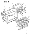
- Figure 1 is a perspective view of an HVAC system
- Figure 2 is a cross-sectional view of an HVAC system including a cross-sectional view of the film valve assembly
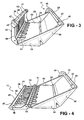
- Figure 3 is a perspective view of a film in a film valve assembly in a first position
- Figure 4 is a perspective view of the film valve assembly of Figure 3 in a second position
- Figure 5 is a fragmented perspective view of the film valve assembly having an actuator disposed in a spaced relationship
- Figure 6 is a fragmented perspective view of a roller
- Figure 7 is a fragmented perspective view of the roller and a cap
- Figure 8 is a fragmented perspective view of the film and the roller installed in the film valve assembly
- Figure 9a is a cross-sectional view of the film in accordance with the subject invention.
- Figure 9b is a cross-sectional view of the film including an optional binder layer.
- HVAC heating, ventilation, and air conditioning system
- the HVAC system 10 generally defines a housing 11 that defines an air inlet 15 and an air outlet 66 .
- the housing 11 includes a film valve assembly 17 that defines at least one aperture 12 , as shown in Figure 2.
- the housing 11 defines a mixing chamber 18 therein.
- the HVAC system 10 includes an evaporator assembly 13 coupled to the housing 11 .
- the HVAC system 10 also includes a heater assembly 14 coupled to the evaporator assembly 13 and the housing 11 .
- the HVAC system 10 further includes control surfaces 58a, 58b disposed in the housing 11 that are moveable for controlling air flow.
- the HVAC system 10 includes a fan assembly 16 disposed on the air inlet 15 .
- the evaporator assembly 13 and heater assembly 14 respectively include an evaporator core 19 and a heater core 20 enclosed within the housing 11 . Additionally, the air inlet 15 defines a passageway 21 having a cavity 22 at an end 23 thereof. The air inlet 15 further includes the fan assembly 16 having a fan 24 disposed in a fan housing 25 .
- the evaporator core 19 is operatively controlled with the HVAC system 10 , and the heater core 20 regulates air temperature.
- the evaporator core 19 extends across an entire width of the housing 11 such that all air passes therethrough.
- the heater core 20 conversely, extends along an edge 43 of the housing 11 .
- control surface 58a is shown as a door.
- the control surface 58a may direct the air to flow around the heater core 20 .
- Air directed by the control surface 58a around the heater core 20 flows up a back face of the heater core 20 and into the air mixing chamber 18 .
- un-heated air that passed solely through the evaporator core 19 is mixed with the air directed around the heater core 20 to achieve a desired temperature.
- the air then flows out of the mixing chamber 18 to the air outlet 66 , as selected by an operator.
- the control surface 58b can be further defined as a film 63 housed within the film valve assembly 17.
- the film 63 is suspended across at least one aperture 12 thus covering the air-mixing chamber 18.
- the film 63 can be moved across at least one aperture 12 with rollers, pulleys, cords, or gears, and the like.
- the film 63 defines openings 31 .
- the openings 31 align with the air outlet 66 such that air can flow out through the air outlet 66 .
- the openings 31 in the film 63 actually align with the at least one aperture 12 that is defined by the film valve assembly 17, which, as introduced above, is a component of the air outlet 66 .
- the openings 31 defined by the film 63 are at least partially aligned with at least one aperture 12, air can pass from the mixing chamber 18 through the film 63 and through the at least one aperture 12 .
- the film valve assembly 17 generally includes a frame 26 .
- the frame 26 includes first 53 , second 54 , and third 56 segments.
- the frame 26 also includes a slot 49 which receives a cap 48 disposed on the frame 26 .
- the cap 48 includes an alignment rib 32 that snaps into the slot 49 .
- the frame 26 may include additional slots 49 and the cap 48 may include additional alignment ribs 32 matching the number of slots 49 .
- the cap 48 may include a fastener 50 for further securing the cap 48 to the frame 26 .
- the frame 26 also includes first and second rollers 27, 28 .
- the film 63 has a first end 29 disposed on the first roller 27 and a second end 30 disposed on the second roller 28 with the film 63 extending therebetween.
- the first and second rollers 27, 28 are disposed on opposite ends 46, 47 of the frame 26 with the first and second ends 29, 30 of the film 63 coupled thereto.
- the film 63 may be supported and kept under tension by one or more idle rollers 33 rotatably supported on the frame 26 .
- the first roller 27 also includes a first biasing device 40 .
- the first biasing device 40 continually urges the first roller 27 to rotate in a first direction under a first constantly applied force.
- the second roller 28 includes a second biasing device 41 .
- the second biasing device 41 continually urges the second roller 28 to rotate in a second direction under a second constantly applied force.
- the first 40 and second 41 biasing devices may be torsion springs, helical torsion springs or any other suitable members that provide torsional force.
- an actuator 57 is coupled to the second roller 28 thereby providing a non-constant rotational torque.
- the actuator 57 may be a stepper motor, a direct current motor and gears, or any suitable actuator.
- the actuator 57 includes a rotatable connector 51 that interfaces the actuator 57 with the second roller 28 in female/male engagement.
- the actuator 57 transfers a positive rotational torque to the second roller 28 .
- a second actuator 57 may be coupled to the first roller 27 .
- the first roller 27 is made from metal, plastic, or any other suitable material.
- the first roller 27 includes a cylinder 37 that is also made from metal, plastic, or any other suitable material.
- the cylinder 37 includes a hollow end 38 that accepts the first biasing device 40.
- the cylinder 37 also includes a beveled end 39 that accepts an axle 34 .
- the axle 34 includes a flattened distal end 35 .
- the flattened distal end 35 interfaces with the frame 26 to ensure that the axle 34 does not rotate.
- the cylinder 37 also includes a second end 36 extending from the hollow end 38 .
- the cylinder 37 includes a locking rib 44 .
- the first roller 27 further includes a shaft 42 that is made from metal, plastic, or any other suitable material.
- the shaft 42 defines a groove 45 and is disposed annularly about the first biasing device 40 and the cylinder 37 . This allows the locking rib 44 to slide into a groove 45 .
- the film 63 of the HVAC system 10 includes a substrate 61 .
- the film 63 is moveable over the frame 26 between open and closed positions for controlling the air flow through the housing 11 .
- the substrate 61 includes a fiber 52 selected from the group of polyester-based fibers, glass-based fibers, and combinations thereof.
- a fluoropolymer layer 62 is disposed on a first face 64 of the substrate 61 and may include, but is not limited to, a perfluoropolymer such as polytetrafluoroethylene.
- the fluoropolymer layer 62 also includes an additive to make the fluoropolymer layer 62 non-electrically charging.
- An elastomeric layer 59 is disposed on a second face 65 of the substrate 61 .
- a silicone topcoat layer 60 is disposed on the elastomeric layer 59.
- the silicone topcoat layer 60 has a thickness of from 0,005 - 0,018 mm (0.2 to 0.7 mils), and more preferably has a thickness of from 0,008 - 0,013 mm (0.3-0.5 mils).
- the silicone topcoat layer 60 minimizes the noise created as the substrate of the film moves between the open and closed positions in the housing 11 of the HVAC system 10 .
- the fluoropolymer layer 62 is disposed on the first and second faces 64, 65 of the substrate 61 and may include, but is not limited to, a perfluoropolymer such as polytetrafluoroethylene.
- the fluoropolymer layer 62 also includes an additive to make the fluoropolymer layer 62 non-electrically charging.
- a mixture of a colloidal silica dispersion and a perfluorinated copolymer resin dispersion 68 is disposed on a face 67 of the fluoropolymer layer 62.
- An elastomeric layer 59 is disposed on the mixture of the colloidal silica dispersion and the perfluorinated copolymer resin dispersion 68 .
- a silicone topcoat layer 60 is disposed on the elastomeric layer 59 . The silicone topcoat layer 60 minimizes the noise created as the substrate of the film moves between the open and closed positions in the housing 11 of the HVAC system 10 .
- the substrate 61 includes, but is not limited to, an industry standard 1080 style fiberglass.
- the substrate 61 includes, but is not limited to, a polyester woven fabric created from yarns between 4,44 - 22,2 tex (40 and 200 denien).
- nylon-based fibers are not included in the substrate due to the nylon-fibers' ability to absorb water and freeze.
- the additive includes carbon black, graphite, metallic powder, metallic flakes, and metallic fibers.
- the elastomeric layer 59 includes a silicone rubber. More specifically, the silicone rubber is a platinum catalyzed, solventless, addition-cure, 100 percent solids, liquid silicone rubber composition.
- the liquid silicone rubber is composed of commercially available A and B components that are mixed in a specified ratio, typically 1:1 or 10:1.
- Each component includes vinyl-terminated polydimethylsiloxane polymers and may include fumed silica as a reinforcing filler, and/or extending fillers.
- the A component includes a catalyst and the B component includes a cross-linking agent and an inhibitor. The inhibitor is removed upon application of heat to the liquid silicone rubber, thus effecting a cure.
- the elastomeric layer 59 may incorporate an organic peroxide catalyst.
- the organic peroxide catalyst may be applied from a solvent solution, dried if necessary to remove the solvent solution and heated appropriately to effect a cure.
- the elastomeric layer 59 may incorporate an atmospheric-moisture-activated acetoxy cure system. The acetoxy cure system may be dried if necessary to remove the solvent solution and allowed to remain exposed to moist air sufficiently long to effect a cure.
- the elastomeric layer 59 may include a urethane, instead of the silicone rubber.
- colloidal silica dispersion includes, but is not limited to, Ludox RTM 40, manufactured by DuPont of Wilmington, Delaware.
- perfluorinated copolymer resin dispersion include, but are not limited to, fluorinated ethylene propylene or perfluoroalkoxy-modified tetrafluoroethylene.
- the silicone topcoat layer 60 is formed from a silicone containing composition including a vinyl and methoxy function dimethyl siloxane.
- a silicone containing composition including a vinyl and methoxy function dimethyl siloxane includes, but is not limited to, 3715 manufactured by Dow Coming Inc. of Midland, Michigan.
- a multi-step method is used.
- the substrate 61 is paid off a roll and coated on the first 64 and second side 65 with a fluoropolymer.
- the first 64 and second 65 sides are dipped in a 100 percent solid system of the fluoropolymer to form the fluoropolymer layer 62 .
- the fluoropolymer layer 62 is then wiped and heated sufficiently to sinter or fuse the fluoropolymer.
- the first step is repeated several times in order to apply a desired amount of fluoropolymer to the substrate 61 that is free of cracks and other defects.
- the fluoropolymer layer 62 can be smoothed and consolidated by passing the substrate 61 through a calendar machine (not shown).
- the fluoropolymer layer 62 should be as thin as possible, while sufficient to achieve the desired function. Although a variety of thicknesses of the fluoropolymer layer 62 can be utilized, a thickness from 0,025 - 0,127 mm (1-5 mils) is preferred.
- the side 67 of the fluoropolymer layer is rendered bondable by coating with a mixture of a colloidal silica dispersion and a perfluorinated copolymer resin dispersion 68 .
- the side 67 of the fluoropolymer layer may be rendered bondable by treatment with a mixture of sodium metal, naphthalene, and a glycol ether, or alternately, a mixture of sodium metal and anhydrous ammonia.
- other means for rendering the side 67 of the fluoropolymer layer bondable include, but are not limited to, corona treatment in special atmospheres, chemical and electrochemical treatments, metal sputtering, and vacuum deposition of metals or metal oxides.
- a controlled amount of an elastomeric material is applied to the side 67 of the fluoropolymer layer.
- the elastomeric layer 59 should be as thin as possible, while sufficient to achieve the desired function. Although a variety of thicknesses of the elastomeric layer 59 can be utilized, a thickness from 0,025 - 0,127 mm (2-50 mils) is preferred.
- the elastomeric layer 59 is dipped in a silicone topcoat solution to form the silicone topcoat layer 60 .
- the silicone topcoat layer 60 is wiped to remove excess solution and heated sufficiently to cure. Upon curing, the silicone topcoat layer 60 and the subject invention, is complete.
- control surfaces 58a, 58b can also be defined as air dampers (not shown) within the HVAC system 10 .
- Air dampers may include one or more flow control vanes or blades which are moveable between a fully open position and a fully closed position by a drivetrain including a gearshaft.
- an actuator may be used to electrically control the air damper from a distant location if desired and continuously adjust the closure position in response to an input.
- the air damper may be oriented in any position as dictated by the particular application
Landscapes
- Physics & Mathematics (AREA)
- Thermal Sciences (AREA)
- Engineering & Computer Science (AREA)
- Mechanical Engineering (AREA)
- Laminated Bodies (AREA)
- Air-Conditioning For Vehicles (AREA)
- Air-Flow Control Members (AREA)
Claims (33)
- Système de chauffage, de ventilation et de climatisation d'air (HVAC) comprenant :(A) un logement définissant une entrée d'air et une sortie d'air pour diriger le flux d'air entre ladite entrée et ladite sortie ;(B) une membrane disposée dans ledit logement et mobile entre des positions ouverte et fermée pour commander l'écoulement d'air à travers ledit logement, ladite membrane comprenant ;(1) un substrat comprenant une fibre sélectionnée à partir du groupe de fibres à base de polyester, de fibres à base de verre, et de leurs combinaisons ;(2) une couche d'élastomère disposée sur ledit substrat ; et(3) une couche supérieure de silicone disposée sur ladite couche d'élastomère pour minimiser le bruit créé tandis que ladite membrane se déplace entre lesdites positions ouverte et fermée.
- Système de chauffage, de ventilation et de climatisation d'air selon la revendication 1, dans lequel ladite couche supérieure de silicone est formée à partir d'une composition contenant de la silicone comprenant un diméthyle siloxane à fonction vinyle et méthoxy.
- Système de chauffage, de ventilation et de climatisation d'air selon la revendication 1, dans lequel ladite couche supérieure de silicone a une épaisseur de 0,005 mm à 0,018 mm (0,2 mils et 0,7 mils).
- Système de chauffage, de ventilation et de climatisation d'air selon la revendication 1, dans lequel ladite couche d'élastomère comprend un caoutchouc de silicone.
- Système de chauffage, de ventilation et de climatisation d'air selon la revendication 4, dans lequel ladite couche supérieure de silicone est formée à partir d'une composition contenant de la silicone comprenant un diméthyle siloxane à fonction vinyle et méthoxy.
- Système de chauffage, de ventilation et de climatisation d'air selon la revendication 4, dans lequel ledit caoutchouc de silicone comprend un peroxyde organique formant catalyseur.
- Système de chauffage, de ventilation et de climatisation d'air selon la revendication 1, dans lequel ladite couche d'élastomère comprend un uréthane.
- Système de chauffage, de ventilation et de climatisation d'air selon la revendication 1, dans lequel ladite membrane comprend en outre une couche de fluoropolymère disposée entre ledit substrat et ladite couche d'élastomère.
- Système de chauffage, de ventilation et de climatisation d'air selon la revendication 8, dans lequel la couche de fluoropolymère comprend un perfluoropolymère.
- Système de chauffage, de ventilation et de climatisation d'air selon la revendication 9, dans lequel ledit perfluoropolymère comprend du polytétrafluoroéthylène.
- Système de chauffage, de ventilation et de climatisation d'air selon la revendication 8, dans lequel la couche de fluoropolymère est disposée sur des faces opposées dudit substrat.
- Système de chauffage, de ventilation et de climatisation d'air selon la revendication 8, dans lequel ladite membrane comprend en outre une couche de liant disposée entre ladite couche de fluoropolymère et ladite couche d'élastomère pour rendre ladite couche d'élastomère liante à ladite couche de fluoropolymère.
- Système de chauffage, de ventilation et de climatisation d'air selon la revendication 12, dans lequel ladite couche de liant comprend un mélange de silice et d'une résine de copolymère perfluoré.
- Système de chauffage, de ventilation et de climatisation d'air selon la revendication 12, dans lequel ladite couche de liant a une épaisseur de 0,762 µm à 5,08 µm (0,03 mils à 0,20 mils).
- Système de chauffage, de ventilation et de climatisation d'air selon la revendication 1, comprenant en outre des ouvertures définies dans ladite membrane pour un alignement avec ladite sortie dudit logement.
- Système de chauffage, de ventilation et de climatisation d'air selon la revendication 1, dans lequel ladite fibre comprend des fibres à base de verre tissées.
- Système de chauffage, de ventilation et de climatisation d'air selon la revendication 1, dans lequel ladite fibre comprend des fibres à base de verre non tissées.
- Système de chauffage, de ventilation et de climatisation d'air selon la revendication 1, dans lequel ladite fibre comprend au moins l'une parmi des fibres à base de polyester tissées et des fibres à base de polyester non tissées.
- Système de chauffage, de ventilation et de climatisation d'air selon la revendication 1, dans lequel ladite membrane est logée dans un ensemble de clapet à membrane.
- Système de chauffage, de ventilation et de climatisation d'air selon la revendication 19, dans lequel ledit ensemble de clapet à membrane comprend un châssis définissant au moins une ouverture.
- Système de chauffage, de ventilation et de climatisation d'air selon la revendication 20, dans lequel ledit ensemble de clapet à membrane comprend en outre des premier et deuxième rouleaux supportés à rotation par ledit châssis et disposés à des extrémités opposées dudit châssis.
- Système de chauffage, de ventilation et de climatisation d'air selon la revendication 21, dans lequel ledit ensemble de clapet à membrane comprend en outre un rouleau libre supporté à rotation par ledit châssis et disposé entre lesdits premier et deuxième rouleaux.
- Système de chauffage, de ventilation et de climatisation d'air selon la revendication 21, dans lequel ladite membrane est enroulée et déroulée par rapport aux premier et deuxième rouleaux et suspendu à travers ladite ouverture.
- Système de chauffage, de ventilation et de climatisation d'air selon la revendication 8, comprenant en outre un additif disposé dans ladite couche de fluoropolymère pour rendre la couche de fluoropolymère électriquement non chargée.
- Système de chauffage, de ventilation et de climatisation d'air selon la revendication 24, dans lequel ledit additif est sélectionné à partir du groupe composé de noir de carbone, de graphite, de poudre métallique, de flocons métalliques, de fibres métalliques, et de leurs combinaisons.
- Ensemble de clapet à membrane pour un système de chauffage, de ventilation et de climatisation d'air, ledit ensemble comprenant :(A) un châssis ;(B) des premier et deuxième rouleaux supportés à rotation par ledit châssis et disposés à des extrémités opposées dudit châssis ;(C) un rouleau libre supporté à rotation par ledit châssis et disposé entre lesdits premier et deuxième rouleaux ; et(D) une membrane enroulée et déroulée par rapport auxdits premier et deuxième rouleaux, ladite membrane comprenant ;(1) un substrat comprenant une fibre sélectionnée à partir du groupe de fibres à base de polyester, de fibres à base de verre, et de leurs combinaisons ;(2) une couche d'élastomère disposée sur ledit substrat ; et(3) une couche supérieure de silicone disposée sur ladite couche d'élastomère pour minimiser le bruit créé tandis que ladite membrane est enroulée et déroulée par rapport auxdits premier et deuxième rouleaux.
- Ensemble de clapet à membrane selon la revendication 26, dans lequel ladite couche supérieure de silicone est formée à partir d'une composition contenant de la silicone comprenant un diméthyle siloxane à fonction vinyle et méthoxy.
- Ensemble de clapet à membrane selon la revendication 26, dans lequel ladite couche d'élastomère comprend un caoutchouc de silicone.
- Ensemble de clapet à membrane selon la revendication 26, dans lequel ladite couche d'élastomère comprend un uréthane.
- Ensemble de clapet à membrane selon la revendication 26, dans lequel ladite membrane comprend en outre une couche de fluoropolymère disposée entre ledit substrat et ladite couche d'élastomère.
- Ensemble de clapet à membrane selon la revendication 26, dans lequel ladite fibre comprend des fibres à base de verre tissées.
- Ensemble de clapet à membrane selon la revendication 26, dans lequel ladite fibre comprend des fibres à base de verre non tissées.
- Ensemble de clapet à membrane selon la revendication 26, dans lequel ladite fibre comprend au moins l'une parmi des fibres à base de polyester tissées et des fibres à base de polyester non tissées.
Applications Claiming Priority (5)
| Application Number | Priority Date | Filing Date | Title |
|---|---|---|---|
| US780467 | 1985-09-26 | ||
| US44832103P | 2003-02-18 | 2003-02-18 | |
| US448321P | 2003-02-18 | ||
| US10/780,467 US7238102B2 (en) | 2003-02-18 | 2004-02-17 | Heating, ventilation, and air conditioning system having a film valve and film for controlling air flow |
| PCT/US2004/004769 WO2004074020A2 (fr) | 2003-02-18 | 2004-02-18 | Systeme de chauffage, ventilation et climatisation possedant un clapet a membrane et membrane de regulation de l'ecoulement d'air |
Publications (3)
| Publication Number | Publication Date |
|---|---|
| EP1597122A2 EP1597122A2 (fr) | 2005-11-23 |
| EP1597122A4 EP1597122A4 (fr) | 2007-04-11 |
| EP1597122B1 true EP1597122B1 (fr) | 2007-12-05 |
Family
ID=32853588
Family Applications (1)
| Application Number | Title | Priority Date | Filing Date |
|---|---|---|---|
| EP04712338A Expired - Lifetime EP1597122B1 (fr) | 2003-02-18 | 2004-02-18 | Systeme de chauffage, ventilation et climatisation possedant un clapet a membrane et membrane de regulation de l'ecoulement d'air |
Country Status (6)
| Country | Link |
|---|---|
| US (1) | US7238102B2 (fr) |
| EP (1) | EP1597122B1 (fr) |
| JP (1) | JP2006510548A (fr) |
| AT (1) | ATE380136T1 (fr) |
| DE (1) | DE602004010495T2 (fr) |
| WO (1) | WO2004074020A2 (fr) |
Families Citing this family (11)
| Publication number | Priority date | Publication date | Assignee | Title |
|---|---|---|---|---|
| US7927684B2 (en) * | 2000-01-19 | 2011-04-19 | Saint-Gobain Performance Plastics Corporation | Low coefficient of friction polymer film |
| US20070270094A1 (en) * | 2006-05-19 | 2007-11-22 | Chun-Shung Liang | Film valve assembly for a heating, ventilation, and air conditioning system |
| USD577110S1 (en) * | 2007-05-21 | 2008-09-16 | Mcdonald Michael | Air cleaner |
| US7637031B2 (en) * | 2007-06-26 | 2009-12-29 | Gm Global Technology Operations, Inc. | Evaporator core drying system |
| KR101511513B1 (ko) * | 2007-10-09 | 2015-04-13 | 한라비스테온공조 주식회사 | 차량 공조장치용 도어 |
| MX2011006681A (es) * | 2008-12-22 | 2011-07-12 | Saint Gobain Performance Plast | Material de lamina de perfluoropolimero modificado y metodos para su preparacion. |
| JP5863303B2 (ja) * | 2011-07-13 | 2016-02-16 | 三菱重工業株式会社 | 車両用空調装置 |
| CN109844044B (zh) | 2016-10-24 | 2021-12-10 | 美国圣戈班性能塑料公司 | 聚合物组合物、材料和制备方法 |
| WO2019003611A1 (fr) * | 2017-06-29 | 2019-01-03 | 日本精工株式会社 | Dispositif oscillant, dispositif de super-finition, procédé de fabrication de palier d'arbre, procédé de fabrication de véhicule, procédé de fabrication de machine |
| JP6915460B2 (ja) | 2017-08-30 | 2021-08-04 | 株式会社デンソー | 空調ユニット |
| WO2022207838A1 (fr) * | 2021-03-31 | 2022-10-06 | Valeo Systemes Thermiques | Dispositif de traitement thermique d'air pour véhicule a gestion de temperature améliorée |
Family Cites Families (30)
| Publication number | Priority date | Publication date | Assignee | Title |
|---|---|---|---|---|
| US3521653A (en) * | 1967-12-13 | 1970-07-28 | Sperry Rand Corp | Power transmission |
| US3870593A (en) * | 1972-06-06 | 1975-03-11 | Minnesota Mining & Mfg | Stretch-oriented porous films and preparation and use thereof |
| US4715912A (en) * | 1977-03-30 | 1987-12-29 | Tillotson John G | Method for forming a layer of blown cellular urethane on a carpet backing |
| US4725279A (en) * | 1979-01-22 | 1988-02-16 | Sterling Drug Inc. | Bio compatible and blood compatible materials and methods |
| US5230937A (en) * | 1983-04-13 | 1993-07-27 | Chemfab Corporation | Reinforced fluoropolymer composite |
| DE3323176C2 (de) * | 1983-06-28 | 1989-04-27 | Adam Opel AG, 6090 Rüsselsheim | Heiz- und Belüftungseinrichtung für den Fahrgastraum von Kraftfahrzeugen |
| US4773310A (en) * | 1986-12-01 | 1988-09-27 | Howard Corwin | Fan ventilator having multiple modes of operation |
| US5192609A (en) * | 1988-11-07 | 1993-03-09 | Eastman Kodak Company | Thermoformable sheet material |
| US5118372A (en) * | 1988-11-21 | 1992-06-02 | Eastman Kodak Company | Method of forming a protective and decorative sheet material on a substrate |
| EP0545320B1 (fr) * | 1991-11-29 | 1997-01-29 | Nippondenso Co., Ltd. | Dispositif de commutation de passage d'air |
| US5217797A (en) * | 1992-02-19 | 1993-06-08 | W. L. Gore & Associates, Inc. | Chemically resistant diaphragm |
| US5653630A (en) * | 1994-10-07 | 1997-08-05 | Nippondenso Co., Ltd. | Air conditioning apparatus with film door |
| JP3692572B2 (ja) * | 1995-10-12 | 2005-09-07 | 株式会社デンソー | 空調装置 |
| JP3493093B2 (ja) * | 1996-02-16 | 2004-02-03 | 本田技研工業株式会社 | 車両用空調装置のダンパ機構 |
| US6168751B1 (en) * | 1997-10-28 | 2001-01-02 | Ames Rubber Corporation | Method of making multilayer rolls having a thin fluoropolymer top coat |
| JP4013315B2 (ja) * | 1998-03-11 | 2007-11-28 | 株式会社デンソー | 車両用空調装置 |
| US5964658A (en) * | 1998-03-31 | 1999-10-12 | Denso Corporation | Air passage opening/closing system for air conditioning apparatus |
| US5885152A (en) * | 1998-04-20 | 1999-03-23 | General Motors Corporation | Automotive ventilation housing with self supporting film valve having a convex semi-cylindrical shape |
| US6045444A (en) * | 1998-08-28 | 2000-04-04 | General Motors Corporation | Compact automotive air conditioning module |
| US6296562B1 (en) * | 1998-09-08 | 2001-10-02 | Denso Corporation | Air passage switching device and air conditioning apparatus having the same |
| JP4396013B2 (ja) * | 1999-11-11 | 2010-01-13 | 株式会社デンソー | 空気通路開閉装置 |
| US6352150B1 (en) * | 2000-01-10 | 2002-03-05 | William J. Lewis | Coated endless belt |
| US6926068B2 (en) * | 2000-01-13 | 2005-08-09 | Denso Corporation | Air passage switching device and vehicle air conditioner |
| US6930063B2 (en) * | 2000-01-19 | 2005-08-16 | Saint-Gobain Performance Plastics Corporation | Non-curling reinforced composite membranes with differing opposed faces, methods for producing and their use in varied applications |
| US6482884B1 (en) * | 2000-02-28 | 2002-11-19 | Pirelli Pneumatici S.P.A. | Silica reinforced rubber compositions of improved processability and storage stability |
| US6383959B1 (en) | 2000-03-23 | 2002-05-07 | Milliken & Company | Fabric for diverting air flow in an automotive air conditioning system |
| US6616060B2 (en) * | 2001-10-11 | 2003-09-09 | Delphi Technologies, Inc. | Flexible film cartridge with balanced effort |
| US6905985B1 (en) * | 2002-11-21 | 2005-06-14 | Highland Industries, Inc. | Fabric film for automotive heaters |
| JP4093031B2 (ja) * | 2002-11-28 | 2008-05-28 | 株式会社デンソー | 流体通路制御装置 |
| US6932691B1 (en) * | 2004-05-28 | 2005-08-23 | Macauto Industrial Co., Ltd. | Film valve assembly for a heating, ventilation and air conditioning system |
-
2004
- 2004-02-17 US US10/780,467 patent/US7238102B2/en not_active Expired - Lifetime
- 2004-02-18 EP EP04712338A patent/EP1597122B1/fr not_active Expired - Lifetime
- 2004-02-18 JP JP2005518230A patent/JP2006510548A/ja active Pending
- 2004-02-18 WO PCT/US2004/004769 patent/WO2004074020A2/fr not_active Ceased
- 2004-02-18 AT AT04712338T patent/ATE380136T1/de not_active IP Right Cessation
- 2004-02-18 DE DE602004010495T patent/DE602004010495T2/de not_active Expired - Lifetime
Also Published As
| Publication number | Publication date |
|---|---|
| WO2004074020A3 (fr) | 2005-05-06 |
| DE602004010495D1 (de) | 2008-01-17 |
| ATE380136T1 (de) | 2007-12-15 |
| WO2004074020A2 (fr) | 2004-09-02 |
| US20040159420A1 (en) | 2004-08-19 |
| JP2006510548A (ja) | 2006-03-30 |
| US7238102B2 (en) | 2007-07-03 |
| DE602004010495T2 (de) | 2008-11-13 |
| EP1597122A4 (fr) | 2007-04-11 |
| EP1597122A2 (fr) | 2005-11-23 |
Similar Documents
| Publication | Publication Date | Title |
|---|---|---|
| EP1597122B1 (fr) | Systeme de chauffage, ventilation et climatisation possedant un clapet a membrane et membrane de regulation de l'ecoulement d'air | |
| US7927684B2 (en) | Low coefficient of friction polymer film | |
| US5326315A (en) | Air passage changeover device | |
| US10174847B2 (en) | Saw tooth design for control damper | |
| JP4409664B2 (ja) | ゴムベルト | |
| JP3663752B2 (ja) | 空気通路切替装置および車両用空調装置 | |
| WO2011125330A1 (fr) | Elément de ventilation | |
| TWI616604B (zh) | 滾珠螺桿、密封材、及密封構造 | |
| CN102449061A (zh) | 改性的全氟聚合物片材料以及制造它的方法 | |
| WO2005021308A1 (fr) | Surface reflechissante destinee a une bande d'etancheite d'un vehicule | |
| CN104441864A (zh) | 多层飞行器遮蔽材料 | |
| US7670215B2 (en) | Control device comprising a roller band cassette | |
| DE10355316B4 (de) | Luftkanal-Umschaltvorrichtung mit Verschlussband | |
| CN111566013B (zh) | 多功能贴面膜 | |
| JP4013830B2 (ja) | 通風路開閉ドアのシール構造 | |
| CN118311824B (zh) | 投影幕布、其制备方法、投影系统及车辆 | |
| US7241215B2 (en) | Fabric valve for vehicle climate control system | |
| AU2003257872A1 (en) | Reinforcing tape comprising a ply of longitudinal high-tenacity yarns | |
| JPH05201234A (ja) | 空気通路切替装置 | |
| JPH07205638A (ja) | 空気通路切替装置 | |
| WO2012141851A1 (fr) | Films de revêtement de surface conducteurs et procédés de production de ceux-ci | |
| JP2003322216A (ja) | 歯付ベルト | |
| JP2002147537A (ja) | 歯付ベルト | |
| US6979258B2 (en) | Point contact valve seats for film applications | |
| JP2000326811A (ja) | コート布の製造方法 |
Legal Events
| Date | Code | Title | Description |
|---|---|---|---|
| PUAI | Public reference made under article 153(3) epc to a published international application that has entered the european phase |
Free format text: ORIGINAL CODE: 0009012 |
|
| AK | Designated contracting states |
Kind code of ref document: A2 Designated state(s): AT BE BG CH CY CZ DE DK EE ES FI FR GB GR HU IE IT LI LU MC NL PT RO SE SI SK TR |
|
| AX | Request for extension of the european patent |
Extension state: AL LT LV MK |
|
| 17P | Request for examination filed |
Effective date: 20051107 |
|
| RBV | Designated contracting states (corrected) |
Designated state(s): AT BE BG CH CY CZ DE DK EE ES FI FR GB GR HU IE IT LI LU MC NL PT RO SE SI SK TR |
|
| RIC1 | Information provided on ipc code assigned before grant |
Ipc: B60S 1/54 20060101AFI20051216BHEP Ipc: B60H 1/30 20060101ALI20051216BHEP |
|
| DAX | Request for extension of the european patent (deleted) | ||
| A4 | Supplementary search report drawn up and despatched |
Effective date: 20070313 |
|
| GRAP | Despatch of communication of intention to grant a patent |
Free format text: ORIGINAL CODE: EPIDOSNIGR1 |
|
| GRAS | Grant fee paid |
Free format text: ORIGINAL CODE: EPIDOSNIGR3 |
|
| GRAA | (expected) grant |
Free format text: ORIGINAL CODE: 0009210 |
|
| AK | Designated contracting states |
Kind code of ref document: B1 Designated state(s): AT BE BG CH CY CZ DE DK EE ES FI FR GB GR HU IE IT LI LU MC NL PT RO SE SI SK TR |
|
| REG | Reference to a national code |
Ref country code: GB Ref legal event code: FG4D |
|
| REG | Reference to a national code |
Ref country code: IE Ref legal event code: FG4D |
|
| REG | Reference to a national code |
Ref country code: CH Ref legal event code: EP |
|
| REF | Corresponds to: |
Ref document number: 602004010495 Country of ref document: DE Date of ref document: 20080117 Kind code of ref document: P |
|
| PG25 | Lapsed in a contracting state [announced via postgrant information from national office to epo] |
Ref country code: CH Free format text: LAPSE BECAUSE OF FAILURE TO SUBMIT A TRANSLATION OF THE DESCRIPTION OR TO PAY THE FEE WITHIN THE PRESCRIBED TIME-LIMIT Effective date: 20071205 Ref country code: LI Free format text: LAPSE BECAUSE OF FAILURE TO SUBMIT A TRANSLATION OF THE DESCRIPTION OR TO PAY THE FEE WITHIN THE PRESCRIBED TIME-LIMIT Effective date: 20071205 Ref country code: ES Free format text: LAPSE BECAUSE OF FAILURE TO SUBMIT A TRANSLATION OF THE DESCRIPTION OR TO PAY THE FEE WITHIN THE PRESCRIBED TIME-LIMIT Effective date: 20080316 Ref country code: SE Free format text: LAPSE BECAUSE OF FAILURE TO SUBMIT A TRANSLATION OF THE DESCRIPTION OR TO PAY THE FEE WITHIN THE PRESCRIBED TIME-LIMIT Effective date: 20080305 Ref country code: NL Free format text: LAPSE BECAUSE OF FAILURE TO SUBMIT A TRANSLATION OF THE DESCRIPTION OR TO PAY THE FEE WITHIN THE PRESCRIBED TIME-LIMIT Effective date: 20071205 |
|
| PG25 | Lapsed in a contracting state [announced via postgrant information from national office to epo] |
Ref country code: SI Free format text: LAPSE BECAUSE OF FAILURE TO SUBMIT A TRANSLATION OF THE DESCRIPTION OR TO PAY THE FEE WITHIN THE PRESCRIBED TIME-LIMIT Effective date: 20071205 Ref country code: FI Free format text: LAPSE BECAUSE OF FAILURE TO SUBMIT A TRANSLATION OF THE DESCRIPTION OR TO PAY THE FEE WITHIN THE PRESCRIBED TIME-LIMIT Effective date: 20071205 |
|
| NLV1 | Nl: lapsed or annulled due to failure to fulfill the requirements of art. 29p and 29m of the patents act | ||
| REG | Reference to a national code |
Ref country code: CH Ref legal event code: PL |
|
| PG25 | Lapsed in a contracting state [announced via postgrant information from national office to epo] |
Ref country code: AT Free format text: LAPSE BECAUSE OF FAILURE TO SUBMIT A TRANSLATION OF THE DESCRIPTION OR TO PAY THE FEE WITHIN THE PRESCRIBED TIME-LIMIT Effective date: 20071205 |
|
| ET | Fr: translation filed | ||
| PG25 | Lapsed in a contracting state [announced via postgrant information from national office to epo] |
Ref country code: CZ Free format text: LAPSE BECAUSE OF FAILURE TO SUBMIT A TRANSLATION OF THE DESCRIPTION OR TO PAY THE FEE WITHIN THE PRESCRIBED TIME-LIMIT Effective date: 20071205 |
|
| PG25 | Lapsed in a contracting state [announced via postgrant information from national office to epo] |
Ref country code: BE Free format text: LAPSE BECAUSE OF FAILURE TO SUBMIT A TRANSLATION OF THE DESCRIPTION OR TO PAY THE FEE WITHIN THE PRESCRIBED TIME-LIMIT Effective date: 20071205 Ref country code: RO Free format text: LAPSE BECAUSE OF FAILURE TO SUBMIT A TRANSLATION OF THE DESCRIPTION OR TO PAY THE FEE WITHIN THE PRESCRIBED TIME-LIMIT Effective date: 20071205 Ref country code: SK Free format text: LAPSE BECAUSE OF FAILURE TO SUBMIT A TRANSLATION OF THE DESCRIPTION OR TO PAY THE FEE WITHIN THE PRESCRIBED TIME-LIMIT Effective date: 20071205 |
|
| PG25 | Lapsed in a contracting state [announced via postgrant information from national office to epo] |
Ref country code: PT Free format text: LAPSE BECAUSE OF FAILURE TO SUBMIT A TRANSLATION OF THE DESCRIPTION OR TO PAY THE FEE WITHIN THE PRESCRIBED TIME-LIMIT Effective date: 20080505 |
|
| PLBE | No opposition filed within time limit |
Free format text: ORIGINAL CODE: 0009261 |
|
| STAA | Information on the status of an ep patent application or granted ep patent |
Free format text: STATUS: NO OPPOSITION FILED WITHIN TIME LIMIT |
|
| PG25 | Lapsed in a contracting state [announced via postgrant information from national office to epo] |
Ref country code: MC Free format text: LAPSE BECAUSE OF NON-PAYMENT OF DUE FEES Effective date: 20080228 Ref country code: DK Free format text: LAPSE BECAUSE OF FAILURE TO SUBMIT A TRANSLATION OF THE DESCRIPTION OR TO PAY THE FEE WITHIN THE PRESCRIBED TIME-LIMIT Effective date: 20071205 |
|
| 26N | No opposition filed |
Effective date: 20080908 |
|
| GBPC | Gb: european patent ceased through non-payment of renewal fee |
Effective date: 20080305 |
|
| PG25 | Lapsed in a contracting state [announced via postgrant information from national office to epo] |
Ref country code: GR Free format text: LAPSE BECAUSE OF FAILURE TO SUBMIT A TRANSLATION OF THE DESCRIPTION OR TO PAY THE FEE WITHIN THE PRESCRIBED TIME-LIMIT Effective date: 20080306 Ref country code: EE Free format text: LAPSE BECAUSE OF FAILURE TO SUBMIT A TRANSLATION OF THE DESCRIPTION OR TO PAY THE FEE WITHIN THE PRESCRIBED TIME-LIMIT Effective date: 20071205 Ref country code: IE Free format text: LAPSE BECAUSE OF NON-PAYMENT OF DUE FEES Effective date: 20080218 |
|
| PG25 | Lapsed in a contracting state [announced via postgrant information from national office to epo] |
Ref country code: BG Free format text: LAPSE BECAUSE OF FAILURE TO SUBMIT A TRANSLATION OF THE DESCRIPTION OR TO PAY THE FEE WITHIN THE PRESCRIBED TIME-LIMIT Effective date: 20080305 |
|
| PG25 | Lapsed in a contracting state [announced via postgrant information from national office to epo] |
Ref country code: GB Free format text: LAPSE BECAUSE OF NON-PAYMENT OF DUE FEES Effective date: 20080305 |
|
| PG25 | Lapsed in a contracting state [announced via postgrant information from national office to epo] |
Ref country code: CY Free format text: LAPSE BECAUSE OF FAILURE TO SUBMIT A TRANSLATION OF THE DESCRIPTION OR TO PAY THE FEE WITHIN THE PRESCRIBED TIME-LIMIT Effective date: 20071205 |
|
| PG25 | Lapsed in a contracting state [announced via postgrant information from national office to epo] |
Ref country code: HU Free format text: LAPSE BECAUSE OF FAILURE TO SUBMIT A TRANSLATION OF THE DESCRIPTION OR TO PAY THE FEE WITHIN THE PRESCRIBED TIME-LIMIT Effective date: 20080606 Ref country code: LU Free format text: LAPSE BECAUSE OF NON-PAYMENT OF DUE FEES Effective date: 20080218 |
|
| PG25 | Lapsed in a contracting state [announced via postgrant information from national office to epo] |
Ref country code: TR Free format text: LAPSE BECAUSE OF FAILURE TO SUBMIT A TRANSLATION OF THE DESCRIPTION OR TO PAY THE FEE WITHIN THE PRESCRIBED TIME-LIMIT Effective date: 20071205 |
|
| PG25 | Lapsed in a contracting state [announced via postgrant information from national office to epo] |
Ref country code: IT Free format text: LAPSE BECAUSE OF NON-PAYMENT OF DUE FEES Effective date: 20080229 |
|
| REG | Reference to a national code |
Ref country code: DE Ref legal event code: R082 Ref document number: 602004010495 Country of ref document: DE Representative=s name: BRP RENAUD UND PARTNER MBB RECHTSANWAELTE PATE, DE Ref country code: DE Ref legal event code: R082 Ref document number: 602004010495 Country of ref document: DE Representative=s name: BRP RENAUD UND PARTNER MBB, DE Ref country code: DE Ref legal event code: R081 Ref document number: 602004010495 Country of ref document: DE Owner name: MAHLE INTERNATIONAL GMBH, DE Free format text: FORMER OWNER: DELPHI TECHNOLOGIES, INC., TROY, MICH., US |
|
| REG | Reference to a national code |
Ref country code: FR Ref legal event code: PLFP Year of fee payment: 13 |
|
| REG | Reference to a national code |
Ref country code: FR Ref legal event code: PLFP Year of fee payment: 14 |
|
| REG | Reference to a national code |
Ref country code: FR Ref legal event code: TP Owner name: MAHLE INTERNATIONAL GMBH, DE Effective date: 20180103 |
|
| REG | Reference to a national code |
Ref country code: FR Ref legal event code: PLFP Year of fee payment: 15 |
|
| PGFP | Annual fee paid to national office [announced via postgrant information from national office to epo] |
Ref country code: DE Payment date: 20190430 Year of fee payment: 16 |
|
| PGFP | Annual fee paid to national office [announced via postgrant information from national office to epo] |
Ref country code: FR Payment date: 20200225 Year of fee payment: 17 |
|
| REG | Reference to a national code |
Ref country code: DE Ref legal event code: R119 Ref document number: 602004010495 Country of ref document: DE |
|
| PG25 | Lapsed in a contracting state [announced via postgrant information from national office to epo] |
Ref country code: DE Free format text: LAPSE BECAUSE OF NON-PAYMENT OF DUE FEES Effective date: 20200901 |
|
| PG25 | Lapsed in a contracting state [announced via postgrant information from national office to epo] |
Ref country code: FR Free format text: LAPSE BECAUSE OF NON-PAYMENT OF DUE FEES Effective date: 20210228 |