EP1596158B1 - Dispositif pour déterminer la forme d'un objet en trois dimensions - Google Patents
Dispositif pour déterminer la forme d'un objet en trois dimensions Download PDFInfo
- Publication number
- EP1596158B1 EP1596158B1 EP05009321A EP05009321A EP1596158B1 EP 1596158 B1 EP1596158 B1 EP 1596158B1 EP 05009321 A EP05009321 A EP 05009321A EP 05009321 A EP05009321 A EP 05009321A EP 1596158 B1 EP1596158 B1 EP 1596158B1
- Authority
- EP
- European Patent Office
- Prior art keywords
- light
- parameter
- areas
- dimensional
- computing
- Prior art date
- Legal status (The legal status is an assumption and is not a legal conclusion. Google has not performed a legal analysis and makes no representation as to the accuracy of the status listed.)
- Not-in-force
Links
- 238000000034 method Methods 0.000 claims description 69
- 238000003384 imaging method Methods 0.000 claims description 61
- 230000003287 optical effect Effects 0.000 claims description 27
- 238000001514 detection method Methods 0.000 claims description 18
- 230000008569 process Effects 0.000 description 37
- 230000015654 memory Effects 0.000 description 27
- 238000005070 sampling Methods 0.000 description 18
- 238000005259 measurement Methods 0.000 description 17
- 230000004075 alteration Effects 0.000 description 11
- 238000004364 calculation method Methods 0.000 description 8
- 238000012937 correction Methods 0.000 description 7
- 230000006870 function Effects 0.000 description 5
- 239000004065 semiconductor Substances 0.000 description 5
- 238000006243 chemical reaction Methods 0.000 description 3
- 230000002123 temporal effect Effects 0.000 description 3
- 238000004891 communication Methods 0.000 description 2
- 238000010586 diagram Methods 0.000 description 2
- 239000004973 liquid crystal related substance Substances 0.000 description 2
- 230000002093 peripheral effect Effects 0.000 description 2
- 238000012545 processing Methods 0.000 description 2
- 238000005452 bending Methods 0.000 description 1
- 238000007796 conventional method Methods 0.000 description 1
- 238000012888 cubic function Methods 0.000 description 1
- 238000003780 insertion Methods 0.000 description 1
- 230000037431 insertion Effects 0.000 description 1
- 238000012067 mathematical method Methods 0.000 description 1
- 230000007246 mechanism Effects 0.000 description 1
- 238000012986 modification Methods 0.000 description 1
- 230000004048 modification Effects 0.000 description 1
- 238000012544 monitoring process Methods 0.000 description 1
- 230000010355 oscillation Effects 0.000 description 1
- 239000007787 solid Substances 0.000 description 1
- 238000007619 statistical method Methods 0.000 description 1
- 230000009466 transformation Effects 0.000 description 1
- 239000002699 waste material Substances 0.000 description 1
Images


Classifications
-
- G—PHYSICS
- G01—MEASURING; TESTING
- G01B—MEASURING LENGTH, THICKNESS OR SIMILAR LINEAR DIMENSIONS; MEASURING ANGLES; MEASURING AREAS; MEASURING IRREGULARITIES OF SURFACES OR CONTOURS
- G01B11/00—Measuring arrangements characterised by the use of optical techniques
- G01B11/24—Measuring arrangements characterised by the use of optical techniques for measuring contours or curvatures
- G01B11/25—Measuring arrangements characterised by the use of optical techniques for measuring contours or curvatures by projecting a pattern, e.g. one or more lines, moiré fringes on the object
- G01B11/2518—Projection by scanning of the object
Definitions
- the present invention relates to a three-dimensional shape input device for measuring a three-dimensional shape of an object in a noncontact manner by a light projection method and entering the measurement result. More specifically, the present invention relates to a device that computes the three-dimensional shape by using an optimal parameter for each sectioned imaging area on an imaging surface.
- a noncontact type three-dimensional shape input device In order to enter three-dimensional shape data of an object, a noncontact type three-dimensional shape input device is often used. This device projects detection light onto the object and receives reflected light from the object by an image sensor. This method is called a light projection method.
- slit light projection method also called a light-section method
- slit light having a slit-like cross section is used as the detection light that is projected, and the slit light is deflected so as to scan the object optically (see U.S. Patent No. 6,141,105 ).
- Figs. 18(a)-18(d) show a general outline of the slit light projection method
- Figs. 19(a)-19(c) show a principle of measurement by the slit light projection method.
- slit light U is projected onto an object Q, and reflected light from the object Q enters the imaging surface S2 of the image sensor (Fig. 18(a)). If an irradiated part of the object Q is flat, an obtained image (a slit image) is a straight line (Fig. 18(b)). If the irradiated part has pits and projections, the line becomes a curved or step-like shape (Fig. 18(c)). Namely, a distance between the measuring device and the object Q is reflected in an incident position of the reflected light on the imaging surface S2 (Fig. 18(d)). When deflecting the slit light U in its width direction (the vertical direction in Fig. 18), the surface of the object Q is scanned so that sampling of three-dimensional positions is performed.
- a light projecting system and a light receiving system are positioned so that a base line AO that links a starting point A of the emitted light and a principal point O of a lens of the light receiving system becomes perpendicular to a light reception axis.
- the light reception axis is perpendicular to the imaging surface S2.
- the principal point of a lens is a point (a rear principal point) that is away from the imaging surface S2 by an image distance b on the light reception axis when an image of a subject at a finite distance is formed on the imaging surface S2.
- the image distance b may be referred to as an effective focal distance Freal.
- the principal point O is regarded as the origin of a three-dimensional rectangular coordinate system.
- the light reception axis is the Z axis
- the base line AO is the Y axis
- a lengthwise direction of the slit light is the X axis.
- ⁇ a represents an angle between a light projection axis and a light projection reference plane (a light projection plane that is parallel with the light reception axis)
- ⁇ p represents an acceptance angle when the slit light U is projected onto a point P(X,Y,Z) on the object.
- the coordinate Z of the point P can be expressed by the equation (1).
- the acceptance angle ⁇ p is the angle between the line that links the point P and the principal point O and a plane that includes the light reception axis (a light reception axis plane).
- the angle ⁇ a can be derived from an angular velocity of deflection of the slit light U.
- the acceptance angle ⁇ p can be derived from the relationship of the equation below.
- the three-dimensional position of the point P can be determined in accordance with the angle ⁇ a.
- the three-dimensional shape data according to the light projection method can be calculated relatively easily by using various parameters including camera parameters and light projecting optical system parameters and by applying a camera sight line equation and a detection light plane equation.
- the principal point O is divided into a front principal point H and a rear principal point H' as shown in Fig. 19(c).
- Japanese Patent No. 2913021 discloses a device for entering three-dimensional shape data of an object by a pattern projection method. According to the method, space coordinates on the surface of an object Q is calculated from an image of a two-dimensional grid that is drawn on a reference plane, an image of a two-dimensional grid that is projected onto the reference plane, a three-dimensional image on the reference plane, and an image of a two-dimensional grid that is projected onto the object Q.
- the three-dimensional shape data are calculated on the assumption that the cross section of the slit light is linear, namely, the slit light is a complete plane.
- an optical shape distortion occurs due to an aberration of a lens.
- a shape distortion occurs in the slit light due to an aberration of a lens in the light projecting optical system.
- an image on the imaging surface S2 is distorted due to an aberration of a lens in the light receiving optical system.
- the distortion may often occur at a peripheral portion of the imaging surface S2.
- a laser beam that is projected from a semiconductor laser that is used as a light source is not a complete ellipse, and a cylindrical lens has an aberration. Therefore, the slit light becomes not a flat plane but a curved surface after the laser beam passes through the cylindrical lens.
- This problem occurs not only in the slit light projection method but also in other various light projection methods that project spot light, step light or pattern light.
- the device disclosed in the Japanese Patent No. 2913021 uses an image of a reference object for each pixel of the image sensor directly for calculating coordinates. As it does not use an optical system parameter, an error due to the parameter does not occur. But, in order to determine three-dimensional shape data with high degree of precision, it is necessary to project plural types of two-dimensional grid patterns and to determine a phase in each direction at high degree of precision by using a pattern coding method or a Fourier transformation phase shifting method. In addition, it is also necessary to draw the two-dimensional grid in different phases on the reference plane so as to determine phases in each direction precisely. Therefore, there is a tendency that the structure or contents of processes of devices become complicated or large scaled, and it is disadvantageous in cost.
- a three-dimensional shape input device for entering a three-dimensional shape of an object by a light projection method.
- the device includes a light projecting portion for projecting detection light onto an object, an imaging portion for receiving reflected light from the object, a storage portion for storing a parameter that is used for computing the three-dimensional shape, a computing portion for computing and determining the three-dimensional shape of the object by using image data delivered from the imaging portion and the parameter, a dividing portion for dividing an imaging surface of an image sensor into plural areas.
- the storage portion stores plural parameters that are used for the plural areas, respectively.
- the computing portion computes and determines the three-dimensional shape for each area by using a parameter to be used for each area.
- the computing portion performs the computation by using a camera sight line equation and a detection light plane equation.
- the computing portion performs the computation for each of the areas by using a parameter to be applied to each of the areas as a camera parameter that is used for the camera sight line equation.
- the computing portion performs the computation for each of the areas by using a parameter to be applied to each of the areas as a light projecting optical system parameter that is used for the detection light plane equation.
- the light projecting portion projects fixed slit light as the detection light.
- the light projecting portion scans the object by deflecting projected slit light
- the computing portion performs the computation by using a parameter to be applied to each of the areas that includes an angular velocity parameter of a deflecting mirror for deflecting the slit light.
- the light projecting portion projects stripe pattern light as the detection light.
- the parameter is used that is interpolated so that a value of the parameter becomes continuous at a boundary of the areas.
- Fig. 1 shows a measuring system 1 according to an embodiment of the present invention.
- the measuring system 1 includes a three-dimensional camera 2 that performs three-dimensional measurement by a slit light projection method and a host computer 3 for processing output data of the three-dimensional camera 2.
- the three-dimensional camera 2 outputs measured data (slit image data) for specifying three-dimensional positions of plural sampling points on an object Q as well as a two-dimensional image that indicates color information of the object Q, a parameter that is necessary for computing a three-dimensional position of the sampling point, data that are necessary for calibration and others.
- the host computer 3 uses the data and the parameter so as to calculate and determine the three-dimensional position of the sampling point, i.e., three-dimensional coordinates by applying a triangulation method. When the three-dimensional coordinates are computed, a camera sight line equation, a detection light plane equation and the like are applied.
- the host computer 3 is a computer system including a CPU 3a, a display device 3b, a keyboard 3c and a mouse 3d.
- the CPU 3a is equipped with memories including a ROM and a RAM, and software is installed in the memories for a process of the measured data.
- a memory of the CPU 3a stores parameters that are used for computation of the three-dimensional coordinates that will be described later and various computing equations.
- data can be communicated on line and off line by using a portable recording medium 4.
- a magneto-optical disk, a memory chip or the like can be used.
- Figs. 2(a) and 2(b) are perspective views showing an external appearance of the three-dimensional camera 2.
- the three-dimensional camera 2 includes a housing 20 having a substantially rectangular solid shape that houses an optical unit OU.
- the housing 20 is provided with a light projecting window 20a and a light receiving window 20b at the front face.
- the light projecting window 20a is disposed at a position a predetermined distance away from the upper side of the light receiving window 20b.
- the optical unit OU emits slit light U that is a laser beam extending in the horizontal direction.
- the slit light U is plane-like light extending in the horizontal direction by an irradiation angle ⁇ and having a width w in the vertical direction.
- a length M1 in the horizontal direction of the slit light U varies in accordance with a distance from the light projecting window 20a.
- the shape and the angle of the slit light U are distorted due to various factors as being described later, so the slit light U is not an ideal plane as a matter of fact but has distortions, for example.
- the slit light U is directed to the object (subject) Q to be measured.
- the slit light U is reflected by the surface of the object Q, and a part of it enters the optical unit OU through the light receiving window 20b.
- the optical unit OU has a biaxial adjustment mechanism for adjusting a relationship between a light projection axis and a light reception axis.
- the upper face of the housing 20 is provided with zooming buttons 25a and 25b, manual focusing buttons 26a and 26b, and a shutter button 27.
- the rear face of the housing 20 is provided with a liquid crystal display (LCD) 21, a cursor button 22, a selection button 23, a cancellation button 24, analog output terminals 31 and 32, a digital output terminal 33, and an insertion slot 30a for the recording medium 4.
- LCD liquid crystal display
- the liquid crystal display 21 is used for displaying operational screens and as an electronic finder. A user can set a shooting mode by using the buttons 21-24 on the rear face.
- the measured data are delivered via the analog output terminal 31, and the two-dimensional image signal is delivered via the analog output terminal 31.
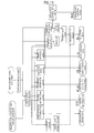
- Fig. 3 is a block diagram showing a functional structure of the three-dimensional camera 2.
- a solid line with an arrow indicates a flow of an electric signal, while a broken line with an arrow indicates a flow of light.
- the three-dimensional camera 2 includes two optical systems 40 and 50 of a light projecting side and a light receiving side, which constitute the above-mentioned optical unit OU.
- a laser beam having the wavelength of 690 nm emitted by a semiconductor laser (LD) 41 passes through a light projecting lens system 42 to be the slit light U and is deflected by a galvanomirror 43 that is scanning means.
- a driver 44 of the semiconductor laser 41, a driving system 45 of the light projecting lens system 42 and a driving system 46 of the galvanomirror 43 are controlled by a system controller 61.
- a zoom unit 51 In the optical system 50, light condensed by a zoom unit 51 is divided by a beam splitter 52. Light having a wavelength within an oscillation wavelength range of the semiconductor laser 41 enters an image sensor 53 that is a measuring image sensor. Light having a wavelength within a visible range enters a color image sensor 54 for monitoring. Each of the image sensor 53 and the color image sensor 54 is an area sensor including a CCD.
- the zoom unit 51 is an internal focusing type, in which incident light is partially used for automatic focus (AF).
- the AF function is realized by an AF sensor 57, a lens controller 58 and a focus driving system 59.
- a zoom driving system 60 is provided for electric zooming.
- Imaging information of the image sensor 53 is transmitted to an output process circuit 62 in synchronization with a clock from a driver 55.
- the output process circuit 62 generates measured data corresponding to pixels of the image sensor 53, and the measured data are stored in a memory 63.
- the imaging surface S2 of the image sensor 53 is divided (sectioned) into plural areas ER, and measured data of each pixel are discriminated for each sectioned area. Namely, each of the measured data includes area division information that indicates which area ER the measured data belong to.
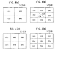
- Figs. 4(a)-4(d) show examples of division of the imaging surface S2 of the image sensor 53
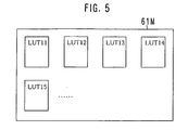
- Fig. 5 shows an example of contents of a memory 61M of the system controller 61
- Fig. 6 shows an example of a specific value of a parameter for each area ER
- Fig. 7 shows another example of a specific value of a parameter for each area ER
- Fig. 8 shows a graph of values of the parameters corresponding to Fig. 6
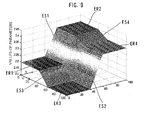
- Fig. 9 shows a graph of values of the parameters corresponding to Fig. 7.
- the imaging surface S2 is divided into four areas ER1-ER4 having the same size.
- the imaging surface S2 is divided into four areas ER1-ER4 having the same size, and interpolation areas ES1-ES6 are provided so that values of the parameters are continuous at boundaries of the sectioned areas ER1-ER4 as being described later.
- the areas ER1-ER4 become smaller because of the generated interpolation areas ES1-ES6.
- the imaging surface S2 is divided into six areas ER1-ER6 having the same size.
- the imaging surface S2 is divided into nine areas ER1-ER9 having the same size.
- the interpolation areas ES may be added as described above.
- the imaging surface S2 is divided into plural areas ER having the same size in these examples, the areas ER may have different sizes. For example, it is possible to divide so that peripheral areas have a smaller size relatively. In addition, it is possible to divide into two areas ER, three areas ER, or ten or more areas ER.
- the imaging surface S2 of the image sensor 53 is divided into plural areas ER in order to compute the three-dimensional coordinates corresponding to each pixel in accordance with the measured data of each pixel by using a parameter to be applied to each area ER to which each pixel belongs. Therefore, the parameter to be applied to each area ER is stored in the memory 61M of the system controller 61.
- the memory 61M a nonvolatile memory or a memory with battery backup can be used.
- the function of dividing the imaging surface S2 into plural areas ER or interpolation areas ES is included in the system controller 61.
- the system controller 61 sends the area division information to the output process circuit 62 in cooperation with control of the driver 55 for driving the image sensor 53, for example.
- the area division information is information that indicates the areas ER1-ER4 and the interpolation areas ES1-ES6 as shown in Figs. 4(a)-4(d), 6 and 7 for the measured data Ds of each pixel, for example.
- the memory 61M stores a lot of look-up tables LUT11, LUT12, LUT13....
- These look-up tables LUT store values or computing equations of parameters that are used for computing the three-dimensional shape (including shooting condition data and other data).
- the look-up table LUT stores values of various parameters including a camera parameter and a light projecting optical system parameter in the form of table.
- each of the look-up tables LUT stores a value of a parameter to be applied to each sectioned area ER on the imaging surface S2 and a computing equation or a value of a parameter to be applied to each interpolation area ES.
- the host computer 3 computes the three-dimensional coordinates, it uses an optimal parameter for each area ER and applies a camera sight line equation and a detection light plane equation.
- Fig. 6 shows an example of values of parameters to be applied to the sectioned areas ER1-ER4 concerning a certain parameter PM1 when the imaging surface S2 is divided into the four areas ER1-ER4 as shown in Fig. 4(a).
- values "2.2", “2.4", “2.1” and "2.35" are used as values of a certain parameter PM1 for the areas ER1-ER4, respectively.
- the memory 61M stores relationships between the areas ER1-ER4 and values of parameters as the look-up tables LUT for types of parameters.
- Appropriate values of parameters in each area ER are determined by actual measurement for each three-dimensional camera 2, so that optimal values are determined for each area ER in an experimental manner.
- the actual measurement itself for determining values of parameters can be performed by a conventionally known method.
- One of characteristics of this embodiment is that the imaging surface S2 is divided into plural areas ER, and values of optimal parameters are determined by real measurement for each area ER. Namely, in the conventional method, the imaging surface S2 is not divided into areas ER, and only one value is used for one parameter regardless of an area of the imaging surface S2.
- Fig. 7 shows an example of values or of computing equations of parameters to be applied to the areas ER1-ER4 and the interpolation areas ES1-ES6 provided to the imaging surface S2 as shown in Fig. 4(b) for the same parameter PM1 as in Fig. 6.
- u1 and u2 denote pixel positions at both ends in the horizontal direction in the interpolation areas ES1 and ES2
- v1 and v2 denote pixel positions at both ends in the vertical direction in the interpolation areas ES3 and ES4.
- the same values as the case shown in Fig. 6 are used for the areas ER1-ER4, while f1(u), f2(u), f3(v), f4(v), f5(u,v) and f6(u,v) are used for the interpolation areas ES1-ES6.
- f1(u) and f3(v) can be expressed as follows.
- f ⁇ 1 u 2.2 + a ⁇ 1 ⁇ u - u ⁇ 1
- f ⁇ 3 v 2.2 + a ⁇ 3 ⁇ v - v ⁇ 1
- u or v denotes a pixel position in the horizontal direction or in the vertical direction on the imaging surface S2, while a1 and a3 are coefficients that are determined in accordance with values of parameters in the area ER that is adjacent to the interpolation area ES.
- Equations f5(u,v) and f6(u,v) are expressed by the plane equation that is defined by three points.
- the memory 61M stores relationships between the areas ER1-ER4 as well as the interpolation areas ES1-ES6 and values or computing equations of the parameters as the look-up tables LUT for each type of the parameters. Note that it is possible to store a value of the pixel individually for the interpolation areas ES1-ES6 instead of the computing equation of the parameter.
- the imaging surface S2 is divided into areas ER1-ER4, and interpolation areas ES1-ES6 are provided so that values of parameters become continuous.
- the three-dimensional coordinates of the sampling points can be determined more precisely.
- Fig. 8 shows an example that is the same as the values of parameters shown in Fig. 6, in the form of a height distribution of parameter values for the area ER on the imaging surface S2 indicated by the XY coordinates.
- each of the X axis and the Y axis has a scale of 0-100. This can be considered there is an imaging surface S2 of 100 x 100 pixels, for example. Alternatively, it can be considered that pixel positions in the X direction and in the Y direction on the imaging surface S2 of Nx x Ny pixels are expressed on a percentage basis.
- the imaging surface S2 of the image sensor 53 has 640 x 480 pixels in this embodiment.
- Fig. 9 shows an example that is the same as the values and the computing equations of parameters shown in Fig. 7, in the form of a height distribution of parameter values for the area ER and the interpolation area ES on the imaging surface S2 indicated by the XY coordinates.
- the three-dimensional coordinates there are following parameters that are necessary for computing the three-dimensional coordinates. Namely, there are an image distance b, distortion aberration parameters d1 and d2, a center pixel position u0 in the horizontal direction on the imaging surface, and a center pixel position v0 in the vertical direction as the camera parameter.
- the measured data corresponding to each pixel are generated and are stored in the memory 63, an operator issues instruction to an output of data. Then, the measured data are delivered on line in a predetermined form by a SCSI controller 66 or an NTSC conversion circuit 65 or are stored in the recording medium 4. On this occasion, parameters stored in the memory 61M are also delivered together with the measured data.
- the on-line output of the measured data is performed via the analog output terminal 31 or the digital output terminal 33.
- the imaging information of the color image sensor 54 is transmitted to a color processing circuit 67 in synchronization with a clock from a driver 56.
- the imaging information after the color process is delivered on line via an NTSC conversion circuit 70 and the analog output terminal 32 or is digitized by a digital image generating portion 68 so as to be stored in a color image memory 69.
- the color image data are transmitted from the color image memory 69 to the SCSI controller 66, are delivered from the digital output terminal 33 on line, or are stored in connection with the measured data in the recording medium 4.
- the color image is an image having an angle of view that is the same as a distance image obtained by the image sensor 53 and is used as reference information when the host computer 3 performs an application process.
- the process using the color information there is a process for generating a three-dimensional shape model by combining plural sets of measured data having different camera eye points or a process for thinning unnecessary vertexes from a three-dimensional shape model.
- the system controller 61 gives instruction to a character generator 71 for displaying appropriate characters and symbols on the screen of the LCD 21.
- the memory 63 can deliver its memorized information to the system controller 61.
- Figs. 10(a) and 10(b) show a principle for calculating a three-dimensional position by the measuring system 1.
- the same reference symbols denote the same elements as in Figs. 18(a)-18(d) and 19(a)-19(c) for easy understanding.
- the slit light U having relatively large width is projected onto the object Q so that it covers plural pixels on the imaging surface S2 of the image sensor 53. More specifically, the width of the slit light U is set to a value corresponding to five pixels.
- the slit light U is deflected downward so as to move by one pixel pitch pv on the imaging surface S2 every sampling period, thereby the object Q is scanned.
- the image sensor 53 produces photoelectric conversion information of one frame every sampling period.
- a position (coordinates) of the object Q is calculated in accordance with a relationship between the direction of projecting the slit light and an incident direction of the slit light on the target pixel g at the determined timing.
- the three-dimensional camera 2 delivers the received light data of the image sensor 53 of five times per pixel g as measured data to the host computer 3, and the host computer 3 calculates coordinates of the object Q in accordance with the measured data.
- the output process circuit 62 performs the generation of the measured data corresponding to each pixel g in the three-dimensional camera 2.
- the number of sampling points in the measurement is regarded as 244 x 256. Namely, the substantial number of frames N is 244, while the number of pixels in the slit lengthwise direction on the imaging surface S2 is 256.
- the user determines a position and an orientation of the camera by viewing a color monitor image displayed on the LCD 21 and sets the angle of view. If necessary, the user performs a zooming operation.
- the three-dimensional camera 2 does not perform aperture adjustment for the color image sensor 54, and an electronic shutter function is used for exposure control so as to display a color monitor image.
- the aperture is set to an opened state so that light quantity to be received by the image sensor 53 becomes as much as possible.
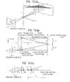
- Fig. 11 shows a flow of data in the three-dimensional camera 2
- Fig. 12 shows a flow of data in the host computer 3
- Fig. 13 shows a position relationship between points of the optical system and the object Q.
- a variator portion of the zoom unit 51 moves, and a focusing operation is performed by movement of a focusing portion.
- a distance d0 to the object is roughly measured.
- a travel of a variator lens on the light projecting side is computed, and the movement of the variator lens is controlled in accordance with a result of the computation.
- the lens control on the light projecting side is for the image sensor 53 to receive the slit light U of the width corresponding to five pixels regardless of a shooting distance and the angle of view.
- the system controller 61 reads an encoder output of the focus driving system 59 (turn out quantity Ed) and an encoder output of the zoom driving system 60 (a zoom pitch value fp) via the lens controller 58.
- the distortion aberration table LUT13, the principal point position table LUT14 and the image distance table LUT15 are referred so that the shooting condition data that are parameters corresponding to the turn out quantity Ed and the zoom pitch value fp are delivered to the host computer 3.
- the shooting condition data are distortion aberration parameters (lens distortion correction coefficients d1 and d2), a front principal point position FH and the image distance b.
- the front principal point position FH is expressed by a distance between a front end point F and a front principal point H of the zoom unit 51 (see Fig. 19(c)). As the front end point F is fixed, the front principal point H can be specified by the front principal point position FH.
- the area division information is read out of the area division information table LUT11, and device information is read out of the device information table LUT12. Each of them is delivered to the host computer 3.
- the system controller 61 performs preliminary measurement by projecting the slit light U in a specific direction for measuring a measurement environment, determines the distance d to the object in accordance with shooting information obtained by the preliminary measurement, resets the turn out quantity Ed in accordance with the distance d to the object so as to drive the lens, and sets operation for real measurement.
- Set items include a power of the semiconductor laser 41 (a laser beam intensity), a condition for deflecting the slit light U (a projection start angle, a projection end angle, and a deflection angular velocity).
- the distance d to the object is calculated, it is necessary to consider an offset doff in the Z direction between the front principal point H of the light receiving system that is a reference point for measuring a distance and the starting point A of the emitted light.
- the deflection condition is calculated, it is necessary to perform an over scan by a predetermined quantity (corresponding to 8 pixels, for example) so as to secure a measurable distance range d' at the end portion in the scanning direction in the same manner as the middle portion.
- the projection start angle th1, the projection end angle th2 and the deflection angular velocity ⁇ are expressed by the following equations.
- pv pixel pitch
- np effective number of pixels in the Y direction on the imaging surface
- S2 L base line length
- the real measurement is performed under the condition obtained by the calculation described above.
- the object Q is scanned, and the measured data (slit image data) Ds corresponding to five frames per pixel obtained by the output process circuit 62 are sent to the host computer 3.
- the deflection condition (the deflection control data D43) and device information D10 indicating a specification of the image sensor 53 are sent to the host computer 3.
- Table 1 shows main data that are sent from the three-dimensional camera 2 to the host computer 3.
- the reference position for calculating a distance to the object is set to the close position of the object (the three-dimensional camera 2 side) and the measurable distance range d' is set so as to include the close position as being described later, the measurable distance range at the front side (the three-dimensional camera 2 side) usually becomes waste. Therefore, it is desirable to set the shift quantity pitchoff to be 25% at the front side and 75% at the rear side so that the measurable distance range d' is shifted to the rear side.
- the effective light reception area Ae has a width corresponding to 32 pixels, i.e., if the CCD area sensor has a width corresponding to 32 lines like this embodiment, the measurable distance range of the above-mentioned ratio is set when the shift quantity pitchoff is "8".
- the host computer 3 computes the three-dimensional coordinates of each sampling point in accordance with the measured data Ds received from the three-dimensional camera 2.
- Fig. 12 it is determined first which area ER the measured data Ds belong to in accordance with the area division information that is attached to the received measured data Ds.
- a parameter to be applied is extracted from the look-up tables LUT in accordance with the information that indicates the determined area ER (area information).
- a slit barycenter calculation, a correction calculation of the distortion aberration, a calculation of the camera sight line equation, a calculation of a slit plane equation and a three-dimensional position calculation are performed by using the extracted parameter, so that the three-dimensional positions (coordinates X, Y and Z) are determined for 244 x 256 sampling points.
- the sampling point is an intersection of a camera sight line (a straight line linking the sampling point and the front principal point H) and a slit plane (an optical axis plane of the slit light U that projects the sampling point).
- Influence of ambient light can be reduced by determining a weighted average after subtracting the minimum data minDg(i) among five received light data.
- the camera sight line equation is defined by the equations (5) and (6) below.
- FH front principal point position pu: pixel pitch in the horizontal direction on the imaging surface
- pv pixel pitch in the vertical direction on the imaging surface
- u pixel position in the horizontal direction on the imaging surface
- u0 center pixel position in the horizontal direction on the imaging surface
- v pixel position in the vertical direction on the imaging surface v0: center pixel position in the vertical direction on the imaging surface
- slit plane equation is defined by the equation (7) below.
- X - a , Y - L , Z - s ⁇ R ⁇ 0 ⁇ 1 ⁇ 0 t 0 a: error along the X axis
- L base line length
- the camera sight line equation and the slit plane equation (the detection light plane equation) defined by the equations (5), (6) and (7) are solved so that the three-dimensional coordinates (X, Y, Z) corresponding to pixels indicated by coordinates (u, v) on the imaging surface S2 are calculated.
- the calculation is performed by using a parameter corresponding to the area ER to which each pixel belongs when applying the equations (5), (6) and (7).
- a geometrical aberration depends on the angle of view.
- the distortion is generated substantially in a symmetric manner around the center pixel. Therefore, the distortion quantity is defined by a function of a distance from the center pixel.
- an approximation is made by a cubic function of the distance.
- a quadratic correction coefficient is represented by d1
- a cubic correction coefficient is represented by d2.
- the parameter extracted from the memory 61M of the three-dimensional camera 2 is transmitted to the host computer 3 with reference to Figs. 11 and 12, but this structure should not be considered to be a limitation. Namely, it is possible, for example, to transmit all the look-up tables LUT stored in the memory 61M when transmitting the measured data Ds from the three-dimensional camera 2, so that the host computer 3 can store the look-up tables LUT and extract a necessary parameter. In addition, it is possible to install the look-up table LUT that is the same as that of the three-dimensional camera 2 in the host computer 3 from the beginning. As means for storing the parameter PM for that purpose, an appropriate memory embedded in the CPU 3a or an external one can be used.
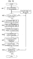
- Fig. 14 is a flowchart showing a flow of a process for obtaining the parameter
- Fig. 15 is a flowchart showing a flow of a process when an interpolation area ES is provided
- Fig. 16 is a flowchart showing a flow of a process for computing three-dimensional coordinates by the measuring system 1.
- data for calibration are measured first (#21).
- the data for calibration are obtained by measuring an optical error, an electrical error and a mechanical error for each three-dimensional camera 2 as described above by various methods known conventionally. For example, an image of a known pattern arranged at a predetermined distance position is taken by the three-dimensional camera 2, and many data are obtained about which position the pattern is imaged on the imaging surface S2.
- slit light U is projected onto a wall that is arranged at a predetermined distance position, and a slit image data are obtained.
- the imaging surface S2 of the image sensor 53 is divided into plural areas ER (#22). Noting the sectioned one area ER (#23), a calibrated parameter is determined for the area ER (#24) and is stored in the memory temporarily (#25). This parameter is a value specified for each area ER as described above or a specific computing equation or the like. The corrected parameter has been determined for all areas ER (Yes in #26), the obtained parameter for each area ER and the area division information are produced (#27). The produced parameter and others are stored in the memory 61M of the three-dimensional camera 2.
- Step #37 the boundary portion of the area ER is divided again so that the interpolation area ES is provided. Then, a corrected parameter is determined for the interpolation area ES (#38), and the entire area division information and the parameter are updated by the determined parameter for the interpolation area ES (#39). The parameter and the area division information for each area ER and each interpolation area ES are produced (#40).
- one pixel of the image sensor 53 is noted (#51). If the image data of the pixel are effective (Yes in #52), the area ER to which the pixel belongs is determined (#53). The value of the parameter of the determined area ER is read out of the memory 61M or the like (#54). The read parameter is used for calculating the camera sight line equation and the slit plane equation (#55 and #56), and the three-dimensional coordinates are determined (#57). The obtained three-dimensional coordinates are stored in the memory (#58). When the calculation of the three-dimensional coordinates is performed for all pixels of the image sensor 53, the process is finished (#59).
- the measuring system 1 of this embodiment divides the imaging surface S2 of the image sensor 53 into plural areas ER, or further divides the same into interpolation areas ES, determines values or equations of a parameter that is suitable for each area, and uses a value or an equation of an optimal parameter for each area when calculating the three-dimensional coordinates. Therefore, the three-dimensional coordinates can be calculated precisely.
- the conventional system produces a curved slit image FS1 shown by the solid line for a flat object Q and processes it as a linear slit image FSj. Therefore, the difference between the two slit images FS1 and FSj becomes an error that causes decrease of accuracy of the three-dimensional coordinates.
- the measuring system 1 of this embodiment uses the corrected parameter for each area as shown in Fig. 17(b), so that the process is performed for the flat object Q regarding a slit image FS2 that is similar to the real slit image FS1 is obtained.
- the slit image FS2 is regarded as plural continuous lines each of which is a result of approximation for each area.
- the process of dividing the imaging surface S2 into plural areas and obtaining a parameter that is suitable for each area, the process for calculating three-dimensional coordinates using the parameter for each area or other process can be performed by software. Therefore, using existing hardware and adding software for performing the processes described above can realize the measuring system 1 of this embodiment. Thus, the structure is simple and advantageous for cost.
- areas that are sectioned in the same manner are used for the process of calibrating and obtaining a parameter for each area and for the process of calculating three-dimensional coordinates by using the parameter in the embodiment described above, the areas can be different from each other. Namely, areas that are used for calibration may be larger than areas that are used for calculating three-dimensional coordinates so that the areas that are used for calibration are overlapped with each other, for example.
- a parameter for the interpolation area ES by various methods. For example, concerning a certain interpolation area ES, it is possible to determine an equation or a value of a parameter of the same type for a neighboring area ER by interpolation using a straight line or a B-spline curve concerning a pixel in the vertical direction or a pixel in the horizontal direction.
- the measuring system 1 corresponds to the three-dimensional shape input device of the present invention.
- a structure is possible in which the three-dimensional camera 2 performs all the processes instead of the host computer 3.
- the three-dimensional camera 2 corresponds to the three-dimensional shape input device of the present invention.
- the three-dimensional camera 2 and the host computer 3 coordinate the processes in a manner different from the embodiment described above.
- the present invention can be applied to various structures of three-dimensional shape input devices utilizing the light projection method, including a structure in which the light projecting portion projects fixed slit light as detection light, and a structure in which a density pattern or a stripe pattern is projected as the detection light.
- a structure of the memory 61M, contents of the look-up table LUT, as well as the structure, the configuration, the shape, the dimensions, the functions, the numbers, the positions, the process contents, the process order or others of the entire or a part of the three-dimensional camera 2, the host computer 3 or the measuring system 1 can be modified variously in accordance with the spirit of the present invention.
- the present invention can be used for a three-dimensional shape input device that measures and enters a three-dimensional shape of an object in a noncontact manner by using the light projection method.
Landscapes
- Engineering & Computer Science (AREA)
- Computer Vision & Pattern Recognition (AREA)
- Physics & Mathematics (AREA)
- General Physics & Mathematics (AREA)
- Length Measuring Devices By Optical Means (AREA)
- Image Processing (AREA)
- Image Analysis (AREA)
Claims (9)
- Dispositif de détermination de la forme d'un objet tridimensionnel (1) pour entrer et mesurer la forme tridimensionnelle d'un objet (Q) par un procédé de projection de lumière, le dispositif comprenant :une portion de projection de lumière (40) pour projeter la lumière de détection sur un objet (Q),un capteur d'image (53) pour recevoir la lumière réfléchie par l'objet (Q),une portion de mémorisation (61M) pour mémoriser un paramètre qui est utilisé pour calculer la forme tridimensionnelle, etune portion de calcul (3a) pour calculer et déterminer la forme tridimensionnelle de l'objet (Q) en utilisant les données d'image fournies par le capteur d'image (53) et le paramètre,caractérisé en ce quele dispositif (1) comprend une portion de division pour diviser la surface d'image (S2) du capteur d'image (53) en une pluralité de zones (ER),la portion de mémorisation (61M) mémorise plusieurs paramètres à appliquer sur la pluralité de zones, respectivement, etla portion de calcul (3a) calcule et déterminer la forme tridimensionnelle pour chacune des zones (ER) en utilisant pour chacune des zones (ER) le paramètre respectif à appliquer.
- Dispositif selon la revendication 1, caractérisé en ce que la portion de calcul (3a) effectue le calcul en utilisant une équation de ligne de visée par caméra et une équation de plan de lumière de détection.
- Dispositif selon la revendication 2, caractérisé en ce que la portion de calcul (3a) effectue le calcul pour chacune des zones (ER) en utilisant pour chacune des zones (ER) le paramètre respectif à appliquer en tant que paramètre de caméra qui est utilisé pour l'équation de ligne de visée par caméra.
- Dispositif selon la revendication 2, caractérisé en ce que la portion de calcul (3a) effectue le calcul pour chacune des zones (ER) en utilisant pour chacune des zones (ER) le paramètre respectif à appliquer en tant que paramètre de système optique de projection de lumière qui est utilisé pour l'équation de plan de lumière de détection.
- Dispositif selon la revendication 4, caractérisé en ce que la portion de projection de lumière (40) projette la lumière de fente en tant que lumière de détection.
- Dispositif selon la revendication 4, caractérisé en ce que la portion de projection de lumière (40) scanne l'objet (Q) en faisant dévier la lumière de fente projetée, et la portion de calcul (3a) effectue le calcul en utilisant pour chacune des zones (RE) le paramètre respectif à appliquer qui comprend un paramètre de vitesse angulaire d'un miroir déflecteur pour faire dévier la lumière de fente.
- Dispositif selon la revendication 4, caractérisé en ce que la portion de projection de lumière (40) projette une lumière de configuration en bande en tant que lumière de détection.
- Dispositif selon l'une quelconque des revendications 1 à 7, caractérisé en ce que le paramètre à appliquer pour chacune des zones (ER) est interpolé de telle sorte qu'une valeur du paramètre devient continue au niveau d'une limite des zones (ER).
- Dispositif selon l'une quelconque des revendications 1 à 8, caractérisé en ce que les données d'image comprennent des informations de division de zone pour distinguer une zone (ER) à laquelle fait partie chacune des données d'image.
Applications Claiming Priority (2)
| Application Number | Priority Date | Filing Date | Title |
|---|---|---|---|
| JP2004138927A JP4111166B2 (ja) | 2004-05-07 | 2004-05-07 | 3次元形状入力装置 |
| JP2004138927 | 2004-05-07 |
Publications (2)
| Publication Number | Publication Date |
|---|---|
| EP1596158A1 EP1596158A1 (fr) | 2005-11-16 |
| EP1596158B1 true EP1596158B1 (fr) | 2007-12-05 |
Family
ID=34935880
Family Applications (1)
| Application Number | Title | Priority Date | Filing Date |
|---|---|---|---|
| EP05009321A Not-in-force EP1596158B1 (fr) | 2004-05-07 | 2005-04-28 | Dispositif pour déterminer la forme d'un objet en trois dimensions |
Country Status (4)
| Country | Link |
|---|---|
| US (1) | US7454054B2 (fr) |
| EP (1) | EP1596158B1 (fr) |
| JP (1) | JP4111166B2 (fr) |
| DE (1) | DE602005003610T2 (fr) |
Cited By (1)
| Publication number | Priority date | Publication date | Assignee | Title |
|---|---|---|---|---|
| US10952827B2 (en) | 2014-08-15 | 2021-03-23 | Align Technology, Inc. | Calibration of an intraoral scanner |
Families Citing this family (48)
| Publication number | Priority date | Publication date | Assignee | Title |
|---|---|---|---|---|
| ATE383817T1 (de) | 2004-06-17 | 2008-02-15 | Cadent Ltd | Verfahren zum bereitstellen von daten im zusammenhang mit der mundhöhle |
| US7742624B2 (en) * | 2006-04-25 | 2010-06-22 | Motorola, Inc. | Perspective improvement for image and video applications |
| JP4380663B2 (ja) | 2006-06-08 | 2009-12-09 | コニカミノルタセンシング株式会社 | 三次元形状測定方法、装置、及びフォーカス調整方法 |
| JP4315169B2 (ja) | 2006-06-15 | 2009-08-19 | コニカミノルタセンシング株式会社 | 三次元形状測定システム |
| JP2008002995A (ja) * | 2006-06-23 | 2008-01-10 | Konica Minolta Sensing Inc | 三次元形状測定装置 |
| JP4437485B2 (ja) * | 2006-09-29 | 2010-03-24 | コニカミノルタセンシング株式会社 | 測定システム及びその動作プログラム |
| JP4843544B2 (ja) * | 2007-03-29 | 2011-12-21 | 日本放送協会 | 3次元画像補正方法及びその装置 |
| JP5136108B2 (ja) * | 2008-02-18 | 2013-02-06 | トヨタ自動車株式会社 | 三次元形状計測方法および三次元形状計測装置 |
| US8160992B2 (en) | 2008-05-15 | 2012-04-17 | Xerox Corporation | System and method for selecting a package structural design |
| US8915831B2 (en) | 2008-05-15 | 2014-12-23 | Xerox Corporation | System and method for automating package assembly |
| US7788883B2 (en) * | 2008-06-19 | 2010-09-07 | Xerox Corporation | Custom packaging solution for arbitrary objects |
| US9132599B2 (en) | 2008-09-05 | 2015-09-15 | Xerox Corporation | System and method for image registration for packaging |
| US8174720B2 (en) * | 2008-11-06 | 2012-05-08 | Xerox Corporation | Packaging digital front end |
| US9493024B2 (en) * | 2008-12-16 | 2016-11-15 | Xerox Corporation | System and method to derive structure from image |
| US8170706B2 (en) | 2009-02-27 | 2012-05-01 | Xerox Corporation | Package generation system |
| JP5310130B2 (ja) * | 2009-03-11 | 2013-10-09 | オムロン株式会社 | 3次元視覚センサによる認識結果の表示方法および3次元視覚センサ |
| JP5245938B2 (ja) * | 2009-03-12 | 2013-07-24 | オムロン株式会社 | 3次元認識結果の表示方法および3次元視覚センサ |
| JP2010210585A (ja) * | 2009-03-12 | 2010-09-24 | Omron Corp | 3次元視覚センサにおけるモデル表示方法および3次元視覚センサ |
| JP5316118B2 (ja) * | 2009-03-12 | 2013-10-16 | オムロン株式会社 | 3次元視覚センサ |
| JP5714232B2 (ja) * | 2009-03-12 | 2015-05-07 | オムロン株式会社 | キャリブレーション装置および3次元計測のためのパラメータの精度の確認支援方法 |
| JP5282614B2 (ja) * | 2009-03-13 | 2013-09-04 | オムロン株式会社 | 視覚認識処理用のモデルデータの登録方法および視覚センサ |
| US8432395B2 (en) * | 2009-06-16 | 2013-04-30 | Apple Inc. | Method and apparatus for surface contour mapping |
| US8775130B2 (en) * | 2009-08-27 | 2014-07-08 | Xerox Corporation | System for automatically generating package designs and concepts |
| EP2496910A4 (fr) * | 2009-11-04 | 2016-11-16 | Technologies Numetrix Inc | Dispositif et procédé d'obtention de données de surface d'objet tridimensionnelles |
| US9082207B2 (en) * | 2009-11-18 | 2015-07-14 | Xerox Corporation | System and method for automatic layout of printed material on a three-dimensional structure |
| US20110119570A1 (en) * | 2009-11-18 | 2011-05-19 | Xerox Corporation | Automated variable dimension digital document advisor |
| US8643874B2 (en) | 2009-12-18 | 2014-02-04 | Xerox Corporation | Method and system for generating a workflow to produce a dimensional document |
| JP5170154B2 (ja) | 2010-04-26 | 2013-03-27 | オムロン株式会社 | 形状計測装置およびキャリブレーション方法 |
| JP5587137B2 (ja) * | 2010-10-29 | 2014-09-10 | キヤノン株式会社 | 測定装置及び測定方法 |
| KR20140022858A (ko) * | 2011-04-01 | 2014-02-25 | 가부시키가이샤 니콘 | 형상 측정 장치, 형상 측정 방법, 및 구조물의 제조 방법 |
| US8757479B2 (en) | 2012-07-31 | 2014-06-24 | Xerox Corporation | Method and system for creating personalized packaging |
| US8994734B2 (en) | 2012-07-31 | 2015-03-31 | Xerox Corporation | Package definition system |
| US9314986B2 (en) | 2012-10-31 | 2016-04-19 | Xerox Corporation | Method and system for applying an adaptive perforation cut to a substrate |
| JP6029938B2 (ja) * | 2012-11-06 | 2016-11-24 | ローランドディー.ジー.株式会社 | キャリブレーション方法および三次元加工装置 |
| US9245209B2 (en) | 2012-11-21 | 2016-01-26 | Xerox Corporation | Dynamic bleed area definition for printing of multi-dimensional substrates |
| JP6021764B2 (ja) | 2013-08-30 | 2016-11-09 | 株式会社東芝 | 検査装置および検査方法 |
| US9760659B2 (en) | 2014-01-30 | 2017-09-12 | Xerox Corporation | Package definition system with non-symmetric functional elements as a function of package edge property |
| US9780873B2 (en) * | 2014-03-25 | 2017-10-03 | Osram Sylvania Inc. | Light-based communication transmission protocol |
| US9892212B2 (en) | 2014-05-19 | 2018-02-13 | Xerox Corporation | Creation of variable cut files for package design |
| US9916401B2 (en) | 2015-05-18 | 2018-03-13 | Xerox Corporation | Creation of cut files for personalized package design using multiple substrates |
| US9916402B2 (en) | 2015-05-18 | 2018-03-13 | Xerox Corporation | Creation of cut files to fit a large package flat on one or more substrates |
| CN106791294A (zh) * | 2016-11-25 | 2017-05-31 | 益海芯电子技术江苏有限公司 | 运动目标跟踪方法 |
| ES2967431T3 (es) | 2017-07-28 | 2024-04-30 | Stratasys Ltd | Formulaciones utilizables en la fabricación aditiva de un objeto tridimensional hecho de un material blando |
| ES2970615T3 (es) | 2017-07-28 | 2024-05-29 | Stratasys Ltd | Método y sistema para elaborar un objeto que presenta propiedades de un tejido duro |
| JP7329498B2 (ja) * | 2017-07-28 | 2023-08-18 | ストラタシス リミテッド | 血管の特性を具備する物体を製作するための方法及びシステム |
| KR101955847B1 (ko) * | 2018-01-23 | 2019-03-11 | 한국표준과학연구원 | 위상천이 편향측정법에서 비선형 응답특성을 보상하기 위한 시스템 및 방법 |
| JP7219058B2 (ja) * | 2018-11-09 | 2023-02-07 | 株式会社キーエンス | 変位測定装置 |
| US20240020935A1 (en) * | 2022-07-15 | 2024-01-18 | The Boeing Company | Modeling system for 3d virtual model |
Family Cites Families (11)
| Publication number | Priority date | Publication date | Assignee | Title |
|---|---|---|---|---|
| US6407817B1 (en) * | 1993-12-20 | 2002-06-18 | Minolta Co., Ltd. | Measuring system with improved method of reading image data of an object |
| JP3282332B2 (ja) * | 1993-12-20 | 2002-05-13 | ミノルタ株式会社 | 画像入力システム |
| JP3893169B2 (ja) | 1996-06-18 | 2007-03-14 | コニカミノルタホールディングス株式会社 | 3次元計測装置 |
| US6141105A (en) * | 1995-11-17 | 2000-10-31 | Minolta Co., Ltd. | Three-dimensional measuring device and three-dimensional measuring method |
| JP3493403B2 (ja) | 1996-06-18 | 2004-02-03 | ミノルタ株式会社 | 3次元計測装置 |
| US6049385A (en) * | 1996-06-05 | 2000-04-11 | Minolta Co., Ltd. | Three dimensional measurement system and pickup apparatus |
| JP2913021B2 (ja) | 1996-09-24 | 1999-06-28 | 和歌山大学長 | 形状計測方法及び装置 |
| JPH10326345A (ja) | 1997-05-23 | 1998-12-08 | N T T Data:Kk | 3次元形状推定方法及び3次元形状推定システム |
| JP3837882B2 (ja) | 1997-11-18 | 2006-10-25 | カシオ計算機株式会社 | 撮影画像管理装置およびそのプログラム記録媒体 |
| JP2002058046A (ja) | 2000-08-11 | 2002-02-22 | Minolta Co Ltd | 撮像システムおよび3次元カメラ |
| US6603462B2 (en) * | 2001-03-21 | 2003-08-05 | Multidigit, Inc. | System and method for selecting functions based on a finger feature such as a fingerprint |
-
2004
- 2004-05-07 JP JP2004138927A patent/JP4111166B2/ja not_active Expired - Fee Related
-
2005
- 2005-04-28 EP EP05009321A patent/EP1596158B1/fr not_active Not-in-force
- 2005-04-28 DE DE602005003610T patent/DE602005003610T2/de active Active
- 2005-05-03 US US11/121,333 patent/US7454054B2/en not_active Expired - Fee Related
Cited By (1)
| Publication number | Priority date | Publication date | Assignee | Title |
|---|---|---|---|---|
| US10952827B2 (en) | 2014-08-15 | 2021-03-23 | Align Technology, Inc. | Calibration of an intraoral scanner |
Also Published As
| Publication number | Publication date |
|---|---|
| DE602005003610D1 (de) | 2008-01-17 |
| US7454054B2 (en) | 2008-11-18 |
| JP4111166B2 (ja) | 2008-07-02 |
| DE602005003610T2 (de) | 2008-11-27 |
| JP2005321278A (ja) | 2005-11-17 |
| EP1596158A1 (fr) | 2005-11-16 |
| US20050249400A1 (en) | 2005-11-10 |
Similar Documents
| Publication | Publication Date | Title |
|---|---|---|
| EP1596158B1 (fr) | Dispositif pour déterminer la forme d'un objet en trois dimensions | |
| US6529280B1 (en) | Three-dimensional measuring device and three-dimensional measuring method | |
| JP3873401B2 (ja) | 3次元計測システム | |
| JP4111592B2 (ja) | 3次元入力装置 | |
| US7812969B2 (en) | Three-dimensional shape measuring apparatus | |
| TWI740237B (zh) | 光學相位輪廓測定系統 | |
| KR20060031685A (ko) | 이미지 프로젝터, 경사각 검출방법, 및 투사 이미지정정방법 | |
| KR100481399B1 (ko) | 촬상 시스템, 상기 시스템에서 화상 데이터를 제어하도록사용되는 프로그램, 상기 시스템에서 촬상 화상의 왜곡을보정하기 위한 방법 및 상기 방법의 순서를 기억시키는기록 매체 | |
| US6424422B1 (en) | Three-dimensional input device | |
| WO2009120073A2 (fr) | Explorateur tridimensionnel auto-référencé à lumière structurée et à étalonnage dynamique | |
| CN113160416B (zh) | 一种用于煤流检测的散斑成像装置及方法 | |
| JP3493403B2 (ja) | 3次元計測装置 | |
| JP4186347B2 (ja) | 3次元入力方法及び装置 | |
| JPH102712A (ja) | 3次元計測装置 | |
| US5721611A (en) | Photogrammetric camera, in particular for photogrammetric measurements of technical objects | |
| JP2002022424A (ja) | 3次元測定装置 | |
| JP2000292121A (ja) | 3次元計測方法及び3次元入力装置 | |
| JP2961140B2 (ja) | 画像処理方法 | |
| JPH09145320A (ja) | 3次元入力カメラ | |
| JP3861475B2 (ja) | 3次元入力装置 | |
| JP3733625B2 (ja) | 3次元計測のための撮像装置 | |
| JPH09145319A (ja) | 3次元計測方法及び装置 | |
| JP4032556B2 (ja) | 3次元入力装置 | |
| JP2000002520A (ja) | 3次元入力装置 | |
| JP2002031511A (ja) | 3次元デジタイザ |
Legal Events
| Date | Code | Title | Description |
|---|---|---|---|
| PUAI | Public reference made under article 153(3) epc to a published international application that has entered the european phase |
Free format text: ORIGINAL CODE: 0009012 |
|
| AK | Designated contracting states |
Kind code of ref document: A1 Designated state(s): AT BE BG CH CY CZ DE DK EE ES FI FR GB GR HU IE IS IT LI LT LU MC NL PL PT RO SE SI SK TR |
|
| AX | Request for extension of the european patent |
Extension state: AL BA HR LV MK YU |
|
| 17P | Request for examination filed |
Effective date: 20060315 |
|
| AKX | Designation fees paid |
Designated state(s): DE FR GB |
|
| 17Q | First examination report despatched |
Effective date: 20060627 |
|
| 17Q | First examination report despatched |
Effective date: 20060627 |
|
| GRAP | Despatch of communication of intention to grant a patent |
Free format text: ORIGINAL CODE: EPIDOSNIGR1 |
|
| GRAC | Information related to communication of intention to grant a patent modified |
Free format text: ORIGINAL CODE: EPIDOSCIGR1 |
|
| GRAS | Grant fee paid |
Free format text: ORIGINAL CODE: EPIDOSNIGR3 |
|
| GRAA | (expected) grant |
Free format text: ORIGINAL CODE: 0009210 |
|
| AK | Designated contracting states |
Kind code of ref document: B1 Designated state(s): DE FR GB |
|
| REG | Reference to a national code |
Ref country code: GB Ref legal event code: FG4D |
|
| REF | Corresponds to: |
Ref document number: 602005003610 Country of ref document: DE Date of ref document: 20080117 Kind code of ref document: P |
|
| ET | Fr: translation filed | ||
| PLBE | No opposition filed within time limit |
Free format text: ORIGINAL CODE: 0009261 |
|
| STAA | Information on the status of an ep patent application or granted ep patent |
Free format text: STATUS: NO OPPOSITION FILED WITHIN TIME LIMIT |
|
| 26N | No opposition filed |
Effective date: 20080908 |
|
| PGFP | Annual fee paid to national office [announced via postgrant information from national office to epo] |
Ref country code: GB Payment date: 20120425 Year of fee payment: 8 Ref country code: FR Payment date: 20120504 Year of fee payment: 8 |
|
| GBPC | Gb: european patent ceased through non-payment of renewal fee |
Effective date: 20130428 |
|
| PG25 | Lapsed in a contracting state [announced via postgrant information from national office to epo] |
Ref country code: GB Free format text: LAPSE BECAUSE OF NON-PAYMENT OF DUE FEES Effective date: 20130428 |
|
| REG | Reference to a national code |
Ref country code: FR Ref legal event code: ST Effective date: 20131231 |
|
| PG25 | Lapsed in a contracting state [announced via postgrant information from national office to epo] |
Ref country code: FR Free format text: LAPSE BECAUSE OF NON-PAYMENT OF DUE FEES Effective date: 20130430 |
|
| PGFP | Annual fee paid to national office [announced via postgrant information from national office to epo] |
Ref country code: DE Payment date: 20150422 Year of fee payment: 11 |
|
| REG | Reference to a national code |
Ref country code: DE Ref legal event code: R119 Ref document number: 602005003610 Country of ref document: DE |
|
| PG25 | Lapsed in a contracting state [announced via postgrant information from national office to epo] |
Ref country code: DE Free format text: LAPSE BECAUSE OF NON-PAYMENT OF DUE FEES Effective date: 20161101 |