EP1596135A2 - Porte d'un appareil ménager - Google Patents
Porte d'un appareil ménager Download PDFInfo
- Publication number
- EP1596135A2 EP1596135A2 EP05103870A EP05103870A EP1596135A2 EP 1596135 A2 EP1596135 A2 EP 1596135A2 EP 05103870 A EP05103870 A EP 05103870A EP 05103870 A EP05103870 A EP 05103870A EP 1596135 A2 EP1596135 A2 EP 1596135A2
- Authority
- EP
- European Patent Office
- Prior art keywords
- appliance door
- unit
- domestic appliance
- fastening
- front part
- Prior art date
- Legal status (The legal status is an assumption and is not a legal conclusion. Google has not performed a legal analysis and makes no representation as to the accuracy of the status listed.)
- Withdrawn
Links
Images


Classifications
-
- F—MECHANICAL ENGINEERING; LIGHTING; HEATING; WEAPONS; BLASTING
- F24—HEATING; RANGES; VENTILATING
- F24C—DOMESTIC STOVES OR RANGES ; DETAILS OF DOMESTIC STOVES OR RANGES, OF GENERAL APPLICATION
- F24C15/00—Details
- F24C15/02—Doors specially adapted for stoves or ranges
-
- F—MECHANICAL ENGINEERING; LIGHTING; HEATING; WEAPONS; BLASTING
- F24—HEATING; RANGES; VENTILATING
- F24C—DOMESTIC STOVES OR RANGES ; DETAILS OF DOMESTIC STOVES OR RANGES, OF GENERAL APPLICATION
- F24C15/00—Details
- F24C15/02—Doors specially adapted for stoves or ranges
- F24C15/04—Doors specially adapted for stoves or ranges with transparent panels
- F24C15/045—Doors specially adapted for stoves or ranges with transparent panels being dismountable, e.g. giving access for cleaning
Definitions
- the invention is particularly based on a household appliance door according to the preamble of claim 1.
- the appliance door has a of an outer visor formed front part, which forms a front surface, and has an inner part formed by an inner panel, which forms an inner surface.
- the outer visor is glued to the last unit, and the inner visor is via fasteners of a fastening unit latched to the strip unit held the inguinal unit.
- the object of the invention is, in particular, a generic household appliance door to provide with improved mounting properties.
- the object is achieved according to the invention solved by the features of claim 1, while advantageous Refinements and developments of the invention the dependent claims and claims can be removed.
- the invention is particularly based on a household appliance door with a bar unit, a front part forming a front surface and an inner surface forming one Inner part.
- a fastening unit is arranged at the front part and / or on the inner part.
- the term "arranged" is intended in In this context, in particular non-positively, materially and / or positively releasably and advantageously permanently attached, molded, cast and / or introduced be understood.
- the fastening means at least partially from a recess in the front part and / or inner part or advantageously of a physical, be formed in particular additional object.
- special is meant in Expressed in this context, that the fastening means in particular not solely by the shape of the front part and / or the inner part, i.
- the advantageous Strip unit excluding a direct adhesive connection with the front part and / or to be coupled to the inner part with at least one of them, i. it can be avoided that the front part and / or the inner part of the last unit must be glued.
- simply an advantageous home appliance door system with at least one and preferably a plurality of household appliance doors according to the invention and at least one alternative component can be achieved, in which an assembly with low effort on different alternatives can be switched.
- the alternative component can thereby be formed by various components that appear appropriate to the person skilled in the art be such as a handle, a bezel, etc., but especially advantageous of a front part and / or an inner part, by means of which simply in particular significant visual changes and function changes can be realized.
- the lens can advantageously be integrated as a carrier component and further carrier components can at least be dimensioned weaker and cheaper and / or even eliminated.
- the two viewing panes of an outer and an inner panel formed whereby a carrier unit can be created with the at least the main components of the household appliance door, such as last unit, intermediate visor, etc., advantageously held together and due to an achievable relatively large extension the support unit perpendicular to the lenses a great rigidity can be achieved can.
- a carrier unit can be created with the at least the main components of the household appliance door, such as last unit, intermediate visor, etc., advantageously held together and due to an achievable relatively large extension the support unit perpendicular to the lenses a great rigidity can be achieved can.
- an intermediate visor with an outer visor and / or with an inner panel over a corresponding fastener be connected.
- the fastening unit is provided for producing a plug connection, whereby at least individual components can be mounted advantageously guided and high process reliability is reachable.
- the Professional be provided as meaningful attachment means, such as cylindrical, round and / or square plug-in means.
- the fastening unit has at least one in and / or against a plug-in direction tapered fastening means by this
- stepped, conical and / or wedge-shaped can on the one hand facilitates the assembly and on the other hand can simply unwanted game, in particular between corresponding fasteners, at least reduced.
- the attachment unit Passes through the attachment unit at least one between the front part and the inner part arranged component, can be achieved that the component, such as a Strip means of the strip unit and / or a covering, guided during assembly exactly can be positioned and fixed by means of the fastening unit.
- the component such as a Strip means of the strip unit and / or a covering
- guided during assembly exactly can be positioned and fixed by means of the fastening unit.
- positioned by means of a fastener advantageous several components and / or fixed and additional fasteners can be saved.
- a tool-less Assembly and / or disassembly can be done by various mounting units be achieved, for example, by fastening units provided for manual operation Screws and / or nuts or provided clamping lever, etc. have.
- fastening unit is provided for producing a latching connection, can one further simplifies the assembly and on the other hand, in particular one can at least largely tool-free assembly and / or disassembly achieved structurally simple become.
- the Domestic appliance door with a clamping unit for generating at least one at least in Essentially perpendicular to the front surface acting clamping force is equipped.
- a clamping unit for generating at least one at least in Essentially perpendicular to the front surface acting clamping force is equipped.
- clamping units for example formed by inserts clamping units, quick release mechanisms with Clamping levers etc.
- At least one hinge unit at least a tensioning means of the clamping unit is arranged, whereby in particular in highly loaded Areas targeted a game between coupled components advantageous at least can be largely avoided. It should under "in the area" of the hinge unit be understood that the tensioning means associated closer to one of the hinge unit Door corner is arranged as one of these door corner and the hinge unit opposite Door corner.
- the fastening unit is at least partially provided for attachment of a handle.
- the solution according to the invention can be used in various ways that appear suitable to the person skilled in the art Household appliance doors are applied, but particularly advantageous in Cooking device doors, which despite the high requirements in terms of temperature resistance by means of the solution according to the invention a particularly comfortable, simple and fast assembly can be achieved.
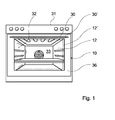
- Figure 1 shows an oven with a arranged in an oven housing 31 Oven muffle 32, which together with a oven door 10 according to the invention a Cooking space 33 limited.
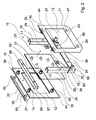
- the oven door 10 has a bar unit 11, a front part forming a front surface 12 and an inner surface forming an inner part 13 ( Figure 2).
- the last unit 11 comprises two side rails 34, 35 formed by U-profiles, which are located at the bottom of the Baking oven door 10 by means of a transverse bar 24 of the strip unit 11 are connected and in installed state with the oven door 10 closed run vertically.
- the crossbar 24 is bolted to the side rails 34, 35, but could also by another, the expert appears useful sense positive, positive and / or cohesive connections to the side rails 34, 35 may be connected.
- hinge units 26, 27 are arranged in the lower region, over which the oven door 10 is pivotally mounted.
- the front part 12 is from an outer visor formed on the front surface of a made of stainless steel aperture 36th glued flat ( Figure 1).
- the inner part 13 is formed by an inner visor.
- the front part 12 and the inner part 13 are made of glass, and basically also other, the expert would appear reasonable as conceivable materials, such as Plastic etc.
- Fastening means 14, 15, 16, 17, 18, 19, 20, 21 for producing a force and Form-fitting connections of four mounting units arranged.
- the fasteners 14, 15, 16, 17, 18, 19, 20, 21 are respectively in the corner regions of the front part 12 or of the inner part 13, in one of the panel 36 covered Border area.
- attachment means 14, 15, 16, 17 on the front part 12 and four fastening means 18, 19, 20, 21 on the inner part 13 can per corner area an advantageous Connection can be achieved, but it is also conceivable, more or less fasteners provided.
- the arranged in the upper region of the front part 12 fasteners 14, 15 are of identical receptacles formed, each through a recess of the front part 12 and extend through a respective recess of the diaphragm 36 and in the insertion direction 22nd over the front surface of the front part 12 and in the insertion direction 23 via an inner surface of the Front part 12 survive ( Figures 2, 5 and 6).
- the fastening means 14, 15 are here in each case via an integrally formed collar 37, 38 by means of an adhesive 43 on the inner surface of the front part 12 glued.
- the fastening means 14, 15 associated fastening means 18, 19 in the upper region of the inner part 13 of the oven door 10 are of identical pin formed, which extend in the direction of insertion 22 to the front part 12 and are in each case via an integrally formed collar 39, 40 by means of an adhesive 44 glued in the direction of the front part 12 facing surface of the inner part 13 ( Figures 2 and 7).
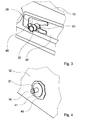
- the arranged in the lower region of the front part 12 fasteners 16, 17 are of identical pin formed, which extend in the direction of insertion 23 to the inner part 13 and are in each case via an integrally formed collar 41, 42 by means of an adhesive 45 the inside of the front part 12 glued ( Figures 2 and 4).
- the fasteners 16, 17 associated fastening means 20, 21 in the lower region of the inner part 13 of the Oven door 10 are formed by identical sockets, which are in the insertion direction 22nd extend to the front part 12, and are in each case via an integrally formed collar 46, 47 means an adhesive, not shown, in the direction of the front part 12 facing surface the inner part 13 glued ( Figures 2 and 3).
- the four mounting units are each one of a plug-in pin and formed by a socket fasteners 14, 15, 16, 17, 18, 19, 20, 21 are formed and are provided for the production of connectors, via which the front part 12 and the inner part 13 are directly coupled in the assembled state. Furthermore, the fastening units for tool-free assembly and disassembly provided by these are designed for the production of locking bonds.
- plug-in sockets trained fastening means 14, 15 in the upper region of the front part 12 in Longitudinal extension of over the inside of the front part 12 protruding part of two make each two opposite, passing through the sleeve wall recesses and formed as receptacles fastener 20, 21 in the Longitudinal at one point two opposite, passing through the sleeve wall Recesses on ( Figures 3 and 5).
- the fastening means 16, 17, 18, 19 designed as plug-in pins each have the Area of its free end a circumferential groove 51, 52 for correspondence with the spring clips 48, 49, 50 on.
- the locking pins 16, 17, 18, 19 are each tapered in the region of their free ends, in the of their fret 39, 40, 41, 42 remote plug-in direction 22, 23 is tapered.
- fasteners 16, 17, 18, 19 are also other, the skilled worker as meaningful appearing fasteners conceivable, such as threaded bolts, etc.
- the oven door 10 has a projecting beyond the front surface of the front part 12 Handle 30 ( Figures 1 and 2).
- Handle 30 On the handle 30 formed by a steel rod are two plug-in pins designed, identical fastening means 53, 54 welded, which are aligned perpendicular to the handle 30 and their shape as the Locking pin trained fasteners 16, 17, 18, 19 correspond.
- the handle 30 of the oven door 10 When mounting the oven door 10, the handle 30 of the oven door 10 is first in a holding device, not shown, with the fastening means 53, 54 perpendicular placed facing up. Subsequently, the front part 12, on the already the panel 36 is glued to the holding device with its front face down placed on and trained as sockets fasteners 14, 15 of the front part 12 on the locking pin formed as a fastening means 53, 54 of the handle 30 in Inserted plug-in direction 22, to the circumferential grooves 55 of the fastening means 53, 54th engage in the previously mounted on the fasteners 14,15 spring clip 50.
- the fastening means 53, 54 are conical, whereby these can be advantageously introduced into the fastening means 14, 15 and one on the other hand, the spring clip 50 when attaching the fastening means 14, 15 on the Fastening means 53, 54 advantageously spring-elastic, can be spread without tools.
- the fastening means 14, 15 thus serve at the same time for attachment of the handle 30th
- clamping means 28, 29 are of formed substantially U-shaped flat springs, in the assembled state, the last unit 11 and the inner part 13 with a perpendicular to the front surface or perpendicular to Inner surface of the inner part 13 acting clamping force in the hinge units 26, 27 tension free play.
- the fastening means 20, 21 thus form part of Clamping unit 25.
- the clamping means 28, 29 are on the fasteners 20, 21 the spring clip 48 mounted by placing these in the opposite recesses the fastening means 20, 21 are inserted laterally.
- the inner part 13 has at the bottom of beveled corner areas, in with the strip unit 11th clamped state parallel to the inner surface of the inner part 13 in a form-fitting manner with substantially triangular contact elements 63, 64 of the strip unit 11 come into contact, which are attached cohesively to the side strips 34, 35.
- elastic tensioning means on the last unit 11 engaged which are provided for generating further clamping forces.
- detent unit of the strip unit 11 is then from a side facing away from the inner part 13 an intermediate visor 62 engaged. It thus creates an inner part 13, the last unit 11 and the intermediate visor 62 comprehensive second assembly unit.
- the second mounting unit is then in Plug-in direction 22 led to the first mounting unit.
- the trained as a plug pin Fasteners 16, 17 thereby engage with their circumferential grooves 51 in the the fasteners 20, 21 fastened spring clip 48 and as plug-in pins trained fasteners 18, 19 thereby engage with their circumferential grooves 52 in the the fastening means 14, 15 fastened, front spring clip 49 a.
- the as plug-in pins trained fasteners 16, 17, 18, 19 may be due to their conical Training advantageous in the form of receptacles formed as fastening means 14, 15, 20, 21 and between the spring clips 48, 49 are inserted through the fastener 16, 17, 18, 19 are spring loaded without tools.
- front part 12 and the handle 30 may also be an alternative front part 12 ' and an alternative handle 30 'are mounted as shown in Fig. 1.
- the Front part 12 ' has with the front part 12 at least substantially identical fastening means and the handle 30 ', with the handle 30 at least substantially identical fastening means, so that the front part 12 'and the handle 30' with the remaining components of the oven door 10 are compatible.
Landscapes
- Engineering & Computer Science (AREA)
- Chemical & Material Sciences (AREA)
- Combustion & Propulsion (AREA)
- Mechanical Engineering (AREA)
- General Engineering & Computer Science (AREA)
- Connection Of Plates (AREA)
- Securing Of Glass Panes Or The Like (AREA)
Applications Claiming Priority (2)
| Application Number | Priority Date | Filing Date | Title |
|---|---|---|---|
| DE200410022967 DE102004022967A1 (de) | 2004-05-10 | 2004-05-10 | Haushaltsgerätetür |
| DE102004022967 | 2004-05-10 |
Publications (2)
| Publication Number | Publication Date |
|---|---|
| EP1596135A2 true EP1596135A2 (fr) | 2005-11-16 |
| EP1596135A3 EP1596135A3 (fr) | 2008-07-30 |
Family
ID=34939763
Family Applications (1)
| Application Number | Title | Priority Date | Filing Date |
|---|---|---|---|
| EP05103870A Withdrawn EP1596135A3 (fr) | 2004-05-10 | 2005-05-10 | Porte d'un appareil ménager |
Country Status (2)
| Country | Link |
|---|---|
| EP (1) | EP1596135A3 (fr) |
| DE (1) | DE102004022967A1 (fr) |
Cited By (2)
| Publication number | Priority date | Publication date | Assignee | Title |
|---|---|---|---|---|
| EP2546576A1 (fr) * | 2011-07-13 | 2013-01-16 | BSH Bosch und Siemens Hausgeräte GmbH | Dispositif dýappareil ménager |
| IT202000023188A1 (it) * | 2020-10-01 | 2022-04-01 | Smeg Spa | Porta di un forno e forno comprendente detta porta |
Families Citing this family (2)
| Publication number | Priority date | Publication date | Assignee | Title |
|---|---|---|---|---|
| DE102007053563A1 (de) * | 2007-11-09 | 2009-05-14 | BSH Bosch und Siemens Hausgeräte GmbH | Scharnierblende |
| DE102009011804B4 (de) * | 2009-03-05 | 2021-03-04 | BSH Hausgeräte GmbH | Hausgerät, insbesondere Backofen |
Citations (3)
| Publication number | Priority date | Publication date | Assignee | Title |
|---|---|---|---|---|
| DE7037721U (de) * | 1971-06-16 | Siemens Gmbh | Tür zum Verschluß von Back und Bratrohren | |
| FR2563612A3 (fr) * | 1984-04-27 | 1985-10-31 | Licentia Gmbh | Porte de four a cuire et a rotir d'un fourneau de cuisine |
| EP0735324A1 (fr) * | 1995-03-24 | 1996-10-02 | Seb S.A. | Porte de four simplifiée avec module amovible |
Family Cites Families (1)
| Publication number | Priority date | Publication date | Assignee | Title |
|---|---|---|---|---|
| DE10143925A1 (de) * | 2001-09-07 | 2003-04-17 | Bsh Bosch Siemens Hausgeraete | Gargerät, Gargerätetür sowie Verfahren zur Herstellung einer Türscheibe für die Gargerätetür |
-
2004
- 2004-05-10 DE DE200410022967 patent/DE102004022967A1/de not_active Withdrawn
-
2005
- 2005-05-10 EP EP05103870A patent/EP1596135A3/fr not_active Withdrawn
Patent Citations (3)
| Publication number | Priority date | Publication date | Assignee | Title |
|---|---|---|---|---|
| DE7037721U (de) * | 1971-06-16 | Siemens Gmbh | Tür zum Verschluß von Back und Bratrohren | |
| FR2563612A3 (fr) * | 1984-04-27 | 1985-10-31 | Licentia Gmbh | Porte de four a cuire et a rotir d'un fourneau de cuisine |
| EP0735324A1 (fr) * | 1995-03-24 | 1996-10-02 | Seb S.A. | Porte de four simplifiée avec module amovible |
Cited By (3)
| Publication number | Priority date | Publication date | Assignee | Title |
|---|---|---|---|---|
| EP2546576A1 (fr) * | 2011-07-13 | 2013-01-16 | BSH Bosch und Siemens Hausgeräte GmbH | Dispositif dýappareil ménager |
| IT202000023188A1 (it) * | 2020-10-01 | 2022-04-01 | Smeg Spa | Porta di un forno e forno comprendente detta porta |
| EP3978809A1 (fr) * | 2020-10-01 | 2022-04-06 | SMEG S.p.A. | Porte de four et four comprenant ladite porte |
Also Published As
| Publication number | Publication date |
|---|---|
| DE102004022967A1 (de) | 2005-12-01 |
| EP1596135A3 (fr) | 2008-07-30 |
Similar Documents
| Publication | Publication Date | Title |
|---|---|---|
| DE102006046908B4 (de) | Wischblattrastvorrichtung | |
| DE4329956C2 (de) | Anordnung zur Halterung eines Einbaukochfeldes | |
| DE102005037020A1 (de) | Vorrichtung mit einer Haushaltsgerätetürträgereinheit | |
| DE102014221784A1 (de) | Haushaltsgerät mit einer Eingabevorrichtung und einer Kodiervorrichtung | |
| DE102006029173A1 (de) | Befestigungseinrichtung für ein Anbauteil | |
| EP1596135A2 (fr) | Porte d'un appareil ménager | |
| WO2012079851A1 (fr) | Dispositif d'essuie-glace | |
| DE2735627A1 (de) | Wischvorrichtung fuer scheiben von kraftfahrzeugen | |
| DE19923487B4 (de) | Widerlager mit Formteil zum Befestigen von Betätigungszügen | |
| DE10143920A1 (de) | Gargerätetür und Scheibenhalteelement für eine Zwischenscheibe | |
| DE202011051645U1 (de) | Möbelboden mit Leuchteneinheit | |
| DE102010019383A1 (de) | Befestigung eines elektronischen Gerätes wie Impedanzwandler oder Verstärker an einer Fahrzeugkarosserie | |
| DE3715435C2 (fr) | ||
| DE102019103964B3 (de) | Haltevorrichtung | |
| DE102008031246A1 (de) | Haushaltsgeräteblendenvorrichtung | |
| EP2420607B1 (fr) | Panneau d'une unité de commande pour un appareil ménager, unité de commande pour un appareil ménager et appareil ménager | |
| EP3213019A1 (fr) | Appareil ménager muni d'un dispositif d'entrée comprenant une feuille flexible | |
| DE102008030786A1 (de) | Ausfachungsrahmen für Gebäudefassaden | |
| DE202008000870U1 (de) | Seitenblende für einen Heizkörper | |
| EP1479978B1 (fr) | Support de panneaux | |
| DE10137842B4 (de) | Bauteil zur Aufnahme in ein Karosserieteil, insbesondere Leuchte | |
| EP3543452A1 (fr) | Joint d'étanchéité de porte pourvu d'un élément de fixation | |
| DE102004052045A1 (de) | Haushaltsgerätetürvorrichtung | |
| DE102010009270A1 (de) | Rastanordnung zur verrastenden Anordnung von zumindest einem ersten Bauteil an zumindest ein zweites Bauteil eines Scheinwerfers | |
| DE102008010500B4 (de) | Hausgerätvorrichtung |
Legal Events
| Date | Code | Title | Description |
|---|---|---|---|
| PUAI | Public reference made under article 153(3) epc to a published international application that has entered the european phase |
Free format text: ORIGINAL CODE: 0009012 |
|
| AK | Designated contracting states |
Kind code of ref document: A2 Designated state(s): AT BE BG CH CY CZ DE DK EE ES FI FR GB GR HU IE IS IT LI LT LU MC NL PL PT RO SE SI SK TR |
|
| AX | Request for extension of the european patent |
Extension state: AL BA HR LV MK YU |
|
| PUAL | Search report despatched |
Free format text: ORIGINAL CODE: 0009013 |
|
| AK | Designated contracting states |
Kind code of ref document: A3 Designated state(s): AT BE BG CH CY CZ DE DK EE ES FI FR GB GR HU IE IS IT LI LT LU MC NL PL PT RO SE SI SK TR |
|
| AX | Request for extension of the european patent |
Extension state: AL BA HR LV MK YU |
|
| 17P | Request for examination filed |
Effective date: 20090130 |
|
| AKX | Designation fees paid |
Designated state(s): AT BE BG CH CY CZ DE DK EE ES FI FR GB GR HU IE IS IT LI LT LU MC NL PL PT RO SE SI SK TR |
|
| 17Q | First examination report despatched |
Effective date: 20141016 |
|
| RAP1 | Party data changed (applicant data changed or rights of an application transferred) |
Owner name: BSH HAUSGERAETE GMBH |
|
| STAA | Information on the status of an ep patent application or granted ep patent |
Free format text: STATUS: THE APPLICATION IS DEEMED TO BE WITHDRAWN |
|
| 18D | Application deemed to be withdrawn |
Effective date: 20141202 |