EP1479978B1 - Support de panneaux - Google Patents
Support de panneaux Download PDFInfo
- Publication number
- EP1479978B1 EP1479978B1 EP04011553.7A EP04011553A EP1479978B1 EP 1479978 B1 EP1479978 B1 EP 1479978B1 EP 04011553 A EP04011553 A EP 04011553A EP 1479978 B1 EP1479978 B1 EP 1479978B1
- Authority
- EP
- European Patent Office
- Prior art keywords
- unit
- panel
- panel holder
- disk
- holding means
- Prior art date
- Legal status (The legal status is an assumption and is not a legal conclusion. Google has not performed a legal analysis and makes no representation as to the accuracy of the status listed.)
- Expired - Lifetime
Links
- 238000010411 cooking Methods 0.000 claims description 13
- 239000002184 metal Substances 0.000 claims description 5
- 230000037431 insertion Effects 0.000 description 4
- 238000003780 insertion Methods 0.000 description 4
- 238000004140 cleaning Methods 0.000 description 1
- 230000001419 dependent effect Effects 0.000 description 1
- 238000009434 installation Methods 0.000 description 1
- 238000004519 manufacturing process Methods 0.000 description 1
Images



Classifications
-
- F—MECHANICAL ENGINEERING; LIGHTING; HEATING; WEAPONS; BLASTING
- F24—HEATING; RANGES; VENTILATING
- F24C—DOMESTIC STOVES OR RANGES ; DETAILS OF DOMESTIC STOVES OR RANGES, OF GENERAL APPLICATION
- F24C15/00—Details
- F24C15/02—Doors specially adapted for stoves or ranges
- F24C15/04—Doors specially adapted for stoves or ranges with transparent panels
Definitions
- the invention is particularly based on a disk holding unit according to the preamble of claim 1.
- the disk holding unit comprises a latching unit, via which a locking connection to a carrier unit can be produced with a mounting movement of the intermediate disk substantially in the direction of its normal.
- the intermediate disk is centered parallel to its surface extension by a centering bevel formed on the disk holding unit.
- the DE195 23 772 A1 relates to a domestic appliance door, in particular an oven door of a baking oven with a door bottom, on the front side of a cover plate is fixed by means of at least one fastening element.
- the EP 1 030 116 A2 describes an oven with a door, consisting of at least one inner pane, an outer pane and two arranged in side areas, parallel extruded profiles, on which the outer pane is fixed, the inner pane for the purpose of cleaning the extruded profiles is solvable.
- the object of the invention is, in particular, to provide a generic disk holding unit in which an increased assembly and disassembly comfort can be achieved with an at least largely play-free centering of a disk.
- the object is achieved by the features of claim 1, while advantageous embodiments and refinements of the invention can be taken from the dependent claims and an independent claim.
- the invention relates to a disk holding unit for at least one first disk, in particular for at least one first intermediate disk of a household appliance, with a latching unit having at least one first holding means, via which a mounting movement the washer is essentially a locking connection produced in the direction of their normal.
- the disk holding unit comprises at least one spring element, via which the disk in the mounted state can be loaded with a spring force substantially parallel to its surface extension.
- the spring element can advantageously deflected during assembly and in particular during disassembly and the assembly and disassembly comfort can be increased.
- an actuating element for deflecting the spring element, and the first holding means of the latching unit can be guided from its detent position. This can advantageously be achieved at least largely tool-free assembly and disassembly of the disc.
- the disk holding unit comprises at least one fastening means for attachment to a carrier unit, which has at least one inclined surface for self-centering in the case of a deflection of the spring element.
- the actuating element may have different shapes that appear appropriate to the person skilled in the art.
- the actuating element is formed by an actuating tab, a simple and economical operation can be achieved in a structurally simple and cost-effective manner.
- the disk holding unit has at least one fastening means designed as a latching means for fastening on a carrier unit.
- a comfortable attachment of the disc in the disc holding unit can also be achieved via a latching connection.
- the pane holding unit could also be fastened to the carrier unit by other non-positive, positive and / or material-locking connections that appear appropriate to a person skilled in the art, for example via welded connections, screw connections, clamping connections, etc.
- the pane holding unit has at least a second holding means for a second pane, whereby additional holding units, installation effort and costs can be saved.
- the pane holding unit comprises at least one stamped-bent sheet-metal part or if it is particularly advantageously formed by a stamped-bent sheet-metal part, a particularly cost-effective Manufacturing can be achieved, in particular by the spring element can be easily integrally integrated into the stamped and bent sheet metal part.
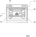
- Fig. 1 shows a baking oven 11 from the front with a cooking chamber 29 delimited by an oven muffle 27 and a cooking appliance door 28.
- the cooking appliance door 28 has an outer pane, an inner pane and two intermediate panes 10, 26.
- the washers 10, 26 are at the lower end of the cooking appliance door 28 between rigid, not shown stops of two lateral support units 18, 18 'at the same and at the upper end of the cooking appliance door 28 via two disk holding units to the support units 18, 18' fixed.
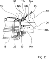
- the disk holding unit is formed by a stamped and bent sheet metal part and comprises a latching unit with two first holding means 12a, 12b for fixing the first intermediate disk 10 and a second holding means 25 for fixing the second intermediate disk 26 (FIG. Fig. 2-5 ).
- About the locking unit is with a mounting movement of the intermediate discs 10, 26 substantially in the direction of their normal 13, a latching connection between the intermediate discs 10, 26 and the disc holding unit produced.
- the second intermediate disc 26 When mounting the second intermediate disc 26, the same, after it is hung on the lower end of the cooking appliance door 28, first comes into contact with insertion bevels 34a, 34b of the first holding means 12a, 12b ( Fig. 2 . 3 . 4 ).
- the first, hook-shaped holding means 12a, 12b and formed as a spring element, flat plate-shaped central part of the disc holding unit are deflected at a continued assembly movement substantially parallel to the surface extension of the second intermediate disc 26, perpendicular to the longitudinal extent of the support unit 18 in the direction away from the second washer 26 direction , If the second intermediate disk 26 has crossed the first holding means 12a, 12b, they engage behind the second intermediate disk 26.
- the second intermediate disc 26 comes with an insertion bevel 35 of the second holding means 25 in abutment.
- the second holding means 25 and the spring element arranged in the longitudinal direction of the carrier unit 18 between the first holding means 12a, 12b and in the mounting direction behind the first holding means 12a, 12b are in turn parallel to the surface extension of the second intermediate plate 26, perpendicular to the longitudinal extent of the carrier unit 18, in the the intermediate disc 26 deflected away direction. If the second intermediate plate 26 has crossed the second holding means 25, the second holding means 25 engages behind the second intermediate plate 26.
- the second intermediate disc 26 is viewed with the cooking appliance door 28 closed, supported between the upper end of the support unit 18 and the lower end of the support unit 18 to a stop 39 of the support unit 18 and is biased during assembly arcuately about a horizontally extending axis.
- the intermediate discs 10, 26 are shown schematically in a side view with an exaggerated curvature.
- the second intermediate disc 26 is loaded by the spring element of the disc holding unit in the mounted state substantially parallel to its surface extension, perpendicular to the longitudinal extension of the carrier unit 18 in the direction away from the same with a spring force 14b.
- the first intermediate plate 10 When mounting the first intermediate plate 10, the same, after it is hung on the lower end of the cooking appliance door 28, first comes into contact with the introduction bevels 34a, 34b of the first holding means 12a, 12b ( Fig. 2 . 3 . 4 ). Subsequently, the first holding means 12a, 12b and the spring element of the disk holding unit in a continued assembly movement substantially parallel to the surface extension of the first intermediate disc 10, perpendicular to the longitudinal extent of the support unit 18, deflected in the direction away from the first intermediate disc 10 direction. If the first intermediate disk 10 has crossed the first holding means 12a, 12b, the first holding means 12a, 12b engage behind the first intermediate disk 10.
- the first intermediate disc 10 is, viewed with the cooking appliance door 28 closed, supported between the upper end of the support unit 18 and the lower end of the support unit 18 on a stop 38 and is biased according to the second washer 26 during assembly arcuately about a horizontally extending axis ( Fig. 1a ).
- the first intermediate disc 10 is loaded by the spring element of the disc holding unit in the mounted state substantially parallel to its surface extension, perpendicular to the longitudinal extension of the carrier unit 18 in the direction away from the same with a spring force 14a.
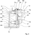
- the spring element is deflected and biased after assembly of the intermediate discs 10, 26, as shown in Fig. 3 can be seen, in which a contact surface 37 of the disk holding unit before and after the assembly of the intermediate plates 10, 26 is shown, wherein the contact surface 37 * is shown in phantom prior to assembly.
- the disk holding unit Due to the deflection of the spring element, the disk holding unit is also fixed to the support unit 18 without play, so that a total of at least largely play-free mounting of the intermediate disks 10, 26 is achieved.
- the disk holding unit is mounted on a first, in the longitudinal direction of the support unit 18 facing side via two tab-shaped fastening means 19, 20 in recesses 30, 31 of the support unit 18 and is on a first side opposite the second side via two locking means formed as a U-shaped curved Fastening means 16, 17 in two further recesses 32, 33 of the support unit 18 is engaged ( Fig. 3 and 5 ).
- the fastening means 16, 17, 19, 20 for fastening the pane holding unit to the carrier unit 18 each have a conical contour with inclined surfaces 21a, 21b, 22a, 22b, 23a, 23b, 24a, 24b for self-centering in the recesses 30, 31, 32, 33 at a deflection of the Spring element on. If the spring element deflected, the fastening means 16, 17, 19, 20 are further inserted into the recesses 30, 31, 32, 33 and are centered by their conical contour in the recesses 30, 31, 32, 33 at least substantially free of play.
- the disk holding unit has a formed as an actuating tab, integrally molded, tab-shaped actuating element 15th on, over which the holding means 12a, 12b, 25 of the locking unit can be guided from their locking positions.
- a recess 36 is provided between the recesses 30, 31, 32, 33 of the support unit 18 in the same.
Landscapes
- Engineering & Computer Science (AREA)
- Chemical & Material Sciences (AREA)
- Combustion & Propulsion (AREA)
- Mechanical Engineering (AREA)
- General Engineering & Computer Science (AREA)
- Baking, Grill, Roasting (AREA)
- Pivots And Pivotal Connections (AREA)
Claims (6)
- Unité de maintien de rondelle pour au moins une première rondelle (10), en particulier pour au moins la première rondelle intermédiaire (10) d'un appareil électroménager (11) avec une unité d'encliquetage présentant au moins un premier moyen de maintien (12a, 12b), par le biais de laquelle, par un mouvement de montage de la rondelle (10) essentiellement dans le sens de sa normale (13), un raccord par encliquetage peut être constitué, l'unité de maintien de rondelle comprenant au moins un élément à ressort par lequel la rondelle (10) peut être sollicitée, à l'état monté, essentiellement en parallèle de son élongation superficielle avec une force de ressort (14a),
caractérisée par au moins un élément d'actionnement (15) pour l'articulation de l'élément à ressort, le premier moyen de maintien (12a, 12b) de l'unité d'encliquetage pouvant quitter sa position d'encliquetage grâce à l'élément d'actionnement (15); et au moins un élément de fixation (16, 17, 19, 20) servant à la fixation sur une unité de support (18) qui présente au moins une surface oblique (21a, 21b, 22a, 22b, 23a, 23b, 24a, 24b) pour auto-centrage en cas d'articulation de l'élément à ressort. - Unité de maintien de rondelle selon la revendication 1, caractérisée en ce que l'élément d'actionnement (15) est formé d'une languette d'actionnement.
- Unité de maintien de rondelle selon l'une des revendications précédentes, caractérisée par au moins un moyen de fixation (16, 17) configuré comme un moyen d'encliquetage, pour la fixation sur une unité de support (18).
- Unité de maintien de rondelle selon l'une des revendications précédentes, caractérisée par au moins un deuxième moyen de maintien (25) pour une deuxième rondelle (26).
- Unité de maintien de rondelle selon l'une des revendications précédentes, caractérisée par au moins une pièce tôlée de découpage pliage.
- Porte d'appareil de cuisson avec une unité de maintien de rondelle selon l'une des revendications précédentes.
Applications Claiming Priority (2)
| Application Number | Priority Date | Filing Date | Title |
|---|---|---|---|
| DE10323192 | 2003-05-22 | ||
| DE10323192A DE10323192A1 (de) | 2003-05-22 | 2003-05-22 | Scheibenhalteeinheit |
Publications (3)
| Publication Number | Publication Date |
|---|---|
| EP1479978A2 EP1479978A2 (fr) | 2004-11-24 |
| EP1479978A3 EP1479978A3 (fr) | 2015-12-30 |
| EP1479978B1 true EP1479978B1 (fr) | 2019-04-10 |
Family
ID=33039271
Family Applications (1)
| Application Number | Title | Priority Date | Filing Date |
|---|---|---|---|
| EP04011553.7A Expired - Lifetime EP1479978B1 (fr) | 2003-05-22 | 2004-05-14 | Support de panneaux |
Country Status (2)
| Country | Link |
|---|---|
| EP (1) | EP1479978B1 (fr) |
| DE (1) | DE10323192A1 (fr) |
Families Citing this family (2)
| Publication number | Priority date | Publication date | Assignee | Title |
|---|---|---|---|---|
| FR2934671B1 (fr) * | 2008-07-29 | 2010-09-03 | Fagorbrandt Sas | Procede d'assemblage d'une porte pour enceinte de cuisson |
| DE102020209242A1 (de) | 2020-07-22 | 2022-01-27 | BSH Hausgeräte GmbH | Tür und Haushaltsgargerät |
Family Cites Families (7)
| Publication number | Priority date | Publication date | Assignee | Title |
|---|---|---|---|---|
| DE19523772A1 (de) * | 1995-06-29 | 1997-01-02 | Bosch Siemens Hausgeraete | Hausgeräte-Tür, vorzugsweise Ofentür eines Backofens |
| DE19853758C2 (de) * | 1998-11-21 | 2001-10-18 | Ege Elektro Gmbh | Backofentür mit Sichtfenster und Betätigungshandgriff |
| DE19906747A1 (de) * | 1999-02-17 | 2000-08-24 | Imp Werke Gmbh & Co | Backofen |
| DE29914007U1 (de) * | 1999-08-11 | 1999-10-21 | AEG Hausgeräte GmbH, 90429 Nürnberg | Tür für ein Gerät, insbesondere einen Garofen, mit unverwechselbar montierbaren Scheiben |
| FR2828556A1 (fr) * | 2001-08-08 | 2003-02-14 | Moulinex Sa | Porte de four menager |
| DE10143920A1 (de) * | 2001-09-07 | 2003-04-17 | Bsh Bosch Siemens Hausgeraete | Gargerätetür und Scheibenhalteelement für eine Zwischenscheibe |
| DE10143926B4 (de) | 2001-09-07 | 2004-06-24 | BSH Bosch und Siemens Hausgeräte GmbH | Gargerätetür |
-
2003
- 2003-05-22 DE DE10323192A patent/DE10323192A1/de not_active Withdrawn
-
2004
- 2004-05-14 EP EP04011553.7A patent/EP1479978B1/fr not_active Expired - Lifetime
Non-Patent Citations (1)
| Title |
|---|
| None * |
Also Published As
| Publication number | Publication date |
|---|---|
| EP1479978A3 (fr) | 2015-12-30 |
| DE10323192A1 (de) | 2004-12-09 |
| EP1479978A2 (fr) | 2004-11-24 |
Similar Documents
| Publication | Publication Date | Title |
|---|---|---|
| EP1076622B1 (fr) | Raclette d'essuie-glace servant a nettoyer des vitres de vehicules et son procede de montage | |
| EP1337419B1 (fr) | Dispositif de fixation liberable d'un essuie-glace pour le nettoyage de vitres, en particulier de vehicules a moteur, sur un bras d'essuie-glace | |
| EP1494903A1 (fr) | Levier d'essuie-glace muni d'un bras d'essuie-glace commande et d'un balai d'essuie-glace articule dessus, pour nettoyer des vitres, en particulier d'automobiles | |
| EP1735194A1 (fr) | Systeme d'essuie-glace, notamment pour vehicule automobile | |
| DE10130903A1 (de) | Vorrichtung zum lösbaren Verbinden eines Wischblatts zum Reinigen von Scheiben insbesondere von Kraftfahrzeugen mit einem angetriebenen Wischerarm | |
| WO1996022205A1 (fr) | Raclette d'essuie-glace | |
| EP1590606B1 (fr) | Dispositif de support, conçu en particulier pour un appareil de cuisson | |
| DE10043427B4 (de) | Wischvorrichtung | |
| EP0757636B1 (fr) | Deflecteur pour balai d'essuie-glace | |
| DE4218425A1 (de) | Befestigung für eine Fensterscheibe an einem Fensterheber | |
| EP1902257B1 (fr) | Dispositif de tablette coulissante | |
| EP1479978B1 (fr) | Support de panneaux | |
| EP0709267B1 (fr) | Dispositif d'essuie-glaces de véhicules automobiles | |
| EP0900987B1 (fr) | Porte pour un appareil ménager, notamment pour un four ménager pour la cuisson à point | |
| DE10143920A1 (de) | Gargerätetür und Scheibenhalteelement für eine Zwischenscheibe | |
| DE8412965U1 (de) | Tuer fuer den back- und bratraum eines bratofens | |
| DE102005033225B4 (de) | Hausgerätetürelement und Backofentür mit einem solchen Hausgerätetürelement | |
| DE202004013917U1 (de) | Gargerätemuffel | |
| DE102008031246A1 (de) | Haushaltsgeräteblendenvorrichtung | |
| DE10227996A1 (de) | Getriebe-Antriebseinheit mit Rastelement | |
| EP1225092B1 (fr) | Miroir d'automobile | |
| EP1769970B1 (fr) | Système de fixation | |
| DE102004061889A1 (de) | Auszugsvorrichtung | |
| EP1215443A2 (fr) | Dispositif de retenue pour au moins une vitre de porte, en particulier pour une vitre de porte de four | |
| DE19616157C2 (de) | Türfeststeller insbesondere für Automobile |
Legal Events
| Date | Code | Title | Description |
|---|---|---|---|
| PUAI | Public reference made under article 153(3) epc to a published international application that has entered the european phase |
Free format text: ORIGINAL CODE: 0009012 |
|
| AK | Designated contracting states |
Kind code of ref document: A2 Designated state(s): AT BE BG CH CY CZ DE DK EE ES FI FR GB GR HU IE IT LI LU MC NL PL PT RO SE SI SK TR |
|
| AX | Request for extension of the european patent |
Extension state: AL HR LT LV MK |
|
| RAP1 | Party data changed (applicant data changed or rights of an application transferred) |
Owner name: BSH HAUSGERAETE GMBH |
|
| PUAL | Search report despatched |
Free format text: ORIGINAL CODE: 0009013 |
|
| AK | Designated contracting states |
Kind code of ref document: A3 Designated state(s): AT BE BG CH CY CZ DE DK EE ES FI FR GB GR HU IE IT LI LU MC NL PL PT RO SE SI SK TR |
|
| AX | Request for extension of the european patent |
Extension state: AL HR LT LV MK |
|
| RIC1 | Information provided on ipc code assigned before grant |
Ipc: F24C 15/04 20060101AFI20151123BHEP |
|
| 17P | Request for examination filed |
Effective date: 20160630 |
|
| RBV | Designated contracting states (corrected) |
Designated state(s): AT BE BG CH CY CZ DE DK EE ES FI FR GB GR HU IE IT LI LU MC NL PL PT RO SE SI SK TR |
|
| AKX | Designation fees paid |
Designated state(s): AT BE BG CH CY CZ DE DK EE ES FI FR GB GR HU IE IT LI LU MC NL PL PT RO SE SI SK TR |
|
| AXX | Extension fees paid |
Extension state: HR Extension state: LT Extension state: LV Extension state: AL Extension state: MK |
|
| STAA | Information on the status of an ep patent application or granted ep patent |
Free format text: STATUS: EXAMINATION IS IN PROGRESS |
|
| 17Q | First examination report despatched |
Effective date: 20170526 |
|
| GRAP | Despatch of communication of intention to grant a patent |
Free format text: ORIGINAL CODE: EPIDOSNIGR1 |
|
| STAA | Information on the status of an ep patent application or granted ep patent |
Free format text: STATUS: GRANT OF PATENT IS INTENDED |
|
| INTG | Intention to grant announced |
Effective date: 20181116 |
|
| RIC1 | Information provided on ipc code assigned before grant |
Ipc: F24C 15/04 20060101AFI20151123BHEP |
|
| GRAS | Grant fee paid |
Free format text: ORIGINAL CODE: EPIDOSNIGR3 |
|
| GRAA | (expected) grant |
Free format text: ORIGINAL CODE: 0009210 |
|
| STAA | Information on the status of an ep patent application or granted ep patent |
Free format text: STATUS: THE PATENT HAS BEEN GRANTED |
|
| AK | Designated contracting states |
Kind code of ref document: B1 Designated state(s): AT BE BG CH CY CZ DE DK EE ES FI FR GB GR HU IE IT LI LU MC NL PL PT RO SE SI SK TR |
|
| REG | Reference to a national code |
Ref country code: GB Ref legal event code: FG4D Free format text: NOT ENGLISH |
|
| REG | Reference to a national code |
Ref country code: CH Ref legal event code: EP Ref country code: AT Ref legal event code: REF Ref document number: 1119210 Country of ref document: AT Kind code of ref document: T Effective date: 20190415 |
|
| REG | Reference to a national code |
Ref country code: DE Ref legal event code: R096 Ref document number: 502004015781 Country of ref document: DE |
|
| REG | Reference to a national code |
Ref country code: IE Ref legal event code: FG4D Free format text: LANGUAGE OF EP DOCUMENT: GERMAN |
|
| REG | Reference to a national code |
Ref country code: NL Ref legal event code: MP Effective date: 20190410 |
|
| PG25 | Lapsed in a contracting state [announced via postgrant information from national office to epo] |
Ref country code: NL Free format text: LAPSE BECAUSE OF FAILURE TO SUBMIT A TRANSLATION OF THE DESCRIPTION OR TO PAY THE FEE WITHIN THE PRESCRIBED TIME-LIMIT Effective date: 20190410 |
|
| PG25 | Lapsed in a contracting state [announced via postgrant information from national office to epo] |
Ref country code: ES Free format text: LAPSE BECAUSE OF FAILURE TO SUBMIT A TRANSLATION OF THE DESCRIPTION OR TO PAY THE FEE WITHIN THE PRESCRIBED TIME-LIMIT Effective date: 20190410 Ref country code: FI Free format text: LAPSE BECAUSE OF FAILURE TO SUBMIT A TRANSLATION OF THE DESCRIPTION OR TO PAY THE FEE WITHIN THE PRESCRIBED TIME-LIMIT Effective date: 20190410 Ref country code: PT Free format text: LAPSE BECAUSE OF FAILURE TO SUBMIT A TRANSLATION OF THE DESCRIPTION OR TO PAY THE FEE WITHIN THE PRESCRIBED TIME-LIMIT Effective date: 20190910 Ref country code: SE Free format text: LAPSE BECAUSE OF FAILURE TO SUBMIT A TRANSLATION OF THE DESCRIPTION OR TO PAY THE FEE WITHIN THE PRESCRIBED TIME-LIMIT Effective date: 20190410 |
|
| PG25 | Lapsed in a contracting state [announced via postgrant information from national office to epo] |
Ref country code: PL Free format text: LAPSE BECAUSE OF FAILURE TO SUBMIT A TRANSLATION OF THE DESCRIPTION OR TO PAY THE FEE WITHIN THE PRESCRIBED TIME-LIMIT Effective date: 20190410 Ref country code: GR Free format text: LAPSE BECAUSE OF FAILURE TO SUBMIT A TRANSLATION OF THE DESCRIPTION OR TO PAY THE FEE WITHIN THE PRESCRIBED TIME-LIMIT Effective date: 20190711 Ref country code: BG Free format text: LAPSE BECAUSE OF FAILURE TO SUBMIT A TRANSLATION OF THE DESCRIPTION OR TO PAY THE FEE WITHIN THE PRESCRIBED TIME-LIMIT Effective date: 20190710 |
|
| REG | Reference to a national code |
Ref country code: DE Ref legal event code: R119 Ref document number: 502004015781 Country of ref document: DE |
|
| REG | Reference to a national code |
Ref country code: CH Ref legal event code: PL |
|
| PG25 | Lapsed in a contracting state [announced via postgrant information from national office to epo] |
Ref country code: MC Free format text: LAPSE BECAUSE OF FAILURE TO SUBMIT A TRANSLATION OF THE DESCRIPTION OR TO PAY THE FEE WITHIN THE PRESCRIBED TIME-LIMIT Effective date: 20190410 Ref country code: SK Free format text: LAPSE BECAUSE OF FAILURE TO SUBMIT A TRANSLATION OF THE DESCRIPTION OR TO PAY THE FEE WITHIN THE PRESCRIBED TIME-LIMIT Effective date: 20190410 Ref country code: LI Free format text: LAPSE BECAUSE OF NON-PAYMENT OF DUE FEES Effective date: 20190531 Ref country code: CZ Free format text: LAPSE BECAUSE OF FAILURE TO SUBMIT A TRANSLATION OF THE DESCRIPTION OR TO PAY THE FEE WITHIN THE PRESCRIBED TIME-LIMIT Effective date: 20190410 Ref country code: RO Free format text: LAPSE BECAUSE OF FAILURE TO SUBMIT A TRANSLATION OF THE DESCRIPTION OR TO PAY THE FEE WITHIN THE PRESCRIBED TIME-LIMIT Effective date: 20190410 Ref country code: EE Free format text: LAPSE BECAUSE OF FAILURE TO SUBMIT A TRANSLATION OF THE DESCRIPTION OR TO PAY THE FEE WITHIN THE PRESCRIBED TIME-LIMIT Effective date: 20190410 Ref country code: CH Free format text: LAPSE BECAUSE OF NON-PAYMENT OF DUE FEES Effective date: 20190531 Ref country code: DK Free format text: LAPSE BECAUSE OF FAILURE TO SUBMIT A TRANSLATION OF THE DESCRIPTION OR TO PAY THE FEE WITHIN THE PRESCRIBED TIME-LIMIT Effective date: 20190410 |
|
| REG | Reference to a national code |
Ref country code: BE Ref legal event code: MM Effective date: 20190531 |
|
| PLBE | No opposition filed within time limit |
Free format text: ORIGINAL CODE: 0009261 |
|
| STAA | Information on the status of an ep patent application or granted ep patent |
Free format text: STATUS: NO OPPOSITION FILED WITHIN TIME LIMIT |
|
| PG25 | Lapsed in a contracting state [announced via postgrant information from national office to epo] |
Ref country code: LU Free format text: LAPSE BECAUSE OF NON-PAYMENT OF DUE FEES Effective date: 20190514 Ref country code: IT Free format text: LAPSE BECAUSE OF FAILURE TO SUBMIT A TRANSLATION OF THE DESCRIPTION OR TO PAY THE FEE WITHIN THE PRESCRIBED TIME-LIMIT Effective date: 20190410 |
|
| 26N | No opposition filed |
Effective date: 20200113 |
|
| GBPC | Gb: european patent ceased through non-payment of renewal fee |
Effective date: 20190710 |
|
| PG25 | Lapsed in a contracting state [announced via postgrant information from national office to epo] |
Ref country code: TR Free format text: LAPSE BECAUSE OF FAILURE TO SUBMIT A TRANSLATION OF THE DESCRIPTION OR TO PAY THE FEE WITHIN THE PRESCRIBED TIME-LIMIT Effective date: 20190410 |
|
| PG25 | Lapsed in a contracting state [announced via postgrant information from national office to epo] |
Ref country code: IE Free format text: LAPSE BECAUSE OF NON-PAYMENT OF DUE FEES Effective date: 20190514 Ref country code: GB Free format text: LAPSE BECAUSE OF NON-PAYMENT OF DUE FEES Effective date: 20190710 Ref country code: DE Free format text: LAPSE BECAUSE OF NON-PAYMENT OF DUE FEES Effective date: 20191203 |
|
| PG25 | Lapsed in a contracting state [announced via postgrant information from national office to epo] |
Ref country code: BE Free format text: LAPSE BECAUSE OF NON-PAYMENT OF DUE FEES Effective date: 20190531 Ref country code: SI Free format text: LAPSE BECAUSE OF FAILURE TO SUBMIT A TRANSLATION OF THE DESCRIPTION OR TO PAY THE FEE WITHIN THE PRESCRIBED TIME-LIMIT Effective date: 20190410 |
|
| PG25 | Lapsed in a contracting state [announced via postgrant information from national office to epo] |
Ref country code: FR Free format text: LAPSE BECAUSE OF NON-PAYMENT OF DUE FEES Effective date: 20190610 |
|
| REG | Reference to a national code |
Ref country code: AT Ref legal event code: MM01 Ref document number: 1119210 Country of ref document: AT Kind code of ref document: T Effective date: 20190514 |
|
| PG25 | Lapsed in a contracting state [announced via postgrant information from national office to epo] |
Ref country code: AT Free format text: LAPSE BECAUSE OF NON-PAYMENT OF DUE FEES Effective date: 20190514 |
|
| PG25 | Lapsed in a contracting state [announced via postgrant information from national office to epo] |
Ref country code: CY Free format text: LAPSE BECAUSE OF FAILURE TO SUBMIT A TRANSLATION OF THE DESCRIPTION OR TO PAY THE FEE WITHIN THE PRESCRIBED TIME-LIMIT Effective date: 20190410 |
|
| PG25 | Lapsed in a contracting state [announced via postgrant information from national office to epo] |
Ref country code: HU Free format text: LAPSE BECAUSE OF FAILURE TO SUBMIT A TRANSLATION OF THE DESCRIPTION OR TO PAY THE FEE WITHIN THE PRESCRIBED TIME-LIMIT; INVALID AB INITIO Effective date: 20040514 |