EP0900987B1 - Porte pour un appareil ménager, notamment pour un four ménager pour la cuisson à point - Google Patents
Porte pour un appareil ménager, notamment pour un four ménager pour la cuisson à point Download PDFInfo
- Publication number
- EP0900987B1 EP0900987B1 EP98112783A EP98112783A EP0900987B1 EP 0900987 B1 EP0900987 B1 EP 0900987B1 EP 98112783 A EP98112783 A EP 98112783A EP 98112783 A EP98112783 A EP 98112783A EP 0900987 B1 EP0900987 B1 EP 0900987B1
- Authority
- EP
- European Patent Office
- Prior art keywords
- receiving
- inner panel
- receiving device
- door
- door according
- Prior art date
- Legal status (The legal status is an assumption and is not a legal conclusion. Google has not performed a legal analysis and makes no representation as to the accuracy of the status listed.)
- Expired - Lifetime
Links
Images

Classifications
-
- F—MECHANICAL ENGINEERING; LIGHTING; HEATING; WEAPONS; BLASTING
- F24—HEATING; RANGES; VENTILATING
- F24C—DOMESTIC STOVES OR RANGES ; DETAILS OF DOMESTIC STOVES OR RANGES, OF GENERAL APPLICATION
- F24C15/00—Details
- F24C15/02—Doors specially adapted for stoves or ranges
- F24C15/04—Doors specially adapted for stoves or ranges with transparent panels
Definitions
- the invention relates to a door for a household appliance, especially a household oven
- Doors for household ovens are known with a viewing window, that through a translucent outer pane and a translucent inner pane and possibly also a translucent washer arranged between them is formed.
- Windows in the door are a variety of options known.
- a furnace door according to US 2,514,590 has a frame insert structure on, the transparent panes, their mutual Distance secured by intermediate springs is, absorbs and in its entirety against the force second springs can be used in a door structure.
- This font shows the feature groups a, b, e, f and partially h in claim 1.
- the invention has for its object a door for a Household appliance, in particular a household oven, with at least one at least partially translucent Specify door window where the door window is without tools simply assembled and, for example for cleaning purposes, can be removed.
- the inner pane can be used without tools simply by hand into the door mounting devices used or removed from these.
- the inner pane When assembling the inner pane is the inner pane in the first receiving device, generally against the restoring force the reset device, until it is also inserted into the receiving groove or other receiving the second receiving device can be introduced. If the inner pane now directly in front of the opening of the second recording device it is replaced by the resetting Force of the resetting device of the first receiving device pushed into the receiving groove of the second receiving device and held there (locked, fixed). To take out the inner pane is simply the inner pane again against the restoring force of the restoring device in the first recording device pressed until it out the receiving groove of the second receiving device emerges and can then simply from the first recording device be removed.
- the door has at least two support elements which are connected to the outer pane and on which the two Receiving devices for the inner pane are attached.
- the two carrier elements can in particular be an actuating handle wear, which is also at least part of one of the forms two receiving devices for the inner pane.
- the reset device of the first receiving device comprise at least one spring element, the elastic deformation by the door window a restoring Power causes.
- Reset devices such as pneumatic or electromagnetic devices can be provided, in particular can be operated by a switch.
- the first mounting device comprises this first receiving device preferably at least one lateral guide in the direction of insertion for the door window that with the spring element itself or an additional component can be formed.
- the door glass is essentially rectangular educated.
- the second receiving device can then to hold one corner of the door pane at a time have an angular receiving part (holding corner).
- the door is preferably used for locking the loading opening of a muffle in a household oven.
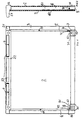
- the inner pane 2 and the outer pane 3 are preferred rectangular shape, the inner pane 2 slightly smaller than the outer pane 3 is formed.
- the two Carrier elements 5 and 6 each have a columnar shape Middle part 51 or 61 and two laterally from the middle part 51 and 61 protruding flange edges 50 and 60 on and can be formed in particular from U-shaped profiled sheet metal his.
- the flange edges 50 and 60 are the two Carrier elements 5 and 6 each glued to the outer pane 3. Due to the comparatively large adhesive surface Forces from the support elements 5 and 6 evenly on the Transfer outer pane 3 so that the outer pane shatters 3 due to thermal or mechanical stresses is practically avoided.
- the adhesive connection ensures moreover a gentle connection of the carrier elements 5 and 6 with the outer pane 3 during manufacture. However, it can also a screw connection or another connection the carrier elements 5 and 6 are provided with the outer pane 3 his.
- a door handle 21 In an upper area of the door is on the support elements 5 and 6 a door handle 21 attached.
- the door handle 21 has a stop area 22 that overlaps the inner pane 2 on. Between this stop area 22 and the contact surfaces the carrier elements 5 and 6 is the inner pane 2 held in their upper area.
- the one between the extreme Edge of the stop area 22 and the carrier element 5 or 6 formed receiving opening (receiving gap) for the Inner pane 2 is designated by 24.
- the attack area 22 is in the illustrated embodiment over the whole Width of the inner pane 2 is formed.
- the door handle 21 has one above the stop area 22 or several air outlets for out of the oven escaping cooling air. Below these openings 23 is now a spring element 4 is arranged behind the stop region 22, on the inner pane 2 when inserting the inner pane 2 exerts a restoring force.
- the spring element 4 can in particular be formed with a metal sheet be a spring tongue directed towards the inner pane 2 has and preferably also over the whole Width of the stop region 22 extends.
- the spring tongue of the spring element 4 is between a starting position in a distance L3 from the receiving opening 24 at the end of the stop area 22 to the end position at a distance L1 > L3 deflectable from the receiving opening 24 and exercises depending a restoring force from its deflection on the inner pane 2.
- the stop area 22, the support elements 5 and 6 and the spring element 4 together form a first receiving device for receiving the inner pane 2 with the receiving opening 24th
- each of the two support elements the lower areas of which each have a receiving part 7 and 8 attached to the inner pane 2, in particular screwed or releasably engaged or clamped.
- the two Receiving parts 7 and 8 form a common second receiving device for the inner pane 2 and preferably exist from a plastic.
- Each of the two lower corners the inner pane 2 is in a corresponding, angular Area of the associated receiving part 7 or 8 fitted, the inner pane 2 at each corner at one vertical stop 70 or 80 and a horizontal stop 71 or 81 abuts and thus to the inside, i.e. towards the oven muffle, is secured against falling out.
- the inner pane 2 can now be installed in the door as follows or be taken out of the door.
- the first receiving device is inserted around an insertion path, which is larger than L2 and upwards by the maximum Insertion path L1 is limited.
- the spring element 4 excited.
- the inner pane 2 is now centered that they are in the receiving grooves 72 and 82 of the second receiving device under the restoring force of the spring element 4 - and also gravity in the illustrated Embodiment - can snap.
- the spring element 4 holds the inner pane 2 under a certain force in the second receiving device so that the inner pane 2 is secure is fixed.
- To remove the inner pane 2 the inner pane 2 again against the restoring force of spring element 4 pressed into the first receiving device and then removed from the receiving grooves 72 and 82.
- FIG. 3 additionally shows one not shown in FIGS. 1 and 2 Shim 14 shown between the outer pane 3 and the inner pane 2 and between the two Carrier elements 5 and 6 is inserted into the door.
- This Intermediate disc 14 preferably has inserted or sprayed Frame elements (frame parts, edge parts) 93 and 94 preferably made of plastic.
- On the frame elements 93 and 94 are a plurality of spacers 15 and 17 for holding one Distance between the intermediate plate 14 and the inner plate 2 on the one hand and on the opposite Side spacers 16 and 18 for keeping a distance between the intermediate disc 14 and the outer disc 3 provided.
- the spacers 15 to 18 on the frame elements 93 and 94 can in particular be a round, preferably have a semicircular shape.
- the spacer 14 can each have three spacers be provided at the front and rear. If the washer 14 with the inner pane 2 removed now on the spacers 16 and 18 along the inner flange edges 51 and 61 the carrier elements 5 and 6 or the outer pane 3 in Is pushed towards handle 21, it will be on one in upper contours running across the door (guide link) 90 lifted up. The then sloping The intermediate disc 14 can now easily be removed from the door be used, especially for cleaning purposes. Furthermore are on the frame elements 93 and 94 of the washer 14 stops 91 and 92 provided with which the washer 14 on corresponding contact surfaces on the receiving parts 7 and 8 sits on.
- Receiving parts 7 and 8 is an opening 51 and 61 provided for carrying components for movement the door in particular door hinge or baking cart pull-out parts, which then into the internally hollow support element 5 or 6th inserted and locked there.
- the receiving grooves can also in all embodiments at least partially replaced by other receiving elements are, for example brackets, two-leg springs.
Landscapes
- Engineering & Computer Science (AREA)
- Chemical & Material Sciences (AREA)
- Combustion & Propulsion (AREA)
- Mechanical Engineering (AREA)
- General Engineering & Computer Science (AREA)
- Electric Ovens (AREA)
- Securing Of Glass Panes Or The Like (AREA)
Claims (7)
- Porte pour un appareil ménager, notamment pour un four ménager comprenant :a) une plaque extérieure au moins partiellement optiquement transparente (3),b) une plaque intérieure au moins partiellement optiquement transparente (2) à un côté éloigné de la plaque extérieure,c) au moins deux éléments de support (5, 6) fixés à la plaque extérieure (3),d) une poignée d'actionnement (21) fixée aux deux éléments de support (5, 6),e) une première installation de réception avec au moins une ouverture (24) pour la réception de la plaque intérieure (12) et une deuxième installation de réception (72, 82) avec au moins une ouverture, de préférence une rainure de réception, pour la réception de la plaque intérieure, oùf) les deux installations de réception pour la plaque intérieure (2) sont fixées aux deux éléments de support (5, 6),g) la poignée d'actionnement (21) constitue au moins une partie d'une des deux installations de réception de la plaque intérieure (2),h) les ouvertures des deux installations de réception présentent un écart plus petit d'une longueur de chemin d'insertion minimale prédéterminée que la dimension correspondante de la plaque intérieure (2),i) la plaque intérieure (2) est insérable dans la première installation de réception selon au moins la longueur de chemin d'insertion minimale prédéterminée etj) au moins la première installation de réception présente une installation de rappel (4) pour exercer une force de rappel de telle sorte que la plaque intérieure (2), après l'insertion dans la première installation de réception selon au moins la longueur de chemin d'insertion minimale prédéterminée est poussée par la force de rappel de l'installation de rappel (4) dans la deuxième installation de réception (72, 82).
- Porte selon la revendication 1, où l'installation de rappel de la première installation de réception comprend au moins un élément à ressort (4).
- Porte selon la revendication 1 ou la revendication 2, où la première installation de réception comprend au moins un guidage latéral pour la plaque intérieure (2) dans la direction d'insertion.
- Porte selon l'une des revendications précédentes, où la plaque intérieure (2) est réalisée d'une manière sensiblement rectangulaire.
- Porte selon la revendication 4, où la deuxième installation de réception (72, 82) présente deux parties de réception associées à des coins avoisinants de la plaque intérieure (2), s'étendant en forme d'angle.
- Porte selon l'une des revendications précédentes avec une plaque intermédiaire additionnelle au moins partiellement optiquement transparente entre la plaque extérieure (3) et la plaque intérieure (2).
- Four ménager aveca) un moufle de four avec une ouverture de chargement pour l'introduction d'aliments à cuire etb) une porte selon l'une des revendications précédentes pour fermer le moufle de four.
Applications Claiming Priority (2)
| Application Number | Priority Date | Filing Date | Title |
|---|---|---|---|
| DE19738504A DE19738504C5 (de) | 1997-09-03 | 1997-09-03 | Tür für ein Haushaltsgerät, insbesondere einen Haushaltsgarofen |
| DE19738504 | 1997-09-03 |
Publications (2)
| Publication Number | Publication Date |
|---|---|
| EP0900987A1 EP0900987A1 (fr) | 1999-03-10 |
| EP0900987B1 true EP0900987B1 (fr) | 2002-10-16 |
Family
ID=7841070
Family Applications (1)
| Application Number | Title | Priority Date | Filing Date |
|---|---|---|---|
| EP98112783A Expired - Lifetime EP0900987B1 (fr) | 1997-09-03 | 1998-07-07 | Porte pour un appareil ménager, notamment pour un four ménager pour la cuisson à point |
Country Status (2)
| Country | Link |
|---|---|
| EP (1) | EP0900987B1 (fr) |
| DE (2) | DE19738504C5 (fr) |
Cited By (1)
| Publication number | Priority date | Publication date | Assignee | Title |
|---|---|---|---|---|
| DE102008042471A1 (de) | 2008-09-30 | 2010-04-01 | BSH Bosch und Siemens Hausgeräte GmbH | Tür für ein Hausgerät und Verfahren zum Montieren und Demontieren einer lichtdurchlässigen Platte einer Tür für ein Hausgerät |
Families Citing this family (7)
| Publication number | Priority date | Publication date | Assignee | Title |
|---|---|---|---|---|
| DE19906747A1 (de) * | 1999-02-17 | 2000-08-24 | Imp Werke Gmbh & Co | Backofen |
| DE19933251A1 (de) * | 1999-07-15 | 2001-01-25 | Aeg Hausgeraete Gmbh | Tür für ein Gerät, insbesondere einen Garofen |
| ES2425936T3 (es) | 1999-08-11 | 2013-10-18 | Electrolux Rothenburg Gmbh Factory And Development | Puerta para un aparato, en particular un horno de cocción, con cuerpos restauradores elásticos para sujetar las hojas |
| EP1106932B1 (fr) | 1999-11-30 | 2004-04-28 | AEG Hausgeräte GmbH | Porte de four avec éléments de support en matière plastique |
| DE10061779A1 (de) * | 2000-12-12 | 2002-06-20 | Aeg Hausgeraete Gmbh | Haltevorrichtung für mindestens eine Türscheibe, insbesondere für eine Türscheibe eines Garofens |
| DE10163149B4 (de) * | 2000-12-22 | 2004-11-11 | Miele & Cie. Kg | Gerätetür,vorzugsweise für ein Haushaltgerät |
| WO2015165499A1 (fr) | 2014-04-29 | 2015-11-05 | Arcelik Anonim Sirketi | Porte destinée à un four, pouvant être démontée/remontée plus facilement |
Family Cites Families (3)
| Publication number | Priority date | Publication date | Assignee | Title |
|---|---|---|---|---|
| US2514590A (en) * | 1947-01-24 | 1950-07-11 | Cribben And Sexton Company | Oven door with transparent panel |
| US3863619A (en) * | 1974-05-06 | 1975-02-04 | Gen Electric | Collapsible heat shield for window of oven door |
| US4041930A (en) * | 1975-11-28 | 1977-08-16 | Mills Products, Inc. | Window unit for oven doors |
-
1997
- 1997-09-03 DE DE19738504A patent/DE19738504C5/de not_active Expired - Fee Related
-
1998
- 1998-07-07 EP EP98112783A patent/EP0900987B1/fr not_active Expired - Lifetime
- 1998-07-07 DE DE59805951T patent/DE59805951D1/de not_active Expired - Lifetime
Cited By (1)
| Publication number | Priority date | Publication date | Assignee | Title |
|---|---|---|---|---|
| DE102008042471A1 (de) | 2008-09-30 | 2010-04-01 | BSH Bosch und Siemens Hausgeräte GmbH | Tür für ein Hausgerät und Verfahren zum Montieren und Demontieren einer lichtdurchlässigen Platte einer Tür für ein Hausgerät |
Also Published As
| Publication number | Publication date |
|---|---|
| DE59805951D1 (de) | 2002-11-21 |
| EP0900987A1 (fr) | 1999-03-10 |
| DE19738504C5 (de) | 2013-04-18 |
| DE19738504C1 (de) | 1998-11-26 |
Similar Documents
| Publication | Publication Date | Title |
|---|---|---|
| DE8413224U1 (de) | Tuer fuer den back- und bratraum eines bratofens | |
| DE19738506C1 (de) | Tür für ein Haushaltsgerät, insbesondere einen Haushaltsgarofen, mit Zwischenscheibe mit Abstandshalterahmen | |
| EP0900987B1 (fr) | Porte pour un appareil ménager, notamment pour un four ménager pour la cuisson à point | |
| EP1621819A2 (fr) | Hotte d'aspiration de fumée | |
| EP0811806B2 (fr) | Porte pour fermer une moufle d'un four de cuisson | |
| EP1106932B1 (fr) | Porte de four avec éléments de support en matière plastique | |
| EP1079180B1 (fr) | Porte pour un dispositif, en particulier pour un four, avec panneaux susceptibles d'être montés de manière infaillible | |
| EP1076210A2 (fr) | Porte pour un dispositif, en particulier pour un four, avec corps élastiques de retour pour supporter les panneaux | |
| WO2004023044A1 (fr) | Dispositif de support, conçu en particulier pour un appareil de cuisson | |
| EP1126126A1 (fr) | Regard de porte de four et poignée | |
| DE19738505C1 (de) | Tür für ein Haushaltsgerät, insbesondere einen Haushaltsgarofen | |
| EP1069378B1 (fr) | Porte pou un dispositif, notamment pour un four de cuisson | |
| EP2901085A1 (fr) | Porte pour un appareil ménager et appareil ménager pour préparer des produits alimentaires doté d'une porte | |
| DE3138435A1 (de) | Verstaerkungsprofil fuer kunststoff-fensterrahmen | |
| DE3446582C2 (fr) | ||
| WO2022017793A1 (fr) | Porte et dispositif de cuisson domestique | |
| EP0605455A1 (fr) | Connecteur avec filtre. | |
| DE102005042514A1 (de) | Anordnung mit zumindest zwei Kochfelder | |
| EP1215443A2 (fr) | Dispositif de retenue pour au moins une vitre de porte, en particulier pour une vitre de porte de four | |
| DE102019202154A1 (de) | Tür für ein Haushaltsgerät und Haushaltsgerät | |
| EP1479978B1 (fr) | Support de panneaux | |
| DE3804759A1 (de) | Back- und bratofentuer | |
| DE29724430U1 (de) | Tür zum Verschließen der Ofenmuffel eines Back- und Bratofens | |
| EP3891436B1 (fr) | Porte pour un appareil électroménager comprenant un panneau basculé mécaniquement, ainsi qu'appareil électroménager et procédé pour le montage d'un panneau pour un paquet de vitres de la porte | |
| EP1419352A1 (fr) | Boitier pour dispositif refrigerant |
Legal Events
| Date | Code | Title | Description |
|---|---|---|---|
| PUAI | Public reference made under article 153(3) epc to a published international application that has entered the european phase |
Free format text: ORIGINAL CODE: 0009012 |
|
| AK | Designated contracting states |
Kind code of ref document: A1 Designated state(s): DE FR GB IT |
|
| AX | Request for extension of the european patent |
Free format text: AL;LT;LV;MK;RO;SI |
|
| 17P | Request for examination filed |
Effective date: 19990429 |
|
| AKX | Designation fees paid |
Free format text: DE FR GB IT |
|
| 17Q | First examination report despatched |
Effective date: 20010619 |
|
| GRAG | Despatch of communication of intention to grant |
Free format text: ORIGINAL CODE: EPIDOS AGRA |
|
| GRAG | Despatch of communication of intention to grant |
Free format text: ORIGINAL CODE: EPIDOS AGRA |
|
| GRAH | Despatch of communication of intention to grant a patent |
Free format text: ORIGINAL CODE: EPIDOS IGRA |
|
| GRAH | Despatch of communication of intention to grant a patent |
Free format text: ORIGINAL CODE: EPIDOS IGRA |
|
| GRAA | (expected) grant |
Free format text: ORIGINAL CODE: 0009210 |
|
| AK | Designated contracting states |
Kind code of ref document: B1 Designated state(s): DE FR GB IT |
|
| REG | Reference to a national code |
Ref country code: GB Ref legal event code: FG4D Free format text: NOT ENGLISH |
|
| REF | Corresponds to: |
Ref document number: 59805951 Country of ref document: DE Date of ref document: 20021121 |
|
| GBT | Gb: translation of ep patent filed (gb section 77(6)(a)/1977) |
Effective date: 20030115 |
|
| ET | Fr: translation filed | ||
| PLBE | No opposition filed within time limit |
Free format text: ORIGINAL CODE: 0009261 |
|
| STAA | Information on the status of an ep patent application or granted ep patent |
Free format text: STATUS: NO OPPOSITION FILED WITHIN TIME LIMIT |
|
| 26N | No opposition filed |
Effective date: 20030717 |
|
| PGFP | Annual fee paid to national office [announced via postgrant information from national office to epo] |
Ref country code: GB Payment date: 20090722 Year of fee payment: 12 |
|
| GBPC | Gb: european patent ceased through non-payment of renewal fee |
Effective date: 20100707 |
|
| PG25 | Lapsed in a contracting state [announced via postgrant information from national office to epo] |
Ref country code: GB Free format text: LAPSE BECAUSE OF NON-PAYMENT OF DUE FEES Effective date: 20100707 |
|
| PGFP | Annual fee paid to national office [announced via postgrant information from national office to epo] |
Ref country code: FR Payment date: 20130722 Year of fee payment: 16 |
|
| PGFP | Annual fee paid to national office [announced via postgrant information from national office to epo] |
Ref country code: IT Payment date: 20130729 Year of fee payment: 16 |
|
| REG | Reference to a national code |
Ref country code: FR Ref legal event code: ST Effective date: 20150331 |
|
| PG25 | Lapsed in a contracting state [announced via postgrant information from national office to epo] |
Ref country code: IT Free format text: LAPSE BECAUSE OF NON-PAYMENT OF DUE FEES Effective date: 20140707 |
|
| PG25 | Lapsed in a contracting state [announced via postgrant information from national office to epo] |
Ref country code: FR Free format text: LAPSE BECAUSE OF NON-PAYMENT OF DUE FEES Effective date: 20140731 |
|
| PGFP | Annual fee paid to national office [announced via postgrant information from national office to epo] |
Ref country code: DE Payment date: 20150721 Year of fee payment: 18 |
|
| REG | Reference to a national code |
Ref country code: DE Ref legal event code: R119 Ref document number: 59805951 Country of ref document: DE |
|
| PG25 | Lapsed in a contracting state [announced via postgrant information from national office to epo] |
Ref country code: DE Free format text: LAPSE BECAUSE OF NON-PAYMENT OF DUE FEES Effective date: 20170201 |