EP1596135A2 - Household appliance door - Google Patents
Household appliance door Download PDFInfo
- Publication number
- EP1596135A2 EP1596135A2 EP05103870A EP05103870A EP1596135A2 EP 1596135 A2 EP1596135 A2 EP 1596135A2 EP 05103870 A EP05103870 A EP 05103870A EP 05103870 A EP05103870 A EP 05103870A EP 1596135 A2 EP1596135 A2 EP 1596135A2
- Authority
- EP
- European Patent Office
- Prior art keywords
- appliance door
- unit
- domestic appliance
- fastening
- front part
- Prior art date
- Legal status (The legal status is an assumption and is not a legal conclusion. Google has not performed a legal analysis and makes no representation as to the accuracy of the status listed.)
- Withdrawn
Links
Images


Classifications
-
- F—MECHANICAL ENGINEERING; LIGHTING; HEATING; WEAPONS; BLASTING
- F24—HEATING; RANGES; VENTILATING
- F24C—DOMESTIC STOVES OR RANGES ; DETAILS OF DOMESTIC STOVES OR RANGES, OF GENERAL APPLICATION
- F24C15/00—Details
- F24C15/02—Doors specially adapted for stoves or ranges
-
- F—MECHANICAL ENGINEERING; LIGHTING; HEATING; WEAPONS; BLASTING
- F24—HEATING; RANGES; VENTILATING
- F24C—DOMESTIC STOVES OR RANGES ; DETAILS OF DOMESTIC STOVES OR RANGES, OF GENERAL APPLICATION
- F24C15/00—Details
- F24C15/02—Doors specially adapted for stoves or ranges
- F24C15/04—Doors specially adapted for stoves or ranges with transparent panels
- F24C15/045—Doors specially adapted for stoves or ranges with transparent panels being dismountable, e.g. giving access for cleaning
Definitions
- the invention is particularly based on a household appliance door according to the preamble of claim 1.
- the appliance door has a of an outer visor formed front part, which forms a front surface, and has an inner part formed by an inner panel, which forms an inner surface.
- the outer visor is glued to the last unit, and the inner visor is via fasteners of a fastening unit latched to the strip unit held the inguinal unit.
- the object of the invention is, in particular, a generic household appliance door to provide with improved mounting properties.
- the object is achieved according to the invention solved by the features of claim 1, while advantageous Refinements and developments of the invention the dependent claims and claims can be removed.
- the invention is particularly based on a household appliance door with a bar unit, a front part forming a front surface and an inner surface forming one Inner part.
- a fastening unit is arranged at the front part and / or on the inner part.
- the term "arranged" is intended in In this context, in particular non-positively, materially and / or positively releasably and advantageously permanently attached, molded, cast and / or introduced be understood.
- the fastening means at least partially from a recess in the front part and / or inner part or advantageously of a physical, be formed in particular additional object.
- special is meant in Expressed in this context, that the fastening means in particular not solely by the shape of the front part and / or the inner part, i.
- the advantageous Strip unit excluding a direct adhesive connection with the front part and / or to be coupled to the inner part with at least one of them, i. it can be avoided that the front part and / or the inner part of the last unit must be glued.
- simply an advantageous home appliance door system with at least one and preferably a plurality of household appliance doors according to the invention and at least one alternative component can be achieved, in which an assembly with low effort on different alternatives can be switched.
- the alternative component can thereby be formed by various components that appear appropriate to the person skilled in the art be such as a handle, a bezel, etc., but especially advantageous of a front part and / or an inner part, by means of which simply in particular significant visual changes and function changes can be realized.
- the lens can advantageously be integrated as a carrier component and further carrier components can at least be dimensioned weaker and cheaper and / or even eliminated.
- the two viewing panes of an outer and an inner panel formed whereby a carrier unit can be created with the at least the main components of the household appliance door, such as last unit, intermediate visor, etc., advantageously held together and due to an achievable relatively large extension the support unit perpendicular to the lenses a great rigidity can be achieved can.
- a carrier unit can be created with the at least the main components of the household appliance door, such as last unit, intermediate visor, etc., advantageously held together and due to an achievable relatively large extension the support unit perpendicular to the lenses a great rigidity can be achieved can.
- an intermediate visor with an outer visor and / or with an inner panel over a corresponding fastener be connected.
- the fastening unit is provided for producing a plug connection, whereby at least individual components can be mounted advantageously guided and high process reliability is reachable.
- the Professional be provided as meaningful attachment means, such as cylindrical, round and / or square plug-in means.
- the fastening unit has at least one in and / or against a plug-in direction tapered fastening means by this
- stepped, conical and / or wedge-shaped can on the one hand facilitates the assembly and on the other hand can simply unwanted game, in particular between corresponding fasteners, at least reduced.
- the attachment unit Passes through the attachment unit at least one between the front part and the inner part arranged component, can be achieved that the component, such as a Strip means of the strip unit and / or a covering, guided during assembly exactly can be positioned and fixed by means of the fastening unit.
- the component such as a Strip means of the strip unit and / or a covering
- guided during assembly exactly can be positioned and fixed by means of the fastening unit.
- positioned by means of a fastener advantageous several components and / or fixed and additional fasteners can be saved.
- a tool-less Assembly and / or disassembly can be done by various mounting units be achieved, for example, by fastening units provided for manual operation Screws and / or nuts or provided clamping lever, etc. have.
- fastening unit is provided for producing a latching connection, can one further simplifies the assembly and on the other hand, in particular one can at least largely tool-free assembly and / or disassembly achieved structurally simple become.
- the Domestic appliance door with a clamping unit for generating at least one at least in Essentially perpendicular to the front surface acting clamping force is equipped.
- a clamping unit for generating at least one at least in Essentially perpendicular to the front surface acting clamping force is equipped.
- clamping units for example formed by inserts clamping units, quick release mechanisms with Clamping levers etc.
- At least one hinge unit at least a tensioning means of the clamping unit is arranged, whereby in particular in highly loaded Areas targeted a game between coupled components advantageous at least can be largely avoided. It should under "in the area" of the hinge unit be understood that the tensioning means associated closer to one of the hinge unit Door corner is arranged as one of these door corner and the hinge unit opposite Door corner.
- the fastening unit is at least partially provided for attachment of a handle.
- the solution according to the invention can be used in various ways that appear suitable to the person skilled in the art Household appliance doors are applied, but particularly advantageous in Cooking device doors, which despite the high requirements in terms of temperature resistance by means of the solution according to the invention a particularly comfortable, simple and fast assembly can be achieved.
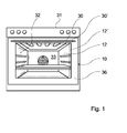
- Figure 1 shows an oven with a arranged in an oven housing 31 Oven muffle 32, which together with a oven door 10 according to the invention a Cooking space 33 limited.
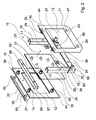
- the oven door 10 has a bar unit 11, a front part forming a front surface 12 and an inner surface forming an inner part 13 ( Figure 2).
- the last unit 11 comprises two side rails 34, 35 formed by U-profiles, which are located at the bottom of the Baking oven door 10 by means of a transverse bar 24 of the strip unit 11 are connected and in installed state with the oven door 10 closed run vertically.
- the crossbar 24 is bolted to the side rails 34, 35, but could also by another, the expert appears useful sense positive, positive and / or cohesive connections to the side rails 34, 35 may be connected.
- hinge units 26, 27 are arranged in the lower region, over which the oven door 10 is pivotally mounted.
- the front part 12 is from an outer visor formed on the front surface of a made of stainless steel aperture 36th glued flat ( Figure 1).
- the inner part 13 is formed by an inner visor.
- the front part 12 and the inner part 13 are made of glass, and basically also other, the expert would appear reasonable as conceivable materials, such as Plastic etc.
- Fastening means 14, 15, 16, 17, 18, 19, 20, 21 for producing a force and Form-fitting connections of four mounting units arranged.
- the fasteners 14, 15, 16, 17, 18, 19, 20, 21 are respectively in the corner regions of the front part 12 or of the inner part 13, in one of the panel 36 covered Border area.
- attachment means 14, 15, 16, 17 on the front part 12 and four fastening means 18, 19, 20, 21 on the inner part 13 can per corner area an advantageous Connection can be achieved, but it is also conceivable, more or less fasteners provided.
- the arranged in the upper region of the front part 12 fasteners 14, 15 are of identical receptacles formed, each through a recess of the front part 12 and extend through a respective recess of the diaphragm 36 and in the insertion direction 22nd over the front surface of the front part 12 and in the insertion direction 23 via an inner surface of the Front part 12 survive ( Figures 2, 5 and 6).
- the fastening means 14, 15 are here in each case via an integrally formed collar 37, 38 by means of an adhesive 43 on the inner surface of the front part 12 glued.
- the fastening means 14, 15 associated fastening means 18, 19 in the upper region of the inner part 13 of the oven door 10 are of identical pin formed, which extend in the direction of insertion 22 to the front part 12 and are in each case via an integrally formed collar 39, 40 by means of an adhesive 44 glued in the direction of the front part 12 facing surface of the inner part 13 ( Figures 2 and 7).
- the arranged in the lower region of the front part 12 fasteners 16, 17 are of identical pin formed, which extend in the direction of insertion 23 to the inner part 13 and are in each case via an integrally formed collar 41, 42 by means of an adhesive 45 the inside of the front part 12 glued ( Figures 2 and 4).
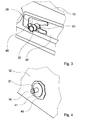
- the fasteners 16, 17 associated fastening means 20, 21 in the lower region of the inner part 13 of the Oven door 10 are formed by identical sockets, which are in the insertion direction 22nd extend to the front part 12, and are in each case via an integrally formed collar 46, 47 means an adhesive, not shown, in the direction of the front part 12 facing surface the inner part 13 glued ( Figures 2 and 3).
- the four mounting units are each one of a plug-in pin and formed by a socket fasteners 14, 15, 16, 17, 18, 19, 20, 21 are formed and are provided for the production of connectors, via which the front part 12 and the inner part 13 are directly coupled in the assembled state. Furthermore, the fastening units for tool-free assembly and disassembly provided by these are designed for the production of locking bonds.
- plug-in sockets trained fastening means 14, 15 in the upper region of the front part 12 in Longitudinal extension of over the inside of the front part 12 protruding part of two make each two opposite, passing through the sleeve wall recesses and formed as receptacles fastener 20, 21 in the Longitudinal at one point two opposite, passing through the sleeve wall Recesses on ( Figures 3 and 5).
- the fastening means 16, 17, 18, 19 designed as plug-in pins each have the Area of its free end a circumferential groove 51, 52 for correspondence with the spring clips 48, 49, 50 on.
- the locking pins 16, 17, 18, 19 are each tapered in the region of their free ends, in the of their fret 39, 40, 41, 42 remote plug-in direction 22, 23 is tapered.
- fasteners 16, 17, 18, 19 are also other, the skilled worker as meaningful appearing fasteners conceivable, such as threaded bolts, etc.
- the oven door 10 has a projecting beyond the front surface of the front part 12 Handle 30 ( Figures 1 and 2).
- Handle 30 On the handle 30 formed by a steel rod are two plug-in pins designed, identical fastening means 53, 54 welded, which are aligned perpendicular to the handle 30 and their shape as the Locking pin trained fasteners 16, 17, 18, 19 correspond.
- the handle 30 of the oven door 10 When mounting the oven door 10, the handle 30 of the oven door 10 is first in a holding device, not shown, with the fastening means 53, 54 perpendicular placed facing up. Subsequently, the front part 12, on the already the panel 36 is glued to the holding device with its front face down placed on and trained as sockets fasteners 14, 15 of the front part 12 on the locking pin formed as a fastening means 53, 54 of the handle 30 in Inserted plug-in direction 22, to the circumferential grooves 55 of the fastening means 53, 54th engage in the previously mounted on the fasteners 14,15 spring clip 50.
- the fastening means 53, 54 are conical, whereby these can be advantageously introduced into the fastening means 14, 15 and one on the other hand, the spring clip 50 when attaching the fastening means 14, 15 on the Fastening means 53, 54 advantageously spring-elastic, can be spread without tools.
- the fastening means 14, 15 thus serve at the same time for attachment of the handle 30th
- clamping means 28, 29 are of formed substantially U-shaped flat springs, in the assembled state, the last unit 11 and the inner part 13 with a perpendicular to the front surface or perpendicular to Inner surface of the inner part 13 acting clamping force in the hinge units 26, 27 tension free play.
- the fastening means 20, 21 thus form part of Clamping unit 25.
- the clamping means 28, 29 are on the fasteners 20, 21 the spring clip 48 mounted by placing these in the opposite recesses the fastening means 20, 21 are inserted laterally.
- the inner part 13 has at the bottom of beveled corner areas, in with the strip unit 11th clamped state parallel to the inner surface of the inner part 13 in a form-fitting manner with substantially triangular contact elements 63, 64 of the strip unit 11 come into contact, which are attached cohesively to the side strips 34, 35.
- elastic tensioning means on the last unit 11 engaged which are provided for generating further clamping forces.
- detent unit of the strip unit 11 is then from a side facing away from the inner part 13 an intermediate visor 62 engaged. It thus creates an inner part 13, the last unit 11 and the intermediate visor 62 comprehensive second assembly unit.
- the second mounting unit is then in Plug-in direction 22 led to the first mounting unit.
- the trained as a plug pin Fasteners 16, 17 thereby engage with their circumferential grooves 51 in the the fasteners 20, 21 fastened spring clip 48 and as plug-in pins trained fasteners 18, 19 thereby engage with their circumferential grooves 52 in the the fastening means 14, 15 fastened, front spring clip 49 a.
- the as plug-in pins trained fasteners 16, 17, 18, 19 may be due to their conical Training advantageous in the form of receptacles formed as fastening means 14, 15, 20, 21 and between the spring clips 48, 49 are inserted through the fastener 16, 17, 18, 19 are spring loaded without tools.
- front part 12 and the handle 30 may also be an alternative front part 12 ' and an alternative handle 30 'are mounted as shown in Fig. 1.
- the Front part 12 ' has with the front part 12 at least substantially identical fastening means and the handle 30 ', with the handle 30 at least substantially identical fastening means, so that the front part 12 'and the handle 30' with the remaining components of the oven door 10 are compatible.
Abstract
Description
Die Erfindung geht insbesondere aus von einer Haushaltsgerätetür nach dem Oberbegriff des Anspruchs 1.The invention is particularly based on a household appliance door according to the preamble of claim 1.
Aus der DE 100 33 358 C2 ist eine von einer Gargerätetür gebildete gattungsgemäße Haushaltsgerätetür mit einer Leisteneinheit bekannt. Die Haushaltsgerätetür weist ein von einer Außensichtscheibe gebildetes Frontteil auf, das eine Frontfläche bildet, und weist eine von einer Innensichtscheibe gebildetes Innenteil auf, das einen Innenfläche bildet. Die Außensichtscheibe ist auf die Leisteneinheit aufgeklebt, und die Innensichtscheibe ist über an der Leisteneinheit eingerastete Befestigungsmittel einer Befestigungseinheit an der Leisteneinheit gehalten.From DE 100 33 358 C2 a generic formed by a cooking appliance door Domestic appliance door with a bar unit known. The appliance door has a of an outer visor formed front part, which forms a front surface, and has an inner part formed by an inner panel, which forms an inner surface. The outer visor is glued to the last unit, and the inner visor is via fasteners of a fastening unit latched to the strip unit held the inguinal unit.
Die Aufgabe der Erfindung besteht insbesondere darin, eine gattungsgemäße Haushaltsgerätetür mit verbesserten Montageeigenschaften bereitzustellen. Die Aufgabe wird erfindungsgemäß durch die Merkmale des Patentanspruchs 1 gelöst, während vorteilhafte Ausgestaltungen und Weiterbildungen der Erfindung den Unteransprüchen und Nebenansprüchen entnommen werden können.The object of the invention is, in particular, a generic household appliance door to provide with improved mounting properties. The object is achieved according to the invention solved by the features of claim 1, while advantageous Refinements and developments of the invention the dependent claims and claims can be removed.
Die Erfindung geht insbesondere aus von einer Haushaltsgerätetür mit einer Leisteneinheit, einem eine Frontfläche bildenden Frontteil und einem eine Innenfläche bildenden Innenteil.The invention is particularly based on a household appliance door with a bar unit, a front part forming a front surface and an inner surface forming one Inner part.
Es wird vorgeschlagen, dass am Frontteil und/oder am Innenteil zumindest ein speziell ausgebildetes Befestigungsmittel zur Herstellung einer Kraft- und/oder Formschlussverbindung einer Befestigungseinheit angeordnet ist. Unter dem Begriff "angeordnet" soll in diesem Zusammenhang insbesondere kraftschlüssig, stoffschlüssig und/oder formschlüssig lösbar und vorteilhaft unlösbar befestigt, angeformt, eingegossen und/oder eingebracht verstanden werden. Dabei kann das Befestigungsmittel zumindest teilweise von einer Ausnehmung im Frontteil und/oder Innenteil oder vorteilhaft von einem körperlichen, insbesondere zusätzlichen Gegenstand gebildet sein. Mittels dem Begriff "speziell" soll in diesem Zusammenhang ausgedrückt werden, dass das Befestigungsmittel insbesondere nicht allein durch die Form des Frontteils und/oder des Innenteils, d.h. in Regel durch ein zumindest im Wesentlichen plattenförmiges Bauteil, an sich gegeben ist, sondern insbesondere von einer von einer ebenen Fläche abweichenden Ausgestaltung, wie insbesondere einer Ausnehmung und/oder einem über die Ebene überstehenden Fortsatzes. Unter einer "Leisteneinheit" soll in diesem Zusammenhang im Gegensatz zu einem einstückig geschlossenen Rahmen insbesondere eine Einheit verstanden werden, die aus zumindest zwei Bauteilen gebildet ist und/oder zumindest zu einer Seite zumindest teilweise offen ausgebildet ist.It is proposed that at the front part and / or on the inner part at least one special trained fastener for producing a force and / or positive connection a fastening unit is arranged. The term "arranged" is intended in In this context, in particular non-positively, materially and / or positively releasably and advantageously permanently attached, molded, cast and / or introduced be understood. In this case, the fastening means at least partially from a recess in the front part and / or inner part or advantageously of a physical, be formed in particular additional object. By the term "special" is meant in Expressed in this context, that the fastening means in particular not solely by the shape of the front part and / or the inner part, i. usually through at least substantially plate-shaped component, given in itself, but in particular from a deviating from a flat surface configuration, in particular a recess and / or a protruding over the plane extension. Under a "last unit" in this context, in contrast to a one piece closed framework, in particular a unit understood from at least two components is formed and / or at least partially open at least one side is trained.
Durch die Anordnung des speziell ausgebildeten Befestigungsmittels am Frontteil und/oder am Innenteil kann eine vorteilhaft einfache Montage und Demontage, beispielsweise zu Servicezwecken, derselben erreicht werden. Insbesondere kann vorteilhaft die Leisteneinheit unter Ausschluss einer direkten Klebeverbindung mit dem Frontteil und/oder mit dem Innenteil mit zumindest einem derselben gekoppelt werden, d.h. es kann vermieden werden, dass das Frontteil und/oder das Innenteil auf die Leisteneinheit geklebt werden muss. Ferner kann einfach ein vorteilhaftes Haushaltsgerätetürensystem mit wenigstens einer und vorzugsweise mehreren erfindungsgemäßen Haushaltsgerätetüren und zumindest einem Alternativbauteil erreicht werden, bei dem eine Montage mit geringem Aufwand auf verschiedene Alternativen umstellbar ist. Das Alternativbauteil kann dabei von verschiedenen, dem Fachmann als sinnvoll erscheinenden Bauteilen gebildet sein, wie beispielsweise von einem Handgriff, einer Blende usw., jedoch besonders vorteilhaft von einem Frontteil und/oder einem Innenteil, mittels dem einfach insbesondere wesentliche optische Umstellungen und Funktionsumstellungen realisiert werden können.Due to the arrangement of the specially trained fastener on the front part and / or on the inner part can advantageously a simple assembly and disassembly, for example for service purposes, the same can be achieved. In particular, the advantageous Strip unit excluding a direct adhesive connection with the front part and / or to be coupled to the inner part with at least one of them, i. it can be avoided that the front part and / or the inner part of the last unit must be glued. Furthermore, simply an advantageous home appliance door system with at least one and preferably a plurality of household appliance doors according to the invention and at least one alternative component can be achieved, in which an assembly with low effort on different alternatives can be switched. The alternative component can thereby be formed by various components that appear appropriate to the person skilled in the art be such as a handle, a bezel, etc., but especially advantageous of a front part and / or an inner part, by means of which simply in particular significant visual changes and function changes can be realized.
Das Frontteil und/oder das Innenteil kann von einer Blende, einem sonstigen Trägerteil und/oder besonders vorteilhaft von einer Sichtscheibe gebildet sein. Die Sichtscheibe kann vorteilhaft als Trägerbauteil eingebunden und weitere Trägerbauteile können zumindest schwächer und kostengünstiger dimensioniert und/oder auch eliminiert werden.The front part and / or the inner part of a panel, another carrier part and / or particularly advantageously formed by a viewing window. The lens can advantageously be integrated as a carrier component and further carrier components can at least be dimensioned weaker and cheaper and / or even eliminated.
In einer weiteren Ausgestaltung der Erfindung wird vorgeschlagen, dass zumindest zwei Sichtscheiben über die Befestigungseinheit direkt gekoppelt sind, wodurch mit wenigen, insbesondere konstruktiv einfach gestaltbaren und im Hinblick auf die Montage vorteilhaft auslegbaren Befestigungsmitteln eine Trägereinheit geschaffen werden kann. Unter "direkt gekoppelt" soll in diesem Zusammenhang insbesondere ein Ausschluss eines zwischen korrespondierenden Befestigungsmitteln angeordneten weiteren Trägermittels der Haushaltsgerätetür verstanden werden, wie insbesondere ein Ausschluss eines Leistenmittels der Leisteneinheit, was grundsätzlich jedoch auch denkbar wäre, beispielsweise indem ein an einem Frontteil und/oder Innenteil angeordnetes Befestigungsmittel mit einem an einem als Trägermittel dienenden Leistenmittel der Leisteneinheit befestigten Befestigungsmittel zur Herstellung einer Kraft- und/oder Formschlussverbindung koppelbar ist.In a further embodiment of the invention it is proposed that at least two Sight glasses are directly coupled via the fixing unit, whereby with few, in particular structurally simple to design and advantageous in terms of assembly extendable fasteners a carrier unit can be created. Under "direct coupled "is in this context, in particular an exclusion of between Corresponding fastening means arranged further support means of Domestic appliance door to be understood, in particular an exclusion of a groin the last unit, which in principle, however, would also be conceivable, for example in that arranged on a front part and / or inner part fastening means with a attached to a carrier means serving as a bar means of the bar unit fastening means for coupling a force and / or positive connection can be coupled is.
Vorzugsweise werden die zwei Sichtscheiben von einer Außen- und einer Innensichtscheibe gebildet, wodurch eine Trägereinheit geschaffen werden kann, mit der zumindest die Hauptbauteile der Haushaltsgerätetür, wie Leisteneinheit, Zwischensichtscheibe usw., vorteilhaft zusammengehalten und aufgrund einer erreichbaren relativ großen Erstreckung der Trägereinheit senkrecht zu den Sichtscheiben eine große Steifigkeit erzielt werden kann. Alternativ könnte jedoch auch eine Zwischensichtscheibe mit einer Außensichtscheibe und/oder mit einer Innensichtscheibe über ein entsprechendes Befestigungsmittel verbunden sein.Preferably, the two viewing panes of an outer and an inner panel formed, whereby a carrier unit can be created with the at least the main components of the household appliance door, such as last unit, intermediate visor, etc., advantageously held together and due to an achievable relatively large extension the support unit perpendicular to the lenses a great rigidity can be achieved can. Alternatively, however, could also be an intermediate visor with an outer visor and / or with an inner panel over a corresponding fastener be connected.
In einer weiteren Ausgestaltung der Erfindung wird vorgeschlagen, dass die Befestigungseinheit zur Herstellung einer Steckverbindung vorgesehen ist, wodurch zumindest einzelne Bauteile vorteilhaft geführt montiert werden können und eine hohe Prozesssicherheit erreichbar ist. Zur Herstellung der Steckverbindung können sämtliche, dem Fachmann als sinnvoll erscheinende Befestigungsmittel vorgesehen sein, wie beispielsweise zylindrische, runde und/oder eckige Steckmittel. Unter dem Begriff "vorgesehen" soll in diesem Zusammenhang insbesondere entsprechend ausgestattet und/oder ausgelegt verstanden werden. Weist die Befestigungseinheit jedoch zumindest ein sich in und/oder entgegen einer Steckrichtung verjüngendes Befestigungsmittel auf, indem dieses beispielsweise gestuft, konisch und/oder keilförmig ausgebildet ist, kann zum einen die Montage erleichtert und zum anderen kann einfach ungewünschtes Spiel, insbesondere zwischen korrespondierenden Befestigungsmitteln, zumindest reduziert werden.In a further embodiment of the invention, it is proposed that the fastening unit is provided for producing a plug connection, whereby at least individual components can be mounted advantageously guided and high process reliability is reachable. To produce the connector can all, the Professional be provided as meaningful attachment means, such as cylindrical, round and / or square plug-in means. By the term "intended" should in particular be appropriately equipped and / or designed in this context be understood. However, the fastening unit has at least one in and / or against a plug-in direction tapered fastening means by this For example, stepped, conical and / or wedge-shaped, can on the one hand facilitates the assembly and on the other hand can simply unwanted game, in particular between corresponding fasteners, at least reduced.
Durchgreift die Befestigungseinheit zumindest ein zwischen dem Frontteil und dem Innenteil angeordnetes Bauteil, kann erreicht werden, dass das Bauteil, wie beispielsweise ein Leistenmittel der Leisteneinheit und/oder ein Abdeckmittel, bei der Montage geführt exakt mittels der Befestigungseinheit positioniert und fixiert werden kann. Zudem kann erreicht werden, dass mittels einem Befestigungsmittel vorteilhaft mehrere Bauteile positioniert und/oder fixiert und zusätzliche Befestigungsmittel eingespart werden können.Passes through the attachment unit at least one between the front part and the inner part arranged component, can be achieved that the component, such as a Strip means of the strip unit and / or a covering, guided during assembly exactly can be positioned and fixed by means of the fastening unit. In addition, can be achieved be that positioned by means of a fastener advantageous several components and / or fixed and additional fasteners can be saved.
Ferner kann die Montage und/oder Demontage vereinfacht und kostengünstiger gestaltet werden, wenn die Befestigungseinheit zumindest weitgehend und besonders vorteilhaft vollständig zur werkzeuglosen Montage und/oder Demontage vorgesehen ist. Eine werkzeuglose Montage und/oder Demontage kann durch verschiedene Befestigungseinheiten erreicht werden, beispielsweise durch Befestigungseinheiten, die zur Handbedienung vorgesehene Schrauben und/oder Muttern oder vorgesehene Spannhebel usw. aufweisen.Furthermore, the assembly and / or disassembly can be simplified and made cheaper be when the fastening unit at least largely and particularly advantageous is completely designed for tool-free installation and / or disassembly. A tool-less Assembly and / or disassembly can be done by various mounting units be achieved, for example, by fastening units provided for manual operation Screws and / or nuts or provided clamping lever, etc. have.
Ist die Befestigungseinheit zur Herstellung einer Rastverbindung vorgesehen, kann zum einen die Montage weiter vereinfacht und zum anderen kann insbesondere eine zumindest weitgehend werkzeuglose Montage und/oder Demontage konstruktiv einfach erzielt werden.If the fastening unit is provided for producing a latching connection, can one further simplifies the assembly and on the other hand, in particular one can at least largely tool-free assembly and / or disassembly achieved structurally simple become.
Um ungewünschtes Spiel einfach beseitigen zu können, wird vorgeschlagen, dass die Haushaltsgerätetür mit einer Spanneinheit zur Erzeugung wenigstens einer zumindest im Wesentlichen senkrecht zur Frontfläche wirkenden Spannkraft ausgestattet ist. Dabei sind sämtliche, dem Fachmann als sinnvoll erscheinende Spanneinheiten denkbar, beispielsweise von Einlegeteilen gebildete Spanneinheiten, Schnellspannmechanismen mit Spannhebeln usw.In order to easily eliminate unwanted play, it is suggested that the Domestic appliance door with a clamping unit for generating at least one at least in Essentially perpendicular to the front surface acting clamping force is equipped. There are All conceivable to those skilled in clamping units conceivable, for example formed by inserts clamping units, quick release mechanisms with Clamping levers etc.
Ist dabei wenigstens eine Befestigungseinheit wenigstens teilweise einstückig mit der Spanneinheit ausgebildet, indem die Spanneinheit beispielsweise vorteilhaft direkt an einem Befestigungsmittel der Befestigungseinheit angreift und/oder ein Befestigungsmittel selbst von einem federelastischen Spannmittel gebildet ist, können zusätzliche Bauteile eingespart und der Montageaufwand und die Montagekosten können reduziert werden.Is at least one fastening unit at least partially integral with the Clamping unit formed by the clamping unit, for example, advantageously directly to a Fastening means of the fastening unit attacks and / or a fastening means itself formed by a spring-elastic clamping means, additional components saved and the assembly costs and installation costs can be reduced.
Zudem wird vorgeschlagen, dass im Bereich wenigstens einer Scharniereinheit zumindest ein Spannmittel der Spanneinheit angeordnet ist, wodurch insbesondere in hoch belasteten Bereichen gezielt ein Spiel zwischen gekoppelten Bauteilen vorteilhaft zumindest weitgehend vermieden werden kann. Dabei soll unter "im Bereich" der Scharniereinheit verstanden werden, dass das Spannmittel näher zu einer der Scharniereinheit zugeordneten Türecke angeordnet ist als einer dieser Türecke und der Scharniereinheit gegenüberliegenden Türecke.In addition, it is proposed that in the region of at least one hinge unit at least a tensioning means of the clamping unit is arranged, whereby in particular in highly loaded Areas targeted a game between coupled components advantageous at least can be largely avoided. It should under "in the area" of the hinge unit be understood that the tensioning means associated closer to one of the hinge unit Door corner is arranged as one of these door corner and the hinge unit opposite Door corner.
Ferner können Bauteile, Montageaufwand und Kosten eingespart werden, indem die Befestigungseinheit zumindest teilweise zur Befestigung eines Handgriffs vorgesehen ist.Furthermore, components, assembly costs and costs can be saved by the fastening unit is at least partially provided for attachment of a handle.
Die erfindungsgemäße Lösung kann bei verschiedenen, dem Fachmann als geeignet erscheinenden Haushaltsgerätetüren angewandt werden, jedoch besonders vorteilhaft bei Gargerätetüren, bei denen trotz der hohen Anforderungen bezüglich der Temperaturbeständigkeit mittels der erfindungsgemäßen Lösung eine besonders komfortable, einfache und schnelle Montage erreicht werden kann.The solution according to the invention can be used in various ways that appear suitable to the person skilled in the art Household appliance doors are applied, but particularly advantageous in Cooking device doors, which despite the high requirements in terms of temperature resistance by means of the solution according to the invention a particularly comfortable, simple and fast assembly can be achieved.
Weitere Vorteile ergeben sich aus der folgenden Zeichnungsbeschreibung. In der Zeichnung ist ein Ausführungsbeispiel der Erfindung dargestellt. Die Zeichnung, die Beschreibung und die Ansprüche enthalten zahlreiche Merkmale in Kombination. Der Fachmann wird die Merkmale zweckmäßigerweise auch einzeln betrachten und zu sinnvollen weiteren Kombinationen zusammenfassen.Further advantages emerge from the following description of the drawing. In the drawing an embodiment of the invention is shown. The drawing, the description and the claims include numerous features in combination. The expert The features will expediently consider individually and to meaningful further Combine combinations.
- Fig. 1Fig. 1
- einen Backofen von vorn mit einer erfindungsgemäßen Backofentür,an oven from the front with a oven door according to the invention,
- Fig. 2Fig. 2
- eine Explosionszeichnung der Backofentür,an exploded view of the oven door,
- Fig. 3Fig. 3
- einen vergrößerten Ausschnitt eines an einem unteren Bereich einer Innensichtscheibe der Backofentür angeordneten Befestigungsmittels,an enlarged detail of a at a lower portion of a Inner visor of the oven door arranged fastener,
- Fig. 4Fig. 4
- einen vergrößerten Ausschnitt eines an einem unteren Bereich einer Außensichtscheibe der Backofentür angeordneten Befestigungsmittels,an enlarged detail of a at a lower portion of a Outer visor of the oven door arranged fastener,
- Fig. 5Fig. 5
- einen vergrößerten Ausschnitt eines an einem oberen Bereich der Außensichtscheibe der Backofentür angeordneten Befestigungsmittels,an enlarged section of a at an upper portion of Outer visor of the oven door arranged fastener,
- Fig. 6Fig. 6
- eine Draufsicht auf die Außensichtscheibe der Backofentür im Bereich des Befestigungsmittels aus Fig. 5 ohne Federbügel und a plan view of the outer visor of the oven door in the area of the fastener of FIG. 5 without spring clip and
- Fig. 7Fig. 7
- einen vergrößerten Ausschnitt eines an einem oberen Bereich der Innensichtscheibe der Backofentür angeordneten Befestigungsmittels.an enlarged section of a at an upper portion of Interior visor of the oven door arranged fastener.
Figur 1 zeigt einen Backofen mit einer in einem Backofengehäuse 31 angeordneten
Backofenmuffel 32, die gemeinsam mit einer erfindungsgemäßen Backofentür 10 einen
Garraum 33 begrenzt.Figure 1 shows an oven with a arranged in an
Die Backofentür 10 weist eine Leisteneinheit 11, ein eine Frontfläche bildendes Frontteil
12 und ein eine Innenfläche bildendes Innenteil 13 auf (Figur 2). Die Leisteneinheit 11
umfasst zwei von U-Profilen gebildete Seitenleisten 34, 35, die im unteren Bereich der
Backofentür 10 mittels einer Querleiste 24 der Leisteneinheit 11 verbunden sind und im
eingebauten Zustand bei geschlossener Backofentür 10 senkrecht verlaufen. Die Querleiste
24 ist dabei mit den Seitenleisten 34, 35 verschraubt, könnte jedoch auch durch
eine andere, dem Fachmann als sinnvoll erscheinende kraftschlüssige, formschlüssige
und/oder stoffschlüssige Verbindungen mit den Seitenleisten 34, 35 verbunden sein. An
den Seitenleisten 34, 35 sind im unteren Bereich Scharniereinheiten 26, 27 angeordnet,
über die die Backofentür 10 schwenkbar gelagert ist. Das Frontteil 12 wird von einer Außensichtscheibe
gebildet, auf deren Frontfläche eine aus Edelstahl hergestellte Blende 36
flächig aufgeklebt ist (Figur 1). Das Innenteil 13 wird von einer Innensichtscheibe gebildet.
Das Frontteil 12 und das Innenteil 13 sind aus Glas hergestellt, wobei grundsätzlich auch
andere, dem Fachmann als sinnvoll erscheinende Materialien denkbar wären, wie beispielsweise
Kunststoff usw.The
Erfindungsgemäß sind unmittelbar am Frontteil 12 und am Innenteil 13 speziell ausgebildete
Befestigungsmittel 14, 15, 16, 17, 18, 19, 20, 21 zur Herstellung einer Kraft- und
Formschlussverbindungen von vier Befestigungseinheiten angeordnet. Die Befestigungsmittel
14, 15, 16, 17, 18, 19, 20, 21 sind jeweils in den Eckbereichen des Frontteils 12
bzw. des Innenteils 13 angeordnet, und zwar in einem von der Blende 36 überdeckten
Randbereich. Mit zumindest vier Befestigungsmitteln 14, 15, 16, 17 am Frontteil 12 und
vier Befestigungsmitteln 18, 19, 20, 21 am Innenteil 13 kann pro Eckbereich eine vorteilhafte
Verbindung erreicht werden, denkbar ist jedoch auch, mehr oder weniger Befestigungsmittel
vorzusehen. According to the invention directly on the
Die im oberen Bereich des Frontteils 12 angeordneten Befestigungsmittel 14, 15 sind von
baugleichen Steckhülsen gebildet, die sich jeweils durch eine Ausnehmung des Frontteils
12 und durch jeweils eine Ausnehmung der Blende 36 erstrecken und in Steckrichtung 22
über die Frontfläche des Frontteils 12 und in Steckrichtung 23 über ein Innenfläche des
Frontteils 12 überstehen (Figuren 2, 5 und 6). Die Befestigungsmittel 14, 15 sind dabei
jeweils über einen angeformten Bund 37, 38 mittels eines Klebstoffs 43 auf die Innenfläche
des Frontteils 12 aufgeklebt. Die den Befestigungsmitteln 14, 15 zugeordneten Befestigungsmittel
18, 19 im oberen Bereich des Innenteils 13 der Backofentür 10 sind von
baugleichen Steckbolzen gebildet, die sich in Steckrichtung 22 zum Frontteil 12 erstrecken
und sind jeweils über einen angeformten Bund 39, 40 mittels eines Klebstoffs 44 auf
eine in Richtung Frontteil 12 weisenden Fläche des Innenteils 13 geklebt (Figuren 2 und
7).The arranged in the upper region of the
Die im unteren Bereich des Frontteils 12 angeordneten Befestigungsmittel 16, 17 sind von
baugleichen Steckbolzen gebildet, die sich in Steckrichtung 23 zum Innenteil 13 erstrecken
und sind jeweils über einen angeformten Bund 41, 42 mittels eines Klebstoffs 45 auf
die Innenseite des Frontteils 12 geklebt (Figuren 2 und 4). Die den Befestigungsmitteln
16, 17 zugeordneten Befestigungsmittel 20, 21 im unteren Bereich des Innenteils 13 der
Backofentür 10 sind von baugleichen Steckhülsen gebildet, die sich in Steckrichtung 22
zum Frontteil 12 erstrecken, und sind jeweils über einen angeformten Bund 46, 47 mittels
eines nicht näher dargestellten Klebstoffs auf die in Richtung Frontteil 12 weisenden Fläche
des Innenteils 13 geklebt (Figuren 2 und 3).The arranged in the lower region of the
Die insgesamt vier Befestigungseinheiten werden jeweils von einem als Steckbolzen und
von einer Steckhülse ausgebildeten Befestigungsmittel 14, 15, 16, 17, 18, 19, 20, 21 gebildet
und sind zur Herstellung von Steckverbindungen vorgesehen, über die das Frontteil
12 und das Innenteil 13 im montierten Zustand direkt gekoppelt sind. Ferner sind die Befestigungseinheiten
zur werkzeuglosen Montage und Demontage vorgesehen, indem diese
zur Herstellung von Rastbindungen ausgebildet sind. Hierfür weisen die als Steckhülsen
ausgebildeten Befestigungsmittel 14, 15 im oberen Bereich des Frontteils 12 in
Längserstreckung des über die Innenseite des Frontteils 12 überstehenden Teils an zwei
Stellen jeweils zwei gegenüberliegende, durch die Hülsenwand hindurchtretende Ausnehmungen
und die als Steckhülsen ausgebildeten Befestigungsmittel 20, 21 in deren
Längsrichtung an einer Stelle zwei gegenüberliegende, durch die Hülsenwand hindurchtretende
Ausnehmungen auf (Figuren 3 und 5). Im Bereich der Ausnehmungen werden im
Wesentlichen U-förmige, aus einem Federdraht hergestellte Federbügel 48, 49, 50 auf die
Befestigungsmittel 14, 15, 20, 21 seitlich aufgeschoben, die durch die Ausnehmungen in
Innenräume der Befestigungsmittel 14, 15, 20, 21 greifen.The four mounting units are each one of a plug-in pin and
formed by a
Die als Steckbolzen ausgebildeten Befestigungsmittel 16, 17, 18, 19 weisen jeweils im
Bereich ihres freien Endes eine Umfangsnut 51, 52 zur Korrespondenz mit den Federbügeln
48, 49, 50 auf. Die als Steckbolzen ausgebildeten Befestigungsmittel 16, 17, 18, 19
sind jeweils im Bereich ihrer freien Enden konisch, in die von ihrem Bund 39, 40, 41, 42
abgewandte Steckrichtung 22, 23 sich verjüngend ausgebildet. Anstatt den dargestellten
Befestigungsmitteln 16, 17, 18, 19 sind jedoch auch andere, dem Fachmann als sinnvoll
erscheinende Befestigungsmittel denkbar, beispielsweise Gewindebolzen usw. Zusätzlich
zu den konischen Bereichen der Befestigungsmittel 16, 17, 18, 19 weisen die als Steckhülsen
ausgebildeten Befestigungsmittel 14, 15, 20, 21 jeweils an ihrem freien Ende einen
sich zum gegenüberliegenden Ende verjüngenden Aufnahmebereich auf, mittels dem eine
Kopplung der Befestigungsmittel 14, 15, 16, 17, 18, 19, 20, 21 weiter vereinfacht wird.The fastening means 16, 17, 18, 19 designed as plug-in pins each have the
Area of its free end a
Die Backofentür 10 weist einen über die Frontfläche des Frontteils 12 überstehenden
Handgriff 30 auf (Figuren 1 und 2). An dem von einer Stahlstange gebildeten Handgriff 30
sind zwei als Steckbolzen ausgebildete, baugleiche Befestigungsmittel 53, 54 angeschweißt,
die senkrecht zum Handgriff 30 ausgerichtet sind und von ihrer Form den als
Steckbolzen ausgebildeten Befestigungsmitteln 16, 17, 18, 19 entsprechen.The
Bei der Montage der Backofentür 10 wird zuerst der Handgriff 30 der Backofentür 10 in
eine nicht näher dargestellte Haltevorrichtung mit den Befestigungsmitteln 53, 54 senkrecht
nach oben weisend eingelegt. Anschließend wird das Frontteil 12, auf das bereits
die Blende 36 aufgeklebt ist, auf die Haltevorrichtung mit seiner Frontfläche nach unten
aufgelegt und die als Steckhülsen ausgebildeten Befestigungsmittel 14, 15 des Frontteils
12 auf die als Steckbolzen ausgebildeten Befestigungsmittel 53, 54 des Handgriffs 30 in
Steckrichtung 22 gesteckt, und zwar bis Umfangsnuten 55 der Befestigungsmittel 53, 54
in die bereits zuvor an den Befestigungsmitteln 14,15 montierten Federbügel 50 einrasten.
An ihren freien Enden sind die Befestigungsmittel 53, 54 konisch ausgebildet, wodurch
diese zum einen vorteilhaft in die Befestigungsmittel 14, 15 eingeführt werden können und
zum anderen die Federbügel 50 beim Aufstecken der Befestigungsmittel 14, 15 auf die
Befestigungsmittel 53, 54 vorteilhaft federelastisch, werkzeuglos gespreizt werden können.
Die Befestigungsmittel 14, 15 dienen damit gleichzeitig zur Befestigung des Handgriffs
30.When mounting the
Anschließend wird eine leistenförmige, parallel zum Handgriff 30 verlaufende Abdeckung
56 von der Innenseite des Frontteils 12 her mit Ausnehmungen 57, 58 auf die Befestigungsmittel
14, 15 aufgesteckt (Figur 2). Im montierten Zustand der Abdeckung 56 durchgreifen
die Befestigungsmittel 14, 15 die Ausnehmungen 57, 58 der Abdeckung 56 und
damit die Abdeckung 56 selbst. Es entsteht damit eine den Handgriff 30, das Frontteil 12
und die Abdeckung 56 umfassende erste Montageeinheit.Subsequently, a strip-shaped, parallel to the
In einem parallelen Montageplatz wird die Leisteneinheit 11 in Steckrichtung 23 mit Ausnehmungen
59, 60 der Querleiste 24 auf die Befestigungsmittel 20, 21 des Innenteils 13
aufgesteckt, die im montierten Zustand der Leisteneinheit 11 die Ausnehmungen 59, 60
und damit die Querleiste 24 durchgreifen. Nachdem die Befestigungsmittel 20, 21 durch
die Ausnehmungen 59, 60 geführt sind, werden in Umfangsnuten 61 der Befestigungsmittel
20, 21 Spannmittel 28, 29 einer Spanneinheit 25 seitlich aufgeschoben (Figur 3). Die
im Bereich der Scharniereinheiten 26, 27 angeordneten Spannmittel 28, 29 werden von
im Wesentlichen U-förmigen Plattfedern gebildet, die im montierten Zustand die Leisteneinheit
11 und das Innenteil 13 mit einer senkrecht zur Frontfläche bzw. senkrecht zur
Innenfläche des Innenteils 13 wirkenden Spannkraft im Bereich der Scharniereinheiten
26, 27 spielfrei verspannen. Die Befestigungsmittel 20, 21 bilden damit einen Teil der
Spanneinheit 25. Zusätzlich zu den Spannmitteln 28, 29 werden an den Befestigungsmitteln
20, 21 die Federbügel 48 montiert, indem diese in die gegenüberliegenden Ausnehmungen
der Befestigungsmittel 20, 21 seitlich eingeschoben werden. Das Innenteil 13
weist im unteren Bereich abgeschrägte Eckbereiche auf, die im mit der Leisteneinheit 11
verspannten Zustand parallel zur Innenfläche des Innenteils 13 formschlüssig mit im Wesentlichen
dreieckigen Anlageelementen 63, 64 der Leisteneinheit 11 in Anlage kommen,
die an den Seitenleisten 34, 35 stoffschlüssig befestigt sind. Zusätzlich zu der Spanneinheit
25 sind weitere, nicht näher dargestellte federelastische Spannmittel an der Leisteneinheit
11 eingerastet, die zur Erzeugung weiterer Spannkräfte vorgesehen sind.In a parallel mounting position, the
In eine nicht näher dargestellte Rasteinheit der Leisteneinheit 11 wird anschließend von
einer dem Innenteil 13 abgewandten Seite eine Zwischensichtscheibe 62 eingerastet. Es
entsteht damit eine das Innenteil 13, die Leisteneinheit 11 und die Zwischensichtscheibe
62 umfassende zweite Montageeinheit. Die zweite Montageeinheit wird anschließend in
Steckrichtung 22 zur ersten Montageeinheit geführt. Dabei werden die als Steckbolzen
ausgebildeten Befestigungsmittel 18, 19 des Innenteils 13 in die als Steckhülsen ausgebildeten
Befestigungsmittel 14, 15 des Frontteils 12 eingesteckt und die als Steckhülsen
ausgebildeten Befestigungsmittel 20, 21 des Innenteils 13 auf die als Steckbolzen ausgebildeten
Befestigungsmittel 16, 17 des Frontteils 12 aufgesteckt. Die als Steckbolzen ausgebildeten
Befestigungsmittel 16, 17 rasten dabei mit ihren Umfangsnuten 51 in die an
den Befestigungsmitteln 20, 21 befestigten Federbügel 48 ein und die als Steckbolzen
ausgebildeten Befestigungsmittel 18, 19 rasten dabei mit ihren Umfangsnuten 52 in die an
den Befestigungsmitteln 14, 15 befestigten, vorderen Federbügel 49 ein. Die als Steckbolzen
ausgebildeten Befestigungsmittel 16, 17, 18, 19 können aufgrund ihrer konischen
Ausbildung vorteilhaft in die als Steckhülsen ausgebildeten Befestigungsmittel 14, 15, 20,
21 und zwischen die Federbügel 48, 49 eingeführt werden, die durch die Befestigungsmittel
16, 17, 18, 19 werkzeuglos federelastisch gespreizt werden.In a not shown detent unit of the
Anstatt dem Frontteil 12 und dem Handgriff 30 können auch ein alternatives Frontteil 12'
und ein alternativer Handgriff 30' montiert werden, wie dies in Fig. 1 dargestellt ist. Das
Frontteil 12' weist dabei mit dem Frontteil 12 zumindest im Wesentlichen baugleiche Befestigungsmittel
und der Handgriff 30' weist mit dem Handgriff 30 zumindest im Wesentlichen
baugleiche Befestigungsmittel auf, so dass das Frontteil 12' und der Handgriff 30'
mit den restlichen Bauteilen der Backofentür 10 kompatibel sind. Instead of the
Bezugszeichen
- 10
- Gargerätetür
- 11
- Leisteneinheit
- 12
- Frontteil
- 13
- Innenteil
- 14
- Befestigungsmittel
- 15
- Befestigungsmittel
- 16
- Befestigungsmittel
- 17
- Befestigungsmittel
- 18
- Befestigungsmittel
- 19
- Befestigungsmittel
- 20
- Befestigungsmittel
- 21
- Befestigungsmittel
- 22
- Steckrichtung
- 23
- Steckrichtung
- 24
- Bauteil
- 25
- Spanneinheit
- 26
- Scharniereinheit
- 27
- Scharniereinheit
- 28
- Spannmittel
- 29
- Spannmittel
- 30
- Handgriff
- 31
- Backofengehäuse
- 32
- Backofenmuffel
- 33
- Garraum
- 34
- Seitenleiste
- 35
- Seitenleiste
- 36
- Blende
- 37
- Bund
- 38
- Bund
- 39
- Bund
- 40
- Bund
- 41
- Bund
- 42
- Bund
- 43
- Klebstoff
- 44
- Klebstoff
- 45
- Klebstoff
- 46
- Bund
- 47
- Bund
- 48
- Federbügel
- 49
- Federbügel
- 50
- Federbügel
- 51
- Umfangsnut
- 52
- Umfangsnut
- 53
- Befestigungsmittel
- 54
- Befestigungsmittel
- 55
- Umfangsnut
- 56
- Abdeckung
- 57
- Ausnehmung
- 58
- Ausnehmung
- 59
- Ausnehmung
- 60
- Ausnehmung
- 61
- Umfangsnut
- 62
- Zwischensichtscheibe
- 63
- Anlageelement
- 64
- Anlageelement
- 10
- cooking appliance
- 11
- strip unit
- 12
- front part
- 13
- inner part
- 14
- fastener
- 15
- fastener
- 16
- fastener
- 17
- fastener
- 18
- fastener
- 19
- fastener
- 20
- fastener
- 21
- fastener
- 22
- plug-in direction
- 23
- plug-in direction
- 24
- component
- 25
- clamping unit
- 26
- hinge unit
- 27
- hinge unit
- 28
- clamping means
- 29
- clamping means
- 30
- handle
- 31
- oven housing
- 32
- oven muffle
- 33
- oven
- 34
- sidebar
- 35
- sidebar
- 36
- cover
- 37
- Federation
- 38
- Federation
- 39
- Federation
- 40
- Federation
- 41
- Federation
- 42
- Federation
- 43
- adhesive
- 44
- adhesive
- 45
- adhesive
- 46
- Federation
- 47
- Federation
- 48
- spring clip
- 49
- spring clip
- 50
- spring clip
- 51
- circumferential groove
- 52
- circumferential groove
- 53
- fastener
- 54
- fastener
- 55
- circumferential groove
- 56
- cover
- 57
- recess
- 58
- recess
- 59
- recess
- 60
- recess
- 61
- circumferential groove
- 62
- From the glass
- 63
- contact element
- 64
- contact element
Claims (20)
Applications Claiming Priority (2)
| Application Number | Priority Date | Filing Date | Title |
|---|---|---|---|
| DE200410022967 DE102004022967A1 (en) | 2004-05-10 | 2004-05-10 | Household appliance door |
| DE102004022967 | 2004-05-10 |
Publications (2)
| Publication Number | Publication Date |
|---|---|
| EP1596135A2 true EP1596135A2 (en) | 2005-11-16 |
| EP1596135A3 EP1596135A3 (en) | 2008-07-30 |
Family
ID=34939763
Family Applications (1)
| Application Number | Title | Priority Date | Filing Date |
|---|---|---|---|
| EP05103870A Withdrawn EP1596135A3 (en) | 2004-05-10 | 2005-05-10 | Household appliance door |
Country Status (2)
| Country | Link |
|---|---|
| EP (1) | EP1596135A3 (en) |
| DE (1) | DE102004022967A1 (en) |
Cited By (2)
| Publication number | Priority date | Publication date | Assignee | Title |
|---|---|---|---|---|
| EP2546576A1 (en) * | 2011-07-13 | 2013-01-16 | BSH Bosch und Siemens Hausgeräte GmbH | Device for a domestic appliance |
| IT202000023188A1 (en) * | 2020-10-01 | 2022-04-01 | Smeg Spa | DOOR OF AN OVEN AND OVEN INCLUDING SAID DOOR |
Families Citing this family (2)
| Publication number | Priority date | Publication date | Assignee | Title |
|---|---|---|---|---|
| DE102007053563A1 (en) * | 2007-11-09 | 2009-05-14 | BSH Bosch und Siemens Hausgeräte GmbH | Hinge blind for door profile of e.g. baking-oven, door, has cover flange covering recess and exhibiting hinge bushing for pushing hinge, and side flange bent and attached in profile, where side flange is removable |
| DE102009011804B4 (en) * | 2009-03-05 | 2021-03-04 | BSH Hausgeräte GmbH | Household appliance, in particular an oven |
Citations (3)
| Publication number | Priority date | Publication date | Assignee | Title |
|---|---|---|---|---|
| DE7037721U (en) * | 1971-06-16 | Siemens Gmbh | Door to lock baking and roasting tubes | |
| FR2563612A3 (en) * | 1984-04-27 | 1985-10-31 | Licentia Gmbh | Door for cooking and roasting oven of a range |
| EP0735324A1 (en) * | 1995-03-24 | 1996-10-02 | Seb S.A. | Simplified oven door with removable module |
Family Cites Families (1)
| Publication number | Priority date | Publication date | Assignee | Title |
|---|---|---|---|---|
| DE10143925A1 (en) * | 2001-09-07 | 2003-04-17 | Bsh Bosch Siemens Hausgeraete | Cooking appliance, cooking appliance door and method for producing a door pane for the cooking appliance door |
-
2004
- 2004-05-10 DE DE200410022967 patent/DE102004022967A1/en not_active Withdrawn
-
2005
- 2005-05-10 EP EP05103870A patent/EP1596135A3/en not_active Withdrawn
Patent Citations (3)
| Publication number | Priority date | Publication date | Assignee | Title |
|---|---|---|---|---|
| DE7037721U (en) * | 1971-06-16 | Siemens Gmbh | Door to lock baking and roasting tubes | |
| FR2563612A3 (en) * | 1984-04-27 | 1985-10-31 | Licentia Gmbh | Door for cooking and roasting oven of a range |
| EP0735324A1 (en) * | 1995-03-24 | 1996-10-02 | Seb S.A. | Simplified oven door with removable module |
Cited By (3)
| Publication number | Priority date | Publication date | Assignee | Title |
|---|---|---|---|---|
| EP2546576A1 (en) * | 2011-07-13 | 2013-01-16 | BSH Bosch und Siemens Hausgeräte GmbH | Device for a domestic appliance |
| IT202000023188A1 (en) * | 2020-10-01 | 2022-04-01 | Smeg Spa | DOOR OF AN OVEN AND OVEN INCLUDING SAID DOOR |
| EP3978809A1 (en) * | 2020-10-01 | 2022-04-06 | SMEG S.p.A. | Door of an oven and oven comprising said door |
Also Published As
| Publication number | Publication date |
|---|---|
| DE102004022967A1 (en) | 2005-12-01 |
| EP1596135A3 (en) | 2008-07-30 |
Similar Documents
| Publication | Publication Date | Title |
|---|---|---|
| DE102006046908B4 (en) | wiper blade locking device | |
| DE4329956C2 (en) | Arrangement for holding a built-in hob | |
| DE102005037020A1 (en) | Household appliance door, has door carrier unit merged to mounting unit, where carrier unit includes beading units that are connected to hinge by plug and socket connection and fastening unit for form-fit connection with door front unit | |
| DE102014221784A1 (en) | Domestic appliance with an input device and a coding device | |
| DE102006029173A1 (en) | Fastening device for an attachment | |
| EP1596135A2 (en) | Household appliance door | |
| WO2012079851A1 (en) | Wiper device | |
| DE2735627A1 (en) | WIPING DEVICE FOR WINDOWS OF MOTOR VEHICLES | |
| DE19923487B4 (en) | Abutment with molding for attaching control cables | |
| DE10143920A1 (en) | Cooking appliance door has intermediate panel supported between front and inner door panels via panel holder | |
| DE202011051645U1 (en) | Furniture floor with lamp unit | |
| DE2742021A1 (en) | WIPING DEVICE FOR WINDOWS OF MOTOR VEHICLES | |
| DE102011056804B4 (en) | Component for installation in an interior of a motor vehicle | |
| DE102019103964B3 (en) | Holding device | |
| EP1243473A2 (en) | Transport container device for installation in a motor vehicle for example a device with a loading opening | |
| DE102008031246A1 (en) | Appliances diaphragm device | |
| DE102010019383A1 (en) | Electronic device e.g. impedance converter, for attachment at vehicle body, has fasteners designed as screw, holder cooperating with screw, and housing with stopper defining range of motion of holder during actuation of screw | |
| EP2420607B1 (en) | Faceplate of an operating unit for a domestic appliance, operating unit for a domestic appliance and domestic appliance | |
| EP3213019A1 (en) | Household appliance with an input device, which comprises a flexible film | |
| DE102008030786A1 (en) | Ausfachungsrahmen for building facades | |
| EP1479978B1 (en) | Panel holder | |
| DE10137842B4 (en) | Component for mounting in a body part, in particular light | |
| EP3543452A1 (en) | Door seal with a fixing element | |
| DE102004052045A1 (en) | Device for household appliance door e.g. equipment door has grasping unit with one frame unit and coupler unit, by means of which frame unit is connected with connection unit whereby coupler unit is integrated with channel unit | |
| DE102010009270A1 (en) | Detent arrangement for locking components e.g. inner diaphragms, of headlight in motor car, has pulling element arranged at component to introduce tensile forces such that engagement hooks are locked into aperture in another component |
Legal Events
| Date | Code | Title | Description |
|---|---|---|---|
| PUAI | Public reference made under article 153(3) epc to a published international application that has entered the european phase |
Free format text: ORIGINAL CODE: 0009012 |
|
| AK | Designated contracting states |
Kind code of ref document: A2 Designated state(s): AT BE BG CH CY CZ DE DK EE ES FI FR GB GR HU IE IS IT LI LT LU MC NL PL PT RO SE SI SK TR |
|
| AX | Request for extension of the european patent |
Extension state: AL BA HR LV MK YU |
|
| PUAL | Search report despatched |
Free format text: ORIGINAL CODE: 0009013 |
|
| AK | Designated contracting states |
Kind code of ref document: A3 Designated state(s): AT BE BG CH CY CZ DE DK EE ES FI FR GB GR HU IE IS IT LI LT LU MC NL PL PT RO SE SI SK TR |
|
| AX | Request for extension of the european patent |
Extension state: AL BA HR LV MK YU |
|
| 17P | Request for examination filed |
Effective date: 20090130 |
|
| AKX | Designation fees paid |
Designated state(s): AT BE BG CH CY CZ DE DK EE ES FI FR GB GR HU IE IS IT LI LT LU MC NL PL PT RO SE SI SK TR |
|
| 17Q | First examination report despatched |
Effective date: 20141016 |
|
| RAP1 | Party data changed (applicant data changed or rights of an application transferred) |
Owner name: BSH HAUSGERAETE GMBH |
|
| STAA | Information on the status of an ep patent application or granted ep patent |
Free format text: STATUS: THE APPLICATION IS DEEMED TO BE WITHDRAWN |
|
| 18D | Application deemed to be withdrawn |
Effective date: 20141202 |