EP1596110B1 - Mischventil für Wasser - Google Patents
Mischventil für Wasser Download PDFInfo
- Publication number
- EP1596110B1 EP1596110B1 EP20050011903 EP05011903A EP1596110B1 EP 1596110 B1 EP1596110 B1 EP 1596110B1 EP 20050011903 EP20050011903 EP 20050011903 EP 05011903 A EP05011903 A EP 05011903A EP 1596110 B1 EP1596110 B1 EP 1596110B1
- Authority
- EP
- European Patent Office
- Prior art keywords
- water
- control member
- shaft
- zero position
- housing
- Prior art date
- Legal status (The legal status is an assumption and is not a legal conclusion. Google has not performed a legal analysis and makes no representation as to the accuracy of the status listed.)
- Expired - Lifetime
Links
Images


Classifications
-
- F—MECHANICAL ENGINEERING; LIGHTING; HEATING; WEAPONS; BLASTING
- F16—ENGINEERING ELEMENTS AND UNITS; GENERAL MEASURES FOR PRODUCING AND MAINTAINING EFFECTIVE FUNCTIONING OF MACHINES OR INSTALLATIONS; THERMAL INSULATION IN GENERAL
- F16K—VALVES; TAPS; COCKS; ACTUATING-FLOATS; DEVICES FOR VENTING OR AERATING
- F16K27/00—Construction of housing; Use of materials therefor
- F16K27/04—Construction of housing; Use of materials therefor of sliding valves
- F16K27/044—Construction of housing; Use of materials therefor of sliding valves slide valves with flat obturating members
- F16K27/045—Construction of housing; Use of materials therefor of sliding valves slide valves with flat obturating members with pivotal obturating members
-
- F—MECHANICAL ENGINEERING; LIGHTING; HEATING; WEAPONS; BLASTING
- F16—ENGINEERING ELEMENTS AND UNITS; GENERAL MEASURES FOR PRODUCING AND MAINTAINING EFFECTIVE FUNCTIONING OF MACHINES OR INSTALLATIONS; THERMAL INSULATION IN GENERAL
- F16K—VALVES; TAPS; COCKS; ACTUATING-FLOATS; DEVICES FOR VENTING OR AERATING
- F16K11/00—Multiple-way valves, e.g. mixing valves; Pipe fittings incorporating such valves
- F16K11/02—Multiple-way valves, e.g. mixing valves; Pipe fittings incorporating such valves with all movable sealing faces moving as one unit
- F16K11/06—Multiple-way valves, e.g. mixing valves; Pipe fittings incorporating such valves with all movable sealing faces moving as one unit comprising only sliding valves, i.e. sliding closure elements
- F16K11/072—Multiple-way valves, e.g. mixing valves; Pipe fittings incorporating such valves with all movable sealing faces moving as one unit comprising only sliding valves, i.e. sliding closure elements with pivoted closure members
- F16K11/074—Multiple-way valves, e.g. mixing valves; Pipe fittings incorporating such valves with all movable sealing faces moving as one unit comprising only sliding valves, i.e. sliding closure elements with pivoted closure members with flat sealing faces
-
- F—MECHANICAL ENGINEERING; LIGHTING; HEATING; WEAPONS; BLASTING
- F16—ENGINEERING ELEMENTS AND UNITS; GENERAL MEASURES FOR PRODUCING AND MAINTAINING EFFECTIVE FUNCTIONING OF MACHINES OR INSTALLATIONS; THERMAL INSULATION IN GENERAL
- F16K—VALVES; TAPS; COCKS; ACTUATING-FLOATS; DEVICES FOR VENTING OR AERATING
- F16K11/00—Multiple-way valves, e.g. mixing valves; Pipe fittings incorporating such valves
- F16K11/02—Multiple-way valves, e.g. mixing valves; Pipe fittings incorporating such valves with all movable sealing faces moving as one unit
- F16K11/06—Multiple-way valves, e.g. mixing valves; Pipe fittings incorporating such valves with all movable sealing faces moving as one unit comprising only sliding valves, i.e. sliding closure elements
- F16K11/072—Multiple-way valves, e.g. mixing valves; Pipe fittings incorporating such valves with all movable sealing faces moving as one unit comprising only sliding valves, i.e. sliding closure elements with pivoted closure members
- F16K11/076—Multiple-way valves, e.g. mixing valves; Pipe fittings incorporating such valves with all movable sealing faces moving as one unit comprising only sliding valves, i.e. sliding closure elements with pivoted closure members with sealing faces shaped as surfaces of solids of revolution
-
- F—MECHANICAL ENGINEERING; LIGHTING; HEATING; WEAPONS; BLASTING
- F16—ENGINEERING ELEMENTS AND UNITS; GENERAL MEASURES FOR PRODUCING AND MAINTAINING EFFECTIVE FUNCTIONING OF MACHINES OR INSTALLATIONS; THERMAL INSULATION IN GENERAL
- F16K—VALVES; TAPS; COCKS; ACTUATING-FLOATS; DEVICES FOR VENTING OR AERATING
- F16K11/00—Multiple-way valves, e.g. mixing valves; Pipe fittings incorporating such valves
- F16K11/10—Multiple-way valves, e.g. mixing valves; Pipe fittings incorporating such valves with two or more closure members not moving as a unit
- F16K11/14—Multiple-way valves, e.g. mixing valves; Pipe fittings incorporating such valves with two or more closure members not moving as a unit operated by one actuating member, e.g. a handle
- F16K11/16—Multiple-way valves, e.g. mixing valves; Pipe fittings incorporating such valves with two or more closure members not moving as a unit operated by one actuating member, e.g. a handle which only slides, or only turns, or only swings in one plane
- F16K11/163—Multiple-way valves, e.g. mixing valves; Pipe fittings incorporating such valves with two or more closure members not moving as a unit operated by one actuating member, e.g. a handle which only slides, or only turns, or only swings in one plane only turns
- F16K11/165—Multiple-way valves, e.g. mixing valves; Pipe fittings incorporating such valves with two or more closure members not moving as a unit operated by one actuating member, e.g. a handle which only slides, or only turns, or only swings in one plane only turns with the rotating spindles parallel to the closure members
-
- F—MECHANICAL ENGINEERING; LIGHTING; HEATING; WEAPONS; BLASTING
- F16—ENGINEERING ELEMENTS AND UNITS; GENERAL MEASURES FOR PRODUCING AND MAINTAINING EFFECTIVE FUNCTIONING OF MACHINES OR INSTALLATIONS; THERMAL INSULATION IN GENERAL
- F16K—VALVES; TAPS; COCKS; ACTUATING-FLOATS; DEVICES FOR VENTING OR AERATING
- F16K27/00—Construction of housing; Use of materials therefor
- F16K27/02—Construction of housing; Use of materials therefor of lift valves
- F16K27/0263—Construction of housing; Use of materials therefor of lift valves multiple way valves
-
- F—MECHANICAL ENGINEERING; LIGHTING; HEATING; WEAPONS; BLASTING
- F16—ENGINEERING ELEMENTS AND UNITS; GENERAL MEASURES FOR PRODUCING AND MAINTAINING EFFECTIVE FUNCTIONING OF MACHINES OR INSTALLATIONS; THERMAL INSULATION IN GENERAL
- F16K—VALVES; TAPS; COCKS; ACTUATING-FLOATS; DEVICES FOR VENTING OR AERATING
- F16K31/00—Actuating devices; Operating means; Releasing devices
- F16K31/02—Actuating devices; Operating means; Releasing devices electric; magnetic
- F16K31/04—Actuating devices; Operating means; Releasing devices electric; magnetic using a motor
- F16K31/05—Actuating devices; Operating means; Releasing devices electric; magnetic using a motor specially adapted for operating hand-operated valves or for combined motor and hand operation
- F16K31/055—Actuating devices; Operating means; Releasing devices electric; magnetic using a motor specially adapted for operating hand-operated valves or for combined motor and hand operation for rotating valves
-
- F—MECHANICAL ENGINEERING; LIGHTING; HEATING; WEAPONS; BLASTING
- F16—ENGINEERING ELEMENTS AND UNITS; GENERAL MEASURES FOR PRODUCING AND MAINTAINING EFFECTIVE FUNCTIONING OF MACHINES OR INSTALLATIONS; THERMAL INSULATION IN GENERAL
- F16K—VALVES; TAPS; COCKS; ACTUATING-FLOATS; DEVICES FOR VENTING OR AERATING
- F16K37/00—Special means in or on valves or other cut-off apparatus for indicating or recording operation thereof, or for enabling an alarm to be given
- F16K37/0075—For recording or indicating the functioning of a valve in combination with test equipment
- F16K37/0083—For recording or indicating the functioning of a valve in combination with test equipment by measuring valve parameters
-
- F—MECHANICAL ENGINEERING; LIGHTING; HEATING; WEAPONS; BLASTING
- F16—ENGINEERING ELEMENTS AND UNITS; GENERAL MEASURES FOR PRODUCING AND MAINTAINING EFFECTIVE FUNCTIONING OF MACHINES OR INSTALLATIONS; THERMAL INSULATION IN GENERAL
- F16K—VALVES; TAPS; COCKS; ACTUATING-FLOATS; DEVICES FOR VENTING OR AERATING
- F16K37/00—Special means in or on valves or other cut-off apparatus for indicating or recording operation thereof, or for enabling an alarm to be given
- F16K37/0075—For recording or indicating the functioning of a valve in combination with test equipment
- F16K37/0091—For recording or indicating the functioning of a valve in combination with test equipment by measuring fluid parameters
-
- Y—GENERAL TAGGING OF NEW TECHNOLOGICAL DEVELOPMENTS; GENERAL TAGGING OF CROSS-SECTIONAL TECHNOLOGIES SPANNING OVER SEVERAL SECTIONS OF THE IPC; TECHNICAL SUBJECTS COVERED BY FORMER USPC CROSS-REFERENCE ART COLLECTIONS [XRACs] AND DIGESTS
- Y10—TECHNICAL SUBJECTS COVERED BY FORMER USPC
- Y10T—TECHNICAL SUBJECTS COVERED BY FORMER US CLASSIFICATION
- Y10T137/00—Fluid handling
- Y10T137/8593—Systems
- Y10T137/86493—Multi-way valve unit
- Y10T137/86815—Multiple inlet with single outlet
- Y10T137/86823—Rotary valve
Definitions
- the present invention relates to a water mixing valve and, more particularly, to a water mixing valve having two water inlets, for instance for receiving respectively hot and cold water, and a mixing chamber for mixing flows from the two water inlets.
- US 5,487,408 describes a water sink system, comprising a water discharge member, two rotatable knobs for allowing hot water and cold water to flow into the water discharge member and meet there to produce discharged water with a desired temperature, a scale provided near each of the turnable knobs and having a plurality of graduation marks, and a pointer provided on each of the turnable knobs and turnable with the latter, so that when a user by turning the turnable knobs reaches a desired temperature, each pointer points to a respective graduation mark of each scale, with graduation marks can be memorised by a user and thereafter he can turn the knobs immediately to the memorized graduation marks.
- US 5,826,617 describes a water sink system comprising two knobs each tunable to adjust hot water and cold water correspondingly, and means for turning knobs to a predetermined angle so that a water from a mixing device connected with both the knobs flows with a desired temperature, the means including a scale formed as a disc and provided with a plurality of lines with members, and a central opening so as to be placed on an outer surface of a sink, and a pointer arranged in a bushing extending through the central opening of the scale and located inside a handle, so that by turning of the handle the pointer is turned relative to the scale.
- DE 31 20 171 A1 upon which the precharacterising portion of appended claim 1 is based, describes a manually operable water mixer tap having a rotatable control handle which rotates relative to markings provided on the outer housing of the valve such that a user can position the handle relative to the markings.
- the rotatable control member is freely rotatable continuously in one direction, it is difficult to ensure that it is correctly positioned. This is particularly important when the valve is used for controlling hot and cold water in a shower. In particular, it is very important that the shower can easily and effectively be returned to the off position and, when turned on, advanced first into the cold water supply.
- a water mixing valve having:
- control assembly may be moved until the zero position is detected. At that point, the position of the control assembly is known. Hence, subsequent positions for the control assembly may be determined according to the amount by which it is moved.
- control assembly includes a control member having said openings and a shaft extending axially from the control member, the control assembly being rotatable by the shaft and the zero position indicator being provided at a predetermined position around the periphery of the shaft remote from the control member.
- the position of the control member may be detected remotely.
- the zero position indicator extends axially along the shaft such that it can be detected at various positions along the shaft.
- the zero position detector need not be located accurately with respect to the length of the shaft.
- control member and shaft are supported in the housing, the housing defining a drive aperture through which the shaft extends so as to be rotatable from outside the housing wherein the zero position indicator is positioned outside the housing.
- the zero position detector may be easily accessible.
- the housing includes an outer surface around the shaft and the zero position detector is mounted on the outer surface adjacent the shaft.
- a plurality of detector mounts may be provided on the outer surface around the shaft, each detector mount being for receiving the zero position detector.
- the zero position detector may be located in one of a plurality of positions around the shaft. This enables the zero position for the control assembly relative to the water inlets to be varied according to the requirements of the user.
- two detector mounts are provided, one diametrically opposed to the other with regard to the shaft.
- the position at which the zero position detector is mounted may be determined according to how the water inlets are connected to the water supplies.
- the water inlet is normally connected to a hot water supply and that a particular detector mount is used for the zero position detector.
- the zero position detector may easily be moved to the other detector mount such that the device will operate as normal.
- zero position detectors may be provided at more than one of the detector mounts with an associated control system responding only to the appropriate zero position detector.
- the zero position indicator may be a cam such as a recess or a protrusion and the zero position detector may comprise a micro switch.
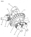
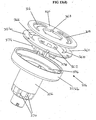
- a water mixing valve having a first inlet 2, a second inlet 4 and an outlet 6.
- the water mixing valve includes a housing made up of a first half 8 and a second half 10 which together define a mixing chamber 12.
- a mixing chamber 12 the mixing chamber 12
- the inlets 2, 4 and outlet 6 are provided respectively with pipes 2a, 4a, and 6a attached by screw caps 2b, 4b, and 6b.
- filters 2c and 4c are housed in the inlets and a baffle 400, to be described below, is housed in the outlet.
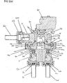
- a control member 14 is provided adjacent the ends of the water inlets 2,4, thereby separating the water inlets 2,4 from the mixing chamber 12.
- control member 14 is a plate having first and second tapered openings 16,18.
- the water inlets 2,4 seal against a first surface 20 of the control member 14.
- the control member 14 may then be rotated so as to bring the opening 16,18 in line with the water inlets 2,4 and control the proportion of water entering the mixing chamber 12.
- a second surface 22 of the control member 14 faces the mixing chamber 12.
- a support 24 abuts the second surface 22 of the control member 14.
- Formed integrally with the support 24 is a shaft 26 by which the support 24 and control member 14 may be rotated.
- the shaft 26 extends through a drive aperture 27 in the housing.
- a motor 28 such as a stepper motor, and gearbox is provided to rotate the shaft 26 and, hence, the control member 14.
- the shaft 26 could be rotatable via a manual mechanism.
- a temperature sensor 30 is located in the mixed flow of water and, when the water inlets 2 and 4 are used respectively for hot and cold water, the information derived from the temperature sensor 30 can be used to control the motor 28 and, hence, the position of the control member 14 and the temperature of the mixed flow of outlet water.
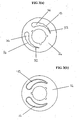
- Figures 3(a) and (b) illustrate two different control members 14 for use in the valve.
- Figure 3(a) illustrates a control member 14 having tapered openings 16 and 18 which are stepped with generally parallel sides.
- the control member 14 of Figure 3(b) has tapered openings which taper continuously from their widest ends to their narrowest ends.
- the present application recognises for the first time that using a control member such as that illustrated in Figure 3(b) with standard water inlets results in a non-linear change in flow with respect to rotation of the control member.
- water flow from a water inlet is determined by the open area presented to it by a corresponding tapered opening in the control member.
- movement of the tapered opening relative to the water inlet will not result in a linear change in open area.
- Incremental movements as an inlet first moves over the an opening cause large changes in flow due to the back pressure and proportionally large increases in available cross-sectional area for flow.
- movements of the inlet over the wider end of the opening have less effect with regard to back pressure and cause proportionally less change with regard to open cross-sectional area.
- the intervals between steps corresponds to the extent of the water inlet in the direction of movement of the control member.
- the open area presented to the water inlet (and through which water may flow into the mixing chamber 12) increases linearly with movement.
- a step is provided in the opening 16.
- the total step is provided symmetrically on the opening 16 by virtue of two steps 32a and 32b.
- the total step provided by the steps 32a and 32b has a width equal to the narrowest section 32 of the opening 16.
- the next section 34 in the opening 16 then again has generally parallel sides. In this way, as the water inlet moves from position B to position C, the open area presented to the water inlet again increases linearly and, furthermore, increases linearly at the same rate as the narrowest section 32.
- the opening 16 includes a series of pairs of symmetric steps, each pair having a width equal to the width of the narrowest section 32. In this way, from the narrowest section 32 to the widest section 36, movement of the opening 16 relative to the water inlet provides a linearly increasing open area and, hence, linearly increasing flow.
- the water inlets are circular, it is possible to provide a circular section 38 as part of the widest section 36. In this way, full opening of the water inlet can be achieved so as to ensure maximum flow.
- the control member 14 of Figure 3(b) can be used together with inserts in the water inlets 2 and 4.
- a suitable insert 40 is illustrated in Figures 5(a) and (b).
- the insert may be fitted in the valve as illustrated in Figure 6.
- the inserts 40 substantially fill the cross-section of the inlets and are provided with a slot-like opening 42.
- the inserts 40 are positioned in the inlets 2 and 4 so as to present their slotted openings 42 adjacent the tapered openings 16,18 of the control member 14.
- the slotted openings 42 are orientated perpendicular to the direction of movement of the tapered openings 16,18.
- the slotted openings 42 are orientated in a radial direction relative to the valve and control member 14.
- the increase in open cross-sectional area into the mixing chamber 12 is approximately proportional to the width of the tapered openings 16,18 presented to the water inlet.
- mixing of the water from the water inlets 2,4 is approximately proportional to movement of the valve and control member 14.
- slotted openings are particularly advantageous for systems having large differences in pressure between the two inlets. For instance, when used with combi heaters, cold to hot water pressure can have a ratio as much as 33 : 1.
- the openings 16,18 are positioned relative to one another accordingly.
- the water inlets 2,4 are diametrically opposed across the axis of rotation of the control member 14. This enables the control member 14 to operate symmetrically in either direction.
- control member 14 Upon rotation of the control member 14, the following operation is preferred.
- the control member 14 is rotated clockwise as illustrated in Figure 3 such that the first inlet 2 is exposed to the widest section 36 of the opening 16.
- the second inlet 4 is still closed by the control member 14.
- the narrowest section 32 of the second opening 18 moves across the second inlet 4 and progressively increases the flow from this inlet by the same amount.
- the second inlet 4 reaches the widest section 36 of the second opening 18 to allow maximum flow from the second inlet 4, whilst the first inlet 2 is closed by the control member 14.
- further rotation of the control member 14 will then open the second inlet 4 with the first opening 16.
- anti-clockwise rotation of the control member 14 will have a similar effect.
- the control member 14 will be rotated through the full-cold position then through the mixing positions with progressively more hot water until a desired temperature is achieved.
- the mixer valve provides an unnecessary amount of cold water to the outlet during start-up.
- the control member will move directly from the off position to a mixing position.
- the narrowest sections are preferably spaced apart by approximately 3 times the size of the inlets.
- a suitable control member is illustrated in Figure 7.
- control member 14 can be rotated from the off position in an opposite direction so as to make use of the maximum flow position of the other tapered opening 16,18.
- the openings can, of course, be applied to other types of control member.
- the openings can be arranged in a plate for linear motion.
- they can be located in a cylindrical control member.
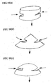
- FIGS 10(a), (b) and (c) illustrate various forms of non-planar control members which at least partly enclose the mixing chamber.
- the particular illustrated examples are respectively cylindrical, conical and hemispherical. These arrangements are particularly advantageous since the water inlet flows are naturally at least partly opposed. Hence, water inlet flows passing through the openings of the control member will naturally mix with one another before leaving the mixing chamber without any special features for creating mixing within the chamber.
- FIG 11 illustrates the sealing components at the ends of each of the water inlets 2,4.
- a cup seal 50 is provided internally with a coil spring 51.
- the cup seal 50 seals with the inner periphery of an inlet 2,4 and is sprung forwardly by the coil spring 51 so as to maintain a seal with the control member 14.
- the cup seals 50 must effectively seal with the control member 14. Furthermore, they may remain in this position for a considerable amount of time. In view of this, the springs provide a strong sealing pressure between the cup seals 50 and the control member 14.
- the cup seals 50 seal directly onto the moving control member 14.
- Using cup seals with a large inwardly extending sealing surface achieves good sealing, but there is significant friction between the sealing surface and the control member 14. This can cause resistance to rotation of the control member 14 and also induces wear in the cup seal.
- inlet pressures can vary considerably depending on the particular installation. Mains water supply in the U.K. can reach 16 bar though is supplied to houses with 12 bar pipe. However, in practice, in a domestic installation, pressure might vary from 0.1 bar to 10 bar, some boiler manufactures specifying that all fittings must be specified to 10 bar.
- the cup seal 50 preferably provides a good sealing force for a variety of different pressures, but without creating undue frictional forces with the control member 14.
- Figure 12 illustrates a cup seal 150 which includes an annular protrusion 152 extending from what would have otherwise been the inwardly extending sealing surface 154.
- the annular protrusion 152 thus forms the main seal with the control member 14.
- the inwardly extending sealing surface 154 will also provide some sealing effect together with the annular protrusion 152.
- a space 156 is formed under the inwardly extending portion 154.
- This space 156 helps to accommodate variations in water pressure and reduce frictional drag between the cup seal 150 and the control member 14.
- water is able to feed into the space 156 under the inwardly extending portion 154.
- the force between the cup seal 150, in particular the annular protrusion 152, and the control member 14 does not increase as much. This assists in providing a constant sealing force between the cup seal 150 and the control member 14.
- the sealing force may thus be kept towards its minimum so as to minimize the drag between the cup seals 150 and the control member 14.
- the cup seals 50,150 may additionally be coated with a low friction material such as PTFE.
- the inlets 2 and 4 seal directly with the control member 14. This is advantageous, since it requires a reduced number of parts and is of a simple construction. However, as mentioned above, there are problems in providing a good seal between the inlets 2,4 and the control member without producing undue drag and wear between seals of the inlets 2,4 and the control member 14.
- control member 14 is constructed from steel coated with a friction reducing material such as PTFE on its first surface 20. This allows the use of a good sealing pressure even with conventional cup seals 50.
- Figures 13(a) and (b) illustrate the support structure 24 and shaft 26, together with the control member 14. They also illustrate a mixing feature 200 to be described below.
- the support structure 24 includes a base wall 24a and a peripheral wall 24b.
- the control member 14 is supported at its outer periphery by the top surface 24c of the peripheral wall 24b. In this way, the mixing chamber 12 is formed within the support structure 24 and the control member 14.
- protrusions 62 are provided on the top surface 24c of the peripheral wall 24b. These protrusions 62 engage in recesses 63 around the outer periphery of the control member 14 so that the control member 14 may be pressed against the support structure 24 and fixed rotationally.
- shaft 26 takes the form of a hollow cylinder having a plurality of outlet openings 70 at its end furthermost from the control member 14. It extends from the outer surface of the base wall 24a, surrounding a central aperture 24d in the base wall 24a.
- water flows through the tapered openings 16 and 18 into the mixing chamber 12 defined by the support structure 24 and control member 14.
- the mixed water then passes through the hollow shaft 26 and out of the outlet openings 70 into the outlet chamber 72 defined by the first half 8 and illustrated in Figure 2(a). From the outlet chamber 72, the mixed water then flows out from the outlet 6.
- a mixing feature 200 is positioned between the support structure 24 and the control member 14.
- the mixing feature 200 includes an annular wall 202 which, when the control member 14, support structure 24 and mixing feature 200 are assembled, extends from the base wall 24a to the second surface 22 of the control member 14.
- the annular wall 202 follows a path positioned inwardly of the openings 16 and 18 and is preferably generally circular.
- the annular wall 202 forms a central mixing cavity 204 with an outer peripheral channel.
- Windows 206 are provided in the annular wall to allow a flow of water from the apertures 16 and 18 and outer peripheral channel into the central mixing cavity 204 and down through the hollow shaft 26.
- the mixing feature 200 is also provided with a pair of generally radially extending walls 208. As illustrated, these walls are diametrically opposed with respect to the central mixing cavity 204 and the annular wall 202. Once assembled with the control member 14 and support structure 24, these opposed walls extend substantially to the base wall 24a, the peripheral wall 24b and the second surface 22 of the control member 14. Thus, the annular peripheral channel formed between the annular wall 202 and the peripheral wall 24b is divided into a pair of generally semi circular channels. Each of these channels is positioned opposite a respective aperture 16, 18. In this way, irrespective of where the inlets 2 and 4 are positioned with respect to the apertures 16 and 18, water flowing through the apertures 16 and 18 will always flow into its respective channel.
- the preferred and illustrated embodiment incorporates a window 206 at each end of each channel such that a window 206 is positioned either side of each opposed radial wall 208. This arrangement is very significant for achieving early and effective mixing of the hot and cold water.
- the illustrated annular wall 202 could be replaced by an annular wall having two oppositely facing windows such that flows from the apertures 16 and 18 are directed directly towards one another.
- the two opposing flows encounter each other, they merely seek an easier path and, hence, are merely redirected down the shaft 26 again with little mixing.
- flow from one of the apertures 16,18 and its corresponding windows 206 enters the central mixing cavity 204 in a direction approximately parallel to the flow from the other of the apertures 16,18 and its corresponding windows 206.
- flow from each of the apertures 16 and 18 is split between its two windows 206 and enters the central mixing cavity in two opposing directions.
- four generally spiral flow paths are formed.
- each of the flows upon encountering the three other flows, is turned away towards the side peripheral wall 24b and continues to turn in that direction to form a vortex.
- the formation of the four vortices greatly increases the quantity of water which contacts (at the edge of its flow) water from the other flows. In other words, enhanced mixing of the fluid flows is achieved.
- the quantity of flow from one window 206 will vary inversely to the quantity of flow from the other window 206 of the same channel. Also, when the fluid flow from one of the inlets 16,18 is strongest through one window 206, the strongest fluid from the other aperture 16,18 will be from the approximately diametrically opposed window 206 of the other channel. In this way, the arrangement of the illustrated mixing feature 200 results in an approximately balanced and effective mixing arrangement under all conditions.
- an extension 210 of the mixing feature 200 protrudes through the central aperture 24d in the base wall 24a and into the hollow shaft 26.
- the extension 210 is generally hollow so as to maintain the central aperture for flow from the central mixing cavity 204 to the hollow shaft 26.
- vanes 212 extend inwardly.
- the vanes 212 have a generally spiral or helical form so as to rotate the water flow passing from the mixing feature 200 into the down stream portion of the hollow shaft 26. This rotation further enhances mixing of the hot and cold water flows.
- each window 206 entering into the central mixing cavity 204 is deflected towards the peripheral wall 24b so as to form a generally spiral flow. This flow then tends to move axially down through the mixing feature 200 into the shaft 26.
- the vanes 212 are positioned so as to most effectively obstruct the spiral flow of each vortex. Thus, at the upstream end of the hollow shaft 26, proximate with the mixing cavity 204, the vanes 212 are positioned to cross approximately the central axes of the four vortices.
- vanes 212 are arranged symmetrically around the opening to the shaft 206 with pairs of vanes arranged generally symmetrically across the plane between the radially opposed walls and the windows 206 either side of them.
- the inner wall 214 of the extension 210 between the vanes 212 is tapered.
- the inner wall 214 defines an internal cross-section for the extension.
- the internal diameter of the inner wall 214 and hence the internal cross-section of the extension is reduced progressively along the length of the vanes. This constricts and accelerates the flow.
- the flow path opens out again to the full internal diameter of the shaft 26. In this way, water flowing through the extension 210 into the hollow shaft 26 encounters a throttle or venturi. It is constricted and accelerates as it passes into the hollow shaft 26.
- vanes 212 extend beyond the point to which the inner wall 214 extends. In this way, the venturi action occurs between the vanes 212 whilst they are still rotating the flow. This again contributes to the improved mixing action of the mixing feature 2.00.
- the vanes 212 do not extend to the centre of the extension 210, but leave a central space.
- the width or diameter of this space may be kept constant along the length of the vanes, despite the tapering wall 214.
- the mixing feature 200 integrally with the support structure 24.
- the outer surface 216 of the extension 210 reduces in diameter along with the inner surface 214.
- the extension 210 is provided with an axially extending wall 222 which continues at approximately the same diameter as the main body of the extension 210.
- the extending wall 222 does also curve inwards slightly for reasons which will become clear below. This forms a recess 218 between the outer surface 216 and the wall 222.
- a radially extending wall 224 extends from the hollow shaft 26 towards the mixing feature 200.
- the walls 222 and 224 being of generally smaller thickness than the other walls of the device, are able to flex resiliently to a limited degree. Therefore, the wall 222 of the mixing feature 200 can be mounted as a push fit with the wall 224. This provides a secure connection which also effectively resists water flow.
- a radially protruding extension 220 is provided on one of the radially opposed walls 28 to be received in a corresponding (though not illustrated) recess in the support structure 24. This secures the mixing feature rotationally.
- Figures 13(d) and (e) provide an alternative to the embodiment described with reference to Figures 13(a) to (c).
- Alternative control members may be constructed entirely of FEP, an injection-moulding grade of PTFE. It is also possible to use any potable water safe low friction material such as PTFE itself, Molybdenum loaded +PTFE, PTFE or Molybdenum Loaded Acetal. Alternatively, a ceramic part could be used.
- control member 314 must provide a space behind its surface 322 to form the mixing chamber. Furthermore, means are required to rotate the control member 314. However, it is not possible to provide an alternative control member made from one of the materials mentioned above which is of sufficient strength. It would be possible to provide such friction reducing materials embedded in other materials, but the friction reducing properties are thereby compromised.
- the control member 314 may be attached to the support structure 324 in any appropriate way. Indeed, a previously constructed self-supporting control member 314 may be inserted into the mould of the support structure 324 such that the support structure 324 is then moulded integrally with the control member 314 by a process of insert moulding.
- control member 314 materials appropriate for giving the control member 314 appropriate strength can be used for the support structure 324, whilst the surface 320 of the control member 314 may be made of an appropriate material to reduce friction and wear with the inlets 2,4. This may be particularly important when the support structure 324 is also integrally formed with the shaft 326, since the shaft 326 must transmit any torque required to rotate the control member 314.
- Figures 13(d) and (e) illustrate the support structure 324 and shaft 326, together with a control member 314.
- the support structure 324 includes a support surface 360 against which the second surface 322 of the control member 314 abuts.
- the control member 314 could be formed integrally with the support structure 324.
- protrusions 362 are provided to engage in recesses 363 in the control member 314 so that the control member 314 may be pressed against the support structure 324 and fixed rotationally.
- the support structure 324 includes orifices 366,368 corresponding to the tapered openings 316,318, the orifices 366,368 may be larger than the opening 316,318, but should be sufficiently close in size so as to provide mechanical support.
- shaft 326 takes the form of a hollow cylinder having outlet apertures 370 at its end furthest from the control member 314.
- a housing equivalent to that illustrated in Figures 2(a) and (b) may be provided with a chamber similar to outlet chamber 72. Water flows from the outlet apertures 370 into the outlet chamber and on out from an outlet.
- annular walls 374 extend inwardly of the mixing chamber 312 from opposite the support surface 360 of the support structure 324. These annular walls 374 extend to a face 376 of the support structure 324 around the periphery of the hollow opening of the shaft 326. In this way, the inner section of the support surface 360 of the support structure 324 is additionally supported, thereby reducing its tendency to flex under high inlet water pressures.
- the annular wall 374 include breaks 378 allowing flow of water through to the hollow shaft 326. In this way, water cannot flow directly from the tapered opening 316,318 into the shaft 326. The water must first flow around parts of the annular wall 374. This assists in mixing. Furthermore, when the water then flows through the breaks 378 in the annular walls 374, flows of water are directed towards one another, thereby further increasing mixing.
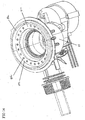
- a thrust race 80 is provided towards the outer periphery behind the second surface 22 of the control member 14.
- the thrust race 80 bears against the back of the support structure 24, along the outer surface of the base wall 24a.
- the thrust race 80 is illustrated in Figure 14, which shows the open side of the first half 8 of the housing.
- the thrust race 80 includes a cage 82 holding captive a plurality of rotatable components 84.
- the rotatable components 84 are ball bearings such that the thrust race 80 is formed as a ball race.
- the cage 82 is a moulded plastics material component holding the ball bearings 84 captive.
- first half 8 and the second half 10 of the housing together form a first generally cylindrical wall 8a, 10a defining an inlet cavity for receiving the peripheral wall 24b of the support structure 24.
- the first half 8 also includes a second generally cylindrical wall 8b defining the outlet cavity for receiving the hollow shaft 26.
- the first half 8 of the housing is then provided with a generally perpendicular lip 8c which joins the first and second generally cylindrical walls. As illustrated, this lip 8c provides a shelf on which the thrust race 80 rests.
- the force exerted by the water inlets 2,4 on the control member 14 are directed straight through the support structure 24 onto the thrust race 80 and to the lip 8c of the housing.
- the support structure 24 and shaft 26 need not be constructed so as to resist the twisting forces which would otherwise be produced in them by the water inlets. Forces are transmitted directly through the peripheral wall 24b of the support structure.
- the various mixing elements in the apparatus provide resistance to flow through the apparatus. As a result of this, some back pressure occurs where the inlets 2, 4 meet the control member 14. Furthermore, since the apertures 16, 18 are elongate with respect to the sealing cup seals 50, water is able to pass through one of those apertures 16, 18 from the respective inlet 2, 4 and then pass back out through the same aperture 16, 18 along side the inlets 2, 4. Where the apparatus is set towards full hot or full cold or where the supply pressure for the two inlets is very different, leakage of water in this way can have a significant effect on the mixed water temperature. In particular, water may leak around the outside of the support 24 to the outlet cavity 72 around the hollow shaft 26.
- the apparatus is provided with a seal 170.
- the seal 170 is annular in shape and seals between the inner surface of the walls of the first half 8 of the housing and an outer surface of the shaft 26.
- the seal 170 is positioned upstream of the outlet opening 70 and the outlet 6. In this way, water passing between the support 24 and the housing does not reach the outlet cavity 72.
- the seal ,170 is a V-seal such that its sealing ability increases as the differential pressure increases. In fact, this differential pressure will not be very high, since it results only from the back pressure caused from the mixing elements.
- the housing is formed of a first half 8 and a second half 10. Clearly, it is necessary to assemble these two halves together in such a manner that they seal correctly.
- first half 8 and second half 10 it might be possible for the first half 8 and second half 10 to be screwed together by means of threads on the respective halves. However, it would then be very difficult to ensure correct rotational alignment between the first and second halves when they had been fully rotated and tightened into a sealing engagement.
- O-rings are provided in grooves or channels.
- a mould which separates along a line running through the O-ring channel. In practice, this inevitably results in a slight ridge in the moulded plastic, thereby potentially damaging the O-ring itself or at least affecting its sealing properties.
- the first half 8 includes a step 90 into which an O-ring 92 is fitted.
- the first half also includes a lip 94.
- the second half 10 of the housing includes an outwardly extending flange 96 at the end of which there is an axially extending flange 98.
- the outwardly extending flange 96 and axially extending portion 98 of the second half 10 mate with the lip 94 of the first half 8. This mating is arranged such that the O-ring 92 is squeezed by the correct amount to achieve the required sealing. In particular, with the first and second halves 8,10 held in this position, correct sealing is achieved.
- join between the moulds for producing the first half 8 may run around a radial periphery of the first half 8, for instance around the edge of lip 94. In this way, the seating of the O-ring 92 need not be disturbed.
- a collar 100 is provided.
- the collar 100 fits around the lip 94 of the first half 8 and the portions 96, 98 of the second half 10 so as to prevent them from separating.
- the collar merely holds the first and second halves 8, 10 together in the correct position so that the O-ring 92 provides the correct sealing force.
- the force holding the collar 100 in place is radially inwardly of the lip 94 and portions 96, 98. Hence, the force is perpendicular to that needed to hold the first and second halves 8, 10 together.
- no great force is required to hold the collar 100 in place, but, with the collar in place, it can withstand considerable forces resulting from internal pressure trying to separate the first and second halves 8, 10.
- the cross-section of the collar 100 it is also possible for the cross-section of the collar 100 to have inner support surfaces 102,104 which diverge slightly.
- the lip 94 of the first half 8 and the outwardly extending flange 96 of the second half 10 are angled by a corresponding amount.
- some of the axial separating force is transferred by means of the diverging surfaces to an outward radial force.
- the strength of the cross-section of the collar 100 need not be the limiting factor in holding the first and second halves together.
- increased internal pressures may be resisted. This may be achieved, for instance, by tightening a metal band around the outer periphery of the collar 100.
- the shaft 26 extends through an aperture 27 in the first half 8 at the bottom of the outlet cavity 72 such that it may be rotated, for instance by the motor 28.
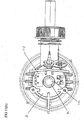
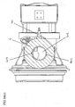
- FIGS 15(a) and (b) illustrate the apparatus with the motor 28 removed.
- the shaft 26 includes a zero position indicator 110.
- the position of the zero indicator 110 around the periphery indicates the rotational orientation of the control member 14 within the valve housing.
- a zero detector 112 is provided on the outer surface of the housing such that whenever the zero position indicator 110 actuates the zero position detector 112, an associated control system can determine the position of the control member.
- the zero position detector 112 is actuated at a particular single rotational position.
- actuation of the zero position detector 112 indicates the fully shut off position of the valve.
- the motor 28 can merely rotate the control member 14 continuously until the zero position detector 112 is actuated such that the system then knows that this is the shut off position.
- the zero position indicator 110 and zero position detector 112 may be embodied in a number of different ways.
- a cam may be provided on or connected to the shaft 26 in conjunction with a micro switch on the housing.
- the zero position indicator 110 comprises an indent in the outer periphery of the shaft 26 which is sensed by the detector 112.
- the zero position detector may be a photo detector responding to some marking or protrusion connected to the shaft 26.
- the zero position indicator 110 extends axially along the shaft 26 so that the detector 112 does not need to be located accurately in an axial direction.
- the detector may be mounted to the outer surface of the housing on pins at a predetermined angular position.
- valve will not operate correctly with the inlets reversed as the valve may give full hot instead of simply shutting down.
- FIG. 15(a) and (b) illustrate the repositioning of the zero position detector 112.
- the opposite position will be an opposite diametric position relative to the shaft 26 and control member 14 and the control system will view the shut off position as being 180 degrees from the current position and will reset the control member 14 to that new position.
- the shut off position may be some other angle from the current position. From the new position, rotation of the control member 14 will first open the cold water supply as expected.
- the zero position detector Rather than move the zero position detector on the housing, it is also possible to provide two diametrically opposed zero position detectors.
- the appropriate detector can be connected manually by the user according to observed operation of the valve.
- the control system could automatically enable the zero position detector which provides correct functioning of the valve.
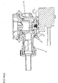
- the valve may include a temperature sensor 30 for sensing the temperature of the water mixed from the inlet valves 2 and 4.
- valve When the valve is shut off, it is possible for water to drain out of the mixing chamber 12 and outlet 6. Hence, components within the valve may dry, leaving scale behind. This can be particularly damaging to temperature sensors such as thermistors.
- the temperature sensor 30 is provided in the outlet cavity 72 immediately adjacent the outlet 6.
- flow from the plurality of openings 70 in the hollow shaft 26 to the outlet 6 will move directly past the temperature sensor 30 such that the temperature sensor 30 responds directly to the mixed water flow currently leaving the outlet 6.
- the apparatus is orientated with the rotational axis of the control member 14 horizontal and the outlet horizontal, when water is drained from the outlet 6, since the temperature sensor 30 is located centrally with respect to the outlet, it is above the lower lip of the outlet and hence above water held in the outlet cavity 72.
- the temperature sensor 30 should be positioned below the lowest point from which water will drain from the outlet cavity 72.
- the apparatus will be provided with means by which to mount it to a wall, ceiling, floor etc. Depending on the particular installation constraints, it is useful to be able to mount the apparatus in various different orientations. On the basis that it will be mounted to a horizontal or vertical surface, there are six basic possible orientations, namely the three mutually perpendicular axes and the two opposite directions for each axis.
- the apparatus In practice, there may be constraints as to how the apparatus is mounted in view of the space available. Hence, it is proposed that the apparatus should be mountable in three mutually perpendicular orientations and that in all of these orientations the temperature sensor 30 still remains submerged in water when the water is allowed to drain from the apparatus by gravity. In other words, when the valve is turned off between uses.
- the temperature 30 will remain submerged. Also, with the temperature sensor 30 located just outside the diameter of the outlet opening, the outlet 6 can be oriented horizontal with the temperature sensor 30 still below the lower lip of the outlet opening and hence still remaining submerged in the outlet cavity 72.
- the outlet orifice may be slanted with respect to the housing such that when the housing is mounted, the orifice is slanted with respect to the horizontal and vertical.
- the temperature sensor 30 must be positioned below those planes so as, once again, to remain submerged.
- the temperature sensor 30 is mounted outside the diameter of the outlet orifice, it is mounted centrally with respect to the orifice, ie along an extension of the outlet opening.
- the apparatus on its side, ie with the outlet opening in a vertical plane, water will drain from the cavity 72 so as to leave the temperature sensor 30 exposed.
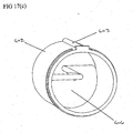
- the insert 400 comprises an outer cylindrical wall 402 to be received in the outlet 6.
- the insert 400 seals with the outlet 6 and, in this regard, may be constructed of a resilient material for push fitting into the outlet 6. It may also include means, such as the ridge 403, to interact with the outlet 6 and ensure a correct relative orientation.
- the insert 400 further includes a baffle 404 within the cylindrical wall 402.
- the baffle 404 comprises a helical or spiral section similar to an Archimedean screw. The centre of that helical section is offset with respect to the centre of the cylinder 402 and, hence, the outlet 6. The offset is designed to be sufficient to encompass the width of the temperature sensor 30 which is positioned centrally with respect to the outlet 6. Hence, if the temperature sensor 30 were offset, then the helical baffle 404 would not need to go beyond the half way line.
- the baffle 404 provides a lip in the outlet 6 which is higher than the temperature sensor 30. Thus, when water is allowed to drain from the apparatus, it is retained in the outlet cavity 72 up to the level of the baffle 404 and the temperature sensor 30 remains submerged.
- the outlet 6 remains relatively unrestricted.
- the internal cross-sectional area of the outlet 6 is only reduced by the thickness of the spiral section, rather than the overall cross-sectional area of the baffle. In other words, during normal flow, the water is merely caused to rotate.
- the outlet orifice and/or the outlet are not arranged parallel to the horizontal or vertical when the device is mounted.
- the lowest point of the baffle can be considered to form an effective boundary, ie the level at which the baffle is effective in restricting flow of water during draining. Where the horizontal plane passes through this effective boundary, the temperature sensor should be positioned below the plane. In this way, the baffle will ensure that the temperature sensor 30 remains submerged.
- FIGS 18(a) and (b) illustrate an alternative arrangement.
- the housing of the valve is arranged such that the active part of temperature sensor 530 extends into a portion of the valve housing which will retain water after water is drained out of the valve housing through the outlet 506.
- the housing of the valve is arranged such that the temperature sensor 530 or at least its tip extends into a recessed portion 520.
- This recessed portion 520 is arranged such that in three perpendicular orientations and the orientations between them, when water is drained from the valve housing, a small pocket of water will remain in the recess 520 keeping the temperature sensor 530 submerged.
- the valve will be provided in some form of generally rectangular casing for installation in a building.
- the valve 30 is arranged in the valve housing such that with the valve mounted within the casing, of the six possible orientations of the casing, in three mutually perpendicular orientations, the temperature sensor 30 will remain immersed in water.
- the temperature sensor will also remain submerged for orientations between those three perpendicular orientations.
Claims (10)
- Wassermischventil mit;einem Gehäuse (8, 10);zwei Wassereinlässen (2, 4);einer Mischkammer (12);einer Steueranordnung (14, 24, 26), welche im Verhältnis zum Gehäuse (8, 10) drehbar ist und Öffnungen (16, 18) zum Steuern des Flusses von den Wassereinlässen (2, 4) zur Mischkammer (12) hat; undeiner Nullstellungsanzeige (110), die an der Steueranordnung (14, 24, 26) vorgesehen ist; dadurch gekennzeichnet, dass:das Wassermischventil ferner:einen Nullstellungsdetektor (112) aufweist, der zum Detektieren der Nullstellungsanzeige (110) an dem Gehäuse (8, 10) so befestigt ist, dass bei Detektieren der Nullstellungsanzeige (110) bei einer vorbestimmten Stellung durch den Nullstellungsdetektor (112) ermittelt wird, dass sich die Öffnungen bezüglich der Einlässe (2, 4) an einer festgelegten, drehbaren Position befinden.
- Wassermischventil nach Anspruch 1, dadurch gekennzeichnet, dass die Steueranordnung (14, 24, 26) ein Steuerelement (14) umfasst, wobei sich die Öffnungen (16, 18) und Welle (26) axial von dem Steuerelement (14) erstrecken, wobei die Steueranordnung durch die Welle (26) drehbar ist und die Nullstellungsanzeige (110) an einer vorbestimmten Position um den Umfang der Welle (26) fern des Steuerelements (14) vorgesehen ist.
- Wassermischventil nach Anspruch 2, dadurch gekennzeichnet, dass sich die Stellungsanzeige (110) in einer bezüglich der Öffnungen (16, 18) vorbestimmten relativen Drehausrichtung befindet.
- Wassermischventil nach Anspruch 2. oder 3, dadurch gekennzeichnet, dass sich die Nullstellungsanzeige (110) axial entlang der Welle (26) erstreckt, so dass sie an verschiedenen Positionen entlang der Welle (26) detektiert werden kann.
- Wassermischventil nach Anspruch 2, 3 oder 4, dadurch gekennzeichnet, dass das Steuerelement (14) und die Welle (26) in dem Gehäuse (8, 10) gelagert sind, wobei das Gehäuse (8, 10) eine Antriebsöffnung (27) bildet, durch die sich die Welle (26) so erstreckt, dass sie von außerhalb des Gehäuses (8, 10) drehbar ist, wobei die Nullstellungsanzeige (110) außerhalb des Gehäuses (8, 10) positioniert ist.
- Wassermischventil nach Anspruch 5, dadurch gekennzeichnet, dass das Gehäuse (8, 10) eine äußere Fläche um die Welle (26) umfasst und der Nullstellungsdetektor (112) an der an die Welle (26) angrenzenden äußeren Fläche befestigt ist.
- Wassermischventil nach Anspruch 6, dadurch gekennzeichnet, dass mehrere Detektor-Halterungen an der äußeren Fläche um die Welle (26) vorgesehen sind, wobei jede Detektor-Hallerung zum Aufnehmen des Nullstellungsdetektors (110) dient.
- Wassermischventil nach Anspruch 7, dadurch gekennzeichnet, dass zwei Detektor-Halterungen vorgesehen sind, wovon eine bezüglich der Welle (26) der anderen diametral gegenüberliegt.
- Wassermischventil nach einem der vorhergehenden Ansprüche, dadurch gekennzeichnet, dass die Nullstellungsanzeige (110) ein Nocken, beispielsweise eine Aussparung oder ein Vorsprung, ist.
- Wassermischventil nach einem der vorhergehenden Ansprüche, dadurch gekennzeichnet, dass der Nullstellungdetektor (112) einen Mikroschalter umfasst.
Applications Claiming Priority (4)
| Application Number | Priority Date | Filing Date | Title |
|---|---|---|---|
| GB0004674 | 2000-02-28 | ||
| GB0004674A GB2359610A (en) | 2000-02-28 | 2000-02-28 | Water mixing valve |
| EP20040021109 EP1482221B1 (de) | 2000-02-28 | 2001-02-28 | Mischventil für Wasser |
| EP20010301823 EP1128105B1 (de) | 2000-02-28 | 2001-02-28 | Mischventil für Wasser |
Related Parent Applications (1)
| Application Number | Title | Priority Date | Filing Date |
|---|---|---|---|
| EP20040021109 Division EP1482221B1 (de) | 2000-02-28 | 2001-02-28 | Mischventil für Wasser |
Publications (3)
| Publication Number | Publication Date |
|---|---|
| EP1596110A2 EP1596110A2 (de) | 2005-11-16 |
| EP1596110A3 EP1596110A3 (de) | 2006-02-15 |
| EP1596110B1 true EP1596110B1 (de) | 2007-11-28 |
Family
ID=9886543
Family Applications (4)
| Application Number | Title | Priority Date | Filing Date |
|---|---|---|---|
| EP20050011902 Expired - Lifetime EP1589268B1 (de) | 2000-02-28 | 2001-02-28 | Mischventil für Wasser |
| EP20010301823 Expired - Lifetime EP1128105B1 (de) | 2000-02-28 | 2001-02-28 | Mischventil für Wasser |
| EP20050011903 Expired - Lifetime EP1596110B1 (de) | 2000-02-28 | 2001-02-28 | Mischventil für Wasser |
| EP20040021109 Expired - Lifetime EP1482221B1 (de) | 2000-02-28 | 2001-02-28 | Mischventil für Wasser |
Family Applications Before (2)
| Application Number | Title | Priority Date | Filing Date |
|---|---|---|---|
| EP20050011902 Expired - Lifetime EP1589268B1 (de) | 2000-02-28 | 2001-02-28 | Mischventil für Wasser |
| EP20010301823 Expired - Lifetime EP1128105B1 (de) | 2000-02-28 | 2001-02-28 | Mischventil für Wasser |
Family Applications After (1)
| Application Number | Title | Priority Date | Filing Date |
|---|---|---|---|
| EP20040021109 Expired - Lifetime EP1482221B1 (de) | 2000-02-28 | 2001-02-28 | Mischventil für Wasser |
Country Status (4)
| Country | Link |
|---|---|
| US (1) | US6880575B2 (de) |
| EP (4) | EP1589268B1 (de) |
| DE (4) | DE60108279T2 (de) |
| GB (1) | GB2359610A (de) |
Families Citing this family (34)
| Publication number | Priority date | Publication date | Assignee | Title |
|---|---|---|---|---|
| US7717351B2 (en) | 2001-08-24 | 2010-05-18 | Margarl, LLC | Mixing valve |
| NZ517764A (en) * | 2002-03-13 | 2003-10-31 | Apex Valves Ltd | Liquid tempering valve with control piston within diverter displaceable by temperature activation sensor |
| US7694693B1 (en) * | 2002-10-08 | 2010-04-13 | Vitalwear, Inc. | Mixing valve for a contrast therapy system |
| GB2417058B (en) * | 2004-08-11 | 2008-08-13 | Aqualisa Products Ltd | Water mixing valve |
| US7913926B2 (en) * | 2006-02-17 | 2011-03-29 | Watts Water Technologies, Inc. | Thermostatic mixing valve |
| US20070215056A1 (en) * | 2006-03-16 | 2007-09-20 | Kreger Lionel L | Watering system for turkeys |
| GB2436606B (en) * | 2006-03-29 | 2010-09-15 | Aqualisa Products Ltd | Water valve assembly |
| DE602007004147D1 (de) * | 2006-06-02 | 2010-02-25 | Emech Control Ltd | Mischventil und Mischvorrichtung |
| US7753074B2 (en) | 2006-07-28 | 2010-07-13 | Masco Corporation Of Indiana | Mixing valve |
| US8578966B2 (en) * | 2006-07-28 | 2013-11-12 | Masco Corporation Of Indiana | Mixing valve |
| GB2448365B (en) * | 2007-04-13 | 2011-08-03 | Aqualisa Products Ltd | Insert for water valve outlet |
| US7806134B1 (en) * | 2007-12-05 | 2010-10-05 | Hain Yo Enterprises Co., Ltd. | Mixed water control valve having a water pressure balance function to stabilize a water temperature |
| KR101047280B1 (ko) * | 2008-05-26 | 2011-07-07 | 주식회사 한 에너지 시스템 | 이중온수탱크를 구비한 보일러시스템 |
| US20100126612A1 (en) * | 2008-11-25 | 2010-05-27 | Globe Union Industrial Corp. | Water flow temperature control system |
| JP5523083B2 (ja) * | 2009-12-21 | 2014-06-18 | 大電株式会社 | 混合弁装置 |
| US9657464B2 (en) * | 2010-05-25 | 2017-05-23 | Kerry Dunki-Jacobs | Flow control system |
| AU2012203928A1 (en) * | 2011-07-07 | 2013-01-24 | Markon Holdings Limited | A water mixing system, a sanitary fitting, a bath filling system and a system for selectively introducing an additive into a water stream |
| EP2604896B1 (de) * | 2011-12-15 | 2015-08-12 | Flühs Drehtechnik GmbH | Mischvorrichtung für Leitungswasser |
| DE102013210577A1 (de) * | 2013-05-02 | 2014-11-06 | Magna Powertrain Ag & Co. Kg | Rotationsventil |
| US10041604B2 (en) * | 2014-10-20 | 2018-08-07 | Aktiebolaget Skf | Valve operator assembly and valve equipped with such assembly |
| CN104964065A (zh) * | 2015-05-20 | 2015-10-07 | 天津斯维克阀业有限公司 | 一种冷热水控制阀 |
| CN104948774B (zh) * | 2015-06-10 | 2017-06-20 | 梁日成 | 一种控水装置 |
| US20170218608A1 (en) * | 2015-10-08 | 2017-08-03 | Chung-Chia Chen | Faucets Incorporating Valves and Sensors |
| DE102015016786A1 (de) * | 2015-12-23 | 2017-06-29 | Voss Automotive Gmbh | Aktuatoreinheit sowie Baugruppeneinheit mit zumindest einer solchen Aktuatoreinheit und zumindest einer Massenstromregel- oder Ventileinheit |
| IT201600108293A1 (it) | 2016-10-26 | 2018-04-26 | Caleffi Spa | Dispositivo valvolare miscelatore |
| WO2018089205A1 (en) * | 2016-11-10 | 2018-05-17 | Mag Aerospace Industries, Llc | Flush plate |
| CN107327596A (zh) * | 2017-06-27 | 2017-11-07 | 广州市威士丹利智能科技有限公司 | 数控恒温水龙头 |
| CN208605661U (zh) | 2018-05-14 | 2019-03-15 | 讯凯国际股份有限公司 | 控制阀 |
| CN108662197A (zh) * | 2018-08-03 | 2018-10-16 | 潍坊康斯拓普温控卫浴有限公司 | 组合式混水阀腔体 |
| BR202019009837Y1 (pt) * | 2019-05-14 | 2020-10-27 | Qbanho Industrial Ltda | disposição construtiva em distribuidor com regulador de fluxo de água potável para aplicação em qualquer pressão dotado por válvula dinâmica para ajuste e controle de vazão |
| JP7420490B2 (ja) | 2019-06-21 | 2024-01-23 | 株式会社ヒラノテクシード | バルブとそれを用いた間欠塗工装置 |
| CN110553094A (zh) * | 2019-08-30 | 2019-12-10 | 张锦花 | 一种水流温度感应控制阀 |
| US11885438B2 (en) * | 2020-03-30 | 2024-01-30 | Lancaster Flow Automation, Llc | Choke Valve |
| CN217108325U (zh) * | 2022-04-28 | 2022-08-02 | 漳州松霖智能家居有限公司 | 水路开关切换阀与淋浴器 |
Family Cites Families (41)
| Publication number | Priority date | Publication date | Assignee | Title |
|---|---|---|---|---|
| US3171441A (en) * | 1961-08-23 | 1965-03-02 | Rokal Gmbh | Mixing valves for hot and cold water |
| GB604515A (en) * | 1945-04-20 | 1948-07-06 | Gerhard Teddy Salinger | Improvements relating to mixers for liquids and particularly hot and cold water |
| US2562875A (en) * | 1946-05-07 | 1951-08-07 | Electrol Inc | Inlet water valve for automatic washing machines |
| LU35101A1 (fr) * | 1956-04-20 | Dispositif de commande en fonction de la température | ||
| US3762638A (en) * | 1968-08-26 | 1973-10-02 | D Goldsmith | Thermostatic mixing valve |
| CA957241A (en) * | 1971-04-09 | 1974-11-05 | Masco Corporation | Mixing valve |
| GB1388294A (en) * | 1972-04-28 | 1975-03-26 | Alvasum Aseptic Ltd | Pinch valves |
| US3921659A (en) * | 1973-12-19 | 1975-11-25 | Speakman Co | Modular balanced pressure mixing valve with ceramic valve elements |
| US3918678A (en) * | 1974-05-06 | 1975-11-11 | Purdue Research Foundation | Aseptic bulk material storage system and improved aseptic valve therefor |
| US3913612A (en) * | 1974-12-16 | 1975-10-21 | Price Pfister Brass Mfg | Eccentric shear seal cartridge valve |
| IT1028707B (it) * | 1975-02-28 | 1979-02-10 | Metalli Pressati Bonomi Spa | Gruppo miscelatore di acqua caloa e fredda |
| US3980229A (en) * | 1975-04-01 | 1976-09-14 | Parker-Hannifin Corporation | Temperature controlled regulator |
| GB2047552B (en) * | 1979-03-23 | 1982-10-27 | Mcmaster Christie C | Liquid mixer valve and pump assembly |
| DE3048399A1 (de) * | 1980-12-22 | 1982-07-15 | Vdo Adolf Schindling Ag, 6000 Frankfurt | Ventilanordnung |
| DE3120171A1 (de) * | 1981-05-21 | 1983-01-05 | Friedrich Grohe Armaturenfabrik Gmbh & Co, 5870 Hemer | Handhebel fuer eingriffmischventil mit stellungsanzeige |
| US4827980A (en) * | 1983-05-31 | 1989-05-09 | Mazzei Domonic J | Laundry faucet |
| GB8319853D0 (en) * | 1983-07-22 | 1983-08-24 | Forsac Valves | Ball valve for pipeline |
| NO152880C (no) * | 1983-08-30 | 1985-12-04 | Lyng Ind As | Temperaturpaavirkbar, elektronisk styrt blandeventil for blanding av to vaesker. |
| JPH0623936B2 (ja) * | 1984-03-27 | 1994-03-30 | 松下電器産業株式会社 | 湯水混合装置 |
| DE3503793C2 (de) * | 1985-02-05 | 1995-09-21 | Grohe Armaturen Friedrich | Mischventil |
| JPH0743044B2 (ja) * | 1986-06-17 | 1995-05-15 | 松下電器産業株式会社 | 湯水混合装置 |
| NZ226658A (en) * | 1987-10-27 | 1990-03-27 | Dorf Ind Pty Ltd | Single handle mixing valve including apertured discs |
| GB2212885A (en) * | 1987-12-08 | 1989-08-02 | Teng Chuan Chen | Mixer tap with water temperature adjusting device |
| US5080128A (en) * | 1989-01-30 | 1992-01-14 | Taylor Julian S | Angle body restrictor valve |
| DE3935389A1 (de) * | 1989-10-24 | 1991-04-25 | Wolf Woco & Co Franz J | Mischventil |
| GB2259130A (en) * | 1991-08-31 | 1993-03-03 | Roger Douglas Parmiter | Fluid control valve |
| GB9201978D0 (en) * | 1992-01-30 | 1992-03-18 | Mastermind Designs Limited | Shower water supply apparatus |
| DE4431435A1 (de) * | 1994-09-03 | 1996-03-07 | Grohe Armaturen Friedrich | Einhebelmischventil |
| US5445181A (en) * | 1994-09-15 | 1995-08-29 | Kohler Co. | Mixing valve |
| JP3036376B2 (ja) * | 1994-10-31 | 2000-04-24 | 松下電器産業株式会社 | 湯水混合装置 |
| US5501244A (en) * | 1994-11-14 | 1996-03-26 | Emhart Inc. | Valve assembly |
| US5487408A (en) * | 1994-11-30 | 1996-01-30 | Pokhis; Naum | Water sink system |
| US5931374A (en) * | 1995-06-27 | 1999-08-03 | Masco Corporation | Flow control ports for a thermostatic mixing faucet |
| AU1162897A (en) * | 1995-11-22 | 1997-06-11 | Mike Kenney Tool, Inc. | Distribution valve for high pressure coolant used in a metalworking machine application |
| US5826617A (en) * | 1996-01-11 | 1998-10-27 | Pokhis; Naum | Water sink system |
| US5685339A (en) * | 1996-06-25 | 1997-11-11 | Lee; Chin-Tsai | Hot/cold water flowrate control device |
| DE29704052U1 (de) * | 1997-03-06 | 1997-05-07 | Fritsche Walter | Armatur für Flüssigkeitsmischung mit integrierter Temperaturmeßeinrichtung und Temperaturanzeige allgemein, insbesondere für Einhebel- und Mehrventilmischbat terie |
| US5867900A (en) * | 1997-08-26 | 1999-02-09 | Ecowater Systems, Inc. | Plastic coated valve rotor and a method of manufacturing |
| IT1296638B1 (it) * | 1997-12-15 | 1999-07-14 | Studio Tec Sviluppo Richerche | Cartuccia o meccanismo per un rubinetto miscelatore progressivo. |
| ITTO980071A1 (it) * | 1998-01-28 | 1999-07-28 | Gevipi Ag | Coppia di piastrine in materiale duro, per un rubinetto miscelatore pr ogressivo. |
| ITTO980393A1 (it) * | 1998-05-12 | 1999-11-12 | Gevipi Ag | Valvola miscelatrice termostatica con controllo manuale progressivo. |
-
2000
- 2000-02-28 GB GB0004674A patent/GB2359610A/en not_active Withdrawn
-
2001
- 2001-02-27 US US09/794,796 patent/US6880575B2/en not_active Expired - Fee Related
- 2001-02-28 EP EP20050011902 patent/EP1589268B1/de not_active Expired - Lifetime
- 2001-02-28 DE DE2001608279 patent/DE60108279T2/de not_active Expired - Lifetime
- 2001-02-28 EP EP20010301823 patent/EP1128105B1/de not_active Expired - Lifetime
- 2001-02-28 DE DE2001631689 patent/DE60131689T2/de not_active Expired - Lifetime
- 2001-02-28 DE DE2001628603 patent/DE60128603T2/de not_active Expired - Lifetime
- 2001-02-28 EP EP20050011903 patent/EP1596110B1/de not_active Expired - Lifetime
- 2001-02-28 DE DE2001618806 patent/DE60118806T2/de not_active Expired - Lifetime
- 2001-02-28 EP EP20040021109 patent/EP1482221B1/de not_active Expired - Lifetime
Also Published As
| Publication number | Publication date |
|---|---|
| DE60128603D1 (de) | 2007-07-05 |
| DE60118806T2 (de) | 2006-10-19 |
| DE60128603T2 (de) | 2008-01-31 |
| GB0004674D0 (en) | 2000-04-19 |
| US6880575B2 (en) | 2005-04-19 |
| EP1596110A3 (de) | 2006-02-15 |
| EP1589268A3 (de) | 2005-12-28 |
| EP1482221B1 (de) | 2006-04-12 |
| EP1589268B1 (de) | 2007-05-23 |
| DE60108279T2 (de) | 2005-12-29 |
| EP1128105A3 (de) | 2003-03-12 |
| DE60108279D1 (de) | 2005-02-17 |
| EP1128105B1 (de) | 2005-01-12 |
| EP1589268A2 (de) | 2005-10-26 |
| EP1482221A1 (de) | 2004-12-01 |
| DE60131689T2 (de) | 2008-10-30 |
| EP1128105A2 (de) | 2001-08-29 |
| DE60131689D1 (de) | 2008-01-10 |
| GB2359610A (en) | 2001-08-29 |
| EP1596110A2 (de) | 2005-11-16 |
| DE60118806D1 (de) | 2006-05-24 |
| US20010020645A1 (en) | 2001-09-13 |
Similar Documents
| Publication | Publication Date | Title |
|---|---|---|
| EP1596110B1 (de) | Mischventil für Wasser | |
| US4979530A (en) | Modular valve assembly | |
| US7770807B2 (en) | Water valve assembly | |
| US7905424B2 (en) | Thermostatic mixing valve | |
| CN102282520B (zh) | 用于自来水的电子可调节混合装置 | |
| US5927333A (en) | Ball valve cartridge for a mixing valve | |
| US20070221740A1 (en) | Thermostatic mixing valve | |
| US20060243813A1 (en) | Thermostatic mixer with flow diverting means | |
| WO2008095094A9 (en) | Valve cartridge with improved flow rate | |
| US20030075611A1 (en) | Thermostatic control valve with fluid mixing | |
| EP0593489B1 (de) | Mischventil mit einem kugelfoermigen ventilement | |
| AU704195B2 (en) | A ball valve cartridge for a mixing valve | |
| KR100839143B1 (ko) | 유량 조절 밸브 | |
| KR101128975B1 (ko) | 유량 조절 밸브 | |
| US20210062924A1 (en) | Water outlet member of faucet | |
| JP4109552B2 (ja) | 流量調整弁およびそれを用いた給湯装置 | |
| CN218094393U (zh) | 一种混水阀及热水器 | |
| GB2330895A (en) | Pressure-equalising control device | |
| AU2011250096B2 (en) | Thermostatic valve with improved pressure balancing | |
| GB2464687A (en) | Thermostatic mixer valve | |
| WO2000008366A1 (en) | Auxiliary valve member |
Legal Events
| Date | Code | Title | Description |
|---|---|---|---|
| PUAI | Public reference made under article 153(3) epc to a published international application that has entered the european phase |
Free format text: ORIGINAL CODE: 0009012 |
|
| AC | Divisional application: reference to earlier application |
Ref document number: 1128105 Country of ref document: EP Kind code of ref document: P Ref document number: 1482221 Country of ref document: EP Kind code of ref document: P |
|
| AK | Designated contracting states |
Kind code of ref document: A2 Designated state(s): DE FR GB IT |
|
| PUAL | Search report despatched |
Free format text: ORIGINAL CODE: 0009013 |
|
| AK | Designated contracting states |
Kind code of ref document: A3 Designated state(s): DE FR GB IT |
|
| 17P | Request for examination filed |
Effective date: 20060418 |
|
| 17Q | First examination report despatched |
Effective date: 20060704 |
|
| AKX | Designation fees paid |
Designated state(s): DE FR GB IT |
|
| GRAP | Despatch of communication of intention to grant a patent |
Free format text: ORIGINAL CODE: EPIDOSNIGR1 |
|
| GRAS | Grant fee paid |
Free format text: ORIGINAL CODE: EPIDOSNIGR3 |
|
| GRAA | (expected) grant |
Free format text: ORIGINAL CODE: 0009210 |
|
| AC | Divisional application: reference to earlier application |
Ref document number: 1128105 Country of ref document: EP Kind code of ref document: P Ref document number: 1482221 Country of ref document: EP Kind code of ref document: P |
|
| AK | Designated contracting states |
Kind code of ref document: B1 Designated state(s): DE FR GB IT |
|
| REG | Reference to a national code |
Ref country code: GB Ref legal event code: FG4D |
|
| REF | Corresponds to: |
Ref document number: 60131689 Country of ref document: DE Date of ref document: 20080110 Kind code of ref document: P |
|
| ET | Fr: translation filed | ||
| PLBE | No opposition filed within time limit |
Free format text: ORIGINAL CODE: 0009261 |
|
| STAA | Information on the status of an ep patent application or granted ep patent |
Free format text: STATUS: NO OPPOSITION FILED WITHIN TIME LIMIT |
|
| 26N | No opposition filed |
Effective date: 20080829 |
|
| REG | Reference to a national code |
Ref country code: GB Ref legal event code: 732E Free format text: REGISTERED BETWEEN 20151001 AND 20151007 |
|
| REG | Reference to a national code |
Ref country code: FR Ref legal event code: PLFP Year of fee payment: 16 |
|
| REG | Reference to a national code |
Ref country code: FR Ref legal event code: PLFP Year of fee payment: 17 |
|
| REG | Reference to a national code |
Ref country code: FR Ref legal event code: PLFP Year of fee payment: 18 |
|
| PGFP | Annual fee paid to national office [announced via postgrant information from national office to epo] |
Ref country code: FR Payment date: 20180725 Year of fee payment: 18 Ref country code: IT Payment date: 20180719 Year of fee payment: 18 Ref country code: DE Payment date: 20180723 Year of fee payment: 18 |
|
| REG | Reference to a national code |
Ref country code: DE Ref legal event code: R119 Ref document number: 60131689 Country of ref document: DE |
|
| PG25 | Lapsed in a contracting state [announced via postgrant information from national office to epo] |
Ref country code: DE Free format text: LAPSE BECAUSE OF NON-PAYMENT OF DUE FEES Effective date: 20190903 |
|
| PG25 | Lapsed in a contracting state [announced via postgrant information from national office to epo] |
Ref country code: IT Free format text: LAPSE BECAUSE OF NON-PAYMENT OF DUE FEES Effective date: 20190228 Ref country code: FR Free format text: LAPSE BECAUSE OF NON-PAYMENT OF DUE FEES Effective date: 20190228 |
|
| PGFP | Annual fee paid to national office [announced via postgrant information from national office to epo] |
Ref country code: GB Payment date: 20200218 Year of fee payment: 20 |
|
| REG | Reference to a national code |
Ref country code: GB Ref legal event code: PE20 Expiry date: 20210227 |
|
| PG25 | Lapsed in a contracting state [announced via postgrant information from national office to epo] |
Ref country code: GB Free format text: LAPSE BECAUSE OF EXPIRATION OF PROTECTION Effective date: 20210227 |