EP1595709A2 - Dispositif d'impression d'images - Google Patents
Dispositif d'impression d'images Download PDFInfo
- Publication number
- EP1595709A2 EP1595709A2 EP05252625A EP05252625A EP1595709A2 EP 1595709 A2 EP1595709 A2 EP 1595709A2 EP 05252625 A EP05252625 A EP 05252625A EP 05252625 A EP05252625 A EP 05252625A EP 1595709 A2 EP1595709 A2 EP 1595709A2
- Authority
- EP
- European Patent Office
- Prior art keywords
- paper feeding
- recording medium
- manual paper
- feeding operation
- conveying path
- Prior art date
- Legal status (The legal status is an assumption and is not a legal conclusion. Google has not performed a legal analysis and makes no representation as to the accuracy of the status listed.)
- Granted
Links
Images


Classifications
-
- B—PERFORMING OPERATIONS; TRANSPORTING
- B41—PRINTING; LINING MACHINES; TYPEWRITERS; STAMPS
- B41J—TYPEWRITERS; SELECTIVE PRINTING MECHANISMS, i.e. MECHANISMS PRINTING OTHERWISE THAN FROM A FORME; CORRECTION OF TYPOGRAPHICAL ERRORS
- B41J13/00—Devices or arrangements of selective printing mechanisms, e.g. ink-jet printers or thermal printers, specially adapted for supporting or handling copy material in short lengths, e.g. sheets
- B41J13/10—Sheet holders, retainers, movable guides, or stationary guides
- B41J13/103—Sheet holders, retainers, movable guides, or stationary guides for the sheet feeding section
-
- B—PERFORMING OPERATIONS; TRANSPORTING
- B41—PRINTING; LINING MACHINES; TYPEWRITERS; STAMPS
- B41J—TYPEWRITERS; SELECTIVE PRINTING MECHANISMS, i.e. MECHANISMS PRINTING OTHERWISE THAN FROM A FORME; CORRECTION OF TYPOGRAPHICAL ERRORS
- B41J11/00—Devices or arrangements of selective printing mechanisms, e.g. ink-jet printers or thermal printers, for supporting or handling copy material in sheet or web form
- B41J11/36—Blanking or long feeds; Feeding to a particular line, e.g. by rotation of platen or feed roller
- B41J11/38—Manually-operated feeding devices
-
- B—PERFORMING OPERATIONS; TRANSPORTING
- B41—PRINTING; LINING MACHINES; TYPEWRITERS; STAMPS
- B41J—TYPEWRITERS; SELECTIVE PRINTING MECHANISMS, i.e. MECHANISMS PRINTING OTHERWISE THAN FROM A FORME; CORRECTION OF TYPOGRAPHICAL ERRORS
- B41J11/00—Devices or arrangements of selective printing mechanisms, e.g. ink-jet printers or thermal printers, for supporting or handling copy material in sheet or web form
- B41J11/48—Apparatus for condensed record, tally strip, or like work using two or more papers, or sets of papers, e.g. devices for switching over from handling of copy material in sheet form to handling of copy material in continuous form and vice versa or point-of-sale printers comprising means for printing on continuous copy material, e.g. journal for tills, and on single sheets, e.g. cheques or receipts
-
- B—PERFORMING OPERATIONS; TRANSPORTING
- B65—CONVEYING; PACKING; STORING; HANDLING THIN OR FILAMENTARY MATERIAL
- B65H—HANDLING THIN OR FILAMENTARY MATERIAL, e.g. SHEETS, WEBS, CABLES
- B65H5/00—Feeding articles separated from piles; Feeding articles to machines
- B65H5/26—Duplicate, alternate, selective, or coacting feeds
-
- H—ELECTRICITY
- H04—ELECTRIC COMMUNICATION TECHNIQUE
- H04N—PICTORIAL COMMUNICATION, e.g. TELEVISION
- H04N1/00—Scanning, transmission or reproduction of documents or the like, e.g. facsimile transmission; Details thereof
- H04N1/00567—Handling of original or reproduction media, e.g. cutting, separating, stacking
- H04N1/0057—Conveying sheets before or after scanning
-
- H—ELECTRICITY
- H04—ELECTRIC COMMUNICATION TECHNIQUE
- H04N—PICTORIAL COMMUNICATION, e.g. TELEVISION
- H04N1/00—Scanning, transmission or reproduction of documents or the like, e.g. facsimile transmission; Details thereof
- H04N1/00567—Handling of original or reproduction media, e.g. cutting, separating, stacking
- H04N1/0057—Conveying sheets before or after scanning
- H04N1/00588—Conveying sheets before or after scanning to the scanning position
-
- H—ELECTRICITY
- H04—ELECTRIC COMMUNICATION TECHNIQUE
- H04N—PICTORIAL COMMUNICATION, e.g. TELEVISION
- H04N1/00—Scanning, transmission or reproduction of documents or the like, e.g. facsimile transmission; Details thereof
- H04N1/00567—Handling of original or reproduction media, e.g. cutting, separating, stacking
- H04N1/0057—Conveying sheets before or after scanning
- H04N1/00599—Using specific components
- H04N1/00602—Feed rollers
-
- H—ELECTRICITY
- H04—ELECTRIC COMMUNICATION TECHNIQUE
- H04N—PICTORIAL COMMUNICATION, e.g. TELEVISION
- H04N1/00—Scanning, transmission or reproduction of documents or the like, e.g. facsimile transmission; Details thereof
- H04N1/00567—Handling of original or reproduction media, e.g. cutting, separating, stacking
- H04N1/0057—Conveying sheets before or after scanning
- H04N1/00599—Using specific components
- H04N1/00604—Transport trays
-
- H—ELECTRICITY
- H04—ELECTRIC COMMUNICATION TECHNIQUE
- H04N—PICTORIAL COMMUNICATION, e.g. TELEVISION
- H04N1/00—Scanning, transmission or reproduction of documents or the like, e.g. facsimile transmission; Details thereof
- H04N1/00567—Handling of original or reproduction media, e.g. cutting, separating, stacking
- H04N1/0062—Removing sheets from a stack or inputting media
-
- H—ELECTRICITY
- H04—ELECTRIC COMMUNICATION TECHNIQUE
- H04N—PICTORIAL COMMUNICATION, e.g. TELEVISION
- H04N1/00—Scanning, transmission or reproduction of documents or the like, e.g. facsimile transmission; Details thereof
- H04N1/00567—Handling of original or reproduction media, e.g. cutting, separating, stacking
- H04N1/00631—Ejecting or stacking
-
- H—ELECTRICITY
- H04—ELECTRIC COMMUNICATION TECHNIQUE
- H04N—PICTORIAL COMMUNICATION, e.g. TELEVISION
- H04N1/00—Scanning, transmission or reproduction of documents or the like, e.g. facsimile transmission; Details thereof
- H04N1/00567—Handling of original or reproduction media, e.g. cutting, separating, stacking
- H04N1/00639—Binding, stapling, folding or perforating, e.g. punching
-
- B—PERFORMING OPERATIONS; TRANSPORTING
- B65—CONVEYING; PACKING; STORING; HANDLING THIN OR FILAMENTARY MATERIAL
- B65H—HANDLING THIN OR FILAMENTARY MATERIAL, e.g. SHEETS, WEBS, CABLES
- B65H2407/00—Means not provided for in groups B65H2220/00 – B65H2406/00 specially adapted for particular purposes
- B65H2407/20—Means not provided for in groups B65H2220/00 – B65H2406/00 specially adapted for particular purposes for manual intervention of operator
- B65H2407/21—Manual feeding
-
- H—ELECTRICITY
- H04—ELECTRIC COMMUNICATION TECHNIQUE
- H04N—PICTORIAL COMMUNICATION, e.g. TELEVISION
- H04N1/00—Scanning, transmission or reproduction of documents or the like, e.g. facsimile transmission; Details thereof
- H04N1/04—Scanning arrangements, i.e. arrangements for the displacement of active reading or reproducing elements relative to the original or reproducing medium, or vice versa
- H04N1/12—Scanning arrangements, i.e. arrangements for the displacement of active reading or reproducing elements relative to the original or reproducing medium, or vice versa using the sheet-feed movement or the medium-advance or the drum-rotation movement as the slow scanning component, e.g. arrangements for the main-scanning
-
- H—ELECTRICITY
- H04—ELECTRIC COMMUNICATION TECHNIQUE
- H04N—PICTORIAL COMMUNICATION, e.g. TELEVISION
- H04N1/00—Scanning, transmission or reproduction of documents or the like, e.g. facsimile transmission; Details thereof
- H04N1/04—Scanning arrangements, i.e. arrangements for the displacement of active reading or reproducing elements relative to the original or reproducing medium, or vice versa
- H04N1/19—Scanning arrangements, i.e. arrangements for the displacement of active reading or reproducing elements relative to the original or reproducing medium, or vice versa using multi-element arrays
- H04N1/195—Scanning arrangements, i.e. arrangements for the displacement of active reading or reproducing elements relative to the original or reproducing medium, or vice versa using multi-element arrays the array comprising a two-dimensional [2D] array
Definitions
- the present invention relates to an image recording apparatus such as a copying machine, a printer, a facsimile machine, or a multifunction imaging apparatus that is configured to record an image on a recording medium such as a sheet or an OHP film.
- an image recording apparatus such as a copying machine, a printer, a facsimile machine, or a multifunction imaging apparatus that is configured to record an image on a recording medium such as a sheet or an OHP film.
- a recording medium that is accommodated within a recording medium accommodating unit such as a paper feeding cassette is conveyed through a recording medium conveying path to be automatically fed to an image recording unit.
- the recording medium is conveyed through the image recording unit while a recording operation is conducted thereon, and the recording medium with an image recorded thereon is discharged out of the image recording unit.
- the inkjet printer may be configured to realize printing through manual paper feeding in addition to printing through automatic paper feeding as is described above.
- a special recording medium such as a thick paper sheet, a glossy paper sheet, or an OHP film may be manually inserted into the printer, one sheet at a time, and the inserted sheet may pass through a straight manual paper feeding path to reach the recording medium conveying path, after which the recording medium is fed to the image recording unit.
- an image recording apparatus has been proposed in the prior art that includes a shutter member arranged at a manual paper feeding opening, the shutter member being designed to be manually opened upon conducting a manual paper feeding operation.
- the shutter member has to be manually opened upon conducting a manual paper feeding operation.
- the recording medium has to be inserted through a narrow manual paper feeding opening, and a guide member such as a manual paper feeding tray for guiding the recording medium is not provided. Thereby, the operability of manual paper feeding may be poor.
- an image recording apparatus configured to conduct an automatic paper feeding operation and a manual paper feeding operation, the image recording apparatus including:
- a recording medium such as a paper sheet that is accommodated within a recording medium accommodating unit such as a paper feeding cassette, a paper feeding tray, or a paper feeding apparatus is automatically fed to an image recording unit such as an inkjet engine unit via a recording medium conveying path.
- a recording medium such as a thick paper sheet, a glossy paper sheet, or an OHP film is manually inserted so that the recording medium is introduced into the recording medium conveying path via a manual paper feeding tray and fed to the image recording unit.
- an image recording apparatus configured to conduct an automatic paper feeding operation and a manual paper feeding operation, the image recording apparatus including:
- the image recording apparatus further includes:
- an emergency halt operation for halting the automatic paper feeding operation is conducted.
- a warning message is generated signaling that the automatic paper feeding operation is currently being conducted.
- the automatic paper feeding operation is disabled after the manual paper feeding tray is switched from the retracted state to the used state.
- the image recording apparatus further includes a detection switch that is arranged to be turned on and off in accordance with the switching of the manual paper feeding tray between the retracted state and the used state.
- an image recording apparatus configured to conduct an automatic paper feeding operation and a manual paper feeding operation, the image recording apparatus including:
- FIG.1 is a diagram showing an internal configuration of an inkjet image recording apparatus according to an embodiment of the present invention.
- the inkjet image recording apparatus of FIG.1 includes an image recording apparatus main body 100 having a top face that is formed into a recessed portion, a delivery stack unit 200 that is provided at the recessed portion of the apparatus main body 100, a scanner unit 300 for reading a document image that is provided on top of the delivery stack unit 200, and a document holding board 400 that is provided on the scanner unit 300 and is configured to be freely opened and closed in up-down directions.
- the image recording apparatus main body 100 includes an inkjet engine unit 10 as an image recording unit that is provided around a central portion of the apparatus main body 100, a recording medium accommodating unit 14 that is provided at a lower portion of the apparatus main body and is configured to stack recording media 12 such as paper sheets, and a recording medium conveying path 16 that extends slightly upward from one end of the recording medium accommodating unit 14 at one side of the apparatus main body 100, then curves inward to extend horizontally towards the other side of the apparatus main body 100 passing through the inkjet engine unit 10, then curves upward at the other side of the apparatus main body, and then makes a U-turn to reach the delivery stack unit 200.
- an inkjet engine unit 10 as an image recording unit that is provided around a central portion of the apparatus main body 100
- a recording medium accommodating unit 14 that is provided at a lower portion of the apparatus main body and is configured to stack recording media 12 such as paper sheets
- a recording medium conveying path 16 that extends slightly upward from one end of the recording medium accommodating unit 14 at one side of the apparatus main
- the apparatus main body 100 includes a manual paper feeding path 18 that extends horizontally from one side of the apparatus main body 100 and converges with the recording medium conveying path 16 before reaching the ink jet engine unit 10.
- the recording medium conveying path 16 includes a paper feeding roller 20, a separating member 21 that is pushed toward the paper feeding roller 20, a medium guide 22, a pair of resist rollers 23, a guide member 24, and an open-close guide member 25, for example. Also, at a delivery path corresponding to a portion of the recording medium conveying path 16 extending after passing through the inkjet engine unit 10, plural pairs of conveying rollers 26 and a pair of delivery rollers 27 are provided.
- the manual paper feeding path 18 includes a manual paper feeding tray 30 that is positioned at the entrance of the apparatus main body 100, and a manual paper feed conveying guide board 31 that is positioned at the point of convergence between the recording medium conveying path 16 and the manual paper feeding path 18.
- the inkjet engine unit 10 includes an endless conveying belt 40 that is held between a drive roller 41 and a driven roller 42 in a manner such that one side of the endless belt 40 extends along the recording medium conveying path 16.
- the portion of the endless belt 40 extending along the recording medium conveying path 16 is supported by a backing board 43 backing the endless belt 40 from its underside.
- the inkjet engine 10 includes a drive pulley 44 that is coaxial with the drive roller 41, a motor pulley 46 of a sub scanning motor 45, and a drive power transmitting belt 47 that is held between the drive pulley 44 and the motor pulley 46.
- the sub scanning motor 45 is rotated by the operation of its own DC motor, and drive power generated from the rotation is transmitted via the drive power transmitting belt 47 to the conveying belt 40 to induce rotation of the conveying belt 40 in a counterclockwise direction.
- an inkjet head 48 is provided facing against the conveying belt 40 with the recording medium conveying path 16 positioned in between the inkjet head 48 and the conveying belt 40. Also, the conveying belt 40 is held between the drive roller 41 and a holding roller 49 that is pushed toward the drive roller 41 from the upper side of the recording medium conveying belt 16 to form a nip with the conveying belt 40. Also, at a region close to the exit of the inkjet engine unit 10, the recording medium conveying belt 16 is held between a pair of discharge rollers 50.
- the apparatus main body 100 also includes an ink tank unit 52 provided at a lower side, the ink tank unit 52 including ink tanks of different color inks and being configured to supply ink to the inkjet head 48. Also, an HB stepping motor 53 is provided within a space created at a lower side of the medium guide 22, the HB stepping motor 53 being configured to rotate the resist roller 23.
- the scanner unit 300 is formed into a flat box structure, and includes a light source (not shown) and plural mirrors 60, a lens unit 61, an optical-electrical conversion element 62 such as a CCD, and a contact glass 63 that is provided on the top surface of the box structure.
- a document that is placed on top of the contact glass 63 may be held in place by the document holding board 400 that holds down the document from the upper side of the contact glass 63.
- the scanner unit 300 may be operated to drive a traveling unit (not shown) including the light source and mirrors, for example, so that light from the light source may be reflected at the document surface to be incident on the mirrors 60.
- the incident light is reflected by the plural mirrors 60, and an image is formed at the lens unit 61.
- the image optical signal is converted into an electrical signal at the optical-electrical conversion element 62 and the document content is read.
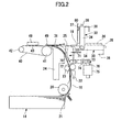
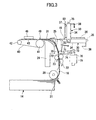
- the open/close guide member 25 is formed into a triangular shape, and may be freely rotated with respect to a lower end axis 70 between a first position that widens the recording medium conveying path 16 and a second position that narrows the recording medium conveying path 16. It is noted that normally, a spring force of a bias spring 71 is applied to the open/close guide member 25 so that the open/close guide member 25 hits against a stopper (not shown) to be set to the first position as is shown in FIG.3. When the open/close guide member 25 is set to the second position, a recording medium may be inserted into the manual paper feeding path 18.
- an arm member 72 is integrally connected to the open/close guide member 25 at its lower end axis 70 portion.
- the tip portion of the arm member 72 is connected to one end of a lever member 73 in a manner such that the lever member 73 may be freely rotated around an axis 74.
- the other end of the lever member 73 is connected to a plunger 76 of a solenoid 75.
- the solenoid 75 When the solenoid 75 is activated, the plunger 76 is pulled in, and the lever member 73 is rotated around the axis 74 in the direction of the arrow shown in FIG.2.
- the arm member 72 is raised, and the open/close guide member 25 is moved to the second position as is shown in FIG.2 against the spring force of the bias spring 71.
- the manual paper feeding tray 30 includes a main body 34 that may be freely rotated with respect to an axis 33, an extending tray 35 that may be drawn in and out of the main body 34, side edge guides 36 for the recording medium that are provided on the upper surface of the main body 34, a detection switch 37 that is also provided on the upper surface of the main body 34, and a handle 38 that is provided at the lower surface end portion of the main body 34.
- the manual paper feeding tray 30 may freely rotate around the axis 33 to move between a retracted state as is represented by solid lines in FIGS.2 and 3, and a used state as is represented by broken lines in FIGS.2 and 3.
- the detection switch 37 hits against a box structure 80 of the apparatus main body 100 and is switched on.
- the manual paper feeding path 18 includes a shutter-82.
- the shutter 82 is arranged to rotate around an axis 83, and is engaged with a plunger 85 of a shutter solenoid 84.
- the detection switch is switched from an on state to an off state indicating that a manual paper feeding operation is selected.
- the shutter solenoid 84 is turned on, and the plunger 85 is pulled in so that the shutter 82 may be rotated around the axis 83 in a direction indicated by the arrow in FIG.4 against the gravitational force to be set to an open position.
- a recording medium may be inserted into the recording medium conveying path 16 via the manual paper feeding path 18.
- the detection switch 37 is switched from an off state to an on state indicating that an automatic paper feeding operation is selected.
- the shutter solenoid 84 is turned off, and the plunger is drawn out so that the shutter 82 rotates back to a closed position according to the gravitational force. In this state, the shutter 82 blocks a recording medium from being inserted into the recording medium conveying path 16 via the manual paper feeding path 18.
- the solenoid 75 when the power of the image recording apparatus main body 100 is switched off, the solenoid 75 is in a non-operation state and the spring power of the bias spring 71 does not work on the open/close guide member 25 so that the open/close guide member 25 is positioned in the first position as is shown in FIG.3.
- the shutter solenoid 84 is also in a non-operation state, and thereby, the shutter 82 is set to a closed position as is shown in FIG.4 according to the gravitational force.
- the manual paper feeding tray 30 is preferably set to a retracted state for the sake of realizing compactness.
- the document holding board 400 when conducting a copying operation, is opened to set a document on the contact glass 63, after which the document holding board 400 is closed to hold down the document. Then, a copying switch (not shown) is pushed to activate the scanner unit 300 so that the document surface may be scanned and the document content may be read.
- the paper feeding roller 20 rotates at an appropriate timing so that a recording medium 12 may be ejected out of the recording medium accommodating unit 14 from the top. Then, the recording medium 12 is separated by the separating member 21 to be inserted into the recording medium conveying path 16. The recording medium 12 is then guided by the medium guide 22 so that its edge portion may be inserted between the pair of resist rollers 23. Then, the resist rollers 23 are rotated at an appropriate timing so that the recording medium 12 may be inserted between the guide member 24 and the open/close guide member 25 and guided by the guide members to be set within the nip formed between the conveying belt 40 and the holding roller 49.
- the edge portion of the recording medium 12 is held at the nip, this state is detected by a detector (not shown), and the operation of the solenoid 75 is stopped.
- the bias spring 71 continues applying the spring force to the open/close guide member 25 so that the open/close guide member 25 is set to the first position as is shown in FIG.3. Then, the recording medium 12 is conveyed by the conveying belt 40 that is driven by the sub scanning motor 45 at a transfer rate that is lower than the transfer rate of the resist roller 23.
- the open/close guide member 25 is set to the second position. Thereby, the recording medium 12 may be conveyed with ease even when the recording medium is curled, for example.
- the open/close guide member 25 is set to the first position so that a loop is formed at the recording medium 12 from the difference in the transfer rates between the conveying belt 40 and the resist rollers 23. In this way, the conveying performance of the image recording apparatus may be improved, and recording media 12 of differing types may be effectively conveyed without inducing a paper jam.
- the recording medium 12 that is guided to the nip formed between the conveying belt 40 and the holding roller 49 is conveyed by the conveying belt 40 to be inserted into the inkjet engine unit 10.
- the conveying belt continues to convey the recording medium 12 within the inkjet engine unit 10 while recording is conducted on the recording medium 12 by the inkjet head 48 according to the document content that is read by the scanner unit 300 as is described above.
- the recording medium is discharged out of the inkjet engine unit 10 by the pair of discharge rollers 50.
- the recording medium 12 is conveyed through the delivery path by plural pairs of delivery rollers, and is discharged onto the delivery stack unit 200 by the delivery rollers 27.
- the solenoid 75 is operated at an appropriate timing so that the lever member 73 may be rotated to raise the arm member 72.
- the open/close guide member 25 is set back to the second position as is shown in FIG.2. It is noted that by setting the open/close guide member 25 to the second position before the recording medium 12 passes through the open/close-guide member 25 and the guide member 24, a load from the recording medium 12 passing through the guide members may be prevented from working on the closing action of the open/close guide member 25, and the electromagnetic force of the solenoid 75 may be kept at a low level.
- the paper feeding roller 20 is rotated to eject the next recording medium 12 from the recording medium accommodating unit 14 and insert the recording medium 12 into the recording medium conveying path 16.
- the recording medium 12 is guided by the medium guide 22 and its edge portion is set between the pair of resist rollers 23.
- the resist rollers 23 are rotated at an appropriate timing to insert the recording medium 12 between the guide member 24 and the open/close guide member 25.
- the recording medium 12 is then guided by the guide members 24 and 25 to be set within the nip formed between the conveying belt 40 and the holding roller 49.
- the operation of the solenoid 75 is stopped and the open/close guide member 25 is set back to the first position as is shown in FIG.3.
- the recording medium 12 with its edge portion held between the nip is conveyed by the conveying belt 40 to be inserted into the inkjet engine unit 10 at which recording is conducted on the recording medium 12 by the inkjet head 48.
- the recording medium 12 is then discharged out of the inkjet engine unit 10 by the discharge rollers 50 to be conveyed through the delivery path by plural pairs of delivery rollers 26 and discharged onto the delivery stack unit 200 by the delivery rollers 27. It is noted that a similar copying process may be conducted for the next recording medium 12 as well.
- the document holding board is opened and a document is placed on the contact glass 63 after which the document holding board 400 is closed as is described above.
- the manual paper feeding tray 30 is rotated around the axis 33 by pulling the handle 38, for example, so that the manual paper feeding tray 30 may be set to a used state, and the detection switch 37 is moved away from the box structure 80 to be switched to an off state indicating that the manual paper feeding operation is selected.
- preparations are made for enabling the manual paper feeding operation as is described below.
- the solenoid 75 is activated and the open/close guide member 25 is set to the second position (closed state). Then, the shutter solenoid 84 is turned on and the plunger 85 is pulled in so that the shutter 82 is set to an open position. Then, the extending tray 35 is drawn out of the main body 34 as is shown in FIG.5. Then, a recording medium may be inserted and guided along the manual paper feeding tray 30 by the side edge guides 36, and the edge portion of the recording medium may be passed through the manual paper feeding path 18 to be set into the nip formed between the conveying belt 40 and the holding roller 49.
- the document content is read by the scanner unit 300, and recording is conducted on the recording medium by the inkjet head according to the read document content while the recording medium is conveyed by the conveying belt 40. Then, the recording medium is conveyed through the delivery path by plural pairs of conveying rollers 26 and discharged onto the delivery stack unit 200 by the delivery rollers 27.
- an image recording apparatus as is described above that is configured to realize an automatic paper feeding operation in which a recording medium 12 accommodated in the recording medium accommodating unit 14 is automatically conveyed to the inkjet engine unit (image recording unit) 10 via the recording medium conveying path 16, and a manual paper feeding operation in which a recording medium 12 that is manually inserted into the image recording apparatus is introduced into the recording medium conveying path 16 via the manual paper feeding path 18 to then be conveyed the inkjet engine unit 10, when a manual paper feeding operation is conducted while an automatic paper feeding operation is conducted, or when an automatic paper feeding operation is being conducted while a manual paper feeding operation is being conducted, plural recording media 12 may be inserted into the recording medium conveying path 16 at once to thereby cause a paper jam.
- the manual paper feeding tray 30 when the manual paper feeding tray 30 is set to the retracted state, the automatic feeding operation is selected and the manual paper feeding tray 30 hinders a manually inserted recording medium from being introduced into the recording medium conveying path 16 via the manual paper feeding path 18.
- the manual paper feeding tray 30 in order to conduct a manual paper feeding operation, the manual paper feeding tray 30 has to be switched to the used state.
- a manual paper feeding operation may be prevented from being mistakenly conducted while an automatic paper feeding operation is conducted so that occurrence of a paper jam may be prevented.
- the manual paper feeding tray 30 when the manual paper feeding tray 30 is set to the used state, the manual feeding operation is selected and the manual paper feeding tray 30 is arranged to allow a manually inserted recording medium to be introduced into the recording medium conveying path 16 via the manual paper feeding path 18.
- a shutter member does not have to be manually opened, and the manually inserted recording medium may be guided by the manual paper feeding tray in the manual paper feeding operation, and thereby, the operability of manual paper feeding may be improved.
- the shutter 82 that may be opened and closed is provided.
- the shutter When the manual paper feeding tray 30 is set to a retracted state so that the automatic paper feeding operation is selected, the shutter is arranged to be in a closed position so that the manual paper feeding path may be blocked by the shutter 82. In this way, a recording medium 12 may be prevented from being inserted into the recording medium conveying path 16 via the manual paper feeding path 18. Accordingly, a paper jam may be prevented from occurring as a result of mistakenly conducting a manual paper feeding operation while an automatic paper feeding operation is being conducted. Also, when the manual paper feeding operation is being conducted, the shutter is arranged to be set to an open position so that a recording medium 12 may be inserted into the recording medium conveying path 16 via the manual paper feeding path 18. Thereby, the shutter 82 does not have to be manually opened, and the recording medium that is manually fed to the image recording apparatus may be guided by the manual paper feeding tray 30 so that operability of manual paper feeding may be improved.
- an automatic feeding operation is selected and the shutter 82 is set to a closed position.
- the manual paper feeding operation is selected and the shutter 82 is set to an open position.
- the automatic paper feeding operation is halted by an emergency halt operation.
- a paper jam caused by the overlapping of a recording medium 12 fed by an automatic paper feeding operation and a recording medium 12 fed by a manual paper feeding operation within the recording medium conveying path 16 may be prevented from occurring as a result of mistakenly conducting a manual paper feeding operation while an automatic paper feeding operation is being conducted.
- a warning message may be generated signaling that an automatic paper feeding operation is currently being conducted.
- the user receiving the warning message may be informed of the fact that a paper jam may possibly occur if a manual paper feeding operation is presently conducted.
- the user may wait until the automatic paper feeding operation is finished before starting a manual paper feeding operation in order to prevent trouble beforehand.
- the automatic paper feeding operation is disabled.
- an automatic paper feeding operation may be prevented from being conducted while a manual paper feeding operation is being conducted so that a recording medium 12 fed through manual paper feeding and a recording medium 12 fed through automatic paper feeding may be prevented from being inserted into the recording medium conveying path 16 at the same time, and a paper jam may be prevented from occurring as a result of such an overlap of recording media 12 in the recording medium conveying path 16.
- a detection switch 37 is provided that is turned on or off according to the switching of the manual paper feeding tray 30 between a retracted state and a used state. In this way, it may be easily determined whether the manual paper feeding tray 30 is in a retracted state or a used state by means of the detection switch 37, and distinction between an automatic paper feeding operation and a manual paper feeding operation may be swiftly and automatically determined to thereby conduct necessary control operations according to the currently selected paper feeding operation.
- an open/close guide member 25 that guides a recording medium 12 to the recording medium conveying path 16 when the automatic paper feeding operation is conducted, the open/close guide member 25 being arranged to be rotated between a first position that widens the recording medium conveying path 16 and a second position that narrows the recording medium conveying path 16.
- the open/close guide member 25 is set to the second position while the tip portion of the recording medium 12 is passing the open/close guide member 25, and thereby, the recording medium 12 may be easily conveyed even when the recording medium 12 is curled.
- the open/close guide member 25 is set to the first position after the tip portion of the recording medium 12 passes through the open/close guide member 25 to thereby widen the recording medium conveying path 16 so that a loop may be created at the recording medium 12. In this way, conveying performance maybe improved, and various types of recording media 12 may be effectively conveyed without jamming.
- the open/close guide member 25 when the automatic paper feeding operation is conducted, the open/close guide member 25 is set to the first position and hinders a manually inserted recording medium from being introduced into the recording medium conveying path via the manual paper feeding path. Thereby, a paper jam may be prevented from occurring as a result of mistakenly conducting a manual paper feeding operation while an automatic paper feeding operation is conducted.
- the open/close guide member 25 when the manual paper feeding operation is conducted, the open/close guide member 25 is set to the second position to allow a manually inserted recording medium 12 to be introduced into the recording medium conveying path 16 via the manual paper feeding path 18. In this way, the open/close guide member 25 is arranged to rotate in conjunction with the paper feeding operation being conducted so that the and the manually inserted recording medium may be guided by the manual paper feeding tray 30. Thereby, operability of manual paper feeding may be improved.
- the shutter 82 is provided separately from the manual paper feeding tray 30, and when conducting an automatic paper feeding operation, the shutter 82 is arranged to block the manual paper feeding path 18 to prevent a recording medium 12 from being inserted into the recording medium conveying path 16 via the manual paper feeding path 18.
- the present invention is not limited to such an arrangement, and for example, instead of providing the shutter 82, the manual paper feeding tray 30 may be arranged to block the manual paper feeding path 18 when it is set to a retracted state so that a recording medium 12 may be prevented from being inserted into the recording medium conveying path 16 via the manual paper feeding path 18.
- the open/close guide member 25 when the open/close guide member 25 is set to the first position, the open/close guide member 25 may be arranged to block the manual paper feeding path 18 to prevent a recording medium 12 from being inserted into the recording medium conveying path 16 via the manual paper feeding path 18. That is, a recording medium 12 fed through automatic paper feeding and a recording medium 12 fed through manual paper feeding may be prevented from being inserted into the recording medium conveying path 16 at the same time by setting the open/close guide member 25 to the first position.
Landscapes
- Engineering & Computer Science (AREA)
- Multimedia (AREA)
- Signal Processing (AREA)
- Mechanical Engineering (AREA)
- Manual Feeding Of Sheets (AREA)
- Sheets, Magazines, And Separation Thereof (AREA)
- Handling Of Cut Paper (AREA)
- Feeding Of Articles By Means Other Than Belts Or Rollers (AREA)
Applications Claiming Priority (2)
| Application Number | Priority Date | Filing Date | Title |
|---|---|---|---|
| JP2004141006A JP4169275B2 (ja) | 2004-05-11 | 2004-05-11 | 画像記録装置 |
| JP2004141006 | 2004-05-11 |
Publications (3)
| Publication Number | Publication Date |
|---|---|
| EP1595709A2 true EP1595709A2 (fr) | 2005-11-16 |
| EP1595709A3 EP1595709A3 (fr) | 2008-12-17 |
| EP1595709B1 EP1595709B1 (fr) | 2009-12-30 |
Family
ID=34941063
Family Applications (1)
| Application Number | Title | Priority Date | Filing Date |
|---|---|---|---|
| EP20050252625 Expired - Lifetime EP1595709B1 (fr) | 2004-05-11 | 2005-04-27 | Dispositif d'impression d'images |
Country Status (3)
| Country | Link |
|---|---|
| EP (1) | EP1595709B1 (fr) |
| JP (1) | JP4169275B2 (fr) |
| DE (1) | DE602005018569D1 (fr) |
Families Citing this family (2)
| Publication number | Priority date | Publication date | Assignee | Title |
|---|---|---|---|---|
| JP5845790B2 (ja) * | 2011-09-30 | 2016-01-20 | ブラザー工業株式会社 | 画像記録装置 |
| JP7259549B2 (ja) * | 2019-05-29 | 2023-04-18 | 株式会社リコー | 用紙搬送装置及び画像形成装置 |
Citations (1)
| Publication number | Priority date | Publication date | Assignee | Title |
|---|---|---|---|---|
| EP0876923A2 (fr) | 1997-05-08 | 1998-11-11 | Seiko Epson Corporation | Imprimante avec un mécanisme mobile de guidage du papier et procédé pour mettre du papier d'enregistrement dans une telle imprimante |
Family Cites Families (10)
| Publication number | Priority date | Publication date | Assignee | Title |
|---|---|---|---|---|
| JPS5772543A (en) * | 1980-10-17 | 1982-05-06 | Canon Inc | Feeder |
| JPS5798448A (en) * | 1980-12-11 | 1982-06-18 | Ricoh Co Ltd | Paper feeder for printer |
| JPS5828396A (ja) * | 1981-08-12 | 1983-02-19 | Ricoh Co Ltd | プリンタ用給紙装置 |
| JPS61174049A (ja) * | 1985-01-24 | 1986-08-05 | Konishiroku Photo Ind Co Ltd | 手差し給紙装置 |
| JPH01317941A (ja) * | 1988-06-06 | 1989-12-22 | Konica Corp | 手差し給紙装置 |
| US5448268A (en) * | 1989-11-15 | 1995-09-05 | Samsung Electronics Co., Ltd. | Manual paper loading device |
| JPH03272923A (ja) * | 1990-03-22 | 1991-12-04 | Ricoh Co Ltd | 給紙装置 |
| EP0620118B1 (fr) * | 1993-03-24 | 1997-11-19 | Seiko Precision Inc. | Imprimante ayant un mécanisme pour alimenter une bande en continu et des feuilles séparées |
| JP3520383B2 (ja) * | 1996-05-15 | 2004-04-19 | セイコーエプソン株式会社 | プリンタ |
| JP3797307B2 (ja) * | 2002-09-30 | 2006-07-19 | ブラザー工業株式会社 | 給紙装置、これを備えた画像形成装置および装置制御プログラム |
-
2004
- 2004-05-11 JP JP2004141006A patent/JP4169275B2/ja not_active Expired - Fee Related
-
2005
- 2005-04-27 DE DE200560018569 patent/DE602005018569D1/de not_active Expired - Lifetime
- 2005-04-27 EP EP20050252625 patent/EP1595709B1/fr not_active Expired - Lifetime
Patent Citations (1)
| Publication number | Priority date | Publication date | Assignee | Title |
|---|---|---|---|---|
| EP0876923A2 (fr) | 1997-05-08 | 1998-11-11 | Seiko Epson Corporation | Imprimante avec un mécanisme mobile de guidage du papier et procédé pour mettre du papier d'enregistrement dans une telle imprimante |
Also Published As
| Publication number | Publication date |
|---|---|
| EP1595709B1 (fr) | 2009-12-30 |
| JP2005320147A (ja) | 2005-11-17 |
| JP4169275B2 (ja) | 2008-10-22 |
| DE602005018569D1 (de) | 2010-02-11 |
| EP1595709A3 (fr) | 2008-12-17 |
Similar Documents
| Publication | Publication Date | Title |
|---|---|---|
| USRE44946E1 (en) | Sheet feeding devices and image recording apparatus including the same | |
| US7614738B2 (en) | Image recording apparatus | |
| US11128777B2 (en) | Recording apparatus | |
| US20050087920A1 (en) | Automatic document transportation device | |
| US7515866B2 (en) | Image forming apparatus | |
| US7894097B2 (en) | Image forming apparatus with controller to control operation based on open or closed state of upper portion of apparatus | |
| JP4551796B2 (ja) | 画像形成装置 | |
| JP2010023942A (ja) | 記録媒体搬送装置及びこれを備える後処理機能付き画像形成装置 | |
| JP2020152552A (ja) | 媒体搬送装置、画像読取装置 | |
| US7618035B2 (en) | Image recording apparatus | |
| US10899134B2 (en) | Printing apparatus and method for controlling the same | |
| EP0909733B1 (fr) | Dispositif de séparation et de transport pour des feuilles | |
| KR101134547B1 (ko) | 화상 형성 장치 | |
| EP1595709B1 (fr) | Dispositif d'impression d'images | |
| US11535468B2 (en) | Recording apparatus | |
| JP4779751B2 (ja) | 画像記録装置 | |
| JP4701785B2 (ja) | 画像記録装置 | |
| JP3780598B2 (ja) | 読み取り装置 | |
| JPH0895332A (ja) | 記録装置 | |
| JP3535748B2 (ja) | 読取記録装置 | |
| JPH0859071A (ja) | シート状媒体搬送装置 | |
| JP2024145590A (ja) | 画像読取装置 | |
| JP2011057354A (ja) | 記録媒体搬送装置 | |
| JPH10200664A (ja) | 読み取り装置 | |
| JPH08181820A (ja) | 画像読取記録装置 |
Legal Events
| Date | Code | Title | Description |
|---|---|---|---|
| PUAI | Public reference made under article 153(3) epc to a published international application that has entered the european phase |
Free format text: ORIGINAL CODE: 0009012 |
|
| 17P | Request for examination filed |
Effective date: 20050517 |
|
| AK | Designated contracting states |
Kind code of ref document: A2 Designated state(s): AT BE BG CH CY CZ DE DK EE ES FI FR GB GR HU IE IS IT LI LT LU MC NL PL PT RO SE SI SK TR |
|
| AX | Request for extension of the european patent |
Extension state: AL BA HR LV MK YU |
|
| PUAL | Search report despatched |
Free format text: ORIGINAL CODE: 0009013 |
|
| AK | Designated contracting states |
Kind code of ref document: A3 Designated state(s): AT BE BG CH CY CZ DE DK EE ES FI FR GB GR HU IE IS IT LI LT LU MC NL PL PT RO SE SI SK TR |
|
| AX | Request for extension of the european patent |
Extension state: AL BA HR LV MK YU |
|
| GRAP | Despatch of communication of intention to grant a patent |
Free format text: ORIGINAL CODE: EPIDOSNIGR1 |
|
| GRAC | Information related to communication of intention to grant a patent modified |
Free format text: ORIGINAL CODE: EPIDOSCIGR1 |
|
| AKX | Designation fees paid |
Designated state(s): DE ES FR GB NL |
|
| GRAS | Grant fee paid |
Free format text: ORIGINAL CODE: EPIDOSNIGR3 |
|
| GRAA | (expected) grant |
Free format text: ORIGINAL CODE: 0009210 |
|
| AK | Designated contracting states |
Kind code of ref document: B1 Designated state(s): DE ES FR GB NL |
|
| REG | Reference to a national code |
Ref country code: GB Ref legal event code: FG4D |
|
| REF | Corresponds to: |
Ref document number: 602005018569 Country of ref document: DE Date of ref document: 20100211 Kind code of ref document: P |
|
| REG | Reference to a national code |
Ref country code: NL Ref legal event code: VDEP Effective date: 20091230 |
|
| PG25 | Lapsed in a contracting state [announced via postgrant information from national office to epo] |
Ref country code: NL Free format text: LAPSE BECAUSE OF FAILURE TO SUBMIT A TRANSLATION OF THE DESCRIPTION OR TO PAY THE FEE WITHIN THE PRESCRIBED TIME-LIMIT Effective date: 20091230 Ref country code: ES Free format text: LAPSE BECAUSE OF FAILURE TO SUBMIT A TRANSLATION OF THE DESCRIPTION OR TO PAY THE FEE WITHIN THE PRESCRIBED TIME-LIMIT Effective date: 20100410 |
|
| PLBE | No opposition filed within time limit |
Free format text: ORIGINAL CODE: 0009261 |
|
| STAA | Information on the status of an ep patent application or granted ep patent |
Free format text: STATUS: NO OPPOSITION FILED WITHIN TIME LIMIT |
|
| 26N | No opposition filed |
Effective date: 20101001 |
|
| PGFP | Annual fee paid to national office [announced via postgrant information from national office to epo] |
Ref country code: DE Payment date: 20130419 Year of fee payment: 9 Ref country code: GB Payment date: 20130418 Year of fee payment: 9 |
|
| PGFP | Annual fee paid to national office [announced via postgrant information from national office to epo] |
Ref country code: FR Payment date: 20130515 Year of fee payment: 9 |
|
| REG | Reference to a national code |
Ref country code: DE Ref legal event code: R119 Ref document number: 602005018569 Country of ref document: DE |
|
| GBPC | Gb: european patent ceased through non-payment of renewal fee |
Effective date: 20140427 |
|
| REG | Reference to a national code |
Ref country code: FR Ref legal event code: ST Effective date: 20141231 |
|
| REG | Reference to a national code |
Ref country code: DE Ref legal event code: R119 Ref document number: 602005018569 Country of ref document: DE Effective date: 20141101 |
|
| PG25 | Lapsed in a contracting state [announced via postgrant information from national office to epo] |
Ref country code: GB Free format text: LAPSE BECAUSE OF NON-PAYMENT OF DUE FEES Effective date: 20140427 Ref country code: DE Free format text: LAPSE BECAUSE OF NON-PAYMENT OF DUE FEES Effective date: 20141101 |
|
| PG25 | Lapsed in a contracting state [announced via postgrant information from national office to epo] |
Ref country code: FR Free format text: LAPSE BECAUSE OF NON-PAYMENT OF DUE FEES Effective date: 20140430 |