EP1595698A2 - Machine pour impression sérigraphique avec plusieurs stations - Google Patents
Machine pour impression sérigraphique avec plusieurs stations Download PDFInfo
- Publication number
- EP1595698A2 EP1595698A2 EP20050103919 EP05103919A EP1595698A2 EP 1595698 A2 EP1595698 A2 EP 1595698A2 EP 20050103919 EP20050103919 EP 20050103919 EP 05103919 A EP05103919 A EP 05103919A EP 1595698 A2 EP1595698 A2 EP 1595698A2
- Authority
- EP
- European Patent Office
- Prior art keywords
- vacuum
- vacuum chamber
- belt
- mobile
- machine according
- Prior art date
- Legal status (The legal status is an assumption and is not a legal conclusion. Google has not performed a legal analysis and makes no representation as to the accuracy of the status listed.)
- Withdrawn
Links
- 238000007650 screen-printing Methods 0.000 title claims abstract description 15
- 238000007639 printing Methods 0.000 claims abstract description 19
- 238000012545 processing Methods 0.000 claims abstract description 14
- 239000000758 substrate Substances 0.000 claims abstract description 5
- 238000013459 approach Methods 0.000 description 10
- 238000001035 drying Methods 0.000 description 6
- 238000011068 loading method Methods 0.000 description 6
- 239000003086 colorant Substances 0.000 description 3
- 239000004809 Teflon Substances 0.000 description 1
- 229920006362 Teflon® Polymers 0.000 description 1
- 238000011161 development Methods 0.000 description 1
- 230000000694 effects Effects 0.000 description 1
- 239000002783 friction material Substances 0.000 description 1
- 239000012528 membrane Substances 0.000 description 1
- 238000000034 method Methods 0.000 description 1
- 230000003313 weakening effect Effects 0.000 description 1
Images

Classifications
-
- B—PERFORMING OPERATIONS; TRANSPORTING
- B41—PRINTING; LINING MACHINES; TYPEWRITERS; STAMPS
- B41F—PRINTING MACHINES OR PRESSES
- B41F15/00—Screen printers
- B41F15/08—Machines
- B41F15/10—Machines for multicolour printing
-
- B—PERFORMING OPERATIONS; TRANSPORTING
- B41—PRINTING; LINING MACHINES; TYPEWRITERS; STAMPS
- B41F—PRINTING MACHINES OR PRESSES
- B41F15/00—Screen printers
- B41F15/08—Machines
- B41F15/0863—Machines with a plurality of flat screens mounted on a turntable
-
- B—PERFORMING OPERATIONS; TRANSPORTING
- B41—PRINTING; LINING MACHINES; TYPEWRITERS; STAMPS
- B41F—PRINTING MACHINES OR PRESSES
- B41F15/00—Screen printers
- B41F15/14—Details
- B41F15/16—Printing tables
- B41F15/18—Supports for workpieces
- B41F15/20—Supports for workpieces with suction-operated elements
Definitions
- the present invention relates to a multistation screen printing machine.
- the present invention relates to a multistation screen printing machine wherein a number of colours, and perhaps a number of sheets, can be printed at the same time.
- multistation screen printing machines i.e. machines able to treat a number of colours, and perhaps sheets, at the same time.
- Such machines typically have a circular shape, or a shape similar to that of a more or less flattened oval (e.g. the shape of a rectangle, whose shorter sides are semicircles).
- the machine has a frame of such a shape, along which a moving system, e.g. a chain, slides.
- the moving chain drags a number of printing tables, whose structure will be described in a while.
- a number of processing stations are fixed to the above-mentioned frame. Among such stations, some act as printing islands for a given colour.
- stations act as screen printing furnaces, aimed at drying the colour layer deposited by the previous printing island.
- Loading and unloading stations are also provided. The number and sequence of such stations may, of course, vary according to the specific model and, perhaps, to customer needs.
- a conventional solution in this respect is a table including many small holes, under which a vacuum, that keeps the support fixed to the table, is created.
- every mobile table is equipped with its own vacuum system, e.g. an extractor fan, with the obvious complications in terms of weight, cost and maintainance.
- a vacuum is created in a C-shaped tube that follows the profile of the chain.
- the open side (or, more exactly, fitted with many large holes) of such a tube faces the outer side of the machine.
- a suitable mobile belt rests on such outer side, thanks to both the vacuum and the suitable L-shaped guides that prevent it from falling down when the device is not powered and, in any case, constrain its motion.
- the belt is equipped with suitable pipe unions, connected to the vacuum chamber of the mobile table by flexible tubes. The belt, driven by the chain, slides along the outer side of the C-shaped tube, thus preventing the mobile tables from loosing their vacuum.
- the fixed vacuum chamber consists of a C-shaped tube bent in the shape of a toroid, with its open side facing upwards.
- the mobile vacuum chamber, to which the mobile tables are connected, is made up of a similar toroid, with a larger cross section and its open side facing downwards.
- the mobile vacuum chamber is wedged into the fixed chamber, so that the former can slide along the latter.
- the mobile chamber is in turn coated, throughout all its diameter, by a suitable elastic membrane that, through the effect of the vacuum, tightens up and acts as a sealed interface between the fixed chamber and the mobile chamber.
- the wedged toroid solution only applies to circular machines, which on one side is a commercial limitation and, on the other side, refers to a machine that exploits the available floor space less efficiently than the quasi-oval machines.
- Applicant has however pointed out that, by employing such a solution, it is only possible to alleviate, as opposed to solve, the tension problem.
- Applicant has observed that even if it were possible, after further development work, to develop and build a fixed-chamber-and-mobile-belt system wherein the tension problem would be solved, the system would suffer anyway from a further disadvantage, related to the belt movement.
- Applicant has realized a mobile vacuum system which is able to take care of the above-mentioned troubles, wherein the vacuum is produced in a fixed structure and intercepted by the mobile tables of the machine through a fixed belt, on which the mobile tables are sliding through a sliding block.
- An embodiment of present invention concerns a screen printing machine, including a curved structure that defines a working path, along which a plurality of processing stations, a plurality of mobile printing tables, dragged along said path and intercepting said processing stations and a vacuum chamber, placed along said curved structure, associated to such a path and aimed at generating a vacuum inside it, are placed, each mobile table having an upper surface that restrains a printing substrate through the vacuum generated by said vacuum chamber and transferred to said table, characterized in that it includes a fixed belt that covers the holes and openings in said vacuum chamber, a sliding block, linked to each mobile table, that moves together with it and transfers the vacuum generated by said vacuum chamber to said table by lifting the belt off said holes and letting the vacuum expand into said sliding block.
- the screen printing machine of figure 1 includes a curved structure 2, e.g. a rectangular structure whose smaller sides are actually semicircles, defining a working path.
- a curved structure 2 e.g. a rectangular structure whose smaller sides are actually semicircles, defining a working path.
- guides an external guide 3 and an internal guide 4
- the printing tables 5 that move along said working path.
- a number of processing stations S are placed in a fixed position with respect to the curved structure. Some of said stations act as printing stations for a given colour. Other stations, instead, consist of screen printing furnaces, aimed at drying the colour layer deposited in the previous printing island. Loading and unloading stations are also provided. The number and sequence of such stations may of course vary according to the specific model and, perhaps, to customer needs. To this end, for the sake of simplicity and purely as an example, in figure 1 four processing stations are shown. Within the present invention, the number and structure of said processing stations may freely vary.
- Such curved structure includes a vacuum chamber 8, wherein a vacuum is created by e.g. an extractor fan, made up of e.g. an open C-shaped tube (or fitted with large holes or openings), whose perforated side e.g. faces the outer side of the machine.
- a vacuum is created by e.g. an extractor fan, made up of e.g. an open C-shaped tube (or fitted with large holes or openings), whose perforated side e.g. faces the outer side of the machine.
- a fixed belt 9 perhaps held in place by suitable L-shaped guides, pushed against the vacuum chamber by its vacuum.
- Each mobile table is fitted with a sliding block 10, preferably placed under the table, that slides along the belt and is linked to the vacuum chamber. The sliding block slides along the fixed belt and lifts it, thus allowing a vacuum to be created into the sliding block, since the belt is narrower than the sliding block.
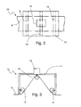
- the structure of the above-mentioned sliding block is schematically shown in figures 2 and 3.
- the sliding block also includes a pipe union 15, linked to the vacuum chamber 8 of the mobile table 5, that allows the sliding block to intercept the vacuum generated by the vacuum chamber and transmit it to the mobile table, which is fitted with suitable holes on its upper surface, in such a way as to keep the printed substrate, e.g. a paper sheet, on which the processing stations are operating, in touch with such a surface.
- the proposed invention gets rid of the troubles caused by the tensions that arise between the belt and the dragging chain due to their different lengths, that may even cause the belt to rip off or, less pessimistically, to either crumple or tighten up, resulting in a lower-quality vacuum or even in a vacuum loss.
- the belt wears down less than in the conventional approaches.
Landscapes
- Engineering & Computer Science (AREA)
- Mechanical Engineering (AREA)
- Screen Printers (AREA)
Applications Claiming Priority (2)
| Application Number | Priority Date | Filing Date | Title |
|---|---|---|---|
| ITMI20040963 ITMI20040963A1 (it) | 2004-05-13 | 2004-05-13 | Macchina da stampa serigrafica a piu' stazioni di lavoro |
| ITMI20040963 | 2004-05-13 |
Publications (1)
| Publication Number | Publication Date |
|---|---|
| EP1595698A2 true EP1595698A2 (fr) | 2005-11-16 |
Family
ID=34939784
Family Applications (1)
| Application Number | Title | Priority Date | Filing Date |
|---|---|---|---|
| EP20050103919 Withdrawn EP1595698A2 (fr) | 2004-05-13 | 2005-05-11 | Machine pour impression sérigraphique avec plusieurs stations |
Country Status (2)
| Country | Link |
|---|---|
| EP (1) | EP1595698A2 (fr) |
| IT (1) | ITMI20040963A1 (fr) |
Cited By (4)
| Publication number | Priority date | Publication date | Assignee | Title |
|---|---|---|---|---|
| WO2009030899A1 (fr) * | 2007-09-03 | 2009-03-12 | Dek International Gmbh | Système et procédé de traitement de pièces |
| CN103203978A (zh) * | 2013-04-03 | 2013-07-17 | 邱耀光 | 多色印刷机的真空吸附系统 |
| CN104494296A (zh) * | 2014-12-31 | 2015-04-08 | 东莞市塘厦鸿镁丝印移印机械厂 | 一种气动步进式穿梭移动工作台 |
| DE102024122632A1 (de) | 2023-08-10 | 2025-02-13 | Ulrich Loser | Vorrichtung und Verfahren zur Förderung von zu bedruckenden Gegenständen in einer Druckmaschine und Druckmaschine |
Families Citing this family (1)
| Publication number | Priority date | Publication date | Assignee | Title |
|---|---|---|---|---|
| CN115489195A (zh) * | 2022-09-08 | 2022-12-20 | 东莞佳华自动化科技有限公司 | 一种多色印刷生产线以及印刷方法 |
-
2004
- 2004-05-13 IT ITMI20040963 patent/ITMI20040963A1/it unknown
-
2005
- 2005-05-11 EP EP20050103919 patent/EP1595698A2/fr not_active Withdrawn
Cited By (7)
| Publication number | Priority date | Publication date | Assignee | Title |
|---|---|---|---|---|
| WO2009030899A1 (fr) * | 2007-09-03 | 2009-03-12 | Dek International Gmbh | Système et procédé de traitement de pièces |
| US10682848B2 (en) | 2007-09-03 | 2020-06-16 | Asm Assembly Systems Singapore Pte. Ltd. | Workpiece processing system and method |
| CN103203978A (zh) * | 2013-04-03 | 2013-07-17 | 邱耀光 | 多色印刷机的真空吸附系统 |
| CN103203978B (zh) * | 2013-04-03 | 2014-11-19 | 深圳市科精诚印刷机械制造有限公司 | 多色印刷机的真空吸附系统 |
| CN104494296A (zh) * | 2014-12-31 | 2015-04-08 | 东莞市塘厦鸿镁丝印移印机械厂 | 一种气动步进式穿梭移动工作台 |
| CN104494296B (zh) * | 2014-12-31 | 2017-02-22 | 东莞市塘厦鸿镁丝印移印机械厂 | 一种气动步进式穿梭移动工作台 |
| DE102024122632A1 (de) | 2023-08-10 | 2025-02-13 | Ulrich Loser | Vorrichtung und Verfahren zur Förderung von zu bedruckenden Gegenständen in einer Druckmaschine und Druckmaschine |
Also Published As
| Publication number | Publication date |
|---|---|
| ITMI20040963A1 (it) | 2004-08-13 |
Similar Documents
| Publication | Publication Date | Title |
|---|---|---|
| FI92802B (fi) | Menetelmä ja laite nesteen poistamiseksi nesteen ja kiinteän aineen sekoituksesta | |
| ITBO950521A1 (it) | Apparecchiatura e metodo per la formazione di gruppi ordinati di prodotti da alimentare a passo. | |
| CZ20014000A3 (cs) | Systém pro přenáąení plechovek s otočnou deskou | |
| JP6393326B2 (ja) | 生地片延展方法、生地片延展装置及び生地片延展装置を備えた巻き上げ生地整形装置 | |
| GB1055785A (en) | Apparatus for separating a top permeable workpiece from a stack thereof | |
| EP1595698A2 (fr) | Machine pour impression sérigraphique avec plusieurs stations | |
| US8732995B2 (en) | Method and apparatus for feeding a laundry article to a mangle or the like | |
| JP5329122B2 (ja) | 布類展張搬送方法及び布類展張搬送機 | |
| JP2000296961A (ja) | 枚葉紙処理機械用吸引ベルトコンベヤ | |
| GB2047650A (en) | Roll wrapping apparatus | |
| JPH1081421A (ja) | シート状生産物のスタック把持器及びスタック把持器を使用するパレット処理方法 | |
| JPH07284599A (ja) | 衣服を折り畳む方法及び装置 | |
| US5845759A (en) | Cloth piece transfer apparatus with side inverter | |
| ITBO960098A1 (it) | Gruppo convogliatore di prodotti | |
| JP4136112B2 (ja) | 枚葉印刷機のシート状物案内装置 | |
| CN102137805B (zh) | 隔断装置及片材集聚系统 | |
| GB1589778A (en) | Wrapping apparatus and a method of wrapping | |
| JP3949993B2 (ja) | 印刷機のパウダー装置 | |
| US5632202A (en) | Device for placing a cylindrical screen in, and removing it from, a rotary screen printing machine | |
| GB2278345A (en) | Suction type grippers for a sheet-transfer drum | |
| JP6034105B2 (ja) | ラベル貼付装置 | |
| CA2451331C (fr) | Methode et dispositif d'emballage d'objets plats | |
| US20080264003A1 (en) | Device for Supplying and/or Filling Bags | |
| JPH05116746A (ja) | 軽量ボトルの横列群供給方法及びその装置 | |
| US3451670A (en) | Sheet slowdown mechanism |
Legal Events
| Date | Code | Title | Description |
|---|---|---|---|
| PUAI | Public reference made under article 153(3) epc to a published international application that has entered the european phase |
Free format text: ORIGINAL CODE: 0009012 |
|
| AK | Designated contracting states |
Kind code of ref document: A2 Designated state(s): AT BE BG CH CY CZ DE DK EE ES FI FR GB GR HU IE IS IT LI LT LU MC NL PL PT RO SE SI SK TR |
|
| AX | Request for extension of the european patent |
Extension state: AL BA HR LV MK YU |
|
| STAA | Information on the status of an ep patent application or granted ep patent |
Free format text: STATUS: THE APPLICATION IS DEEMED TO BE WITHDRAWN |
|
| 18D | Application deemed to be withdrawn |
Effective date: 20071201 |