EP1595320B1 - Lichtbogenfehlerdetektion für auf sspc basierende elektrische energieverteilungssysteme - Google Patents
Lichtbogenfehlerdetektion für auf sspc basierende elektrische energieverteilungssysteme Download PDFInfo
- Publication number
- EP1595320B1 EP1595320B1 EP04709913A EP04709913A EP1595320B1 EP 1595320 B1 EP1595320 B1 EP 1595320B1 EP 04709913 A EP04709913 A EP 04709913A EP 04709913 A EP04709913 A EP 04709913A EP 1595320 B1 EP1595320 B1 EP 1595320B1
- Authority
- EP
- European Patent Office
- Prior art keywords
- load
- solid state
- current
- switching device
- signature
- Prior art date
- Legal status (The legal status is an assumption and is not a legal conclusion. Google has not performed a legal analysis and makes no representation as to the accuracy of the status listed.)
- Expired - Lifetime
Links
- 238000001514 detection method Methods 0.000 title claims description 9
- 239000007787 solid Substances 0.000 claims description 43
- 238000000034 method Methods 0.000 claims description 18
- 230000001052 transient effect Effects 0.000 claims description 10
- 238000005259 measurement Methods 0.000 claims description 8
- 230000002159 abnormal effect Effects 0.000 claims description 3
- 238000010586 diagram Methods 0.000 description 8
- 230000006870 function Effects 0.000 description 6
- 238000012360 testing method Methods 0.000 description 4
- 239000004020 conductor Substances 0.000 description 3
- 238000012545 processing Methods 0.000 description 3
- 238000005516 engineering process Methods 0.000 description 2
- 238000005452 bending Methods 0.000 description 1
- 238000009429 electrical wiring Methods 0.000 description 1
- 230000003628 erosive effect Effects 0.000 description 1
- 238000009413 insulation Methods 0.000 description 1
- 230000010354 integration Effects 0.000 description 1
- 238000012544 monitoring process Methods 0.000 description 1
- 239000000126 substance Substances 0.000 description 1
- 208000024891 symptom Diseases 0.000 description 1
Images


Classifications
-
- H—ELECTRICITY
- H02—GENERATION; CONVERSION OR DISTRIBUTION OF ELECTRIC POWER
- H02H—EMERGENCY PROTECTIVE CIRCUIT ARRANGEMENTS
- H02H1/00—Details of emergency protective circuit arrangements
- H02H1/0007—Details of emergency protective circuit arrangements concerning the detecting means
- H02H1/0015—Using arc detectors
-
- H—ELECTRICITY
- H02—GENERATION; CONVERSION OR DISTRIBUTION OF ELECTRIC POWER
- H02H—EMERGENCY PROTECTIVE CIRCUIT ARRANGEMENTS
- H02H3/00—Emergency protective circuit arrangements for automatic disconnection directly responsive to an undesired change from normal electric working condition with or without subsequent reconnection ; integrated protection
- H02H3/08—Emergency protective circuit arrangements for automatic disconnection directly responsive to an undesired change from normal electric working condition with or without subsequent reconnection ; integrated protection responsive to excess current
-
- H—ELECTRICITY
- H02—GENERATION; CONVERSION OR DISTRIBUTION OF ELECTRIC POWER
- H02H—EMERGENCY PROTECTIVE CIRCUIT ARRANGEMENTS
- H02H3/00—Emergency protective circuit arrangements for automatic disconnection directly responsive to an undesired change from normal electric working condition with or without subsequent reconnection ; integrated protection
- H02H3/006—Calibration or setting of parameters
-
- H—ELECTRICITY
- H02—GENERATION; CONVERSION OR DISTRIBUTION OF ELECTRIC POWER
- H02H—EMERGENCY PROTECTIVE CIRCUIT ARRANGEMENTS
- H02H3/00—Emergency protective circuit arrangements for automatic disconnection directly responsive to an undesired change from normal electric working condition with or without subsequent reconnection ; integrated protection
- H02H3/08—Emergency protective circuit arrangements for automatic disconnection directly responsive to an undesired change from normal electric working condition with or without subsequent reconnection ; integrated protection responsive to excess current
- H02H3/10—Emergency protective circuit arrangements for automatic disconnection directly responsive to an undesired change from normal electric working condition with or without subsequent reconnection ; integrated protection responsive to excess current additionally responsive to some other abnormal electrical conditions
Definitions
- the present invention relates to electrical power distribution, and more particularly to arc fault detection/protection in a solid state power controller (SSPC) based power distribution system.
- SSPC solid state power controller
- An electrical arc fault is defined as electrical current through a gas in a broken or disconnected circuit.
- the disconnected circuit can be between two deteriorated conductors, between one deteriorated conductor and ground plane (parallel arc) or between adjacent ends of a conductor (series arc).
- Arc fault conditions may be attributed to a variety of causes, such as damage to wiring, insulation, or contacts due to age, heat, chemical erosion, bending stress, etc.
- GB 2348751 discloses a system for detecting arc faults in an aircraft power system, and includes, as micro processor for detecting arc conditions by comparing sensed current to various thresholds that distinguish normally occurring load currents from arcing currents.
- the present invention is directed to an apparatus and a method for arc fault protection in an electrical power distribution system of a vehicle.
- the present invention is particularly applicable to protect against faults occurring downstream of an SSPC, which selectively provides electrical power to an associated load.
- An SSPC distribution system has the advantage of having in its internal control circuitry the information about the load connected at its output - load signature ( load current at steady state, start up, shut down, switching events, etc.).
- This data can be either pre-stored in memory or determined when installed in the vehicle by a process of "learning.” Such learning may be achieved through successive testing and storage of results in memory. Such testing may be performed to determine the steady state load current waveform, start up and shut down, characteristic signatures.
- an apparatus for arc fault protection in an electrical power distribution system of a vehicle said power distribution system including a plurality of solid state power switching devices for switching on/off power to corresponding loads and further including a solid state power switching device controller for distributing switching control signals to said solid state power switching device, said apparatus comprising:
- a method for protecting against arc faults in an electrical power distribution system of a vehicle said power distribution system including a plurality of solid state power switching devices for switching on/off power to corresponding loads and further including a solid state power switching device controller for distributing switching control signals to said solid state power switching devices, said method comprising:
- FIG. 2 is a block diagram illustrating details of SSPC based power switching, short circuit/over current and arc fault protection device in accordance with an embodiment of the present application;
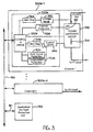
- FIG. 3 is a block diagram illustrating an alternative configuration for SSPC based power switching and arc fault protection in accordance with an embodiment of the present invention
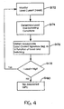
- FIG. 4 is a flow diagram illustrating an arc fault protection technique in accordance with principles of the present invention.
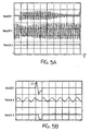
- FIG. 5A illustrates an exemplary load current under a normal (no arc fault) load current condition
- Figure 5B illustrates an arc fault condition in the same circuit which is identified by the detection circuit as an arc fault, in accordance with principles of the present invention.
- FIG. 1 illustrates, in block diagram form, elements of an exemplary SSPC based power distribution system to which principles of the present invention may be applied to achieve arc fault protection.
- the exemplary power distribution system illustrated in FIG. 1 includes: a power bus 100; a plurality of SSPC units 300-1 to 300-n; a plurality of loads 140-1 to 140-n, respectively connected to SSPC units 300-1 to 300-n; and an SSPC controller 120.
- the power bus 100 may provide either AC or DC power for distribution to components (i.e., loads) of an aircraft or some other vehicle.
- Each SSPC unit 300-1 to 300-n is a solid state switching device connected to the power bus 100 to selectively provide rated electrical power to one of loads 140-1 to 140-n (e.g., pumps, lights, etc.) based on instructions received from the SSPC controller 120.
- the power distribution system illustrated in FIG. 1 may be implemented as part of an ELMC (Electrical Load Management Center) of a vehicle and may be implemented in various levels of integration, for example using a modular architecture such as described in co-pending Application Serial No. 10/017,125, filed December 14, 2001.
- the SSPC controller 120 is a functional element, which generates switching control signals to be distributed to the plurality of SSPC units 300-1 to 300-n based on control information received via a gateway module from a centralized vehicle computer (not shown).
- the SSPC controller 120 may gather testing, monitoring, and reporting information from the plurality of SSPC units 300-1 to 300-n, for example to monitor and report failed switching devices and various other fault conditions of the electrical distribution system, including short circuit, overcurrent and arc fault conditions described in more detail below.
- FIG. 2 illustrates an exemplary configuration of an SSPC unit 300a in accordance with an exemplary embodiment of the present invention.
- the SSPC unit 300a of this exemplary embodiment includes two main components: a power switching device 310; and a switching control and protection device 320a.
- the power switching device 310 which may be, for example, a MOSFET transistor is coupled to the power bus 100 to selectively provide power to an associated load under control of the switching control and protection device 320a.
- the power switching device 310 shown in FIG. 2 includes a temperature sensor 312 for providing thermal condition information to the switching control and protection device 320a and a sense resistor 314 for providing a load current measurement to the switching control and protection device 320a.
- the switching control and protection device 320a includes a control/driver unit 322a for selectively opening/closing the power switching device 310 in accordance with switching commands received from the SSPC controller unit 120 via a data bus 150 and in accordance with locally determined conditions. More specifically, the switching control and protection device 320a includes a current sensor 340 for measuring output current of the power switching device 310 based on the current at the sense resistor 314 of the power switching device 310, the measured current being provided to a zero current crossing detector 346 (when the electrical power supplied at the power bus 100 is AC electrical power), a short circuit protection unit 324, an overcurrent protection unit 326, and an arc fault protection unit 330.
- the short circuit and overcurrent protection units 324, 326 may perform well known short circuit/overcurrent detection, for example based on an I 2 t trip curve.
- the arc fault protection unit 330 performs arc fault detection in a manner described in more detail below.
- the controller/driver 322a is connected to each of the short circuit protection unit 324, the overcurrent protection unit 326, and the arc fault protection unit 330 to disable (i.e., trip), the power switching device 310 when a short circuit condition, an overcurrent condition, or an arc fault condition occurs, and reports fault conditions to the SSPC controller 120 via the data bus 150.
- the switching control and protection device 320a further includes a thermal protection circuit 328 for sensing excessive heat of the power switching device 310, as indicated by the temperature sensor 312 of the power switching device 310.
- the controller/driver 322a is connected to the output of the thermal protection circuit 328 so as to selectively disable the powerswitching device 310 upon occurrence of an excessive thermal condition.
- the switching control and protection device 320a further includes a voltage sensor 342, connected to an input of the power switching device 310, and a zero voltage crossing detector 340 for detecting zero voltage crossings based on the output of the voltage sensor 342.
- the controller/driver 322a controls opening/closing of the power switching device 310 in accordance with zero voltage crossing detected by the zero voltage crossing detector 342 and zero current crossing indicated by the zero current crossing detector 346.
- FIG. 2 illustrates functional components of the switching control and protection device 320a as discrete elements, it should be realized that various functional elements illustrated in FIG. 2 may be combined in a single processing element, such as a microcomputer with associated memory, or may be distributed among a plurality of processing elements.
- the switching control and protection device 320a may be implemented as one or more application specific integrated circuits (ASICs), or may be implemented in various combinations of hardware and software.
- ASICs application specific integrated circuits
- the SSPC unit 300a may be grouped with SSPCs for a plurality of loads on a single card of a load management module.
- additional elements may be included with the physical implementation of the SSPC unit 300a illustrated in FIG. 2, and/or certain elements may be removed.
- FIG. 3 illustrates an alternative embodiment for power switching and arc fault protection in accordance with principles of the present invention.
- an SSPC unit 300b comprises the power switching device 310; and a switching control and protection device 320b.
- the switching control and protection device 320b shown in FIG. 3 does not include an arc fault protection unit (i.e., there is no one-to-one correspondence between SSPC unit and arc fault detector).
- a dedicated arc fault protection unit 160 connected to the data bus 150 via an input 161, monitors the total load current supplied to a plurality of load channels 1 to n.
- the dedicated arc fault protection unit 160 measures the total load current passed to the plurality of channels (300b-1 to 300b-n) and also receives load current information from each of the attached channels.
- the arc fault protection unit 160 receives current information from a current sensor (e.g., current transformer, not shown) located on the feed line that feeds the power bus 100 shown in FIG. 1. This allows the arc fault protection unit 160 to acquire information on the total current fed to the plurality of loads.
- the arc fault protection unit 160 is able to process the total current information with an elevated degree of accuracy and resolution. Upon detection of an anomaly in the total transferred current, the arc fault protection unit 160 detects which one of the channels 300b-1 to 300b-n has reported an abnormal current.
- the arc fault protection unit 160 will trip the circuit, which exhibited the arc fault symptoms.
- the dedicated arc fault protection unit 160 may be implemented as an ASIC, a microcontroller or as a combination of hardware/software.
- the dedicated arc fault protection unit 160 may be a functional element of the SSPC controller 120 or some other element of the electrical power distribution system.
- FIG. 4 is a flow diagram illustrating arc fault protection in accordance with principles of the present application.
- the functions of the flow diagram illustrated in FIG. 4 may be, for example, implemented in the dedicated arc fault protection unit 160 of the embodiment illustrated in FIG. 3 or in each individual SSPC unit 300-1 to 300-n, as shown in FIG. 2.
- dedicated arc fault protection unit 160 may be a functional unit of the SSPC controller 120 or some other element of the electrical power distribution system.
- an undesired arc fault condition is detected based on a comparison of load currents and acceptable load signatures.
- FIGS. 5A-5B depict two cases of load current.
- FIG. 5A shows a normal inrush current during the start up of a three phase motor.
- the output of the arc detection circuit shown in Trace 3 does not react to the sudden inrush of current (shown in Trace 1), due to the fact that the load signature is recognized by the arc fault protection unit.
- Trace 2 of FIG. 5A illustrates the bus voltage for the normal load current condition of FIG. 5A.
- FIG. 5B shows the case of an actual arc fault current.
- the load current waveform (Trace 1) is not recognized by the unit and, therefore, a trip signal is generated (Trace 3) disconnecting the SSPC.
- Trace 2 of FIG. 5B illustrates the bus voltage for the arc fault condition of FIG. 5A.
- a load signature is typically unique, with some variations caused by the operating conditions, fixed or variable frequency power, characteristics of the load itself, etc. These variations can be defined in an allowable band of a load signature, stored in the logic/processing circuitry of the distribution system. Furthermore, this information can be derived from an existing "library" of loads available from the load manufacturer. Furthermore, load signatures may be taught during a learning process, in which the arc fault protection circuitry determines characteristics of the various loads and operating conditions (e.g., inrush, steady state and transients). This may take place automatically when loads are switched on/off or during various other steady state and transient operation events.
- characteristics of the various loads and operating conditions e.g., inrush, steady state and transients
- the current output to each of the plurality of loads, I load is monitored (S172). Furthermore, switching conditions for each load (i.e., whether an associate power switching device 310 is turned on and for what length the power switching device has been turned on) and characteristics of the load are determined (S174). Steps S172 and S174 may be reversed in order or performed concurrently.
- an acceptable load current signature, I sig is determined as a function of load and switching conditions, for example by retrieving a load signature from a "library" of loads (S176) and I load is compared to I sig to determine whether the measured load current is within acceptable limits. If I load is not within acceptable limits of I sig , the associated power switching device is disabled due to an arc fault condition (S180). Acceptable limits may be determined through testing.
- detecting arc fault conditions based on load signature takes advantage of switching information obtained from the SSPC controller unit 120 and characteristics of the associated load so that nuisance trips can be avoided. More specifically, the load signature used to determine arc faults will take into account the switching state of the power switching device, thereby avoiding switching trips due to transient or noise conditions of the power distribution channel.
Landscapes
- Emergency Protection Circuit Devices (AREA)
Claims (10)
- Vorrichtung (320, 160) für Störlichtbogenschutz in einem Elektrizitätsverteilungssystem eines Fahrzeugs, wobei das Leistungsverteilungssystem mehrere Festkörperleistungsschalteinrichtungen (310) zum Ein-/Ausschalten von Leistung zu entsprechenden Lasten (140) enthält und weiterhin einen Festkörperleistungsschalteinrichtungscontroller (120) zum Verteilen von Schaltsteuersignalen an die Festkörperleistungsschalteinrichtung (310) enthält, wobei die Vorrichtung umfaßt:einen Laststromeingang (320, 161), der ausgelegt ist, eine Messung eines einer Last (140) über eine Festkörperleistungsschalteinrichtung (310) des Elektrizitätsverteilungssystems zugeführten Stroms zu erhalten;einen Lastsignatureingang, der ausgelegt ist, von der der Last (140) zugeführten Stromwellenformen Dauer- und Einschwingreferenzcharakteristiken zu erhalten, um dadurch eine Lastsignatur zu erhalten, wobei die Lastsignatur eine Funktion von Charakteristiken der Last (140), der Strom über die Festkörperleistungsschalteinrichtung (310) zugeführt wird, und Arbeitsbedingungen der Festkörperleistungsschalteinrichtung ist; und gekennzeichnet durcheinen Störlichtbogendetektor (330, 160), der ausgelegt ist, einen Schaltzustand der Festkörperleistungsschalteinrichtung (310) zu bestimmen und den gemessenen Laststrom mit einer Lastsignatur als Funktion des bestimmten Schaltzustandes der Festkörperleistungsschalteinrichtung zu vergleichen, wobei der Störlichtbogendetektor ein Störlichtbogenanzeigesignal ausgibt, wenn der gemessene Strom außerhalb eines zulässigen Bereichs der Lastsignatur liegt.
- Vorrichtung (320, 160) nach Anspruch 1, wobei die Lastsignatur eine Funktion eines Schaltzustands der Festkörperleistungsschalteinrichtung (310) ist, so daß die Lastsignatur Einschwingzustände des Elektrizitätsverteilungssystems verfolgt.
- Vorrichtung (320, 160) nach Anspruch 1, wobei die Lastsignatur eine Funktion des der Last über die Festkörperleistungsschalteinrichtung (310) zugeführten Leistungstyps ist.
- Vorrichtung (320, 160) nach Anspruch 1, wobei
der Laststromeingang (161) ausgelegt ist, eine Messung eines mehreren Lasten (140) über entsprechende Festkörperleistungsschalteinrichtungen (310) zugeführten Stroms zu erhalten und
der Störlichtbogendetektor (160) einen insgesamt gemessenen Laststrom mit einer Lastsignatur vergleicht und bei der Detektion einer Anomalie bestimmt, welche der angeschlossenen Festkörperleistungsschalteinrichtungen (310) einen anomalen Strom meldet, um den relevanten betroffenen Stromkreis abzuschalten. - Vorrichtung (320, 160) nach Anspruch 1, wobei der Störlichtbogendetektor (330, 160) ausgelegt ist, Einschwing- und Dauercharakteristiken der Last während eines Initialisierungsprozesses zu bestimmen, um die Lastsignatur zu bestimmen.
- Verfahren zum Schützen vor Störlichtbögen in einem Elektrizitätsverteilungssystem eines Fahrzeugs, wobei das Leistungsverteilungssystem mehrere Festkörperleistungsschalteinrichtungen (310) zum Ein-/Ausschalten von Leistung zu entsprechenden Lasten (140) enthält und weiterhin einen Festkörperleistungsschalteinrichtungscontroller (120) zum Verteilen von Schaltsteuersignalen an die Festkörperleistungsschalteinrichtungen (310) enthält, wobei das Verfahren folgendes umfaßt:Erhalten (S172) einer Messung eines einer Last über eine Festkörperleistungsschalteinrichtung des Elektrizitätsverteilungssystems zugeführten Stroms;Erhalten (S176) von Dauer- und Einschwingreferenzcharakteristiken der der Last (140) zugeführten Stromwellenformen, um dadurch eine Lastsignatur zu bestimmen, wobei die Lastsignatur eine Funktion von Charakteristiken der Last (140), der Strom über die Festkörperleistungsschalteinrichtung (310) zugeführt wird, und Arbeitsbedingungen der Festkörperleistungsschalteinrichtung ist; und gekennzeichnet durchBestimmen eines Schaltzustands der Festkörperleistungsschalteinrichtung (310);Vergleichen (S178) des gemessenen Laststroms mit der Lastsignatur als einer Funktion des bestimmten Schaltzustandes der Festkörperleistungsschalteinrichtung (310); undAusgeben (S180) eines Störlichtbogenanzeigesignals, wenn der gemessene Strom außerhalb eines zulässigen Bereichs der Lastsignatur liegt.
- Verfahren nach Anspruch 6, wobei die Lastsignatur eine Funktion eines Schaltzustands der Festkörperleistungsschalteinrichtung (310) ist, so daß die Lastsignatur Einschwingzustände des Elektrizitätsverteilungssystems verfolgt.
- Verfahren nach Anspruch 9, wobei die Lastsignatur eine Funktion des der Last über die Festkörperleistungsschalteinrichtung (310) zugeführten Leistungstyps ist.
- Verfahren nach Anspruch 6, wobei
der Schritt (S172) des Erhaltens einer Laststrommessung einer Messung eines mehreren Lasten (140) über entsprechende Festkörperleistungsschalteinrichtungen (310) zugeführten Stroms erhält; und
der Vergleichsschritt (S178) einen insgesamt gemessenen Laststrom mit einer Lastsignatur vergleicht, wobei, wenn der Vergleichsschritt eine Anomalie detektiert, das Verfahren bestimmt, welche der angeschlossenen Festkörperleistungsschalteinrichtungen (310) einen anomalen Strom meldet, Störlichtbogenort zu bestimmen. - Verfahren nach Anspruch 6, wobei der Schritt (S176) des Erhaltens einer Lastsignatur Einschwing- und Dauercharakteristiken der Last während eines Initialisierungsprozesses bestimmt, um die Lastsignatur zu bestimmen.
Applications Claiming Priority (3)
| Application Number | Priority Date | Filing Date | Title |
|---|---|---|---|
| US10/365,371 US7177125B2 (en) | 2003-02-12 | 2003-02-12 | Arc fault detection for SSPC based electrical power distribution systems |
| US365371 | 2003-02-12 | ||
| PCT/US2004/003927 WO2004073131A1 (en) | 2003-02-12 | 2004-02-10 | Arc fault detection for sspc based electrical power distribution systems |
Publications (2)
| Publication Number | Publication Date |
|---|---|
| EP1595320A1 EP1595320A1 (de) | 2005-11-16 |
| EP1595320B1 true EP1595320B1 (de) | 2007-11-21 |
Family
ID=32824632
Family Applications (1)
| Application Number | Title | Priority Date | Filing Date |
|---|---|---|---|
| EP04709913A Expired - Lifetime EP1595320B1 (de) | 2003-02-12 | 2004-02-10 | Lichtbogenfehlerdetektion für auf sspc basierende elektrische energieverteilungssysteme |
Country Status (5)
| Country | Link |
|---|---|
| US (1) | US7177125B2 (de) |
| EP (1) | EP1595320B1 (de) |
| JP (1) | JP2006517781A (de) |
| DE (1) | DE602004010236T2 (de) |
| WO (1) | WO2004073131A1 (de) |
Cited By (1)
| Publication number | Priority date | Publication date | Assignee | Title |
|---|---|---|---|---|
| CN104865462A (zh) * | 2015-04-10 | 2015-08-26 | 南京南瑞继保电气有限公司 | 一种故障处理方法及装置 |
Families Citing this family (78)
| Publication number | Priority date | Publication date | Assignee | Title |
|---|---|---|---|---|
| US6943558B2 (en) * | 2003-09-15 | 2005-09-13 | The Boeing Company | System and method for remotely detecting electric arc events in a power system |
| DE102004037924A1 (de) * | 2004-08-04 | 2006-03-16 | Endress + Hauser Process Solutions Ag | Modulartige Anschlußvorrichtung in einem Bussystem zum Schutz eines elektrischen Verbrauchers |
| WO2007106062A2 (en) * | 2005-02-16 | 2007-09-20 | Leach International Corporation | Power distribution system using solid state power controllers |
| DE102005014725B3 (de) * | 2005-03-31 | 2006-08-17 | Infineon Technologies Ag | Schutzanordnung für Leistungshalbleiterbauelement gegen Überstrom und Übertemperatur |
| JP4713963B2 (ja) * | 2005-07-07 | 2011-06-29 | 矢崎総業株式会社 | 過電流検出装置 |
| DE102005046925A1 (de) * | 2005-09-30 | 2007-04-19 | Siemens Ag | Schaltgerät zum Schalten mindestens eines Stromes |
| US7796366B2 (en) * | 2005-12-09 | 2010-09-14 | Hamilton Sundstrand Corporation | AC arc fault detection and protection |
| US8659856B2 (en) * | 2005-12-09 | 2014-02-25 | Hamilton Sundstrand Corporation | DC arc fault detection and protection |
| US7505820B2 (en) * | 2006-03-30 | 2009-03-17 | Honeywell International Inc. | Backup control for solid state power controller (SSPC) |
| GB0606904D0 (en) * | 2006-04-06 | 2006-05-17 | Rolls Royce Plc | Electrical Fault Detection |
| US20070279068A1 (en) * | 2006-05-31 | 2007-12-06 | Harres Daniel N | Power diagnostic system and method |
| US7656628B2 (en) * | 2006-08-04 | 2010-02-02 | International Business Machines Corporation | Apparatus for providing fault protection in a circuit supplying power to an electronic device |
| US20080043393A1 (en) * | 2006-08-18 | 2008-02-21 | Honeywell International Inc. | Power switching device |
| US7656634B2 (en) * | 2006-11-30 | 2010-02-02 | Hamilton Sundstrand Corporation | Increasing the system stability and lightning capability in a power distribution system that utilizes solid-state power controllers |
| US7489138B2 (en) | 2006-11-30 | 2009-02-10 | Honeywell International Inc. | Differential arc fault detection |
| KR100870618B1 (ko) * | 2006-12-29 | 2008-11-25 | 엘에스산전 주식회사 | 기중차단기의 보호장치 |
| US7706116B2 (en) * | 2007-01-22 | 2010-04-27 | Honeywell International Inc. | SSPC technology incorporated with thermal memory effects to achieve the fuse curve coordination |
| US7634329B2 (en) * | 2007-03-05 | 2009-12-15 | Honeywell International Inc. | Intelligent aircraft secondary power distribution system that facilitates condition based maintenance |
| US8050806B2 (en) * | 2007-03-21 | 2011-11-01 | Honeywell International Inc. | Ground fault interruption using DSP based SSPC module |
| US7834637B2 (en) * | 2007-09-21 | 2010-11-16 | Honeywell International Inc. | Method and apparatus for generalized AC and DC arc fault detection and protection |
| DE102008004869A1 (de) * | 2008-01-17 | 2009-07-30 | Siemens Aktiengesellschaft | Lichtbogenschutzmodul |
| US8148848B2 (en) * | 2008-01-24 | 2012-04-03 | Honeywell International, Inc. | Solid state power controller (SSPC) used as bus tie breaker in electrical power distribution systems |
| US7626798B2 (en) | 2008-01-24 | 2009-12-01 | Honeywell International Inc. | Electronic load control unit (ELCU) used as bus tie breaker in electrical power distribution systems |
| US8520352B2 (en) * | 2008-02-25 | 2013-08-27 | Xylem Ip Holdings Llc | Multiple-channel active sensing and switching device |
| US7973533B2 (en) | 2008-02-27 | 2011-07-05 | Vertical Power, Inc. | In-circuit testing for integrity of solid-state switches |
| US7868621B2 (en) * | 2008-03-04 | 2011-01-11 | Honeywell International Inc. | Power line communication based aircraft power distribution system with real time wiring integrity monitoring capability |
| DE102008018256B4 (de) * | 2008-03-31 | 2023-04-27 | Siemens Aktiengesellschaft | Steuermodul mit Anschlusseinrichtungen zum Anschluss an Anschlussklemmen eines Verbraucherabzweiges sowie Verbraucherabzweig |
| KR101576541B1 (ko) * | 2008-07-14 | 2015-12-21 | 삼성전자 주식회사 | 전원장치 및 그 안전제어방법 |
| US20100142104A1 (en) * | 2008-12-08 | 2010-06-10 | Cooper Anthony A | System and method for electrical protection of appliances |
| US8981265B2 (en) | 2008-12-30 | 2015-03-17 | Ppg Industries Ohio, Inc. | Electric circuit and sensor for detecting arcing and a transparency having the circuit and sensor |
| EP2457313B1 (de) | 2009-07-23 | 2014-03-05 | Enphase Energy, Inc. | Verfahren und vorrichtung zur erkennung und kontrolle von dc-störlichtbögen |
| US20110109502A1 (en) * | 2009-11-09 | 2011-05-12 | Sullivan Steven J | Apparatus, system and method for displaying construction-related documents |
| US8322658B2 (en) * | 2010-04-05 | 2012-12-04 | The Boeing Company | Automated fire and smoke detection, isolation, and recovery |
| US8320090B2 (en) | 2010-06-08 | 2012-11-27 | Hamilton Sundstrand Corporation | SSPC for parallel arc fault detection in DC power system |
| US20120275071A1 (en) * | 2011-04-28 | 2012-11-01 | Texas Instruments Incorporated | Arc-fault detection |
| US20120306612A1 (en) * | 2011-06-05 | 2012-12-06 | Triune Ip Llc | Electric Line Interface System |
| US9551751B2 (en) | 2011-06-15 | 2017-01-24 | Ul Llc | High speed controllable load |
| US8890463B2 (en) | 2011-08-25 | 2014-11-18 | Hamilton Sundstrand Corporation | Direct current bus management controller |
| US8829826B2 (en) | 2011-08-25 | 2014-09-09 | Hamilton Sundstrand Corporation | Regenerative load electric power management systems and methods |
| US8952570B2 (en) | 2011-08-25 | 2015-02-10 | Hamilton Sundstrand Corporation | Active damping with a switched capacitor |
| US8553373B2 (en) | 2011-08-25 | 2013-10-08 | Hamilton Sundstrand Corporation | Solid state power controller for high voltage direct current systems |
| US8669743B2 (en) | 2011-08-25 | 2014-03-11 | Hamilton Sundstrand Corporation | Direct current electric power system with active damping |
| US8625243B2 (en) * | 2011-08-25 | 2014-01-07 | Hamilton Sundstrand Corporation | Multi-functional solid state power controller |
| GB2509009B (en) | 2011-08-30 | 2016-03-09 | Ge Aviat Systems Ltd | Power distribution in aircraft |
| US20130154351A1 (en) * | 2011-12-19 | 2013-06-20 | Mark J. Seger | Electrical architecture with power optimization |
| US9229036B2 (en) | 2012-01-03 | 2016-01-05 | Sentient Energy, Inc. | Energy harvest split core design elements for ease of installation, high performance, and long term reliability |
| US9182429B2 (en) | 2012-01-04 | 2015-11-10 | Sentient Energy, Inc. | Distribution line clamp force using DC bias on coil |
| US9413156B2 (en) | 2012-07-27 | 2016-08-09 | San Diego Gas & Electric Company | System for detecting a falling electric power conductor and related methods |
| CN103812082A (zh) * | 2012-11-08 | 2014-05-21 | 李品德 | 一种新型电弧光保护系统 |
| JP6081967B2 (ja) * | 2014-07-28 | 2017-02-15 | ファナック株式会社 | 出力コモンのオンオフ機能付き出力モジュール |
| US9923371B1 (en) * | 2014-08-13 | 2018-03-20 | Rosendin Electric, Inc. | Shared resource system |
| US9768605B2 (en) * | 2014-12-29 | 2017-09-19 | Eaton Corporation | Arc fault detection system and method and circuit interrupter employing same |
| US9954354B2 (en) | 2015-01-06 | 2018-04-24 | Sentient Energy, Inc. | Methods and apparatus for mitigation of damage of power line assets from traveling electrical arcs |
| BR112017018108A2 (pt) * | 2015-02-25 | 2018-04-10 | General Electric Technology Gmbh | ?circuito de saída digital? |
| CN105094116B (zh) * | 2015-07-01 | 2017-10-10 | 西北工业大学 | 交流固态功率控制器快速电弧故障检测数据预处理方法 |
| US9984818B2 (en) | 2015-12-04 | 2018-05-29 | Sentient Energy, Inc. | Current harvesting transformer with protection from high currents |
| EP3176903B1 (de) * | 2015-12-04 | 2023-09-20 | HS Elektronik Systeme GmbH | Stromversorgungssystem |
| GB2546553B (en) | 2016-01-25 | 2020-08-26 | Ge Aviat Systems Ltd | Circuit and method for detecting arc faults |
| US10634733B2 (en) | 2016-11-18 | 2020-04-28 | Sentient Energy, Inc. | Overhead power line sensor |
| JP6807552B2 (ja) | 2017-02-14 | 2021-01-06 | パナソニックIpマネジメント株式会社 | アーク検出回路、開閉器システム、パワーコンディショナシステム及びアーク検出方法 |
| GB2563592B (en) | 2017-06-19 | 2019-11-06 | Ge Aviat Systems Ltd | Arc mitigation in electrical power distribution system |
| CA3094177A1 (en) | 2018-03-20 | 2019-09-26 | Whisker Labs, Inc. | Detection of electric discharges that precede fires in electrical wiring |
| WO2020021656A1 (ja) * | 2018-07-25 | 2020-01-30 | 三菱電機株式会社 | 半導体遮断器及び遮断装置 |
| US11476674B2 (en) | 2018-09-18 | 2022-10-18 | Sentient Technology Holdings, LLC | Systems and methods to maximize power from multiple power line energy harvesting devices |
| US11041915B2 (en) | 2018-09-18 | 2021-06-22 | Sentient Technology Holdings, LLC | Disturbance detecting current sensor |
| US12050241B2 (en) | 2018-10-15 | 2024-07-30 | Sentient Technology Holdings, Llc. | Power line sensors with automatic phase identification |
| US11125832B2 (en) | 2018-12-13 | 2021-09-21 | Sentient Technology Holdings, LLC | Multi-phase simulation environment |
| US11615925B2 (en) * | 2018-12-26 | 2023-03-28 | Eaton Intelligent Power Limited | Hazardous location compliant circuit protection devices having enhanced safety intelligence, systems and methods |
| WO2020163367A1 (en) | 2019-02-04 | 2020-08-13 | Sentient Energy, Inc. | Power supply for electric utility underground equipment |
| US10998935B2 (en) | 2019-02-20 | 2021-05-04 | Honeywell Limited | Secondary electric power distribution system (SEPDS) to facilitate aircraft connectivity |
| US12241925B2 (en) | 2019-12-27 | 2025-03-04 | Eaton Intelligent Power Limited | Arc fault detection modules for vehicle electrical systems |
| US11597337B2 (en) * | 2020-02-04 | 2023-03-07 | Tusimple, Inc. | Power management system for autonomous vehicles |
| CN115985706A (zh) * | 2021-10-15 | 2023-04-18 | 施耐德电器工业公司 | 用于固态断路器的过载保护方法,固态断路器和配电系统 |
| US12271172B2 (en) * | 2021-12-07 | 2025-04-08 | Hamilton Sundstrand Corporation | Solid state power controllers |
| DE102022203089A1 (de) | 2022-03-29 | 2023-10-05 | Ellenberger & Poensgen Gmbh | Verfahren zum Betrieb eines Überlastschutzes eines Fahrzeugs |
| FR3152887B1 (fr) * | 2023-09-07 | 2025-11-07 | Safran | Détection d’arcs électriques dans un circuit électrique d’un système aéronautique par constitution d’une base de motifs |
| WO2026058049A1 (en) * | 2024-09-10 | 2026-03-19 | Eaton Intelligent Power Limited | Fire risk detection method using electrical signatures for an electrical system in a building |
| FR3166438A1 (fr) | 2024-09-18 | 2026-03-20 | Safran | Détection d’arcs électriques dans un circuit électrique d’un système aéronautique par un modèle de mélange gaussien |
Family Cites Families (19)
| Publication number | Priority date | Publication date | Assignee | Title |
|---|---|---|---|---|
| US5455731A (en) * | 1992-06-08 | 1995-10-03 | United Technologies Corporation | Power controller reset during load starting |
| US5777894A (en) * | 1992-10-26 | 1998-07-07 | Ut Automotive Dearborn, Inc. | Monitoring and protecting drives controlled with microcontroller |
| US5550751A (en) | 1993-10-15 | 1996-08-27 | The Texas A & M University System | Expert system for detecting high impedance faults |
| US6034611A (en) | 1997-02-04 | 2000-03-07 | Square D Company | Electrical isolation device |
| US6259996B1 (en) | 1998-02-19 | 2001-07-10 | Square D Company | Arc fault detection system |
| US5752047A (en) * | 1995-08-11 | 1998-05-12 | Mcdonnell Douglas Corporation | Modular solid state power controller with microcontroller |
| US5835321A (en) | 1996-08-02 | 1998-11-10 | Eaton Corporation | Arc fault detection apparatus and circuit breaker incorporating same |
| US5834940A (en) | 1996-09-24 | 1998-11-10 | Brooks; Stanley J. | Arcing fault detector testing and demonstration system |
| US5835319A (en) | 1997-04-16 | 1998-11-10 | General Electric Company | Method and apparatus for circuit breaking |
| US6782329B2 (en) | 1998-02-19 | 2004-08-24 | Square D Company | Detection of arcing faults using bifurcated wiring system |
| US6625550B1 (en) | 1998-02-19 | 2003-09-23 | Square D Company | Arc fault detection for aircraft |
| US5986860A (en) | 1998-02-19 | 1999-11-16 | Square D Company | Zone arc fault detection |
| US6052046A (en) | 1998-07-24 | 2000-04-18 | Eaton Corporation | Miniaturized double pole circuit breaker with arc fault and ground fault protection |
| US6268989B1 (en) | 1998-12-11 | 2001-07-31 | General Electric Company | Residential load center with arcing fault protection |
| US6362628B2 (en) | 1998-12-21 | 2002-03-26 | Pass & Seymour, Inc. | Arc fault circuit detector device detecting pulse width modulation of arc noise |
| KR100423886B1 (ko) | 2000-05-12 | 2004-03-24 | 휴먼엘텍 주식회사 | 아크 결함 보호용 차단기 및 이를 구비하는 회로 차단기 |
| US6522509B1 (en) * | 2000-07-21 | 2003-02-18 | Eaton Corporation | Arc fault detection in ac electric power systems |
| WO2002017457A1 (en) | 2000-08-22 | 2002-02-28 | Human El-Tech, Inc. | Overload circuit interrupter capable of electrical tripping and circuit breaker with the same |
| US6525918B1 (en) * | 2001-09-11 | 2003-02-25 | Ford Global Technologies, Inc. | Adaptive arc fault detection and smart fusing system |
-
2003
- 2003-02-12 US US10/365,371 patent/US7177125B2/en not_active Expired - Fee Related
-
2004
- 2004-02-10 DE DE602004010236T patent/DE602004010236T2/de not_active Expired - Lifetime
- 2004-02-10 WO PCT/US2004/003927 patent/WO2004073131A1/en not_active Ceased
- 2004-02-10 JP JP2006503467A patent/JP2006517781A/ja not_active Withdrawn
- 2004-02-10 EP EP04709913A patent/EP1595320B1/de not_active Expired - Lifetime
Cited By (2)
| Publication number | Priority date | Publication date | Assignee | Title |
|---|---|---|---|---|
| CN104865462A (zh) * | 2015-04-10 | 2015-08-26 | 南京南瑞继保电气有限公司 | 一种故障处理方法及装置 |
| CN104865462B (zh) * | 2015-04-10 | 2018-11-13 | 南京南瑞继保电气有限公司 | 一种故障处理方法及装置 |
Also Published As
| Publication number | Publication date |
|---|---|
| JP2006517781A (ja) | 2006-07-27 |
| WO2004073131A1 (en) | 2004-08-26 |
| US7177125B2 (en) | 2007-02-13 |
| DE602004010236D1 (de) | 2008-01-03 |
| DE602004010236T2 (de) | 2008-09-25 |
| US20040156154A1 (en) | 2004-08-12 |
| EP1595320A1 (de) | 2005-11-16 |
Similar Documents
| Publication | Publication Date | Title |
|---|---|---|
| EP1595320B1 (de) | Lichtbogenfehlerdetektion für auf sspc basierende elektrische energieverteilungssysteme | |
| US7489138B2 (en) | Differential arc fault detection | |
| US7253637B2 (en) | Arc fault circuit interrupter system | |
| US7796366B2 (en) | AC arc fault detection and protection | |
| MX2007010546A (es) | Aparato y metodo para detectar la perdida de una conexion transformadora de corriente que acopla un rele diferencial limitacorriente a un elemento de un sistema de energia. | |
| CN115461637B (zh) | 用于检测熔断器失效的方法和装置 | |
| US6426856B1 (en) | Method for monitoring a protective gear | |
| EP0995252A1 (de) | Selbstgespeistes isoliertes verriegelungssystem zur bereichsauswahl für schutzschalter mit elektronischer auslöseschaltung | |
| US8659856B2 (en) | DC arc fault detection and protection | |
| US8427794B2 (en) | Multi-pole arc-fault circuit interrupter | |
| EP0604037B1 (de) | Verfahren zum Schutz einer Sammelschiene | |
| JP3796428B2 (ja) | 配電線地絡電流増幅装置 | |
| CN112578274A (zh) | 断路器和移动设备 | |
| KR101019462B1 (ko) | 임펄스 검출을 이용한 아크결함 판단방법 | |
| EP1816720A2 (de) | Elektrisches Schaltgerät, Stromverteilungssystem und Verfahren unter Anwendung eines Stoppauslösers | |
| EP3317741B1 (de) | Sicherheitsschaltung, sicherheitsschaltungsbetriebsverfahren und ein elektrisch betriebener motor mit einer sicherheitsschaltung | |
| EP1069665A2 (de) | Energieübertragungsleitung und Steuerverfahren | |
| JP4272171B2 (ja) | 電力系統運用方法 | |
| KR100664897B1 (ko) | 디지털 보호 계전기 및 그 제어방법 | |
| JP3210810B2 (ja) | 保護継電装置及びそのアナログ部故障判定方法 | |
| JP2003134662A (ja) | 調相設備の保護装置 | |
| JP2004015972A (ja) | 電流変化幅継電器を使用した保護継電装置 | |
| JPH1141782A (ja) | 電力系統の総合異常判定装置及び保護装置 | |
| KR20040092098A (ko) | 전기설비를 갖는 전력계통의 지락 보호장치 | |
| JPH11262169A (ja) | 系統保護装置 |
Legal Events
| Date | Code | Title | Description |
|---|---|---|---|
| PUAI | Public reference made under article 153(3) epc to a published international application that has entered the european phase |
Free format text: ORIGINAL CODE: 0009012 |
|
| 17P | Request for examination filed |
Effective date: 20050912 |
|
| AK | Designated contracting states |
Kind code of ref document: A1 Designated state(s): AT BE BG CH CY CZ DE DK EE ES FI FR GB GR HU IE IT LI LU MC NL PT RO SE SI SK TR |
|
| AX | Request for extension of the european patent |
Extension state: AL LT LV MK |
|
| DAX | Request for extension of the european patent (deleted) | ||
| RBV | Designated contracting states (corrected) |
Designated state(s): DE ES FR GB IT |
|
| GRAP | Despatch of communication of intention to grant a patent |
Free format text: ORIGINAL CODE: EPIDOSNIGR1 |
|
| GRAJ | Information related to disapproval of communication of intention to grant by the applicant or resumption of examination proceedings by the epo deleted |
Free format text: ORIGINAL CODE: EPIDOSDIGR1 |
|
| GRAP | Despatch of communication of intention to grant a patent |
Free format text: ORIGINAL CODE: EPIDOSNIGR1 |
|
| GRAS | Grant fee paid |
Free format text: ORIGINAL CODE: EPIDOSNIGR3 |
|
| GRAA | (expected) grant |
Free format text: ORIGINAL CODE: 0009210 |
|
| AK | Designated contracting states |
Kind code of ref document: B1 Designated state(s): DE ES FR GB IT |
|
| REG | Reference to a national code |
Ref country code: GB Ref legal event code: FG4D |
|
| REF | Corresponds to: |
Ref document number: 602004010236 Country of ref document: DE Date of ref document: 20080103 Kind code of ref document: P |
|
| PG25 | Lapsed in a contracting state [announced via postgrant information from national office to epo] |
Ref country code: ES Free format text: LAPSE BECAUSE OF FAILURE TO SUBMIT A TRANSLATION OF THE DESCRIPTION OR TO PAY THE FEE WITHIN THE PRESCRIBED TIME-LIMIT Effective date: 20080304 |
|
| ET | Fr: translation filed | ||
| PLBE | No opposition filed within time limit |
Free format text: ORIGINAL CODE: 0009261 |
|
| STAA | Information on the status of an ep patent application or granted ep patent |
Free format text: STATUS: NO OPPOSITION FILED WITHIN TIME LIMIT |
|
| 26N | No opposition filed |
Effective date: 20080822 |
|
| PGFP | Annual fee paid to national office [announced via postgrant information from national office to epo] |
Ref country code: GB Payment date: 20090106 Year of fee payment: 6 |
|
| PGFP | Annual fee paid to national office [announced via postgrant information from national office to epo] |
Ref country code: FR Payment date: 20090206 Year of fee payment: 6 |
|
| GBPC | Gb: european patent ceased through non-payment of renewal fee |
Effective date: 20100210 |
|
| REG | Reference to a national code |
Ref country code: FR Ref legal event code: ST Effective date: 20101029 |
|
| PG25 | Lapsed in a contracting state [announced via postgrant information from national office to epo] |
Ref country code: FR Free format text: LAPSE BECAUSE OF NON-PAYMENT OF DUE FEES Effective date: 20100301 |
|
| PG25 | Lapsed in a contracting state [announced via postgrant information from national office to epo] |
Ref country code: IT Free format text: LAPSE BECAUSE OF NON-PAYMENT OF DUE FEES Effective date: 20080229 |
|
| PG25 | Lapsed in a contracting state [announced via postgrant information from national office to epo] |
Ref country code: GB Free format text: LAPSE BECAUSE OF NON-PAYMENT OF DUE FEES Effective date: 20100210 |
|
| PGFP | Annual fee paid to national office [announced via postgrant information from national office to epo] |
Ref country code: DE Payment date: 20150227 Year of fee payment: 12 |
|
| REG | Reference to a national code |
Ref country code: DE Ref legal event code: R119 Ref document number: 602004010236 Country of ref document: DE |
|
| PG25 | Lapsed in a contracting state [announced via postgrant information from national office to epo] |
Ref country code: DE Free format text: LAPSE BECAUSE OF NON-PAYMENT OF DUE FEES Effective date: 20160901 |
|
| P01 | Opt-out of the competence of the unified patent court (upc) registered |
Effective date: 20230525 |